nz course tunnelling - amazon web services general remarks any tunnelling activity causes ground...
TRANSCRIPT

An NZGS 1 day short course
Ground movement control
Tunnelling
Antonio GensTechnical University of Catalonia, Barcelona, Spain

Introduction Ground movements generated by tunnelling Procedures for ground movement control
General Tunnelling procedure (TBMs) Screen (curtain) walls Structural movement compensation Compensation grouting
Final remarks
Outline
Introduction
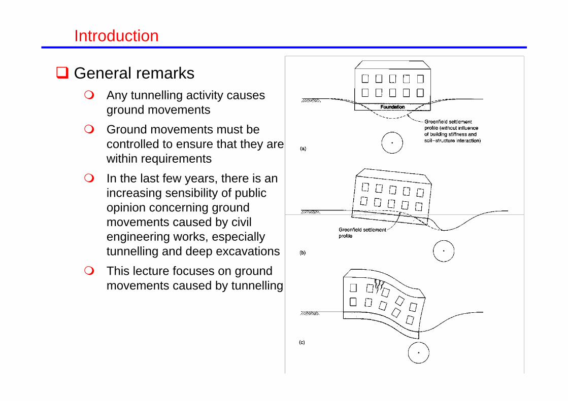
General remarks Any tunnelling activity causes
ground movements Ground movements must be
controlled to ensure that they are within requirements
In the last few years, there is an increasing sensibility of public opinion concerning ground movements caused by civil engineering works, especially tunnelling and deep excavations
This lecture focuses on ground movements caused by tunnelling

Introduction
Ground and foundation movement Rotation or slope, Angular strain (distortion), Relative deflection, Deflection ratio, /L Tilt, Relative rotation Average horizontal strainh=l/L

Introduction Damage criteria
Boscardin & Cording (1989)

Introduction Damage criteria
Burland et al. (1977)

Damage criteria
Burland (1998)
Introduction

Damage criteria
Boscardin & Cording (1989) Burland (1998)
Introduction

Tunnelling methods
Open-face tunnelling
NATM or SCL
Tunnelling methods
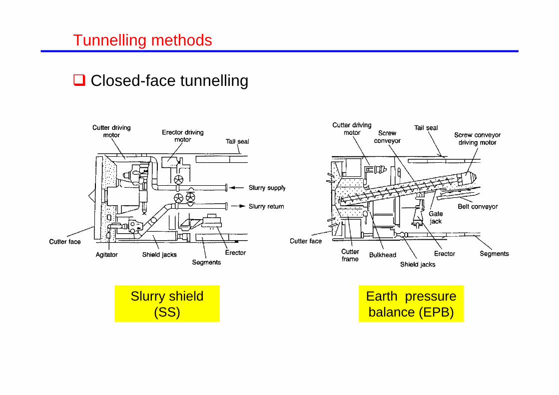
Closed-face tunnelling
Slurry shield (SS)
Earth pressure balance (EPB)

Tunnelling methods
Selection of closed-face tunnelling method
Tunnelling methods
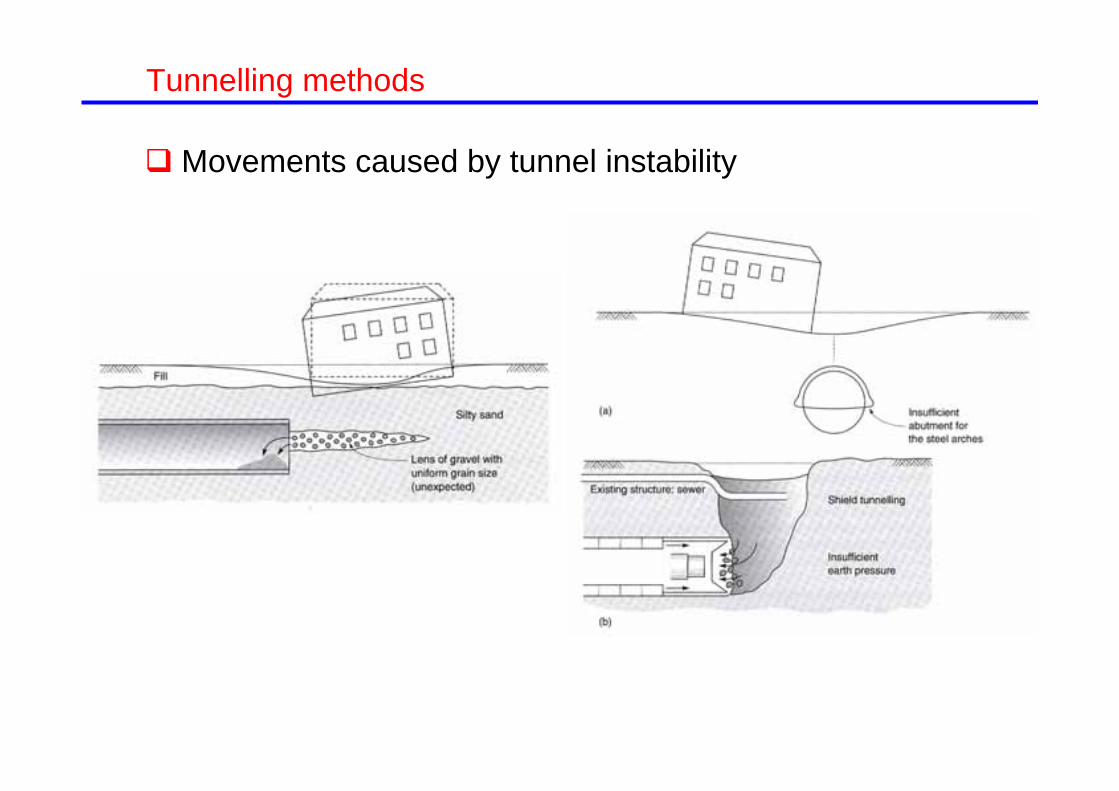
Movements caused by tunnel instability

Introduction Ground movements generated by tunnelling Procedures for ground movement control
General Tunnelling procedure (TBMs) Screen (curtain) walls Structural movement compensation Compensation grouting
Final remarks
Outline

Ground movements caused by tunnelling Settlement trough
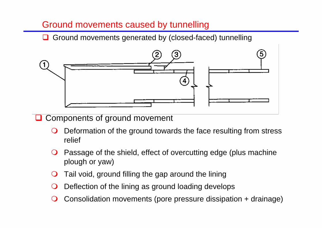
Ground movements caused by tunnelling Ground movements generated by (closed-faced) tunnelling
Components of ground movement Deformation of the ground towards the face resulting from stress
relief Passage of the shield, effect of overcutting edge (plus machine
plough or yaw) Tail void, ground filling the gap around the lining Deflection of the lining as ground loading develops Consolidation movements (pore pressure dissipation + drainage)

Ground movements caused by tunnelling Ground movements generated by (open-faced) tunnelling
Components of ground movement Deformation of the ground towards the face resulting from stress
relief Passage of the shield, effect of overcutting edge (plus machine
plough or yaw) Tail void, ground filling the gap around the lining Deflection of the lining as ground loading develops Consolidation movements (pore pressure dissipation + drainage)

D
/4DπV VL loss Volume 2
s
yi
s
Inflection pointSettlement
maxs s i 2πV Volume
2
2
max 2iyexpss
smax
Ground movements caused by tunnelling Settlement trough: volume loss
2
max 32Ds VLi

Ground movements caused by tunnelling Settlement trough width
D
yi
s
Inflexion pointSettlement
smax
D
yi
s
Inflexion pointSettlement
smaxz0
Peck (1969)

Ground movements caused by tunnelling Settlement trough width: clays
D
yi
s
Inflexion pointSettlement
smax
D
yi
s
Inflexion pointSettlement
smaxz0
Mair & Taylor (1997)
oi Kz
K = = 0.5 in claysO’Reilly & New (1982)

Ground movements caused by tunnelling Settlement trough width
D
yi
s
Inflexion pointSettlement
smax
D
yi
s
Inflexion pointSettlement
smaxz0
oi Kz
K = 0.25 in sandsMair & Taylor (1987)
O’Reilly & New (1982)

Ground movements caused by tunnelling Subsurface movements
Mair et al. (1993)Clays
Sands
0.175 0.325(1 / )1 /
o
o
z zKz z

Ground movements caused by tunnelling Horizontal movements
Attewell (1978) O’Reilly & New (1982)
0h v
ys sz
2
2max
1.65 exp2
h
h
s y ys i i

Ground movements caused by tunnelling Horizontal movements

Ground movements caused by tunnelling Horizontal movements
Hong & Bae (1995)
NATM in sands

Ground movements caused by tunnelling Development of ground movements
Attewell & Woodman (1982) suggested using the cumulative probability curve 21( ) exp( / 2)
2( ) 1 ( )
G d
G G

Ground movements caused by tunnelling Development of ground movements
Moh et al. (1996)
EPB tunnelling in silty sands in Taipei EPB tunnelling in sands in Cairo
Ata (1996)

Ground movements caused by tunnelling Typical ground losses:
Open faced tunnelling: 1% - 2% in stiff clay (London clay). NATM in London clay: 0.5%-1.5%
Closed-face tunnelling around 0.5%. In soft clays 1% - 2% Beware of mixed face situations or when granular/fill lies on top of the
tunnel
Madrid Metro observations
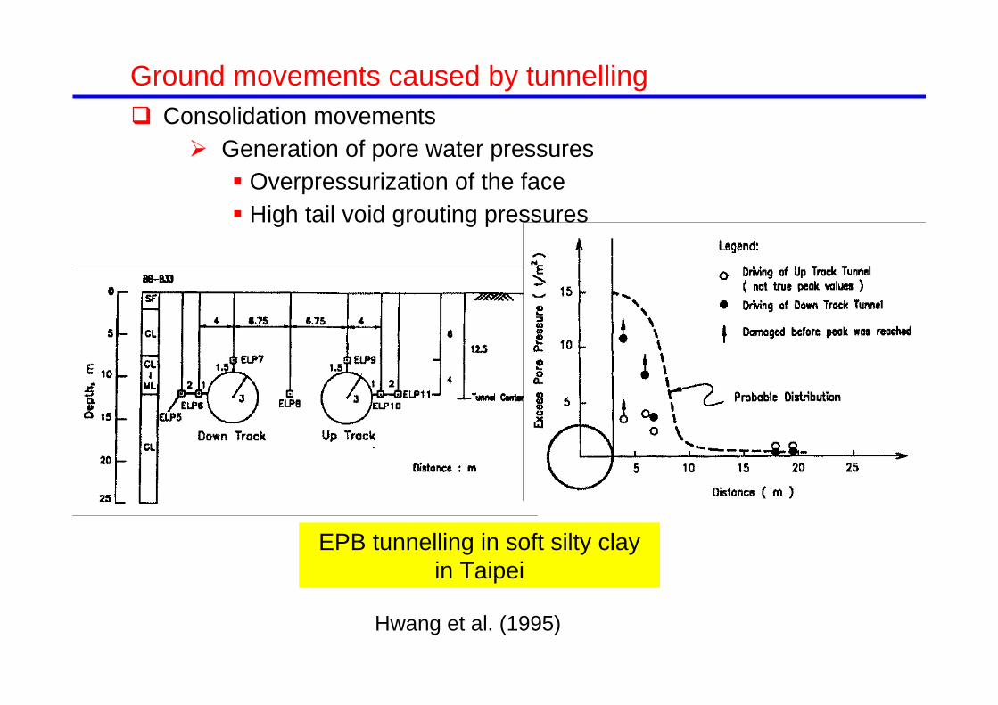
Ground movements caused by tunnelling Consolidation movements
Generation of pore water pressures Overpressurization of the face High tail void grouting pressures
Hwang et al. (1995)
EPB tunnelling in soft silty clay in Taipei

Ground movements caused by tunnelling Consolidation movements: two sources
Dissipation of pore water pressures generated: trough width similar to the short-term one
Tunnel lining acting as a drain: wide settlement trough
Shirlaw (1995)
Long term settlement troughs for tunnels in soft clays
Immediate and post construction settlements in London clay
Bowers et al. (1996)

Ground movements caused by tunnelling Effect of the stiffness of the building
Treasury building and St. James greenfield site
Viggiani and Standing (2001)
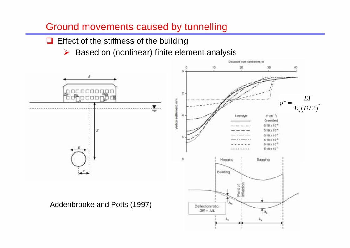
Ground movements caused by tunnelling Effect of the stiffness of the building
Based on (nonlinear) finite element analysis
Addenbrooke and Potts (1997)
2*( / 2)s
EIE B

Ground movements caused by tunnelling Effect of the stiffness of the building
Based on (nonlinear) finite element analysis
Modification factors for deflection ratio
Addenbrooke and Potts (1997)
Modification factors for horizontal strain
2*( / 2)s
EIE B
*( / 2)s
EAE B

Ground movements caused by tunnelling
Modification factors for deflection ratio
(Franzius et al., 2006)
Modification factors for horizontal strain
*mod 2
0s
EIE z B L
Effect of the stiffness of the building Based on more finite element analysis including 3-D analyses, building
weight, building width, interfaces.
*mod
s
EAE BL

Ground movements caused by tunnelling Assessing the risk of building damage: The Jubilee line procedure
(Burland et al., 2002) Three stages of assessment:
Preliminary assessment: a simple and conservative approach, check settlement less than 10 mm and less the 1/500
Second stage assessment: make use of “greenfield”empirical predictions and damage criteria. The stiffness of the building may be taken into account but is it not often done
Detailed evaluation for those buildings classifies as being at risk of category 3 damage or greater. If confirmed, design remedial measures (MGT)
Jubilee line, accepted category damage: 2 There is a tendency to reduce the category of accepted damage
In Barcelona Metro and High speed train tunnelling, accepted damage category is 0!

Introduction Ground movements generated by tunnelling Procedures for ground movement control
General Tunnelling procedure (TBMs) Screen (curtain) walls Structural movement compensation Compensation grouting
Final remarks
Outline
Structural measures Deep and shallow
underpinning Increase tensile capacity Reducing sensitivity of the
structure Structure jacking Barrel vaulting
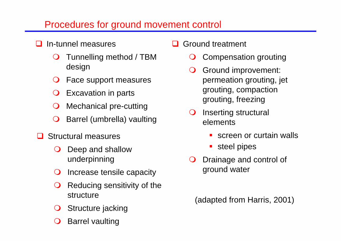
Procedures for ground movement control
In-tunnel measures Tunnelling method / TBM
design Face support measures Excavation in parts Mechanical pre-cutting Barrel (umbrella) vaulting
(adapted from Harris, 2001)
Ground treatment Compensation grouting Ground improvement:
permeation grouting, jet grouting, compaction grouting, freezing
Inserting structural elements screen or curtain walls steel pipes
Drainage and control of ground water

In-tunnel measures
Procedures for ground movement control
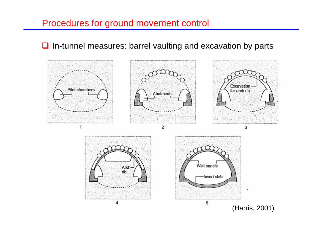
In-tunnel measures: barrel vaulting and excavation by parts
Procedures for ground movement control
(Harris, 2001)

Structural measures Deep and shallow
underpinning Increase tensile capacity Reducing sensitivity of the
structure Structure jacking Barrel vaulting
Procedures for ground movement control
In-tunnel measures Tunnelling method / TBM
design Face support measures Excavation in parts Mechanical pre-cutting Barrel (umbrella) vaulting
(adapted from Harris, 2001)
Ground treatment Compensation grouting Ground improvement:
permeation grouting, jet grouting, compaction grouting, freezing
Inserting structural elements screen or curtain walls steel pipes
Drainage and control of ground water

Introduction Ground movements generated by tunnelling Procedures for ground movement control
General Tunnelling procedure (TBMs) Screen (curtain) walls Structural movement compensation Compensation grouting
Final remarks
Outline

Closed shield machine. Earth pressure balance TBM (EPB)
Tunnelling procedure TBM

West Portal
Stratford BoxMade Ground & Terrace Gravel
Groundwater table in upper aquifer
Groundwater table in lower aquifer
London Clay
Woolwich & Reading Beds
Upnor FormationThanet Sand
Chalk
Chainage (m)
Elev
atio
n(m
)
40
3020
10
0-10-20
-30
-40
King’s Cross
Tunnelling procedure Geology of Channel Tunnel Rail Link (C220)
7.4 km of twin tunnels of 8.1 m diameter

Tunnelling procedure Face pressure control Channel Tunnel Rail Link (C220)
London clayLambeth group
(Borghi & Mair, 2006)

WRB+UF
TS+UF
Thanet Sand (TS)TS+Chalk
Woolwich and Reading Beds(WRB)
WRB+HFWRB+HF+LC
London Clay (LC)0
0.20.40.60.81.01.21.4
1000 3000 5000 7000 9000Chainage (m)
Volu
me
loss
(%)
Stratford BoxWest Portal
Control de movimientos causados por túneles Volume loss CTRL C220 (Wongsaroj et al., 2005)
Acknowledgments to R.J. Mair

Barcelona Metro: Line 9
27.2 km: 12.3 m diameter tunnel 11.9 km: 9.4 m diameter tunnel 5.0 km: cut and cover tunnel
0.9 km: mined tunnel 2.8 km: viaduct
TOTAL: 47.8 km (52 stations)

Barcelona Metro: Line 9
Mixed mode TBM 11,95m dia.
EPB 12,06m Ø dia. (2)
EPB 9,40m dia. (2)
TBMs used

Barcelona Metro: Line 9
Soil profile in the Llobregat delta

Barcelona Metro: Line 9
EPB Mas Blau- MercabarnaDiameter 9.4 m

0,0
0,5
1,0
1,5
2,0
2,5
3,0
3,5
‐1000 ‐500 0 500 1000 1500
Distance (m)
Gro
und
loss
(%)
Barcelona Metro: Line 9
EPB Mas Blau- Aeroport EPB Mas Blau- Mercabarna
Volume loss
IVIII
II
I

Barcelona Metro: Line 9
Volume loss
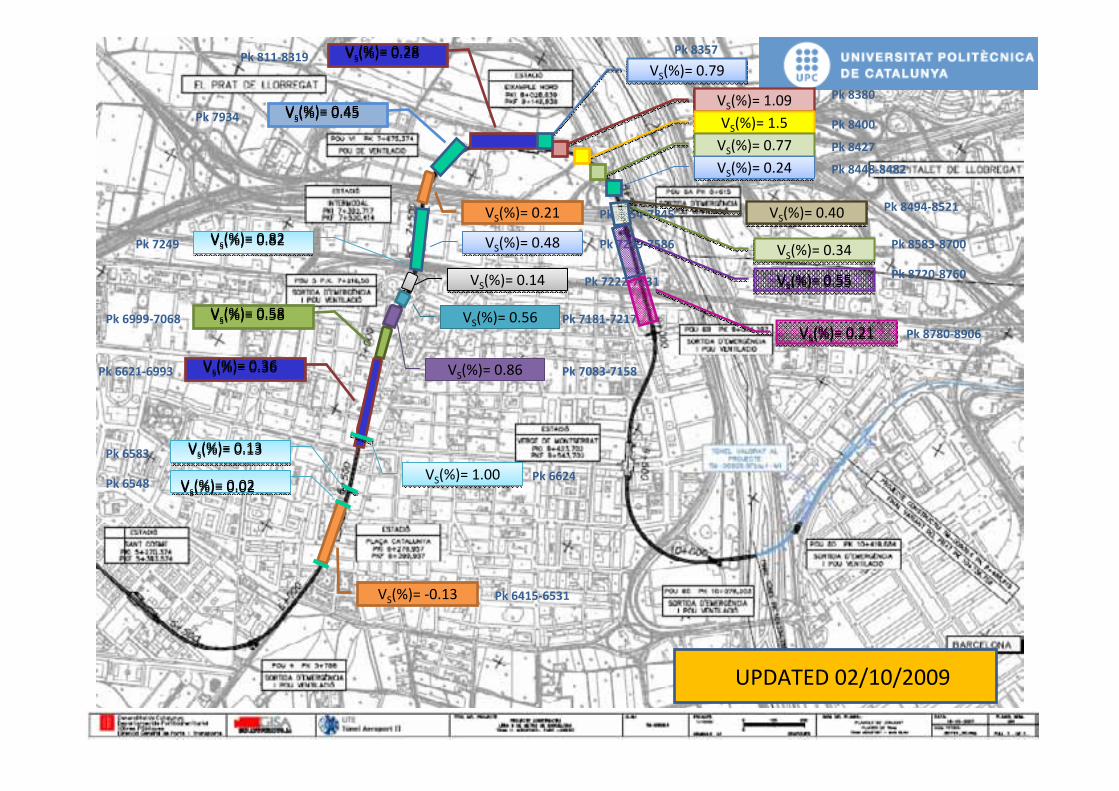
VS(%)= ‐0.13 Pk 6415‐6531
Vs(%)= 0.02Vs(%)= 0.02
Vs(%)= 0.13Vs(%)= 0.13
Vs(%)= 0.36Vs(%)= 0.36
Pk 6548
Pk 6583
Pk 6621‐6993
VS(%)= 1.00VS(%)= 1.00 Pk 6624
Vs(%)= 0.58Vs(%)= 0.58Pk 6999‐7068
VS(%)= 0.86 Pk 7083‐7158
VS(%)= 0.56 Pk 7181‐7217
VS(%)= 0.14VS(%)= 0.14 Pk 7222‐7231
Pk 7249 Vs(%)= 0.82Vs(%)= 0.82 VS(%)= 0.48VS(%)= 0.48 Pk 7249‐7586
VS(%)= 0.21 Pk 7654‐7845
Vs(%)= 0.45Vs(%)= 0.45Pk 7934
Vs(%)= 0.28Vs(%)= 0.28Pk 811‐8319 Pk 8357
VS(%)= 1.09VS(%)= 1.09Pk 8380
VS(%)= 1.5VS(%)= 1.5 Pk 8400
VS(%)= 0.77VS(%)= 0.77 Pk 8427
VS(%)= 0.24VS(%)= 0.24 Pk 8448‐8482
VS(%)= 0.79VS(%)= 0.79
VS(%)= 0.40VS(%)= 0.40Pk 8494‐8521
VS(%)= 0.34VS(%)= 0.34Pk 8583‐8700
UPDATED 02/10/2009
VS(%)= 0.55VS(%)= 0.55Pk 8720‐8760
VS(%)= 0.21VS(%)= 0.21 Pk 8780‐8906

P1 = Face pressureP2 = Shield pressureP3 = Grouting pressure
Face pressure
Shield bentonite pressure
Grouting pressure in the annulus between
soil and lining
EPB tunnelling Tunnelling pressures
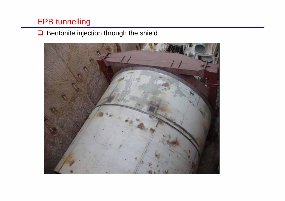
53EPB tunnelling Bentonite injection through the shield

SHAFTSHAFT
EPB tunnelling Recorded grouting pressure, P3

EPB tunnelling Volume loss before passage of EPB (ahead of face)
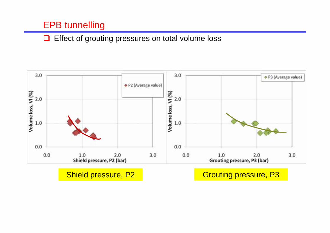
EPB tunnelling Effect of grouting pressures on total volume loss
Shield pressure, P2 Grouting pressure, P3

Introduction Ground movements generated by tunnelling Procedures for ground movement control
General Tunnelling procedure (TBMs) Screen (curtain) walls Structural movement compensation Compensation grouting
Final remarks
Outline

Quaternary Sandy silt
with gravel
Miocene Stiff clay matrix
with boulders
Fill
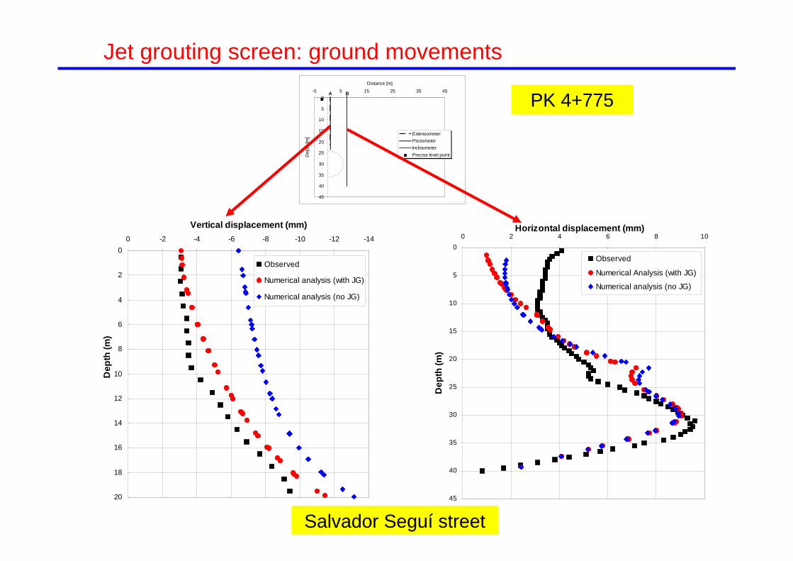
Salvador Seguí street
Screen (curtain) walls Jet-grouting screen

Jet grouting screen: ground movements
-10-8-6-4-202468
1012
-40 -20 0 20 40
Distance from tunnel axis [m]
Verti
cal d
ispl
acem
ent [
mm
]
Jet GroutingPassage of EPBFinal
PK 4+800
-10-8-6-4-202468
1012
-40 -20 0 20 40
Distance from tunnel axis [m]
Verti
cal d
ispl
acem
ent [
mm
] Jet GroutingPassage of EPBFinal PK 4+770
Salvador Seguí street

0
5
10
15
20
25
30
35
40
45
0 2 4 6 8 10Horizontal displacement (mm)
Dep
th (m
)
Observed
Numerical Analysis (with JG)
0
2
4
6
8
10
12
14
16
18
20
-14-12-10-8-6-4-20
Vertical displacement (mm)
Dep
th (m
)
Observed
Numerical analysis (with JG)
PK 4+7750
5
10
15
20
25
30
35
40
45
-5 5 15 25 35 45Distance [m]
Dep
th [m
] ExtensometerPiezometerInclinometerPrecise level point
A B
Jet grouting screen: ground movements
Salvador Seguí street
0
5
10
15
20
25
30
35
40
45
0 2 4 6 8 10Horizontal displacement (mm)
Dep
th (m
)
Observed
Numerical Analysis (with JG)
Numerical analysis (no JG)
0
2
4
6
8
10
12
14
16
18
20
-14-12-10-8-6-4-20
Vertical displacement (mm)
Dep
th (m
)
Observed
Numerical analysis (with JG)
Numerical analysis (no JG)
PK 4+7750
5
10
15
20
25
30
35
40
45
-5 5 15 25 35 45Distance [m]
Dep
th [m
] ExtensometerPiezometerInclinometerPrecise level point
A B
Jet grouting screen: ground movements
Salvador Seguí street

-7
-6
-5
-4
-3
-2
-1
0-50 -40 -30 -20 -10 0 10 20 30 40 50
Distance from tunnel axis [m]
Verti
cal d
ispl
acem
ent [
mm
]
Observed
Numerical analysis (with JG)
SettlementsPérdida de volumen, Vl,reducida de 0.35% a 0.27%
Jet grouting screen: ground movementsJet grouting screen: ground movements
Salvador Seguí street

-7
-6
-5
-4
-3
-2
-1
0-50 -40 -30 -20 -10 0 10 20 30 40 50
Distance from tunnel axis [m]
Verti
cal d
ispl
acem
ent [
mm
]
Observed
Numerical analysis (with JG)
Numerical analysis (no JG)
SettlementsVolume loss reduced from 0.35% to 0.27%
Jet grouting screen: ground movements
Salvador Seguí street

Sant Adrià street
Screen (curtain) walls Pile screen wall
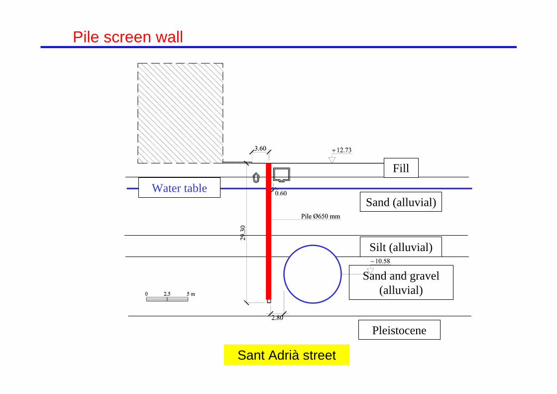
Sant Adrià street
Sand (alluvial)
Fill
Silt (alluvial)
Sand and gravel (alluvial)
Pleistocene
Water table
Pile screen wall

Sant Adrià street
Pile screen wall

Surface settlement on tunnel axis
-90
-80
-70
-60
-50
-40
-30
-20
-10
0
10
27/0
2/20
05
09/0
3/20
05
19/0
3/20
05
29/0
3/20
05
08/0
4/20
05
18/0
4/20
05
28/0
4/20
05
08/0
5/20
05
18/0
5/20
05
28/0
5/20
05
07/0
6/20
05
Date
Vert
ical
mov
emen
t [m
m]
T4B02973E000HN007WP
assa
ge o
f EP
B
Pile screen wall

Surface settlements
-90
-80
-70
-60
-50
-40
-30
-20
-10
0-60 -40 -20 0 20 40 60
Distance from tunnel axis [m]
Gro
und
vert
ical
dis
plac
emen
t [m
m]
Observed
Pile screen wall

-90
-80
-70
-60
-50
-40
-30
-20
-10
0-60 -40 -20 0 20 40 60
Distance from tunnel axis [m]
Gro
und
vert
ical
dis
plac
emen
t [m
m]
Observed
Hypothetical displacement profile with noBPW
Surface settlements
Pile screen wall

PK 2+973Sant Adrià street
0
5
10
15
20
25
30
35
-100 -90 -80 -70 -60 -50 -40 -30 -20 -10 0 10Vertical displacement [mm]
Dep
th [m
]
Observed
Numerical analysis (with BPW)
Numerical analysis (no BPW)
0
5
10
15
20
25
30
35
-100 -90 -80 -70 -60 -50 -40 -30 -20 -10 0 10Vertical displacement [mm]
Dep
th [m
]
Extensometer at tunnel axis
Numerical analysis (with BPW)
Numerical analysis (no BPW)
Vertical displacements
Pile screen wall

PK 2+973
0
5
10
15
20
25
30
35
40
45
-30 -20 -10 0 10 20 30 40 50Horizontal displacement [mm]
Dep
th [m
]
Inclinometer at 10m (L) from tunnel axis
Numerical analysis (with BPW)
Numerical analysis (no BPW)
0
5
10
15
20
25
30
35
40
45
-30 -20 -10 0 10 20 30 40 50Horizontal displacement [mm]
Dep
th [m
]
Observed
Numerical analysis (with BPW)
Numerical analysis (no BPW)
Sant Adrià street
Horizontal displacements
Pile screen wall

-90
-80
-70
-60
-50
-40
-30
-20
-10
0-60 -40 -20 0 20 40 60
Distance from tunnel axis [m]
Gro
und
vert
ical
dis
plac
emen
t [m
m]
Observed
Numerical analysis (with Bored Pile Wall)
Surface settlements
Pile screen wall

Surface settlements
-90
-80
-70
-60
-50
-40
-30
-20
-10
0-60 -40 -20 0 20 40 60
Distance from tunnel axis [m]
Gro
und
vert
ical
dis
plac
emen
t [m
m]
Observed
Numerical analysis (with bored pile wall)
Numerical analysis (no BPW)
Volume loss, Vlreduced from 1.90% to
1.68%
Pile screen wall

Burland-0.35
-0.30
-0.25
-0.20
-0.15
-0.10
-0.05
0.000.00 0.05 0.10 0.15 0.20 0.25 0.30 0.35
Horizontal tensile strain [%]
Def
lect
ion
ratio
[%]
Building (Case with BPW)
Building (Case with no BPW)
0
1
CATEGORY 2
CATEGORY 3 DAMAGE
CATEGORIES 4 AND 5 DAMAGE
PK 2+973Sant Adrià street
Pile screen wall
No pile screen wall
Pile screen wall

El Periódico
A tunnel close to the Sagrada Familia church (Barcelona) Building scheme

4.2 m
8.8m
12.0 m
11.1 m
31.5
m
17 m
A tunnel close to the Sagrada Familia church (Barcelona) Building scheme: cross section

Introduction Ground movements generated by tunnelling Procedures for ground movement control
General Tunnelling procedure (TBMs) Screen (curtain) walls Structural movement compensation Compensation grouting
Final remarks
Outline

Structure jacking Advantages
Very precise control of settlement is possible
The system is useful in areas with potentially steep settlement gradients
The jacks can be use to produce settlements or heave
Disadvantages Complexity Reaction time may be slow
specially for heavy structures
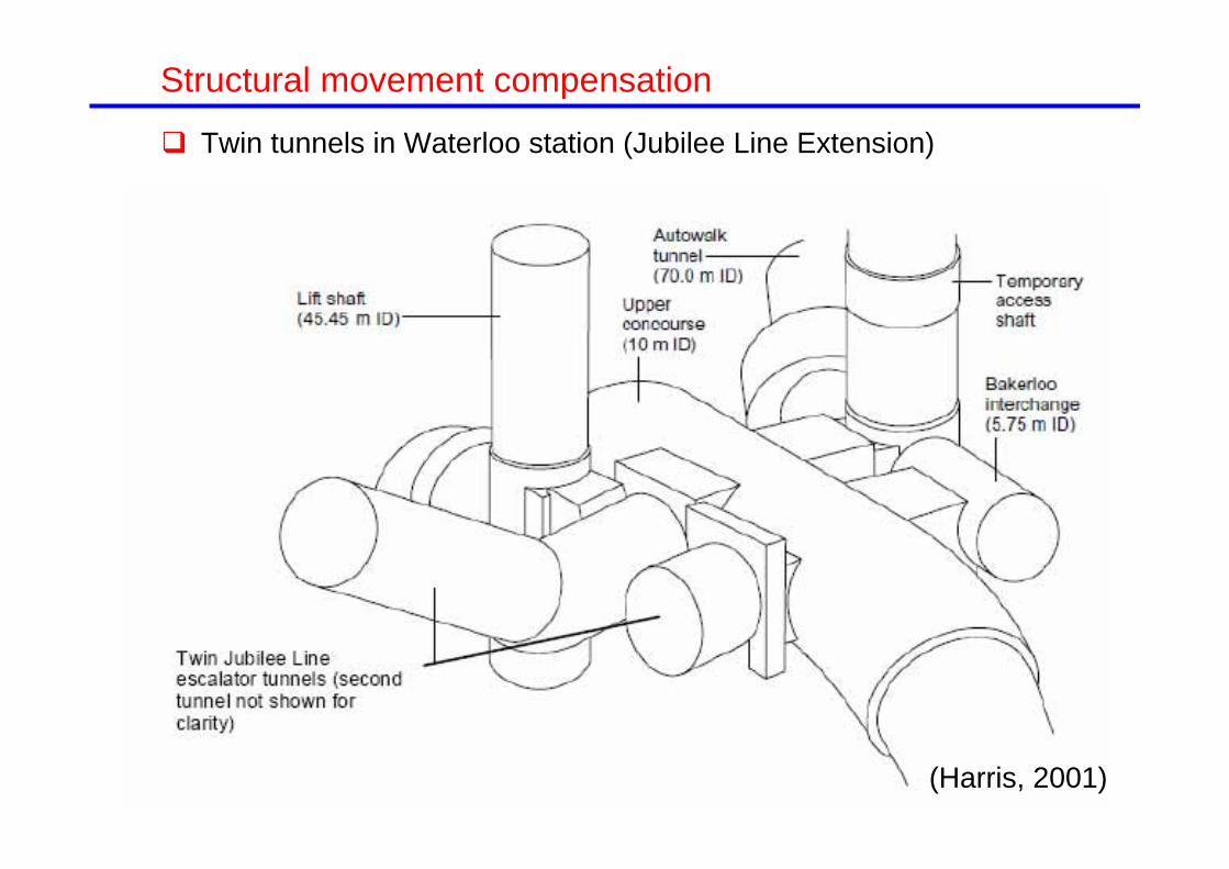
Structural movement compensation
Twin tunnels in Waterloo station (Jubilee Line Extension)
(Harris, 2001)

Cross section
Structural movement compensation
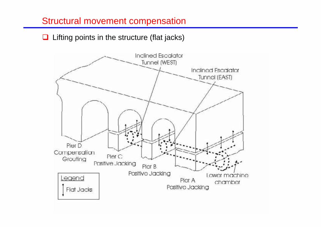
Lifting points in the structure (flat jacks)
Structural movement compensation

Low level tunnels constructedUpper level tunnels
constructed
-0.01
0
0.01
0.02
0.03
0.04
0.05
01/0
1/19
95
02/0
3/19
95
01/0
5/19
95
30/0
6/19
95
29/0
8/19
95
28/1
0/19
95
27/1
2/19
95
25/0
2/19
96
25/0
4/19
96
24/0
6/19
96
23/0
8/19
96
22/1
0/19
96
21/1
2/19
96
19/0
2/19
97
20/0
4/19
97
Settl
emen
t (m
)
Pier A North (above jacks)
Pier A North (below jacks)
Low level tunnelsconstructed Upper level tunnelsconstructed
Settlements below the jacks
Settlements above the jacks
Structural movement compensation
Twin tunnels in Waterloo station (Jubilee Line Extension)

Medium to coarse sands
Gravels with sand/silt matrix
SiltSilty gravel
Tunnel
Passage of Line 9 below an urban motorway
Structural movement compensation

B-10 motorway
Structural movement compensation

Distribution of vertical movements measured in subhorizontal inclinometers
B-10 motorway
Structural movement compensation

Surface and structure settlements
B-10 motorway
Central pierAbutment wall
-50
-40
-30
-20
-10
0
10
05/1
3/20
04
06/0
2/20
04
06/2
2/20
04
07/1
2/20
04
08/0
1/20
04
08/2
1/20
04
09/1
0/20
04
Time
Vert
ical
dis
plac
emen
t [m
m]
StructureSoil surface
Pas
sage
of E
PB
Micropiles
Jacking
-50
-40
-30
-20
-10
0
10
05/1
3/20
04
06/0
2/20
04
06/2
2/20
04
07/1
2/20
04
08/0
1/20
04
08/2
1/20
04
09/1
0/20
04
Time
Vert
ical
dis
plac
emen
t [m
m]
StructureSoil surface
Pass
age
of E
PB
Micropiles
Jacking
Structural movement compensation

Introduction Ground movements generated by tunnelling Procedures for ground movement control
General Tunnelling procedure (TBMs) Screen (curtain) walls Structural movement compensation Compensation grouting
Final remarks
Outline
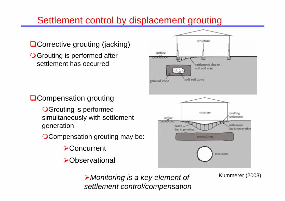
Settlement control by displacement grouting
Corrective grouting (jacking)Grouting is performed after
settlement has occurred
Compensation groutingGrouting is performed simultaneously with settlement generationCompensation grouting may be:
ConcurrentObservational
Kummerer (2003)Monitoring is a key element of settlement control/compensation

Types of groutingCompaction grouting
Injection of stiff high viscosity grout
Harris (2001)
Fracture grouting Injection of low viscosity grout
at pressures that cause fracturing
Intrusion grouting Injection of a fluid grout with a
high solids content. Solids remain near point of injection but limited fracturing

Fracture groutingTAM (sleeve) grouting
Harris (2001)

Compensation grouting
Harris (2001)
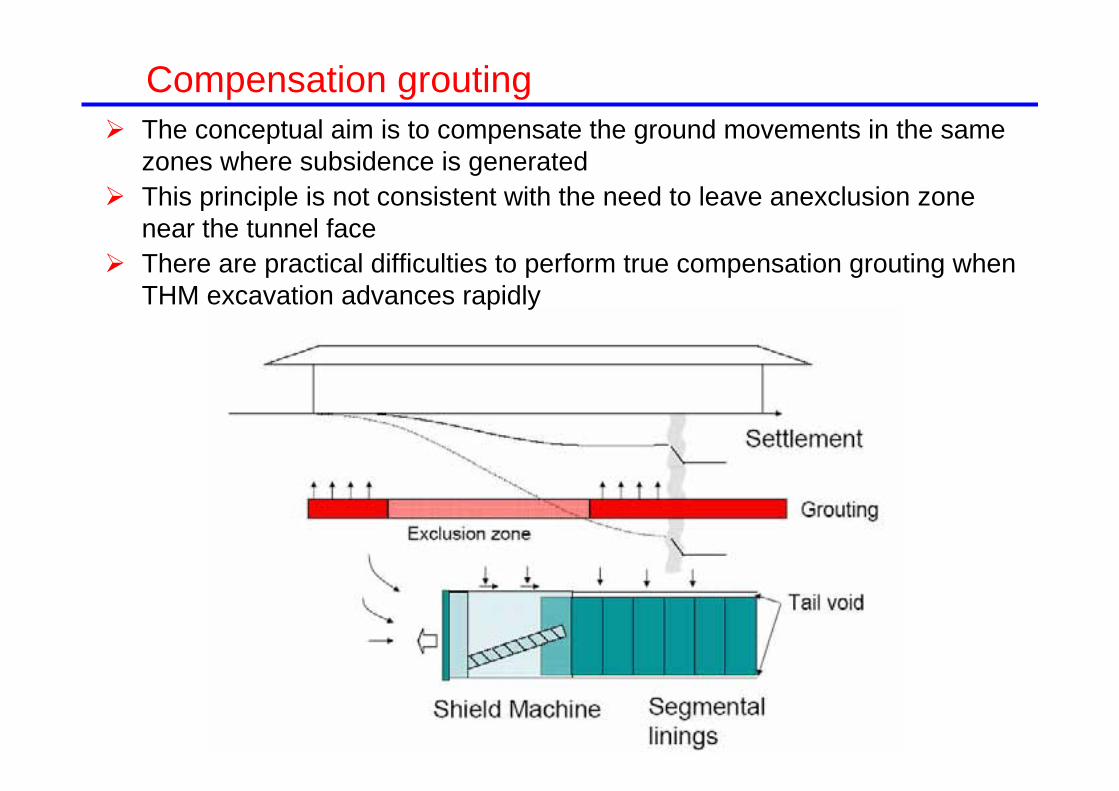
The conceptual aim is to compensate the ground movements in the same zones where subsidence is generated
This principle is not consistent with the need to leave anexclusion zone near the tunnel face
There are practical difficulties to perform true compensation grouting when THM excavation advances rapidly
Compensation grouting

Compaction grouting Bolton Hill Tunnels, Baltimore (Baker et al, 1983) Minneapolis tunnel (Cording et al., 1989) By the 1990’s compensation using compaction grouting well
established in the US (Littlejohn, 2003)
Fracture grouting Essen in 1986 (Chambosse & Osterbein, 2001) Vienna metro (Pototschnik, 1992) Other tunnels in Germany & Austria (e.g. Raabe, 1989) First used in UK in Waterloo station, 1992 (Mair & Hight, 1994) Extensive use in Jubilee extension line, London (well
documented; Burland, Standing & Jardine eds.) Used extensively: Lisbon, Porto, Madrid, Barcelona, Antwerp and
many others (also sometimes used in the US)
The term compensation grouting Apparently coined by D.W. Hight (GCG) (Mair, 1994)
Compensation grouting: a bit of history

Compaction grouting Better control of grout
extension More robust with respect to
implementation parameters Repeat grouting requires
redrilling Higher injection pressures Creates a smaller region of
pore pressure increase Dominant in the US
Compaction grouting vs. Fracture grouting
Fracture grouting Little control of fracture
extension and direction Multiple injection is
straightforward (TAM grouting)
Lower efficiency? Lower injection pressures Creates a larger region of
pore pressure increase Dominant in the Europe
Compensation grouting
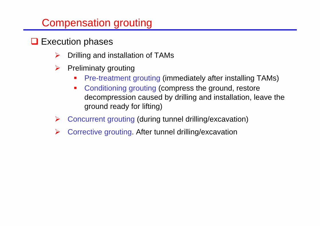
Execution phases Drilling and installation of TAMs
Preliminaty grouting Pre-treatment grouting (immediately after installing TAMs) Conditioning grouting (compress the ground, restore
decompression caused by drilling and installation, leave the ground ready for lifting)
Concurrent grouting (during tunnel drilling/excavation)
Corrective grouting. After tunnel drilling/excavation
Compensation grouting

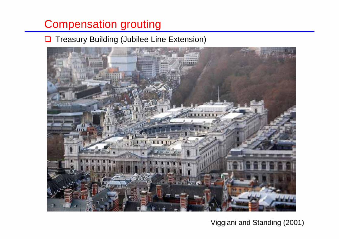
Treasury Building (Jubilee Line Extension)
Compensation grouting
Viggiani and Standing (2001)

Viggiani and Standing (2001)Plan view
Treasury Building (Jubilee Line Extension)
Compensation grouting
Treasury Building (Jubilee Line Extension)
Compensation grouting
Viggiani and Standing (2001)

01020304050distance from corner of ICE
Treasury
made ground
London Clay
shaf
t 3/2G
reat
Geo
rge
St.
eastbound
westbound
array of TAMs -15.5 m (89.5 m PD)In
stitu
tion
of C
ivil
Eng
inee
rs(IC
E)
-23 m(82 m PD)
-32 m(73 m PD)
Terrace Gravel
0.00
-7.00
-11.0
1 23
45
6789
101112
13
14
1516
1718
19
123
4
56
7
8 9 10 11 12 13
141516
171819
2021222324
2526272829
30
31
32
33
34353637
ICE
shaft 3/2
TREASURY1
2
3
4
5
6
7 8 9
10
11
12
13
14
15
16
17
18 1920 21
2223
2425
262728
2930
3132
3334
3536
373839404142
4344
45
46474849
5051
525354
555657
5859
60
61
62
63
64
65
66
67
68
69
70
71
72
Viggiani and Standing (2001)
Cross section
TAM array
Treasury Building (Jubilee Line Extension)
Compensation grouting
2 x 5m dia. Tunnels excavated with open-face shield

01020304050distance from corner of ICE
Treasury
made ground
London Clay
shaf
t 3/2G
reat
Geo
rge
St.
eastbound
westbound
array of TAMs -15.5 m (89.5 m PD)
Inst
itutio
n of
Civ
il E
ngin
eers
(ICE)
-23 m(82 m PD)
-32 m(73 m PD)
Terrace Gravel
0.00
-7.00
-11.0
eastboundwestbound TREASURY
ICE
Treasury Building (Jubilee Line Extension)
Location of levelling points
Compensation grouting

01020304050distance from corner of ICE
Treasury
made ground
London Clay
shaf
t 3/2G
reat
Geo
rge
St.
eastbound
westbound
array of TAMs -15.5 m (89.5 m PD)
Inst
itutio
n of
Civ
il E
ngin
eers
(ICE)
-23 m(82 m PD)
-32 m(73 m PD)
Terrace Gravel
0.00
-7.00
-11.0
eastboundwestbound TREASURY
ICE
Viggiani, 2001
Contours of grouting intensity (l/m2)
Observational grouting performed after drilling West tunnel
Treasury Building (Jubilee Line Extension)
Compensation grouting
GEF = 0.3-0.5 (0.7 in the final stage)

100 80 60 40 20 0distance along façade (m)
-30
-20
-10
0
verti
cal d
ispl
acem
ent (
mm
)
100 80 60 40 20 0distance along façade (m)
100 80 60 40 20 0distance along façade (m)
-30
-20
-10
0
verti
cal d
ispl
acem
ent (
mm
)
100 80 60 40 20 0distance along façade (m)
tunnel face advance
tunnel face advance
westbound - without compensation grouting
eastbound - with compensation grouting
after westbound observational grouting
long term
Viggiani and Standing (2001)
Treasury Building (Jubilee Line Extension)
Settlements
West tunnelNo compensation
grouting
West tunnelCorrective grouting
East tunnelWith compensation
grouting
Long term settlements
Compensation grouting
Transitory movements more severe
wellswells
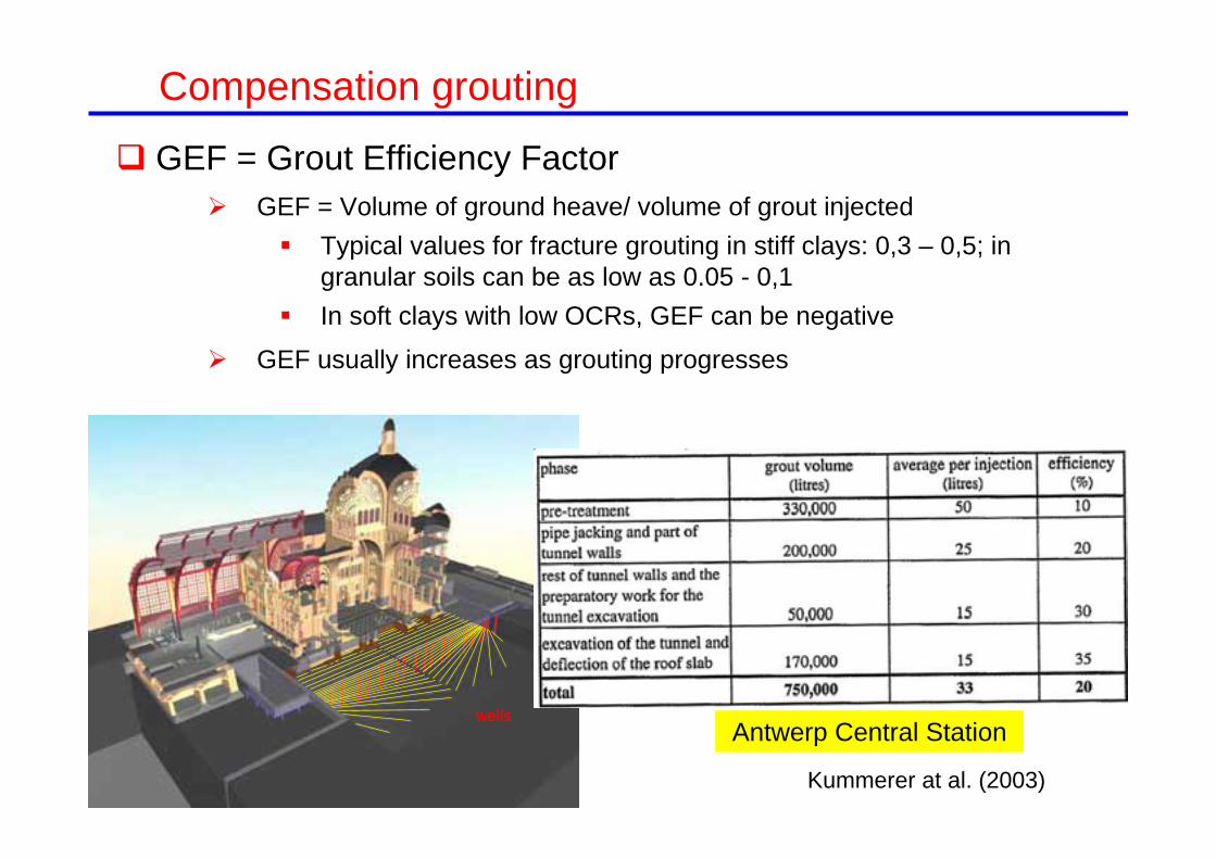
Kummerer at al. (2003)
Antwerp Central Station
GEF = Grout Efficiency Factor GEF = Volume of ground heave/ volume of grout injected
Typical values for fracture grouting in stiff clays: 0,3 – 0,5; in granular soils can be as low as 0.05 - 0,1
In soft clays with low OCRs, GEF can be negative
GEF usually increases as grouting progresses
Compensation grouting
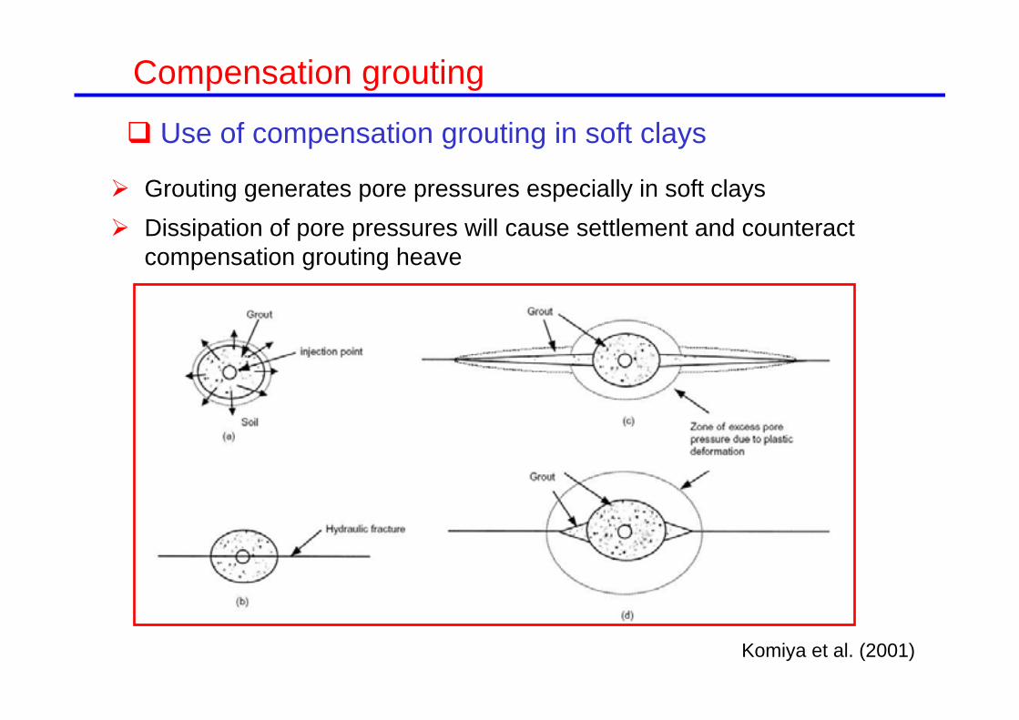
Grouting generates pore pressures especially in soft clays Dissipation of pore pressures will cause settlement and counteract
compensation grouting heave
Use of compensation grouting in soft clays
Komiya et al. (2001)
Compensation grouting

Compensation grouting trial in Singapore marine clay (Shirlaw et al., 1999)
Use of compensation grouting in soft clays
Compensation grouting

Compensation grouting trial in Singapore marine clay (Shirlaw et al., 1999)
Use of compensation grouting in soft clays
Compensation grouting

Compensation grouting trial in Singapore marine clay (Shirlaw et al., 1999)
Use of compensation grouting in soft clays
Compensation grouting

2
max 32 lDs Vi
Compensation grouting

Juan Valera road
Compensation grouting

Juan Valera road
Compensation grouting

Juan Valera road
W.T.
W.T.
Silt with sand and gravel
Gravel and coarse sand
Silt with sand and gravel
Grouting wellGrouting well
Grouting boreholes
TUNNEL
Compensation grouting

Rodio (2005)
Compensation grouting

Compensation grouting
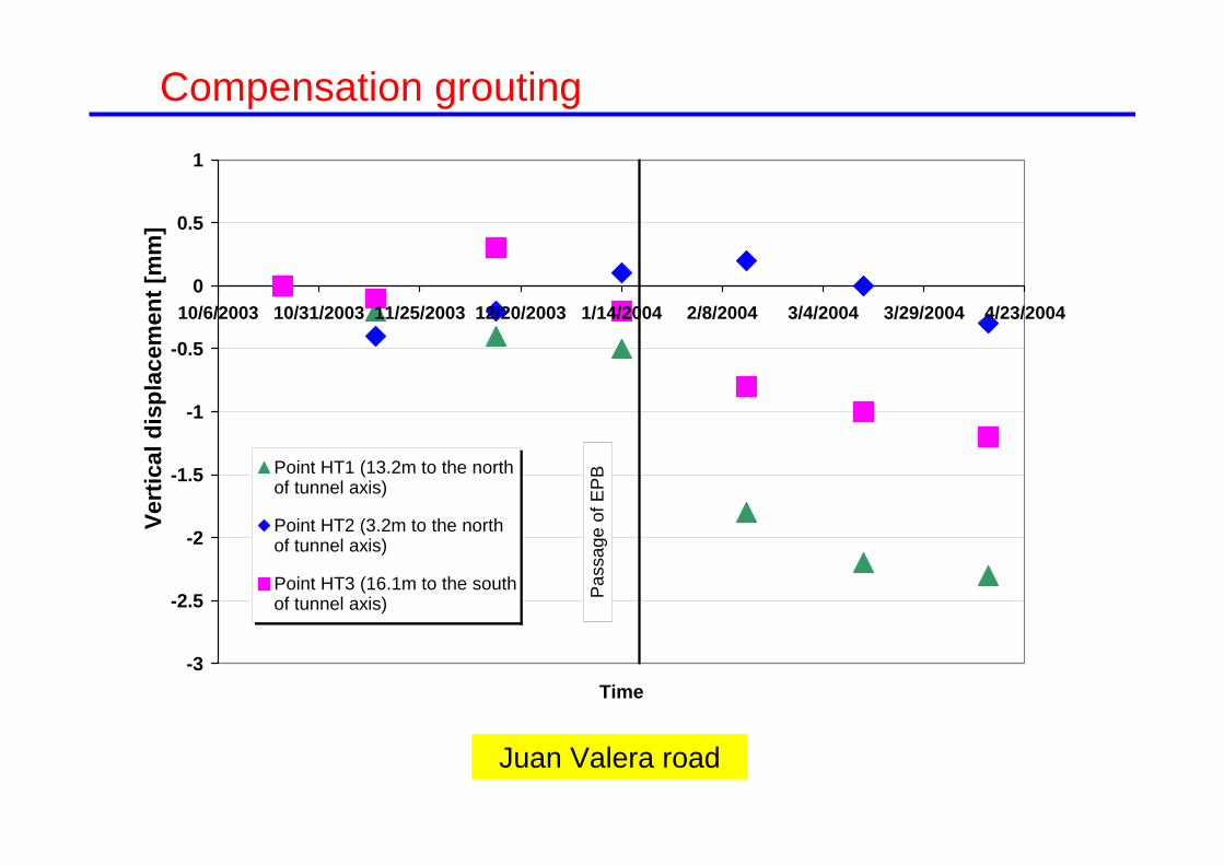
Juan Valera road
-3
-2.5
-2
-1.5
-1
-0.5
0
0.5
1
10/6/2003 10/31/2003 11/25/2003 12/20/2003 1/14/2004 2/8/2004 3/4/2004 3/29/2004 4/23/2004
Time
Point HT1 (13.2m to the northof tunnel axis)
Point HT2 (3.2m to the northof tunnel axis)
Point HT3 (16.1m to the southof tunnel axis)
Vert
ical
dis
plac
emen
t [m
m]
Pas
sage
of E
PB
Compensation grouting

Juan Valera street
0
5
10
15
20
25
30
-10 -5 0 5 10 15 20Vertical displacement [mm]
Dep
th [m
]
At 9.1 m from the centrelineOn the tunnel centreline
Settlements
Compensation grouting

Existing Napoli-Milano rail link on masonry viaduct
Three strings of water level settlement gauges
17.9m10.6m
Tunnel
9.1m
Silt and clay
Made Ground
Sand Gravel
SandSand
GravelGravel
Made Ground
As-built extent of treatment zone
Bologna viaduct and soil profile
Compensation grouting
Acknowledgments to R.J. Mair
Viaduct 112 m long, 11m wide

Bologna viaductCompensation grouting

60.157.7
Temporary pit
59.4
Existing Napoli-Milano rail link on masonry viaduct
Treatment zone
Two layers of curved TAMs
Tunnel 1 Tunnel 2Scale
0 10m
42.03.0m4.4m
1.5m
Pigorini et al (2009)
Cross section
Compensation grouting
Vertical control 1m, horizontal control 0.5m for a 60 m long borehole
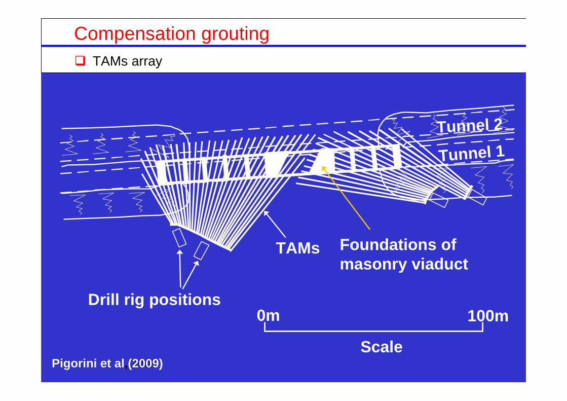
Foundations of masonry viaduct
Tunnel 1Tunnel 2
TAMs
Drill rig positions0m 100m
ScalePigorini et al, 2009Pigorini et al (2009)
TAMs array
Compensation grouting
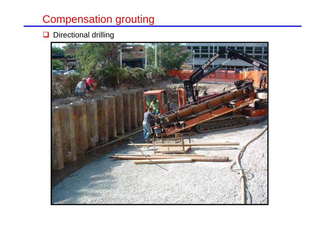
Directional drilling
Compensation grouting

Grouting
Compensation grouting

Distribution of grouting volumes
Compensation grouting

0
40
80
120
28/06/05 30/06/05 02/07/05 04/07/05 06/07/05
Time
Gro
ut v
olum
e (m
3 )
0.0%
0.4%
0.8%
1.2%
Gro
ut (%
of e
xcav
ated
vol
)Cumulative Grout Vol
% Grout vol/ Excavated vol
3300
3350
3400
3450
3500
28/06/05 30/06/05 02/07/05 04/07/05 06/07/05
Cha
inag
e (m
)Cumulative grout vol% Grout vol/ Excavated vol
Gro
ut v
olum
e (m
3 )C
hain
age
(m)
Gro
ut (%
of e
xcav
ated
vol
)
Time
0
120
80
40
28/6/05 30/6/05 02/7/0504/7/05
06/7/05
28/6/05 30/6/05 02/7/05 04/7/05 06/7/05
0.0%
0.4%
0.8%
1.2%
3500
3400
3300
Viaduct + 4m border
Volume loss 0.2%
Pigorini et al (2009)
Grout volume and progress of TBM1
Compensation grouting
GEF=0.33-0.50

-18-14-10-6-22
3310333033503370339034103430Chainage (m)
Settl
emen
t (m
m)
PredictedVL=0.2%
-18-14-10-6-22
3310333033503370339034103430Chainage (m)
Settl
emen
t (m
m)
West
East
PredictedVL=0.2%
0
50
100
Gro
ut
(l/m
2 )
Differential settlement limits between piers
1:3000 Grouting trigger1:1000 Contractual limit
Pigorini et al (2009)
No grouting VL=0.2%
Evolución de asientos
Compensation grouting

Barcelona Metro: Line 9 Piled buildings
Ferran Soldevila street
Compensation grouting

TUNNEL
Barcelona Metro: Line 9 Piled buildings
Compensation grouting

Conditioning grouting
Compensation grouting

Conditioning grouting
Compensation grouting

Westminster station
Compensation grouting

Westminster station
Compensation grouting

34m
Inyecciones de compensación Westminster station
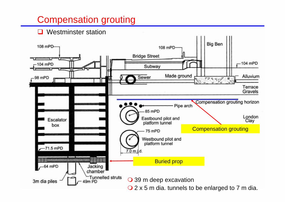
Buried prop
Compensation grouting
Westminster station
Compensation grouting
39 m deep excavation 2 x 5 m dia. tunnels to be enlarged to 7 m dia.


TAMs array
Westminster stationCompensation grouting

Big Ben
Westminster station
Compensation grouting

H = 55m
HΔ
= Tilt
Inyecciones de compensación Westminster station
Clock Tower tilt
Δ= Tilt H (H=55m)
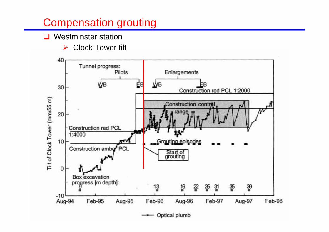
Compensation grouting Westminster station
Clock Tower tilt
Final remarks Control of ground movements is an absolute requirement when tunnelling in
urban areas There is an enhanced sensibility of public opinion concerning these
issues The most effective measure for the control of ground movements is the
selection of an adequate construction procedure and a good control of the works
Screen (curtain) walls are an efficient way of ground movement control when the tunnels are not excavated below buildings
Compensation grouting is an efficient way of ground movement control when the tunnels are excavated below buildings There are however uncertainties over the behaviour mechanisms and
control methods Whenever possible, acting directly on the structure leads to a better control
when correcting the effect of ground movements Often the control measured also generate additional ground movements
It is not recommended, therefore, to try to reduce ground movements to negligible values