nurbs-based finite element analysis of functionally graded … · 2013-12-27 · keywords:...
TRANSCRIPT

NURBS-based finite element analysis of functionally graded plates: static bending,
vibration, buckling and flutter
Navid Valizadeha,1, Sundararajan Natarajanb,2,∗, Octavio A Gonzalez-Estradac,3, Timon Rabczuka,4, TinhQuoc Buid,5, Stephane PA Bordasc,6
aInstitute of Structural Mechanics, Bauhaus-Universitat Weimar, Marienstraße, WeimarbSchool of Civil and Environmental Engineering, The University of New South Wales, Sydney, Australia
cInstitute of Mechanics and Advanced Materials, Cardiff University, Cardiff, UKdChair of Structural Mechanics, Department of Civil Engineering, University of Siegen, Siegen, Germany
Abstract
In this paper, a non-uniform rational B-spline based iso-geometric finite element method is used to study the
static and dynamic characteristics of functionally graded material (FGM) plates. The material properties are
assumed to be graded only in the thickness direction and the effective properties are computed either using
the rule of mixtures or by Mori-Tanaka homogenization scheme. The plate kinematics is based on the first
order shear deformation plate theory (FSDT). The shear correction factors are evaluated employing the energy
equivalence principle and a simple modification to the shear correction factor is presented to alleviate shear
locking. Static bending, mechanical and thermal buckling, linear free flexural vibration and supersonic flutter
analysis of FGM plates are numerically studied. The accuracy of the present formulation is validated against
available three-dimensional solutions. A detailed numerical study is carried out to examine the influence of
the gradient index, the plate aspect ratio and the plate thickness on the global response of functionally graded
material plates.
∗Corresponding [email protected]
Preprint submitted to Elsevier November 1, 2012

Keywords: isogeometric analysis, functionally graded, Reissner Mindlin plate, gradient index, Shear locking,
finite elements, partition of unity, free vibration, buckling, flutter, boundary conditions
1. Introduction
Since its introduction to decrease the thermal stresses in propulsion systems and in airframes for space appli-
cation [1], functionally graded materials (FGMs) have led researchers to investigate the structural behaviour of
such structures. FGMs are considered to be an alternative for certain class of aerospace structures exposed to
high temperature environment. FGMs are characterized by a smooth transition from one material to another,
thus circumventing high inter-laminar shear stresses and de-lamination that persists in laminated composites.
Thus, for structural integrity, FGMs have advantages over the fiber-matrix composites.
1.1. Background
The investigation of the static and the dynamic behaviour of FGM structures is fairly well covered in the
literature. Some of the important contributions are discussed here. Different plate theories, viz, FSDT [2, 3, 4],
second and other higher order accurate theory [5, 6, 7] have been used to describe plate kinematics. Existing
approaches in the literature to study plate and shell structures made up of FGMs uses finite element method
based on Lagrange basis functions [2, 8, 4], meshfree methods [5, 6]. All existing approaches show shear locking
when applied to thin plates. Different techniques by which the locking phenomenon can be suppressed include:
• Retain the original interpolations and subsequently use an optimal integration rule for evaluating the
bending and the shear terms;
• Mixed interpolation technique [9];
• Use field redistributed substitute shape functions [10, 11];
• Discrete shear gap method [12];
2

• Stabilized conforming nodal integration [13], i.e., strain smoothing, SFEM [14, 15].
• Use p-adaptivity, for example Moving Least Square approximations [16].
He et al., [17] presented a finite element formulation based on thin plate theory for the vibration control of FGM
plates with integrated piezoelectric sensors and actuators under mechanical load, whereas Liew et al., [18] have
analyzed the active vibration control of plates subjected to a thermal gradient using shear deformation theory.
The parametric resonance of FGM plates is discussed in [19] by Ng et al., based on Hamilton’s principle and
the assumed mode technique. Yang and Shen [20, 3] have analyzed the dynamic response of thin FGM plates
subjected to impulsive loads using a Galerkin Procedure coupled with modal superposition methods, whereas,
by neglecting the heat conduction effect, such plates and panels in thermal environments have been examined
based on shear deformation with temperature dependent material properties [3]. The static deformation and
vibration of FGM plates based on higher-order shear deformation theory is studied by Qian et al., [5] using the
meshless local Petrov-Galerkin method (MLPG) and Natarajan and Ganapathi [7] using shear flexible elements.
Matsunaga [21] presented analytical solutions for simply supported rectangular FGM plates based on second-
order shear deformation theory, whereas, three dimensional solutions are proposed in [22, 23] for vibrations of
simply supported rectangular FGM plates. Reddy [2] presented finite element solutions for the dynamic analysis
of FGM plates and Ferreira et al., [6] performed dynamic analysis of FGM plates based on higher order shear and
normal deformable plate theory using MLPG. Birman [24] and Javaheri and Eslami [25] have studied buckling
of FGM plates subjected to in-plane compressive loading. Woo et al., [26] analyzed the thermo-mechanical
postbuckling behaviour of plates and shallow cylindrical FGM panels using a classical theory. Ganapathi et
al., [8], using a Co shear flexible quadrilateral element, studied buckling of non-rectangular FGM plates under
mechanical and thermal loads. Prakash and Ganapathi [27] studied the linear flutter characteristics of FGM
panels exposed to supersonic flow. Haddadpour et al., [28] and Sohn and Kim [29, 30] investigated the nonlinear
aspects of flutter characteristics using the finite element method. FGM plates, like other plate structures, may
develop flaws. Recently, Yang and Chen [31] and Kitipornchai et al., [32] studied the dynamic characteristics
3

of FGM beams with an edge crack. Natarajan et al., [33, 34] and Baiz et al., [35] studied the influence of the
crack length on the free flexural vibrations of FGM plates using the XFEM and smoothed XFEM, respectively.
1.2. Approach
The main objective of this paper is to investigate the potential of NURBS based iso-geometric finite element
methods to study the static and dynamic characteristics of Reissner-Mindlin plates. The present formulation
also suffers from shear locking when lower order NURBS functions are used as basis functions. da Vaiga et
al., [36] showed that the shear locking phenomena can be suppressed by using higher order NURBS functions.
A similar approach was employed to suppress shear locking in the element-free Galerkin method [37]. In this
paper, we propose a simple technique to suppress shear locking, which relies on the introduction of an artificial
shear correction factor [38] when lower order NURBS basis functions are used. The drawback of this approach
is that the shear correction factor is problem dependent.
1.3. Outline
The paper is organized as follows. A brief overview on functionally graded materials and Reissner-Mindlin plate
theory is presented in the next section. Section 3 presents an overview of NURBS basis functions and a simple
correction to the shear terms to alleviate shear locking. The efficiency of the present formulation, numerical
results and parametric studies are presented in Section 5, followed by concluding remarks in the last section.
2. Theoretical Formulation
2.1. Functionally graded material
A rectangular plate made of a mixture of ceramic and metal is considered with the coordinates x, y along the in-
plane directions and z along the thickness direction (see Figure (1)). The material on the top surface (z = h/2)
of the plate is ceramic rich and is graded to metal at the bottom surface of the plate (z = −h/2) by a power
4

law distribution. The effective properties of the FGM plate can be computed by using the rule of mixtures or
by employing the Mori-Tanaka homogenization scheme.
Let Vi(i = c,m) be the volume fraction of the phase material. The subscripts c and m refer to ceramic and
metal phases, respectively. The volume fraction of ceramic and metal phases are related by Vc+ Vm = 1 and Vc
is expressed as:
Vc(z) =
(
2z + h
2h
)n
(1)
where n is the volume fraction exponent (n ≥ 0), also known as the gradient index. The variation of the
composition of ceramic and metal is linear for n =1, the value of n = 0 represents a fully ceramic plate and any
other value of n yields a composite material with a smooth transition from ceramic to metal.
Rule of mixtures
Based on the rule of mixtures, the effective property of a FGM is computed using the following expression:
P = PcVc + PmVm (2)
Mori-Tanaka homogenization method
Based on the Mori-Tanaka homogenization method, the effective Young’s modulus and Poisson’s ratio are
computed from the effective bulk modulus K and the effective shear modulus G as [4]
Keff −Km
Kc −Km=
Vc
1 + Vm3(Kc−Km)3Km+4Gm
Geff −GmGc −Gm
=Vc
1 + Vm(Gc−Gm)(Gm+f1)
(3)
5

where
f1 =Gm(9Km + 8Gm)
6(Km + 2Gm)(4)
The effective Young’s modulus Eeff and Poisson’s ratio νeff can be computed from the following relations:
Eeff =9KeffGeff
3Keff +Geff
νeff =3Keff − 2Geff
2(3Keff +Geff)(5)
The effective mass density ρ is computed using the rule of mixtures. The effective heat conductivity κeff and
the coefficient of thermal expansion αeff is given by:
κeff − κmκc − κm
=Vc
1 + Vm(κc−κm)
3κm
αeff − αmαc − αm
=
(
1Keff
− 1Km
)
(
1Kc
− 1Km
) (6)
Temperature distribution through the thickness
The temperature variation is assumed to occur in the thickness direction only and the temperature field is
considered to be constant in the xy-plane. In such a case, the temperature distribution along the thickness can
be obtained by solving a steady state heat transfer problem:
− d
dz
[
κ(z)dT
dz
]
= 0, T = Tc at z = h/2; T = Tm at z = −h/2 (7)
6

The solution of Equation (7) is obtained by means of a polynomial series [39] as
T (z) = Tm + (Tc − Tm)η(z, h) (8)
where,
η(z, h) =1
C
[
(
2z + h
2h
)
− κcm(n+ 1)κm
(
2z + h
2h
)n+1
+
κ2cm(2n + 1)κ2m
(
2z + h
2h
)2n+1
− κ3cm(3n+ 1)κ3m
(
2z + h
2h
)3n+1
+κ4cm
(4n+ 1)κ4m
(
2z + h
2h
)4n+1
− κ5cm(5n + 1)κ5m
(
2z + h
2h
)5n+1]
;
(9)
C = 1− κcm(n+ 1)κm
+κ2cm
(2n + 1)κ2m− κ3cm
(3n+ 1)κ3m
+κ4cm
(4n+ 1)κ4m− κ5cm
(5n+ 1)κ5m
(10)
2.2. Reissner-Mindlin Plates
The displacements u, v, w at a point (x, y, z) in the plate (see Figure (1)) from the medium surface are expressed
as functions of the mid-plane displacements uo, vo, wo and independent rotations θx, θy of the normal in yz and
xz planes, respectively, as:
u(x, y, z, t) = uo(x, y, t) + zθx(x, y, t)
v(x, y, z, t) = vo(x, y, t) + zθy(x, y, t)
w(x, y, z, t) = wo(x, y, t) (11)
7

where t is the time.
z
x
y
a
b
h
(a)
ψ
y
y′
x, x′
a
b
(b)
Figure 1: (a) coordinate system of a rectangular FGM plate, (b) Coordinate system of a skew plate
The strains in terms of mid-plane deformation can be written as:
ε =
εp
0
+
zεb
εs
(12)
The midplane strains εp, bending strain εb, shear strain εs in Equation (12) are written as:
εp =
uo,x
vo,y
uo,y + vo,x
, εb =
θx,x
θy,y
θx,y + θy,x
,
εs =
θx + wo,x
θy + wo,y
. (13)
where the subscript ‘comma’ represents the partial derivative with respect to the spatial coordinate succeeding
8

it. The membrane stress resultants N and the bending stress resultants M can be related to the membrane
strains, εp and bending strains εb through the following constitutive relations:
N =
Nxx
Nyy
Nxy
= Aεp +Bεb
M =
Mxx
Myy
Mxy
= Bεp +Dbεb (14)
where the matrices A = Aij,B = Bij and Db = Dij ; (i, j = 1, 2, 6) are the extensional, bending-extensional
coupling and bending stiffness coefficients and are defined as:
Aij, Bij , Dij =
∫ h/2
−h/2Qij
1, z, z2
dz (15)
Similarly, the transverse shear force Q = Qxz, Qyz is related to the transverse shear strains εs through the
following equation:
Qij = Eijεs (16)
where Eij =∫ h/2−h/2Qυiυj dz; (i, j = 4, 5) is the transverse shear stiffness coefficient, υi, υj is the transverse shear
coefficient for non-uniform shear strain distribution through the plate thickness. The stiffness coefficients Qij
are defined as:
9

Q11 = Q22 =E(z)
1− ν2; Q12 =
νE(z)
1− ν2; Q16 = Q26 = 0
Q44 = Q55 = Q66 =E(z)
2(1 + ν)(17)
where the modulus of elasticity E(z) and Poisson’s ratio ν are given by Equation (5). The thermal stress
resultant Nth and the moment resultant Mth are:
Nth =
N thxx
N thyy
N thxy
=
h/2∫
−h/2
Qijα(z, T )
1
1
0
∆T (z) dz
Mth =
M thxx
M thyy
M thxy
=
h/2∫
−h/2
Qijα(z, T )
1
1
0
∆T (z) z dz
(18)
where the thermal coefficient of expansion α(z, T ) is given by Equation (6) and ∆T (z) = T (z) − To is the
temperature rise from the reference temperature and To is the temperature at which there are no thermal
strains. The strain energy function U is given by:
U(δ) =1
2
∫
Ω
εTpAεp + ε
TpBεb + ε
Tb Bεp + ε
Tb Dεb + ε
Ts Eεs
dΩ (19)
where δ = u, v, w, θx, θy is the vector of the degree of freedom associated to the displacement field in a finite
element discretization. Following the procedure given in [40], the strain energy function U given in Equation
10
(19) can be rewritten as:
U(δ) =1
2δTKδ (20)
where K is the linear stiffness matrix. The kinetic energy of the plate is given by:
T (δ) =1
2
∫
Ω
p(u2o + v2o + w2o) + I(θ2x + θ2y)
dΩ (21)
where p =∫ h/2−h/2 ρ(z) dz, I =
∫ h/2−h/2 z
2ρ(z) dz and ρ(z) is the mass density that varies through the thickness of
the plate. When the plate is subjected to a temperature field, this in turn results in in-plane stress resultants,
Nth. The external work due to the in-plane stress resultants developed in the plate under a thermal load is
given by:
V (δ) =
∫
Ω
1
2
[
N thxxw
2,x +N th
yyw2,y + 2N th
xyw,xw,y
]
+
h2
24
[
N thxx
(
θ2x,x + θ2y,x)
+N2yy
(
θ2x,y + θ2y,y)
+ 2N thxy (θx,xθx,y + θy,xθy,y)
]
dΩ
(22)
The governing equations of motion are obtained by writing the Lagrange equations of motion given by:
d
dt
[
∂(T − U)
∂δi
]
−[
∂(T − U)
∂δi
]
= 0, i = 1, 2, · · · , n (23)
The governing equations obtained using the minimization of total potential energy are solved using Galerkin
finite element method. The finite element equations thus derived are:
Static bending:
(K+KG) δ = F (24)
11

Free vibration:
Mδ + (K+KG) δ = 0 (25)
Buckling analysis:
Mechanical Buckling.
(K+ λKG) δ = 0 (26)
Thermal Buckling.
(K+∆TKG) δ = 0 (27)
where δ is the vector of degree of freedom associated to the displacement field in a finite element discretization,
∆T (= Tc − Tm) is the critical temperature difference, λ is the critical buckling load and K, KG are the linear
stiffness and geometric stiffness matrices, respectively. The critical temperature difference is computed using a
standard eigenvalue algorithm.
Flutter analysis: The work done by the applied non-conservative loads is:
W (δ) =
∫
Ω∆pw dΩ (28)
where ∆p is the aerodynamic pressure. The aerodynamic pressure based on first-order, high Mach number
approximation to linear potential flow is given by:
∆p =ρaU
2a
√
M2∞
− 1
[
∂w
∂xcos θ′ +
∂w
∂ysin θ′ +
(
1
Ua
)
M2∞
− 2
M2∞
− 1
∂w
∂t
]
(29)
where ρa, Ua,M∞ and θ′ are the free stream air density, velocity of air, Mach number and flow angle, respectively.
12

The static aerodynamic approximation for Mach numbers between√2 and 2 is [41]:
∆p =ρaU
2a
√
M2∞
− 1
[
∂w
∂xcos θ′ +
∂w
∂ysin θ′
]
(30)
Substituting Equation (20) - (28) in Lagrange’s equations of motion, the following governing equation is obtained:
Mδ + (K+ λA)δ = 0 (31)
After substituting the characteristic of the time function [42] δ = −ω2δ, the following algebraic equation is
obtained:
[(
K+ λA)
− ω2M]
δ = 0 (32)
whereK is the stiffness matrix, M is the consistent mass matrix, λ = ρaU2a√
M2∞−1
, A is the aerodynamic force matrix
and ω is the natural frequency. When λ =0, the eigenvalue of ω is real and positive, since the stiffness matrix
and mass matrix are symmetric and positive definite. However, the aerodynamic matrix A is unsymmetric and
hence complex eigenvalues ω are expected for λ > 0. As λ increases monotonically from zero, two of these
eigenvalues will approach each other and become complex conjugates. In this study, λcr is considered to be the
value of λ at which the first coalescence occurs.
3. Non-Uniform Rational B-Splines
In this study, the finite element approximation uses NURBS basis function. We give here only a brief introduction
to NURBS. More details on their use in FEM are given in [43, 44]. The key ingredients in the construction
of NURBS basis functions are: the knot vector (a non decreasing sequence of parameter values, ξi ≤ ξi+1, i =
0, 1, · · · ,m− 1), the control points, Pi, the degree of the curve p and the weight associated to a control point,
w. The ith B-spline basis function of degree p, denoted by Ni,p is defined as:
13

Ni,0(ξ) =
1 if ξi ≤ ξ ≤ ξi+1
0 else
Ni,p(ξ) =ξ − ξiξi+p − ξi
Ni,p−1(ξ) +ξi+p+1 − ξ
ξi+p+1 − ξi+1Ni+1,p−1(ξ) (33)
A pth degree NURBS curve is defined as follows:
C(ξ) =
m∑
i=0Ni,p(ξ)wiPi
m∑
i=0Ni,p(ξ)wi
(34)
0 0.2 0.4 0.6 0.8 10
0.1
0.2
0.3
0.4
0.5
0.6
0.7
0.8
0.9
1
Ξ
Bas
is f
un
ctio
ns
Figure 2: non-uniform rational B-splines, order of the curve = 3
where Pi are the control points and wi are the associated weights. Figure (2) shows the third order non-uniform
rational B-splines for a knot vector, Ξ = 0, 0, 0, 0, 1/3, 1/3, 1/3, 1/2, 2/3, 1, 1, 1, 1. NURBS basis
functions has the following properties: (i) non-negativity, (ii) partition of unity,∑
iNi,p = 1; (iii) interpolatory
14
at the end points. As the same function is also used to represent the geometry, the exact representation of
the geometry is preserved. It should be noted that the continuity of the NURBS functions can be tailored to
the needs of the problem. The B-spline surfaces are defined by the tensor product of basis functions in two
parametric dimensions ξ and η with two knot vectors, one in each dimension as:
C(ξ, η) =n∑
i=1
m∑
j=1
Ni,p(ξ)Mj,q(η)Pi,j (35)
where Pi,j is the bidirectional control net and Ni,p and Mj,q are the B-spline basis functions defined on the knot
vectors over an m× n net of control points Pi,j . The NURBS surface is then defined by:
C(ξ, η) =
∑ni=1
∑mj=1Ni,p(ξ)Mj,q(η)Pi,jwiwj
w(ξ, η)(36)
where w(ξ, η) is the weighting function. The displacement field within the control mesh is approximated by:
ueo, veo, weo, θex, θey = C(ξ, η)uoJ , voJ , woJ , θxJ , θyJ, (37)
where uoJ , voJ , woJ , θxJ , θyJ are the nodal variables and C(ξ, η) are the basis functions given by Equation (36).
4. Shear Locking
Transverse shear deformations are included in the formulation of Mindlin theory for thick plates. In Mindlin
theory, the transverse normal to the mid surface of the plate before deformation remain straight but not
necessarily normal to the mid surface after deformation. This relaxed the continuity requirement on the assumed
displacement fields. But as the plate becomes very thin, care must be taken in not to violate the following
relationship
∇w + θ = 0 (38)
15

i.e., the shear strain εs must vanish in the domain as the thickness approaches zero.
Artificial shear correction factor
Lower order NURBS basis functions, like any other function, suffer from shear locking when applied to thin
plates. Kikuchi and Ishii [38] introduced an artificial shear correction factor to suppress shear locking in 4-noded
quadrilateral element. In this paper, we employ the same technique to suppress the shear locking syndrome in
lower order NURBS basis functions. The modified shear correction factor is given by:
υe = υ
(
hβle
)2
(
1 +(
hβle
)2n)1/n
(39)
where n, β are positive integers, le is the diameter of the element (=maximum or diagonal length of the element),
h is thickness of the element and υ is the shear correction factor. Here, the shear correction factor obtained
based on energy equivalence principle as outlined in [45, 33] is used.
5. Numerical Examples
In this section, we present the static bending response, free vibration, buckling and flutter analysis of FGM
plates using a NURBS based finite element method. The effect of various parameters, viz., material gradient
index n, skewness of the plate ψ, the plate aspect ratio a/b, the plate thickness a/h and boundary conditions on
the global response is numerically studied. The top surface of the plate is ceramic rich and the bottom surface
of the plate is metal rich. The material properties used for the FGM components are listed in Table 1.
Skew boundary transformation
For skew plates supported on two adjacent edges, the edges of the boundary elements may not be parallel to
the global axes (x, y, z). In order to specify the boundary conditions on skew edges, it is necessary to use
the edge displacements (u′o, v′
o, w′
o), etc., in a local coordinate system (x′, y′, z′) (see Figure (1)). The element
16

Table 1: Material properties.
Property Aluminum Zirconia Zirconia Alumina
Al ZrO2-1 ZrO2-2 Al2O3
E (GPa) 70 200 151 380
ν 0.3 0.3 0.3 0.3
κ W/mK 204 2.09 2.09 10.4
α/C 23 ×10−6 10 ×10−6 10 ×10−6 7.2 ×10⁻⁶
ρ kg/m3 2707 5700 3000 3800
matrices corresponding to the skew edges are transformed from global axes to local axes on which the boundary
conditions can be conveniently specified. The relation between the global and local degrees of a particular node
can be obtained through the following transformation [33]
δ = Lgδ′ (40)
where δ and δ′ are the generalized displacement vector in the global and the local coordinate system, respectively.
The nodal transformation matrix for a node I on the skew boundary is given by
Lg =
cosψ sinψ 0 0 0
− sinψ cosψ 0 0 0
0 0 1 0 0
0 0 0 cosψ sinψ
0 0 0 − sinψ cosψ
(41)
where ψ defines the skewness of the plate.
17

5.1. Static Bending
Let us consider a Al/ZrO2 FGM square plate with length-to-thickness a/h = 5, subjected to a uniform load
with fully simply supported (SSSS) and fully clamped (CCCC) boundary conditions. Four different values
for the gradient index (n = 0, 0.5, 1, 2) are considered in this study. The plate is modelled with 4, 8, 16, 24
and 32 control points per side. Tables 2 and 3 summarize the IGA results with quadratic, cubic and quartic
NURBS elements for SSSS and CCCC boundary conditions. It can be seen that for all polynomial orders, the
convergence of the results is quite fast. For cubic and quartic NURBS elements, the convergence is almost
achieved with 16 control points per side. Table 4 compares the results from the present formulation with other
approaches available in the literature [46, 47, 48] and a very good agreement can be observed.
Next, we illustrate the performance of the present isogeometric method for thin plate problems. A simply
supported and a clamped Al/ZrO2-1 square plates subjected to uniform load are considered, while the length-
to-thickness (a/h) varies from 5 to 106 and the gradient index ranges from 0 to 2. Two individual approaches are
employed: one applied the stabilization technique to eliminate shear locking named S-IGA and the other one,
normal IGA, without considering any specific technique for shear locking. The plate is modelled using quadratic
NURBS elements with 13×13 control points. The normalized center deflection wc = 100wcEch3
12(1−ν2)pa4and the
normalized axial stress σxx = σxxh2
pa2at the top surface of the center of the plate for SSSS and CCCC boundary
conditions are depicted in Figures 3 - 4, respectively. It is observed that IGA results are subjected to shear
locking when the plate becomes thin ( a/h > 100). However, the S-IGA results are almost independent of the
length-to-thickness ratio for thin plates. The same observations also reported in [49] for laminated composite
plates. The results using the S-IGA agree very well with those given in [48] using the NS-DSG3 element.
FGM plates under thermo-mechanical loads
Here, the present isogeometric method is verified on FGM plates subjected to thermo-mechanical loads. A simply
supported Al/ZrO2 plate with aluminium at the bottom surface and zirconia at the top surface is considered.
The plate with length a = 0.2 m and thickness h=0.01 m is modelled employing quadratic NURBS elements. For
18

Table 2: The normalized center deflection for fully simply supported Al/ZrO2-1 FGM square plate with a/h = 5, subjected to auniformly distributed load p using IGA. ∗At least 5 control points per side are needed for 1 quartic NURBS element.
Method Number of gradient index, n
Control Points 0 0.5 1 2
Quadratic
4 0.162098 0.218914 0.256018 0.293806
8 0.171617 0.232392 0.271879 0.311459
16 0.171649 0.232439 0.271935 0.311520
24 0.171651 0.232441 0.271938 0.311523
32 0.171651 0.232442 0.271938 0.311523
Cubic
4 0.163329 0.220598 0.257991 0.296053
8 0.171658 0.232452 0.271950 0.311536
16 0.171651 0.232441 0.271938 0.311522
24 0.171651 0.232442 0.271938 0.311523
32 0.171651 0.232442 0.271938 0.311523
Quartic
5∗ 0.172910 0.234167 0.273959 0.313821
8 0.171690 0.232495 0.272000 0.311594
16 0.171651 0.232442 0.271938 0.311523
24 0.171651 0.232442 0.271938 0.311523
32 0.171651 0.232442 0.271938 0.311523
19

Table 3: The normalized center deflection for fully clamped Al/ZrO2-1 FGM square plate with a/h = 5, subjected to a uniformlydistributed load p using IGA. ∗At least 5 control points per side are needed for 1 quartic NURBS element.
Method Number of gradient index, n
Control Points 0 0.5 1 2
Quadratic
4 0.052510 0.06818 0.079306 0.093421
8 0.075831 0.101036 0.117946 0.136557
16 0.076017 0.101305 0.118264 0.136905
24 0.076024 0.101315 0.118276 0.136918
32 0.076025 0.101316 0.118278 0.136920
Cubic
4 0.056337 0.07342 0.085447 0.100403
8 0.076031 0.101324 0.118287 0.136931
16 0.076025 0.101316 0.118277 0.136921
24 0.076025 0.101317 0.118278 0.136921
32 0.076026 0.101317 0.118279 0.136921
Quartic
5∗ 0.077690 0.103620 0.120980 0.139973
8 0.076092 0.101409 0.118387 0.137043
16 0.076026 0.101317 0.118279 0.136921
24 0.076026 0.101317 0.118279 0.136921
32 0.076026 0.101317 0.118279 0.136921
20

Table 4: The normalized center deflection for fully clamped Al/ZrO2-1 FGM square plate with a/h = 5, subjected to a uniformlydistributed load p using 13 ×13 control points for various boundary conditions. ∗At least 5 control points per side are needed for 1quartic NURBS element.
Method Number of gradient index, n
Control Points 0 0.5 1 2
SSSS
IGA-Quadratic 0.1717 0.2324 0.2719 0.3115
IGA-Cubic 0.1717 0.2324 0.2719 0.3115
IGA-Quartic 0.1717 0.2324 0.2719 0.3115
NS-DSG3 [48] 0.1721 0.2326 0.2716 0.3107
ES-DSG3 [48] 0.1700 0.2296 0.2680 0.3066
MITC4 [48] 0.1715 0.2317 0.2704 0.3093
kp−Ritz [47] 0.1722 0.2403 0.2811 0.3221
MLPG [46] 0.1671 0.2505 0.2905 0.3280
CCCC
IGA-Quadratic 0.0760 0.1013 0.1183 0.1369
IGA-Cubic 0.0760 0.1014 0.1183 0.1369
IGA-Quartic 0.0760 0.1014 0.1183 0.1369
NS-DSG3 [48] 0.0788 0.1051 0.1227 0.1420
ES-DSG3 [48] 0.0761 0.1013 0.1183 0.1370
MITC4 [48] 0.0758 0.1010 0.1179 0.1365
kp−Ritz [47] 0.0774 0.1034 0.1207 0.1404
MLPG [46] 0.0731 0.1073 0.1253 0.1444
21

100
102
104
106
0.4
0.5
0.6
0.7
0.8
0.9
1
a/h
Nor
mal
ized
cen
ter
defle
ctio
n
IGA, n=0S−IGA, n=0IGA, n=0.5S−IGA, n=0.5IGA, n=1SIGA, n=1IGA, n=2S−IGA, n=2
(a)
100
102
104
106
0.2
0.25
0.3
0.35
0.4
0.45
a/h
Nor
mal
ized
cen
ter
stre
ss
IGA, n=0 S−IGA, n=0 IGA, n=0.5 S−IGA, n=0.5 IGA, n=1 SIGA, n=1 IGA, n=2 S−IGA, n=2
(b)
Figure 3: The normalized center deflection, wc and the normalized axial stress σxx as a function of a/h for a simply supportedAl/Zr02-1 FGM square plate subjected to a uniform load, p: (a) normalized center deflection and (b) normalized center stress.
22

100
102
104
106
0
0.05
0.1
0.15
0.2
0.25
0.3
0.35
0.4
a/h
Nor
mal
ized
cen
ter
defle
ctio
n
IGA, n=0 S−IGA, n=0 IGA, n=0.5 S−IGA, n=0.5 IGA, n=1 SIGA, n=1 IGA, n=2 S−IGA, n=2
(a)
100
102
104
106
0
0.05
0.1
0.15
0.2
a/h
Nor
mal
ized
cen
ter
stre
ss
IGA, n=0 S−IGA, n=0 IGA, n=0.5 S−IGA, n=0.5 IGA, n=1 SIGA, n=1 IGA, n=2 S−IGA, n=2
(b)
Figure 4: The normalized center deflection, wc and the normalized axial stress σxx as a function of a/h for a clamped Al/Zr02-1FGM square plate subjected to a uniform load, p: (a) normalized center deflection and (b) normalized center stress.
23

comparison, a mesh with 13 control points per side is used. At first, we study the behaviour of SSSS Al/ZrO2-I
FGM plate under a uniform mechanical load. Figure (5) shows the distributions of the normalized axial stress
through the thickness of the plate computed for different values of the gradient index n. The results are in
excellent agreement with those given in [46, 48]. Figure (6) plots the central deflection wc = 100wcEch3
12(1−ν2)pa4
of the plate with respect to various load parameters, p = pa4/(Emh4), given in the interval [-14, 0] for different
values of the gradient index n. It can be seen that the central deflection of the plate linearly increases with
respect to the load. It is also observed that the central deflection increases with the gradient index k. As
expected, the metallic plate has the largest deflection, while the ceramic plate has the lowest. Note that the
results match well with those given in [48, 50]. Figure (6) shows the normalized axial stress at points on the
vertical line passing through the centroid of simply supported Al/ZrO2-2 FGM square plate subjected to a
uniform mechanical load p. The results agree well with the results reported in [47, 48]. It is observed that
for isotropic plates (i.e, n = 0) the axial stress distribution is linear while it is nonlinear for FGM plates. For
FGM plates, the magnitude of the axial stress at the bottom is less than the one at the top. The maximum
compressive stress at the top surface of the plate has been obtained for the FGM plate with n = 2, whilst the
metallic only or ceramic only plates has the minimum tensile stress at the bottom surface.
FGM plates subjected to thermal loading
Next, we study the behaviour of FGM plates under the thermal loading. A Al/ZrO2-2 FGM plate with length
a = 0.2m and thickness h = 0.01m is considered. The temperature at the top surface of the plate is varied
from 0C to 500C, while the temperature at the bottom surface is maintained at 20C. The temperature of
the stress free state is assumed to be at To = 0C. Figure (7) depicts the non-dimensional center deflection of
the plate under the thermal load. This problem was solved by Zhao and Liew, using the element free kp-Ritz
method [51] and by Xuan et al., [48] using NS-DSG3 elements. The results obtained with our IGA method agree
very well with those given in [51, 48]. From Figure (7), it is observed that the metal plate gives the maximum
deflection because of its high thermal conductivity. The deflection of the FGM plate with the gradient index
24

−0.4 −0.3 −0.2 −0.1 0 0.1 0.2 0.3−0.5
0
0.5
Normalized axial stress
Nor
mal
ized
thic
knes
s
ceramic or metaln=0.5n=1n=2
Figure 5: The normalized axial stress σxx = σxxh2
pL2 at points on the vertical line passing through the centroid of a simply supported
square Al/Zr02 FGM plate subjected to uniform mechanical load p.
n = 1 is minimum. Generally, it can be seen that the deflections of the FGM plates are much lower than those
of isotropic plates (i.e., n = 0), which implies high temperature resistance behaviour of the functionally graded
plates.
Now, we investigate the FGM plate under thermo-mechanical loads. The temperature at the top surface of the
plate is held at 300C (top surface is assumed to be rich in ceramic) and the temperature at the bottom surface
(assumed to be rich in metal) is Tm =20C. Figure (9) shows the center deflection wc = wc/h of the plate with
respect to various load parameters p = pa4/(Emh4) given in the interval -14 ≤ p ≤ 0 for different values of
the gradient index. It can be seen that the central deflection of the plate is completely different from the case
with a purely mechanical loading (see Figure (6)). However, similarly to the case of the FGM plate under pure
mechanical loading, the center deflection of the plate linearly increases with the load. The metallic phase shows
the maximum range of deflection changes and the ceramic plate the least.
Figure (9) plots the distribution of axial stress through the thickness of the plate under the uniform mechanical
25

−14 −12 −10 −8 −6 −4 −2 0−0.7
−0.6
−0.5
−0.4
−0.3
−0.2
−0.1
0
Load parameter
Nor
mal
ized
def
lect
ion
ceramicn=0.5n=1n=2metal
(a)
−0.4 −0.3 −0.2 −0.1 0.0 0.1 0.2 0.3−0.5
0
0.5
Normalized axial stress
Nor
mal
ized
thic
knes
s
ceramicn=0.5n=1n=2metal
(b)
Figure 6: The normalized center deflection wc and the normalized axial stress σxx of a simply supported square Al/Zr02 FGMplate subjected to uniform mechanical load p: (a)The normalized center deflection, wc = wc/hwith p = pa4/(Emh
4) and (b) The
normalized axial stress σxx = σxxh2
pa2 at points on the vertical line passing through the centroid with load p.
26

0 50 100 150 200 250 300 350 400 450 500−0.1
0
0.1
0.2
0.3
0.4
0.5
0.6
Thermal load parameter
Non
−di
men
sion
al d
efle
ctio
n
ceramicn=0.5n=1n=2metal
Figure 7: The normalized center deflection wc = wc/h of a simply supported square Al/ZrO2 FGM plate subjected to thermal load.
−14 −12 −10 −8 −6 −4 −2 0−0.4
−0.3
−0.2
−0.1
0
0.1
0.2
0.3
Load parameter
Nor
mal
ized
def
lect
ion
ceramicn=0.5n=1n=2metal
Figure 8: The normalized center deflection wc = wc/h of a simply supported square Al/ZrO2 FGM plate subjected to thermo-mechanical load.
27

−1.4 −1.2 −1.0 −0.8 −0.6 −0.4 −0.2 0.0 0.2−0.5
−0.4
−0.3
−0.2
−0.1
0
0.1
0.2
0.3
0.4
0.5
Normalized axial stress
Nor
mal
ized
def
lect
ion
ceramicn=0.5n=1n=2metal
Figure 9: The normalized center deflection wc = wc/h of a simply supported square Al/ZrO2 FGM plate subjected to thermo-mechanical load.
load p = -106 N/m2. Comparing to Figure (6) for purely mechanical load, it is seen that the maximum
compressive stress at the top surface of the plate has been obtained for the FGM plate with a gradient index
n = 1. Again, the metallic or ceramic plate shows the minimum tensile stress at the bottom surface. Note that
the results match very well with those given in [51, 48].
Skew plates
In this example, we study the behaviour of FGM skew plates under mechanical loads. A simply supported
Al/ZrO2 FGM skew plate with length a = 10m and thickness h = 0.1m is considered. The plate is subjected
to a uniform mechanical load p = -104 N/m2. A mesh of quadratic NURBS elements with 17 × 17 control
points is used for modelling the plate. Figure (10) shows the distribution of non-dimensional axial stress
σxx = σxxh2/(pa2) through the thickness of the plate for different skew angles with gradient index n = 0.5. It
can be observed that the axial stresses increase as the skew angle decreases. Similar behaviour can be found for
gradient indices n = 1 and n = 2 in Figures 11 and 12, respectively. The results obtained by our isogeometric
28

analysis are in a good agreement with those reported in [47] using the element free kp− Ritz method and the
results of NS-DSG3 [48] and ES-DSG3 [52].
−0.4 −0.3 −0.2 −0.1 0 0.1 0.2−0.5
−0.4
−0.3
−0.2
−0.1
0
0.1
0.2
0.3
0.4
0.5
Non−dimensional axial stress
Non
−di
men
sion
al th
ickn
ess
7560453015
n=0.5
Figure 10: The effect of skew angle on the axial stress σxx = σxxh2
pL2 profile for simply supported FGM Al/ZrO2 subjected to amechanical load with gradient index n = 0.5.
5.2. Free flexural vibrations
In this section, the free flexural vibration characteristics of FGM plates are studied numerically. In all cases, we
present the non-dimensionalized free flexural frequency defined as, unless otherwise stated:
ω = ωh
√
ρcEc
(42)
where ω is the natural frequency, ρc, Ec are the mass density and Young’s modulus of the ceramic phase. Before
proceeding with a detailed study on the effect of gradient index on the natural frequencies, the formulation
developed herein is validated against available analytical/numerical solutions in the literature.
29

−0.4 −0.3 −0.2 −0.1 0 0.1 0.2−0.5
−0.4
−0.3
−0.2
−0.1
0
0.1
0.2
0.3
0.4
0.5
Non−dimensional axial stress
Non
−di
men
sion
al th
ickn
ess
7560453015
n=1
Figure 11: The effect of skew angle on the axial stress σxx = σxxh2
pL2 profile for simply supported FGM Al/ZrO2 subjected to amechanical load with gradient index n = 1.0.
−0.4 −0.3 −0.2 −0.1 0 0.1 0.2 0.3−0.5
−0.4
−0.3
−0.2
−0.1
0
0.1
0.2
0.3
0.4
0.5
Non−dimensional axial stress
Non
−di
men
sion
al th
ickn
ess
7560453015
n=2
Figure 12: The effect of skew angle on the axial stress σxx = σxxh2
pL2 profile for simply supported FGM Al/ZrO2 subjected to amechanical load with gradient index n = 2.0.
30

Square plates
A simply supported Al/Al2O3 FGM square plate with various length-to-thickness ratio is considered. The plate
is modelled employing quadratic, cubic and quartic NURBS elements with meshes of 8, 14 and 20 control points
per side. The results obtained from the isogeometric analysis for the first normalized frequency parameter ω
are presented in Tables 5 and 6 for different plate aspect ratios (a/h = 5, 10, 20) and compared with the results
available in the literature [21, 52, 53, 54]. The first normalized frequency (= ω/ωanalytical) is shown in Figures 13
- Figure (15) for various a/h ratios (a/h = 5, 10, 20). The results of IGA shown in these figures are computed
using quadratic NURBS elements with 14 control points per side. It is seen that the results from IGA are
superior to compared to other methods, irrespective of the material gradient index.
0 2 4 6 8 100.95
1
1.05
Volume fraction exponent
Nor
mal
ized
freq
uenc
y
IGA ES−DSG3 DSG3 MITC4 HSDT kp−Ritz Ref
L/h=5
Figure 13: The normalized first frequency ω∗ = ω/ωref versus volume fraction exponents for SSSS Al/Al2O3 FGM plate with a/h =5. The frequency is normalized with the analytical solution.
Figures 16 - (17) shows the first four non-dimensionalized frequencies for a Al/ZrO2 FGM plate with a/h =
10 with various boundary conditions (CCCC, SSSS and CFFF). It can be seen that very good agreement is
obtained with the results available in the literature. For CFFF boundary conditions, the difference between the
31

0 2 4 6 8 100.98
0.985
0.99
0.995
1
1.005
1.01
1.015
Volume fraction exponent
Nor
mal
ized
freq
uenc
y
IGA ES−DSG3 DSG3 MITC4 HSDT kp−Ritz Ref
L/h=10
Figure 14: The normalized first frequency ω∗ = ω/ωref versus volume fraction exponents for SSSS Al/Al2O3 FGM plate with a/h =10. The frequency is normalized with the analytical solution.
0 2 4 6 8 100.985
0.99
0.995
1
1.005
1.01
1.015
1.02
1.025
Volume fraction exponent
Nor
mal
ized
freq
uenc
y
IGA ES−DSG3 DSG3 MITC4 kp−Ritz Ref
L/h=20
Figure 15: The normalized first frequency ω∗ = ω/ωref versus volume fraction exponents for SSSS Al/Al2O3 FGM plate with a/h =20. The frequency is normalized with the analytical solution.
32

0 1 2 3 4 50
2
4
6
8
10
Volume fraction exponent
Fre
quen
cy p
aram
eter
IGA kp−Ritz IGA kp−Ritz IGA kp−Ritz
Mode 1
CFFF
SSSS
CCCC
(a)
0 1 2 3 4 50
5
10
15
20
Volume fraction exponent
Fre
quen
cy p
aram
eter
IGA kp−Ritz IGA kp−Ritz IGA kp−Ritz
Mode 2CCCC
SSSS
CFFF
(b)
Figure 16: The non-dimensional frequency ω = ωa2
h
√
ρcEo
versus various volume fraction exponent of Al/ZrO2 FGM plate with
different boundary conditions: (a) Mode 1 and (b) Mode 2.
33

0 1 2 3 4 54
6
8
10
12
14
16
18
20
Volume fraction exponent
Fre
quen
cy p
aram
eter
IGA kp−Ritz IGA kp−Ritz IGA kp−Ritz
CFFF
Mode 3CCCC
SSSS
(a)
0 1 2 3 4 55
10
15
20
25
30
Volume fraction exponent
Fre
quen
cy p
aram
eter
IGA kp−Ritz IGA kp−Ritz IGA kp−Ritz
SSSS
CCCC
CFFF
Mode 4
(b)
Figure 17: The non-dimensional frequency ω = ωa2
h
√
ρcEo
versus various volume fraction exponent of Al/ZrO2 FGM plate with
different boundary conditions: (a) Mode 3 and (b) Mode 4.
34

IGA and the element free kp−Ritz is ranged from 0.3% to 2.1%, while it is about 2.2 - 3.3% and 1.6 - 2.5% for
CCCC and SSSS boundary conditions, respectively. Note that all the present results agree very well with those
given in [48, 52].
Table 5: The first normalized frequency parameter ω = ωh√
ρcEc
for fully simply supported Al/Al2O3 FGM square plate for a/h =
5.
Method Control points gradient index n
0 0.5 1 4 10
IGA-Quadratic
8 0.21128 0.18051 0.16309 0.13962 0.13231
14 0.21121 0.18045 0.16303 0.13957 0.13227
20 0.21121 0.18044 0.16303 0.13957 0.13227
IGA-Cubic
8 0.21121 0.18044 0.16303 0.13957 0.13227
14 0.21121 0.18044 0.16303 0.13957 0.13227
20 0.21121 0.18044 0.16303 0.13957 0.13227
IGA-Quartic
8 0.21121 0.18044 0.16303 0.13957 0.13227
14 0.21121 0.18044 0.16303 0.13957 0.13227
20 0.21121 0.18044 0.16303 0.13957 0.13227
ES-DSG3 (20×20) [52] 0.21218 0.18114 0.16351 0.13992 0.13272
DSG3 (16×16) [52] 0.21335 0.18216 0.16444 0.14069 0.13343
MITC4 (16×16) [52] 0.21182 0.18082 0.16323 0.13968 0.13251
HSDT [21] 0.21210 0.18190 0.16400 0.13830 0.13060
kp−Ritz [53] 0.20550 0.17570 0.15870 0.13560 0.12840
Ref. [54] 0.21120 0.18050 0.16310 0.13970 0.13240
Skew plate
Next, the effects of the skewness of the plate on the free flexural vibration of the FGM plate is studied. A
Al/ZrO2-2 skew FGM plate with length-to-thickness ratio a/h = 10 and various skew angles are considered
35

Table 6: The first normalized frequency parameter ω = ωh√
ρcEc
for fully simply supported Al/Al2O3 FGM square plate for a/h =
10, 20.
a/h Method gradient index n
0 0.5 1 4 10
10
IGA-Quadratic (20 points) 0.05769 0.04899 0.4418 0.03821 0.03655
IGA-Cubic (20 points) 0.05769 0.04898 0.04417 0.03821 0.03655
IGA-Quartic (20 points) 0.05769 0.04898 0.04417 0.03821 0.03655
ES-DSG3 (20×20) [52] 0.05800 0.04924 0.04439 0.03839 0.03973
DSG3 (16×16) [52] 0.05834 0.04954 0.04467 0.03861 0.03693
MITC4 (16×16) [52] 0.05787 0.049132 0.04429 0.03830 0.03665
HSDT [21] 0.05777 0.04917 0.04426 0.03811 0.03642
kp−Ritz [53] 0.05673 0.04818 0.04346 0.3757 0.03591
Ref. [54] 0.05770 0.04900 0.04420 0.03820 0.03660
20
IGA-Quadratic (20 points) 0.01480 0.01254 0.01130 0.00981 0.00944
IGA-Cubic (20 points) 0.01480 0.01254 0.01130 0.00981 0.00944
IGA-Quartic (20 points) 0.01480 0.01254 0.01130 0.00981 0.00944
ES-DSG3 (20×20) [52] 0.01488 0.01261 0.01137 0.00986 0.00946
DSG3 (16×16) [52] 0.01498 0.012704 0.01145 0.00993 0.00952
MITC4 (16×16) [52] 0.01485 0.01258 0.01134 0.00984 0.00944
kp−Ritz [53] 0.01464 0.01241 0.01118 0.00970 0.00931
Ref. [54] 0.01480 0.01250 0.01130 0.00980 0.00940
36

in this example. The skew plate is modelled using quadratic NURBS elements with 17 × 17 control points.
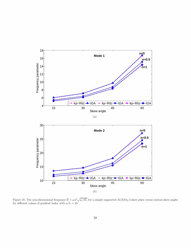
The first two non-dimensionalized frequencies are shown in Figures 18 - (19) for SSSS and CCCC boundary
conditions, respectively. For comparison, the results from the element free kp−Ritz [53] are also plotted. From
the figures, it is seen that the IGA gives higher frequencies than the element free kp−Ritz method. It is also
observed that by increasing the gradient index or decreasing the skew angle, the frequency decreases. In both
cases, the decrease in the natural frequency can be attributed to the stiffness degradation. In the case of gradient
index, the stiffness degradation is due to increased metallic volume fraction, while the geometry of the plate is
a contributing factor in decreasing the frequency when the skew angle decreases. The first eight mode shapes
of fully clamped Al/ZrO2-2 skew plate with skew angle ψ = 45 and gradient index n = 0.5 is plotted in Figure
(20).
Remark 5.1. In the next two sections, the present formulation is extended to study the buckling and flutter
characteristics of the the FGM plates. For the whole, quadratic NUBRS functions with 17 × 17 control points
are used, unless otherwise specified.
5.3. Buckling analysis
In this section, we present the mechanical and thermal buckling behaviour of functionally graded skew plates.
The FGM plate considered here consists of aluminum and alumina (see Table 1 for material properties).
Mechanical Buckling
The critical buckling parameters are defined for uni- and bi- axial compressive loads as:
λcru =N0
xxcrb2
π2Dc
λcrb =N0
yycrb2
π2Dc(43)
37
15 30 45 604
6
8
10
12
14
16
18
Skew angle
Fre
quen
cy p
aram
eter
kp−Ritz IGA kp−Ritz IGA kp−Ritz IGA
Mode 1
n=1
n=0
n=0.5
(a)
15 30 45 6010
15
20
25
30
Skew angle
Fre
quen
cy p
aram
eter
kp−Ritz IGA kp−Ritz IGA kp−Ritz IGA
Mode 2 n=0
n=0.5
n=1
(b)
Figure 18: The non-dimensional frequency ω = ωa2√
ρc/Ec for a simply supported Al/ZrO2-2 skew plate versus various skew anglesfor different values of gradient index with a/h = 10.
38

15 30 45 605
10
15
20
25
30
Skew angle
Fre
quen
cy p
aram
eter
kp−Ritz IGA kp−Ritz IGA kp−Ritz IGA
n=0
n=0.5
n=1
Mode 1
(a)
15 30 45 6015
20
25
30
35
40
Skew angle
Fre
quen
cy p
aram
eter
kp−Ritz IGA kp−Ritz IGA kp−Ritz IGA
Mode 2
n=0
n=0.5
n=1
(b)
Figure 19: The non-dimensional frequency ω = ωa2√
ρc/Ec for a clamped Al/ZrO2-2 skew plate versus various skew angles fordifferent values of gradient index with a/h = 10.
39

0 2 4 6 8 10 12 14 16 18 0
2
4
6
8
−1
−0.5
0
0.5
y−axis
Mode 1
x−axis
z−ax
is
(a) mode 1
0 2 4 6 8 10 12 14 16 18 0
2
4
6
8
−1
−0.5
0
0.5
1
y−axis
Mode 2
x−axis
z−ax
is
(b) mode 2
0 2 4 6 8 10 12 14 16 18 0
2
4
6
8
−1
−0.5
0
0.5
1
y−axis
Mode 3
x−axis
z−ax
is
(c) mode 3
0 2 4 6 8 10 12 14 16 18 0
2
4
6
8
−1
−0.5
0
0.5
1
y−axis
Mode 4
x−axis
z−ax
is
(d) mode 4
0 2 4 6 8 10 12 14 16 18 0
2
4
6
8
−1
−0.5
0
0.5
1
y−axis
Mode 5
x−axis
z−ax
is
(e) mode 5
0 2 4 6 8 10 12 14 16 18 0
2
4
6
8
−1
−0.5
0
0.5
1
y−axis
Mode 6
x−axis
z−ax
is
(f) mode 6
0 2 4 6 8 10 12 14 16 18 0
2
4
6
8
−1
−0.5
0
0.5
1
y−axis
Mode 7
x−axis
z−ax
is
(g) mode 7
0 2 4 6 8 10 12 14 16 18 0
2
4
6
8
−1
−0.5
0
0.5
1
y−axis
Mode 8
x−axis
z−ax
is
(h) mode 8
Figure 20: First eight mode shapes for a clamped Al/Zro2 skew plate with a/h = 10, gradient index n = 0.5 and ψ = 45.
40

where, Dc = Ech3/(12(1 − ν2)). The critical buckling loads evaluated by varying the skew angle of the plate,
volume fraction index and considering mechanical loads such as uni- and biaxial compressive loads are shown
in Tables 7 - 8 for two different thickness ratios. The efficacy of the present formulation is demonstrated by
comparing our results with those in [8]. It can be seen that increasing the gradient index decreases the critical
buckling load. It is also observed that the decrease in the critical value is significant for the material gradient
index n ≤ 2 and that further increase in n yields less reduction in the critical value, irrespective of the skew
angle.
Table 7: Critical buckling parameters for a thin simply supported FGM skew plate with a/h = 100 and a/b = 1.
Skew angle λcr Gradient index, n
0 1 2 5 10
Ref. [8] Present Ref. [8] Present
0λcru 4.0010 3.9998 1.7956 1.8034 1.5320 1.2606 1.0830
λcrb 2.0002 1.9999 0.8980 0.9017 0.7660 0.6303 0.5415
15λcru 4.3946 4.3946 1.9716 1.9716 1.6752 1.3800 1.1868
λcrb 2.1154 2.1154 0.9517 0.9517 0.8086 0.6652 0.5716
30λcru 5.8966 5.8966 2.6496 2.6496 2.2515 1.8607 1.6032
λcrb 2.5365 2.5365 1.1519 1.1519 0.9788 0.8044 0.6905
45λcru 10.1031 10.1031 4.5445 4.5445 3.8625 3.2234 2.7964
λcrb 3.6399 3.6399 1.6863 1.6863 1.4330 1.1774 1.0103
Thermal Buckling
The temperature rise of Tm = 5C in the metal-rich surface of the plate is assumed in the present study. In
addition to nonlinear temperature distribution across the plate thickness, the linear case is also considered in
the present analysis by truncating the higher order terms in Equation (9). The plate is of uniform thickness and
simply supported on all four edges. The critical buckling temperature difference ∆Tcr using two values of the
41

Table 8: Critical buckling parameters for a thick simply supported FGM skew plate with a/h = 10 and a/b = 1.
Skew angle λcr Gradient index, n
0 1 2 5 10
Ref. [8] Present Ref. [8] Present
0λcru 3.7374 3.7307 1.6892 1.6793 1.4198 1.1632 0.9999
λcrb 1.8686 1.8654 0.8449 0.8397 0.7099 0.5816 0.4999
15λcru 4.0791 4.0791 1.8458 1.8458 1.5616 1.2810 1.1021
λcrb 1.9660 1.9660 0.8923 0.8923 0.7550 0.6184 0.5315
30λcru 5.3571 5.3571 2.4298 2.4298 2.0533 1.6886 1.4565
λcrb 2.3226 2.3226 1.0659 1.0659 0.9011 0.7367 0.6326
45λcru 8.5261 8.5261 3.8835 3.8835 3.2679 2.7046 2.3521
λcrb 3.1962 3.1962 1.5030 1.5030 1.2680 1.0335 0.8871
aspect ratio a/b = 1 and 2 with a/h = 10 and for various skew angles is given in Table 9. It can been seen that
the results from the present formulation are in good agreement with the results available in the literature. The
decrease in the critical buckling load with the material gradient index n is attributed to the stiffness degradation
due to the increase in the metallic volume fraction. The thermal stability of the plate increases with the skew
angle of the plate and the same behavior is observed for other values of gradient index n. It can also be seen
that the nonlinear temperature variation through the thickness yields higher critical values compared to the
linear distribution case.
5.4. Flutter analyses
In this section, the present formulation is extended to analyse the flutter characteristics of functionally graded
material plates. Both simply supported and clamped boundary conditions are considered in this study and the
flow direction is assumed to be at right angles to the plate. Only square plate is considered and the results are
presented only for a/h = 100. It should be noted that the present formulation is not limited to this alone. In
42

Table 9: Critical buckling temperature ∆Tcr for a thin simply supported FGM skew plate with a/h = 100 and a/b = 1 under linearand nonlinear temperature rise through the thickness of the plate.
a/b Skew angle Temperature rise Gradient index, n
0
Ref. [55] Present 0.5 1 5
1
0Linear 24.1951 24.1912 9.3787 5.5207 3.8987
Nonlinear 24.1951 24.1912 12.3629 7.6615 4.8740
30Linear 33.9558 33.9503 14.9115 9.7737 7.4681
Nonlinear 33.9558 33.9503 19.6600 13.558 9.3399
60Linear 123.0974 123.1172 65.4519 48.6271 40.0647
Nonlinear 123.0974 123.1172 86.2949 67.4989 50.1064
2
0 Nonlinear 75.4278 75.4475 50.6564 38.6525 28.3067
30 Nonlinear 100.9349 100.9512 69.7225 54.0838 39.9718
60 Nonlinear 304.6912 304.6421 222.0921 177.4280 133.1456
43

all cases, we present the non dimensionalized critical aerodynamic pressure, λcr and critical frequency ωcr as,
unless specified otherwise:
Ωcr = ωcra2
√
ρch
Dc
λcr = λcra3
Dc(44)
where Dc =Ech3
12(1−ν2c )is the bending rigidity of the plate, Ec, νc are the Young’s modulus and Poisson’s ratio of
the ceramic material and ρc is the mass density. In order to be consistent with the existing literature, properties
of the ceramic are used for normalization.
Table 10: Comparison of critical aerodynamic pressure and coalescence frequency for an isotropic plate with various boundaryconditions (a/b = 1, a/h = 100, ν = 0.3, θ′ = 0).
Reference Flutter bounds Boundary condition
1 1 Simply supported Clamped
Ref. [27]λcr 511.11 852.34
ωcr 1840.29 4274.32
Presentλcr 511.92 854.88
ωcr 1844.80 4305.30
Before proceeding with the detailed study, the formulation developed herein is validated against available results
pertaining to the critical aerodynamic pressure and critical frequency for an isotropic plate with and without
a crack. The computed critical aerodynamic pressure and the critical frequency for an isotropic square plate
with various boundary conditions is given in Table 10. Next, the influence of boundary conditions on the flutter
characteristics is studied. For this study, consider a square FGM plate made up of Aluminum-Alumina with
a/h = 100. Figure (21) shows the influence of the boundary conditions on the critical aerodynamic pressure for
various gradient index. It can be seen that the critical pressure is more for the clamped plate in comparison
44

with that of the simply supported plate as expected. It is also seen that the aerodynamic pressure decreases
with increase in the gradient index n. However the rate of decrease is high for low values of n. This can be
attributed to the fact that the stiffness is high for the ceramic plate and minimum for the metallic plate and it
degrades gradually with increase in the gradient index n.
0 1 2 3 4 5 6 7 8 9 10200
300
400
500
600
700
800
900
Gradient index, n
Cri
tica
l aer
od
ynam
ic p
ress
ure
, λcr
SSSSCCCC
Figure 21: Effect of boundary conditions on the critical aerodynamic pressure λcr
6. Conclusions
In this paper, we applied the NURBS based Bubnov-Galerkin iso-geometric finite element method to study the
static and dynamic response of functionally graded material plates. The first order shear deformation plate
theory (FSDT) was used to describe the plate kinematics. Of course the present method is not limited to FSDT
and can easily be extended to higher order plate theories. It is to be noted that with NURBS basis functions,
geometry could be exactly represented. Although in the present study only simple geometries are considered,
the only thing that would change is the information pertaining to the geometry represented by the NURBS
basis functions, when it is applied to model and/or analyze complex geometries. The formulation when applied
45

to thin plates, suffers from shear locking, which is alleviated by employing a modified shear correction factor.
Numerical experiments have been conducted to bring out the influence of the gradient index, the plate aspect
ratio and the plate thickness on the global response of functionally graded material plates. From the detailed
numerical study, it can be concluded that with increasing gradient index n, the static deflection increases, while
the free flexural vibration, critical buckling load and the flutter frequency decreases. This can be attributed to
the reduction in stiffness of the material structure due to increase in the metallic volume fraction.
Acknowledgements
The financial support of European Marie Curie Initial Training Network (FP7-People programme) is gratefully
acknowledged.
Reference
[1] M. Koizumi, The concept of FGM, Ceramic Transactions - Functionally graded materials 34 (1993) 3–10.
[2] J. N. Reddy, Analysis of functionally graded plates, International Journal for Numerical Methods in Engi-
neering 47 (2000) 663–684.
[3] J. Yang, H. S. Shen, Vibration characteristic and transient response of shear-deformable functionally graded
plates in thermal environments, Journal of Sound and Vibration 255 (2002) 579–602.
[4] N. Sundararajan, T. Prakash, M. Ganapathi, Nonlinear free flexural vibrations of functionally graded
rectangular and skew plates under thermal environments, Finite Elements in Analysis and Design 42 (2)
(2005) 152–168.
[5] L. C. Qian, R. C. Batra, L. M. Chen, Static and dynamic deformations of thick functionally graded elastic
plates by using higher order shear and normal deformable plate theory and meshless local Petrov Galerkin
method, Composites Part B: Engineering 35 (2004) 685–697.
46
[6] A. J. M. Ferreira, R. C. Batra, C. M. C. Roque, L. K. Qian, R. M. N. Jorge, Natural frequencies of
functionally graded plates by a meshless method, Composite Structures 75 (2006) 593–600.
[7] S. Natarajan, G. Manickam, Bending and vibration of functionally graded material sandwich plates using
an accurate theory, Finite Elements in Analysis and Design 57 (2012) 32–42.
[8] M. Ganapathi, T. Prakash, N. Sundararajan, Influence of functionally graded material on buckling of skew
plates under mechanical loads, ASCE Journal of Engineering Mechanics 132 (2006) 902–905.
[9] K. J. Bathe, E. Dvorkin, A four node plate bending element based on Mindlin - Reissner plate theory and
mixed interpolation., International Journal for Numerical Methods in Engineering 21 (1985) 367–383.
[10] B. R. Somashekar, G. Prathap, C. R. Babu, A field-consistent four-noded laminated anisotropic plate/shell
element, Computers and Structures 25 (1987) 345–353.
[11] M. Ganapathi, T. K. Varadan, B. S. Sarma, Nonlinear flexural vibrations of laminated orthotropic plates,
Computers and Structures 39 (1991) 685–688.
[12] K. U. Bletzinger, M. Bischoff, E. Ramm, A unified approach for shear-locking free triangular and rectangular
shell finite elements, International Journal for Numerical Methods in Engineering 75 (2000) 321–334.
[13] D. Wang, J. S. Chen, Locking-free stabilized conforming nodal integration for mesh-free Mindlin-Reissner
plate formulation, Computer Methods in Applied Mechanical and Engineering 193 (2004) 1065–1083.
[14] N. T. Nguyen, T. Rabczuk, H. Nguyen-Xuan, S. Bordas, A smoothed finite element method for shell
analysis, Computer Methods in Applied Mechanics and Engineering 198 (2008) 165–177.
[15] H. Nguyen-Xuan, T. Rabczuk, S. Bordas, J. F. Debongnie, A smoothed finite element method for plate
analysis, Computer Methods in Applied Mechanics and Engineering 197 (2008) 1184–1203.
47

[16] W. Kanok-Nukulchai, W. Barry, K. Saran-Yasoontorn, P. H. Bouillard, On elimination of shear locking in
the element-free Galerkin method, International Journal for Numerical Methods in Engineering 52 (2001)
705–725.
[17] X. Q. He, T. Y. Ng, S. Sivashanker, K. M. Liew, Active control of FGM plates with integrated piezoelectric
sensors and actuators, International Journal of Solids and Structures 38 (2001) 1641–1655.
[18] K. M. Liew, K. C. Hung, K. M. Lim, A solution method for analysis of cracked plates under vibration.,
Engineering fracture mechanics 48 (3) (1994) 393–404.
[19] T. Y. Ng, K. Y. Lam, K. M. Liew, Effect of FGM materials on parametric response of plate structures,
Computer Methods in Applied Mechanics and Engineering 190 (2000) 953–962.
[20] J. Yang, H. S. Shen, Dynamic response of initially stressed functionally graded rectangular thin plates,
Composite Structures 54 (2001) 497–508.
[21] H. Matsunaga, Free vibration and stability of functionally graded plates according to a 2D higher-order
deformation theory, Composite Structures 82 (2008) 499–512.
[22] S. S. Vel, R. C. Batra, Exact solutions for thermoelastic deformations of functionally graded thick rectan-
gular plates, AIAA J 40 (2002) 1421–1433.
[23] S. S. Vel, R. C. Batra, Three-dimensional exact solution for the vibration of functionally graded rectangular
plates, Journal of Sound and Vibration 272 (2004) 703–730.
[24] V. Birman, Buckling of functionally graded hybrid composite plates, in: Proceedings of 10th Conference on
Engineering Mechanics, Vol. 2, 1995, pp. 1199–1202.
[25] R. Javaheri, M. Eslami, Buckling of functionally graded plates under in-plane compressive loading, ZAMM
82 (2002) 277–283.
48

[26] J. Woo, S. Meguid, K. Liew, Thermomechanical postbuckling analysis of functionally graded plates and
shallow cylindrical shells, Acta Mech. 165 (2003) 99–115.
[27] T. Prakash, M. Ganapathi, Supersonic flutter characteristics of functionally graded flat panels including
thermal effects, Composite Structures 72 (2006) 10–18.
[28] H. Haddadpour, H. Navazi, F. Shadmehri, Nonlinear oscillations of a fluttering functionally graded plate,
Composite Structures 79 (2007) 242–250.
[29] K.-J. Sohn, J.-H. Kim, Structural stability of functionally graded panels subjected to aero-thermal loads,
Composite Structures 82 (2008) 317–325.
[30] K.-J. Sohn, J. Kim, Nonlinear thermal flutter of functionally graded panels under a supersonic flow, Com-
posite Structures 88 (2009) 380–387.
[31] J. Yang, Y. Hao, W. Zhang, S. Kitipornchai, Nonlinear dynamic response of a functionally graded plate
with a through-width surface crack, Nonlinear Dynamics 59 (2010) 207–219.
[32] S. Kitipornchai, L. Ke, J. Y. andY Xiang, Nonlinear vibration of edge cracked functionally graded Timo-
shenko beams, Journal of Sound and Vibration 324 (2009) 962–982.
[33] S. Natarajan, P. Baiz, M. Ganapathi, P. Kerfriden, S. Bordas, Linear free flexural vibration of cracked
functionally graded plates in thermal environment, Computers and Structures 89 (2011) 1535–1546.
[34] S. Natarajan, P. Baiz, S. Bordas, P. Kerfriden, T. Rabczuk, Natural frequencies of cracked functionally
graded material plates by the extended finite element method, Composite Structures 93 (2011) 3082–3092.
[35] P. M. Baiz, S. Natarajan, S. Bordas, P. Kerfriden, T. Rabczuk, Linear buckling analysis of cracked plates
by SFEM and XFEM, Journal of Mechanics of Materials and Structure 6 (2011) 1213–1238.
49

[36] L. B. a. da Veiga, A. Buffa, C. Lovadina, M. Martinelli, G. Sangalli, An iso-geometric method for the
reissner-mindlin plate bending problem, Computer Methods in Applied Mechanics and Engineering 209–
212 (2012) 45–53.
[37] W. Kanok-Nukulchai, W. Barry, K. Saran-Yasontorn, P. Bouillard, On elimination of shear locking in
the element-free galerkin method, International Journal for Numerical Methods in Engineering 52 (2001)
705–725.
[38] F. Kikuchi, K. Ishii, An improved 4-node quadrilateral plate bending element of the reissne-mindlin type,
Computational Mechanics 23 (1999) 240–249.
[39] L. Wu, Thermal buckling of a simply supported moderately thick rectangular FGM plate, Composite
Structures 64 (2004) 211–218.
[40] S. Rajasekaran, D. Murray, Incremental finite element matrices, ASCE Journal of Structural Divison 99
(1973) 2423–2438.
[41] V. Birman, L. Librescu, Supersonic flutter of shear deformation laminated flat panel, Journal of Sound and
Vibration 139 (1990) 265–275.
[42] M. Ganapathi, M. Touratier, Supersonic flutter analysis of thermally stressed laminated composite flat
panels, Composite Structures 34 (1996) 241–248.
[43] J. A. Cottrell, T. J. Hughes, Y. Bazilevs, Isogeometric analysis: Toward integration of CAD and FEA,
John Wiley, 2009.
[44] V. P. Nguyen, R. N. Simpson, S. P. Bordas, T. Rabczuk, An introduction to Isogeometric analysis with
MATLAB implementation: FEM and XFEM formulations, in review.
[45] M. Singha, T. Prakash, M. Ganapathi, Finite element analysis of functionally graded plates under transverse
load, Finite elements in Analysis and Design 47 (2011) 453–460.
50

[46] D. Gilhooley, R. Batra, J. Xiao, M. McCarthy, J. Gillespie, Analysis of thick functionally graded plates
by using higher order shear and normal deformable plate theory and MLPG method with radial basis
functions, Composite Structures 80 (2007) 539–552.
[47] Y. Lee, X. Zhao, K. Liew, Thermo-elastic analysis of functionally graded plates using the element free
kp−Ritz method, Smart Materials and Structures 18 (2009) 035007.
[48] H. Nguyen-Xuan, L. V. Tran, H. Thai, T. Nguyen-Thoi, Analysis of functionally graded plates by an
efficient finite element method with node-based strain smoothing, Thin Walled Structures 54 (2012) 1–18.
[49] C. Thai, H. Nguyen-Xuan, N. Nguyen-Thanh, T.-H. Le, T. Nguyen-Thoi, T. Rabczuk, Static, free vibration
and buckling analysis of laminated composite Reissner-Mindlin plates using NURBS based isogeometric
approach, International Journal for Numerical Methods in Engineering 91 (2012) 571–603.
[50] L. Croce, P. Venini, Finite elements for functionally graded Reissner-Mindlin plates, Computer Methods in
Applied Mechanics and Engineering 193 (2007) 705–725.
[51] X. Zhao, K. Liew, Geometrically nonlinear analysis of functionally graded plates using the element free
kp−Ritz method, Computer Methods in Applied Mechanics and Engineering 198 (2009) 2796–2811.
[52] H. Nguyen-Xuan, L. V. Tran, T. Nguyen-Thoi, H. Vu-Do, Analysis of functionally graded plates using an
edge-based smoothed finite element method, Composite Structures 93 (2011) 3019–3039.
[53] X. Zhao, Y. Lee, K. Liew, Free vibration analysis of functionally graded plates using the element free
kp−Ritz method, Journal of Sound and Vibration 319 (2009) 918–939.
[54] S. H. Hashemi, M. Fadaee, S. Atashipour, A new exact analytical approach for free vibration of reissne-
mindlin functionally graded rectangular plates, International Journal of Mechanical Sciences 53 (2011)
11–22.
51

[55] M. Ganapathi, T. Prakash, Thermal buckling of simply supported functionally graded skew plates, Com-
posite Structures 74 (2006) 247–250.
52