preparation of functionally graded mullite-zirconia ... · preparation of functionally graded...
TRANSCRIPT
Preparation of functionally graded mullite-zirconia composite usingelectrophoretic deposition (EPD)
HENK S. C. METSELAAR
AHMED S. MAHDIUniversity of Malaya
Center of Research Advanced MaterialsUniversity of Malaya
Lembah Pantai, 50603 Kuala LumpurMALAYSIA
ZAID A. SABRE
Abstract: The mechanical properties such as hardness and especially fracture toughness of present structural ce-ramics are not enough to permit design of high performance products. It is generally believed that further im-provement of fracture toughness and hardness is only possible by making composites of ceramics with ceramicfiber. The wide-spread use of mullite–zirconia (MZ) composites is due to the fact that the zirconia dispersion inthe mullite matrix improves the thermo-mechanical properties. The preparation process to produce the compos-ite sample using electrophoretic deposition (EPD) which deals with three types of powder: α-alumina, silica andzirconia, mixed with the suspension based on 2-butanone, n-butylamine and polyvinyl butyral (PVB). Hardnessand fracture toughness were measured using indentation methods on cross sections of the sample with applyingtwo loads: 5kg and 10kg. Electron microscopy analysis (SEM) and X-ray diffraction (XRD) tests were used toexamine the microstructure, composition and crystallization behavior of the deposits. The results were comparedwith mullite matrix properties to detect the enhancement in mechanical properties.
Key–Words: Electrophoretic deposition, ceramic matrix comppsites, mullite, zirconia, functionally graded mate-rial, mechanical properties
1 IntroductionDuring the last 25 years, tremendous progress hasbeen made in the development and advancement ofCMCs (ceramic matrix composites) under various re-search programs. CMCs find applications in advancedaerojet engines, stationary gas turbines for electricalpower generation, heat exchangers, hot gas filters, ra-diant burners, heat treatment and materials growth fur-naces, nuclear fusion reactors, automobiles, biologi-cal implants [1]. Mullite is one of the basic ceramicmaterials traditionally used for refractories and is con-sidered an attractive selection for many industrial ap-plications because of its high temperature mechani-cal properties. For the development of the structuralmaterials, mullite has been delayed since it has a lowfracture toughness and relatively low strength at roomtemperature compared with other engineering ceram-ics.
The extensive use of mullite/zirconia compositesis due to the fact that the zirconia dispersion in themullite matrix improves the thermo-mechanical prop-erties, leading to toughness by transformation andmicrocracking[2].
Mullite/zirconia composites can be prepared us-
ing various methods: (1) Sintering of mullite powderand zirconia powder (2) Reaction sintering of aluminaand zircon powders (3) Reaction sintering of alumina,silica and zirconia powders [2–3].
It has been reported that the optimum content ofzirconia is ≈ 15wt%[4].
In this research the third method was used and thefracture toughness and hardness are improved whenzirconia reinforced mullite matrix using EPD tech-nique to fabricate the composite sample.
2 Experimental
2.1 Materials
Commercially available (SiO2 , 99.9% purity, AldrichChemical Company Inc., USA) and α-Al2O3 (99.95%purity, Alfa Aesar Chemical Company Inc, USA) pow-ders were used as the starting materials representingthe composition of mullite (3Al2O3.2SiO2) and ZrO2(99.5% purity, Aldrich chemical company Inc, USA).2-butanone (96% purity-Ajax), n-butylamine and PVBform the suspension medium.
Recent Advances in Mathematical Methods, Intelligent Systems and Materials
ISBN: 978-1-61804-168-5 96
2.2 Suspension preparationA total of 50g of mullite (α-Al2O3/SiO2) with 60wt%for α-Al2O3, 40wt% for SiO2 and 10g ZrO2 wereprepared for the sample. These three powders wereseparately milled for 24h in a planetary ball mill at200 rpm using zirconia balls with 10mm diameter asmilling media with a ball to powder ratio of 5:1. Sub-sequently, the powders were milled horizontally inethanol for 24h using the same balls to break up hardagglomerates. The ethanol was evaporated in an ovenat 90 ◦C for 48h, then the powders were placed in adrying cabinet at 25 ◦C.
The present study used non-aqueous EPD whichuses organic solvents which normally are less polarthan water. A basic requirement for EPD is that sus-pended particles must have a high electrophoretic mo-bility that can be increased by adding dispersants, son-butylamine was used as dispersant in this suspen-sion, and polyvinylbutyral (PVB) as a binder. Thesuspension system used technical grade 2-butanone,n-butylamine and PVB as suspension medium. n-butylamine was used to disperse the metal oxide pow-ders in 2-butanone and PVB.
The mixing proportion is 10g of powder per100mL in the ratio of 60wt% for α-Al2O3 and40wt% for SiO2. All weight percentages of additivesare taken from total powder weight. 2wt% of PVB wasadded as well as 10vol% of n-butylamine. PVB wasfirst dissolved in 40mL of 2-butanone and then addedto the main suspension.
Three suspensions were prepared and mixed withthe powders that were prepared previously in a glasscontainer by a magnetic stirrer for 24 hour, andthen the pH value was measured by a pH meter foreach suspension. The suspensions were then put inglass containers and placed in an ultrasonic cleaningbath with a frequency of about 15kHz to 45kHz for30min. Table 1 indicates the suspension composi-tions.
2.3 Electrophoretic deposition and sinteringEPD is one of the colloidal processes that is used inceramic production with many advantages: short for-mation time, simple equipment and the process can beapplied to any shape depending on the electrode shape
Table 1: Compositions for 200mL suspension
suspensionMullite (g)
ZrO2 2-butanone (mL) n-butylamine (mL) PVB (g) pH at 25 ◦Cα-Al2O3 SiO2
I 12 8 0 180 20 0.4 12.6II 6 4 10 180 20 0.4 12.36III 12 8 0 180 20 0.4 12.29
such as cylinder, spherical and flat plates.The parameters affecting EPD, can be classified in
two types, firstly those related to the suspension prop-erties such as electrical conductivity, pH, particle sizeand size distribution, binder and dispersant concentra-tion and ζ -potential, and secondly the parameters thatrelate to the EPD process, such as deposition time, theapplied voltage, size and shape of the electrode andthe distance between the electrodes.
The EPD cell in this study was described in [5]and consisted of two stainless steel electrodes with asurface area of 10cm2 (5.25cm × 1.923cm) and athickness of 0.5cm. The surfaces of the depositionelectrodes were polished to facilitate the removal ofthe deposit and to avoid cracking of the deposit duringdrying. Furthermore, the edges of the deposition elec-trode were enclosed by tape in order to avoid deposi-tion around the edges of the electrode. The electrodeswere cleaned with acetone then vertically placed in apolytetrafluoroethylene (PTFE) vessel. PTFE was usedin order to avoid deposition between suspension andvessel as PTFE is a non-conductive polymer. The PTFEcontainer had a volume of 100mL. The distance be-tween the electrodes was fixed at 3cm.
A DC voltage source, Apparatus Corporation, wasused to apply the electric field. The source was capa-ble of performing either as a constant current or asa constant voltage source. A voltage of 275V wasapplied for 30min. The suspensions were pumpedthrough the deposition cell by peristaltic pumps. Peri-staltic tubing with a diameter of 4mm was used for thecirculation system. The maximum and minimum feedrates were 4.25mLs−1 and 0.12mLs−1, respectively.
The total deposition time for composite materialwas 30min. A magnetic stirrer was used to mix thesuspension during all EPD steps. Initially suspen-sion I, loaded with 100gL−1 mullite (silica and alu-mina), was poured in the deposition cell and circulat-ing process continued between the deposition cell andthe circulating beaker using pump 1 for 600s, and thensuspension II with 50gL−1 mullite and 50gL−1 ZrO2was added into the beaker of circulating suspensionusing pump 2 and was pumped through the depositioncell by means of pump 1 at a rate of 2.5mLs−1. Thepump rate between deposition cell and circulating sus-pension was fixed throughout the deposition process.
Recent Advances in Mathematical Methods, Intelligent Systems and Materials
ISBN: 978-1-61804-168-5 97
After 1200s of deposition, suspension III, with100gL−1 mullite was added to the circulating suspen-sion by pump 2 at a rate of 0.4mLs−1. After 300s ofdeposition, the addition of the suspension was com-pleted. During the subsequent step, the suspensionwas circulated for 300s without any future additions,and during all the described steps, EPD was continuedin the deposition cell. The powder deposits took placeon the anode electrode due to the negative charge ofthe particles.
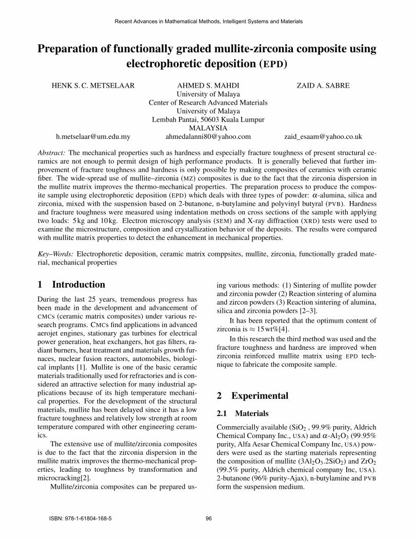
After EPD, the green bodies were dried in air for48h. Afterwards, the powder deposits were removedfrom the electrode. The green bodies were dried in anoven at 100 ◦C for 12h in order to avoid cracking andpreparation for sintering. The two main factors affect-ing sintering are sintering temperature and time. Pureoxide ceramics require relatively long time and hightemperature because the diffusion proceeds in solidstate. The green bodies obtained by the EPD weresintered in a chamber furnace, after the sample haddried; the sintering process took place at 1500 ◦C for2h. Fig. 1 shows the sample after EPD.
Figure 1: The sample after EPD
To provide time for the binder to burn out, thesample was heated at 3 ◦Cmin−1 to 500 ◦C, held at500 ◦C for 30min and then heated to the final sinteringtemperature at a rate of 5 ◦Cmin−1 and held at 1500 ◦Cfor 2h and furnace cooled. To avoid and minimize thedamage to the samples during sintering, the sampleswere placed on an alumina crucible. Length and widthof sample were measured before and after sintering todetermine linear shrinkage.
2.4 Preparation of samplesThe sintered samples were cross-sectioned on a dia-mond cutter using sufficient flow of non-oily coolant.The surfaces of the sintered samples were ground withemery paper of 400, 600, 800, 1200 and 1500 gritand polished to a near mirror finish. The ground sam-ples were polished with cotton to reduce scratches onthe surface, and to make a mirror surface finish withminimum scratches. After grinding and polishing, thesamples were thermally etched at 1350 ◦C for 30min.
Finally, the samples were moulded in epoxy toallow easier handling during the hardness tests.
2.5 hardness and toughness test
The Vickers hardness was determined on a Mitutoyo,AVK-C2. The test force is maintained for 15s and 5kgand 10kg loads were applied by the indenter to thesample’s cross-sectioned surface to obtain a hardnessprofile.
The indentation fracture toughness, KIc was cal-culated from the length of the cracks induced by thesame indent using the Anstis formula, as shown ineq. 1[6].
KIc = η
√EH
F
C32
(1)
Where η is a geometric factor, estimated at 0.016, Ethe Young’s modulus, H is the hardness, F is the in-dentation load, and C is the indentation radial crackhalf length of the cracks parallel to the layers at thesurface. Since the E value for the composite is not
known η
√EH is estimated to be 0.062 which is a suit-
able value for mullite ceramics.
3 Results and Discussion3.1 Density and porosityThe sample deposit was smooth and an approximatelyflat surface was obtained. Exactly how roughnessis affected by the suspension stability is unclear butone can assume that the convective motion, powderamounts and applied voltage play important roles.The dimension of the green deposit and shrinkage ofthe deposit with dimensions after sintering are shownin Table 2.
It is observed that the shrinkage perpendicular tothe deposition surface is significantly higher than par-allel to the deposition surface.
Density measurements were taken according tothe Archimedes method. The result is shown in Ta-ble 3. The porosity may be caused by exaggeratedgrain growth.
Recent Advances in Mathematical Methods, Intelligent Systems and Materials
ISBN: 978-1-61804-168-5 98
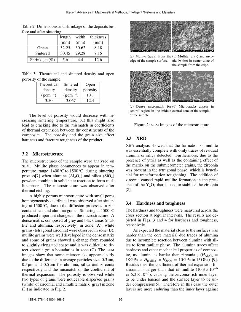
Table 2: Dimensions and shrinkage of the deposits be-fore and after sintering
length width thickness(mm) (mm) (mm)
Green 32.25 30.62 8.18Sintered 30.45 29.28 7.15
Shrinkage (%) 5.6 4.4 12.6
Table 3: Theoretical and sintered density and openporosity of the sample.
Theoretical Sintered Opendensity density porosity
(gcm−3) (gcm−3) (%)3.50 3.067 12.4
The level of porosity would decrease with in-creasing sintering temperature, but this might alsolead to cracking due to the mismatch in coefficientsof thermal expansion between the constituents of thecomposite. The porosity and the grain size affecthardness and fracture toughness of the product.
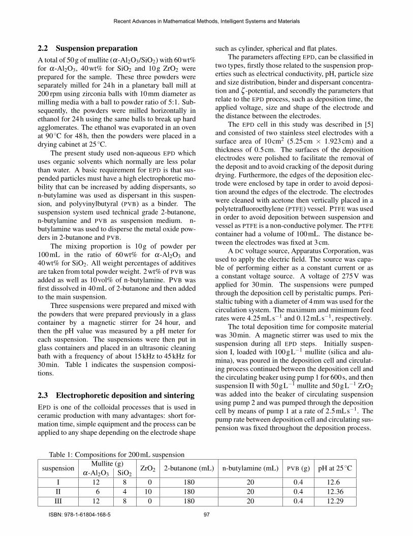
3.2 MicrostructureThe microstructures of the sample were analysed onSEM. Mullite phase commences to appear in tem-perature range 1400 ◦C to 1500 ◦C during sinteringprocess[7] when alumina (Al2O3) and silica (SiO2)powders combine in solid state reaction to form mul-lite phase. The microstructure was observed afterthermal etching.
A highly porous microstructure with small poreshomogeneously distributed was observed after sinter-ing at 1500 ◦C, due to the diffusion processes in zir-conia, silica, and alumina grains. Sintering at 1500 ◦Cproduced important changes in the microstructure. Adense matrix composed of grey and black areas (mul-lite and alumina, respectively) in zone (A), whitegrains (tetragonal zirconia) were observed in zone (B),mullite grains were well developed in the dense matrixand some of grains showed a change from roundedto slightly elongated shape and it was difficult to de-tect zirconia grain boundaries in zone (C). The SEMimages show that some microcracks appear clearlydue to the difference in average particles size, 0.3µm,0.5µm and 0.5µm for alumina, silica and zirconiarespectively and the mismatch of the coefficient ofthermal expansion. The porosity is observed whiletwo types of grains were noticeable dispersed grains(white) of zirconia, and a mullite matrix (gray) in zone(D) as indicated in Fig. 2.
(a) Mullite (gray) from theedge of the sample surface.
(b) Mullite (gray) and zirco-nia (white) in center zone ofthe sample from the edge.
(c) Dense micrograph forcentral region in the middleof the sample
(d) Microcracks appear incentral zone of the sample
Figure 2: SEM images of the microstructure
3.3 XRDXRD analysis showed that the formation of mullitewas essentially complete with omly traces of residualalumina or silica detected. Furthermore, due to thepresence of yttria as well as the containing effect ofthe matrix on the submicrometer grains, the zirconiawas present in the tetragonal phase, which is benefi-cial for transformation toughening. The addition ofzirconia caused rapid mullite formation in the pres-ence of the Y2O3 that is used to stabilise the zirconia[8].
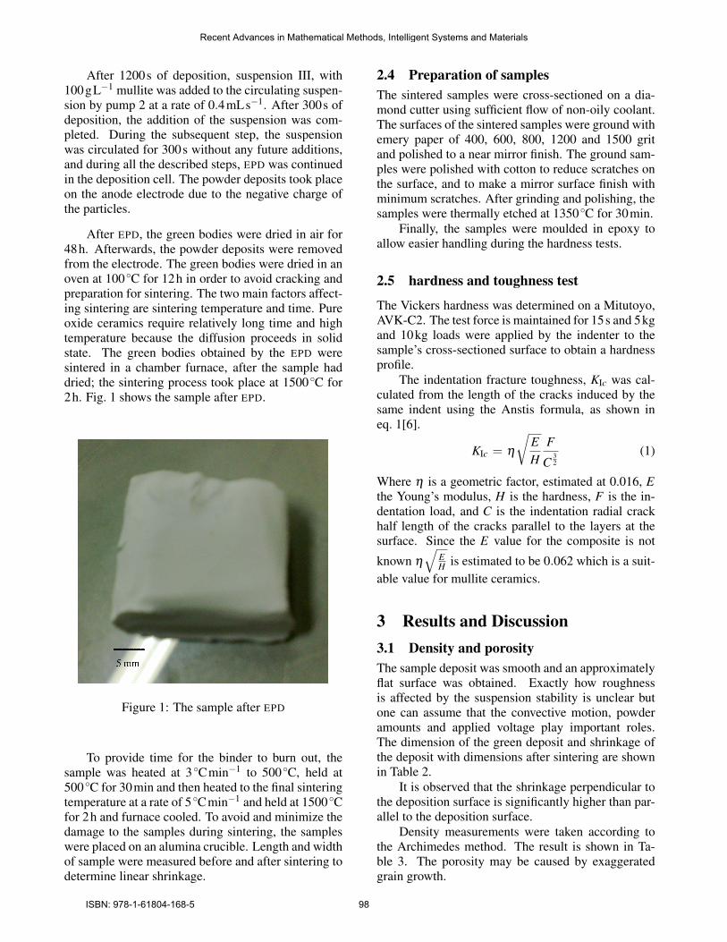
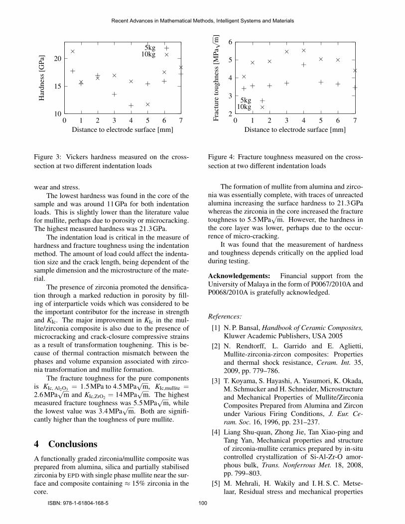
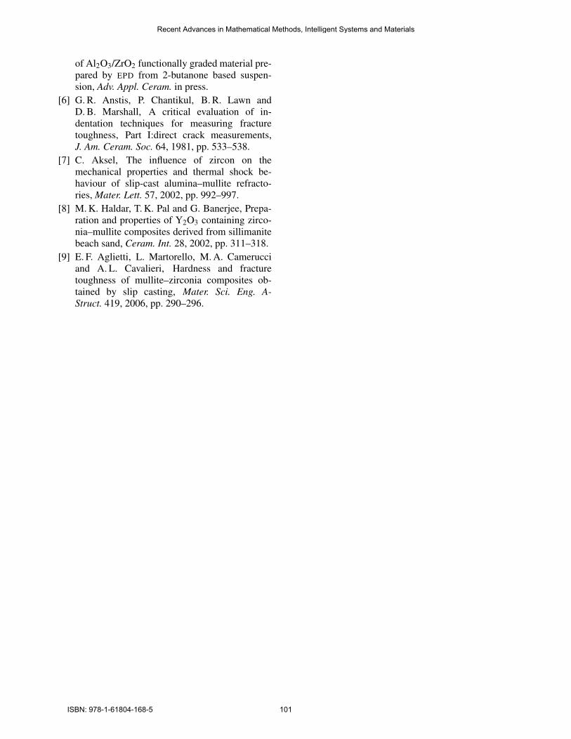
3.4 Hardness and toughnessThe hardness and toughness were measured across thecross section at regular intervals. The results are de-picted in Figs. 3 and 4 for hardness and toughness,respecively.
As expected the material close to the surfaces washarder than the core material due traces of aluminadue to incomplete reaction between alumina with sil-ica to form mullite phase. The alumina traces affecthardness and other mechanical properties of compos-ite, as alumina is harder than zirconia , (HAl2O3 =18GPa > Hmullite ≈ HZrO2 = 10GPa to 15GPa) [9].Besides this, the coefficient of thermal expansion forzirconia is larger than that of mullite (10.3×10⁻⁶
vs 5.3×10⁻⁶), causing the zirconia-rich inner layerto be under tension and the surface layer to be un-der compression[5]. Therefore in this case the outerlayers are more enduring than the inner layer against
Recent Advances in Mathematical Methods, Intelligent Systems and Materials
ISBN: 978-1-61804-168-5 99
10
15
20
0 1 2 3 4 5 6 7
Har
dnes
s[G
Pa]
Distance to electrode surface [mm]
5kg
+
++
+
+
+ ++
+10kg×
× × ××
×
× ×
×
Figure 3: Vickers hardness measured on the cross-section at two different indentation loads
wear and stress.The lowest hardness was found in the core of the
sample and was around 11GPa for both indentationloads. This is slightly lower than the literature valuefor mullite, perhaps due to porosity or microcracking.The highest measured hardness was 21.3GPa.
The indentation load is critical in the measure ofhardness and fracture toughness using the indentationmethod. The amount of load could affect the indenta-tion size and the crack length, being dependent of thesample dimension and the microstructure of the mate-rial.
The presence of zirconia promoted the densifica-tion through a marked reduction in porosity by fill-ing of interparticle voids which was considered to bethe important contributor for the increase in strengthand KIc. The major improvement in KIc in the mul-lite/zirconia composite is also due to the presence ofmicrocracking and crack-closure compressive strainsas a result of transformation toughening. This is be-cause of thermal contraction mismatch between thephases and volume expansion associated with zirco-nia transformation and mullite formation.
The fracture toughness for the pure componentsis KIc, Al2O3 = 1.5MPa to 4.5MPa
√m, KIc,mullite =
2.6MPa√
m and KIc,ZrO2 = 14MPa√
m. The highestmeasured fracture toughness was 5.5MPa
√m, while
the lowest value was 3.4MPa√
m. Both are signifi-cantly higher than the toughness of pure mullite.
4 ConclusionsA functionally graded zirconia/mullite composite wasprepared from alumina, silica and partially stabilisedzirconia by EPD with single phase mullite near the sur-face and composite containing ≈ 15% zirconia in thecore.
2
3
4
5
6
0 1 2 3 4 5 6 7Frac
ture
toug
hnes
s[M
Pa√
m]
Distance to electrode surface [mm]
5kg
+ + + +
+
+ + +
+10kg
×
× ×× ×
× ××
×
Figure 4: Fracture toughness measured on the cross-section at two different indentation loads
The formation of mullite from alumina and zirco-nia was essentially complete, with traces of unreactedalumina increasing the surface hardness to 21.3GPawhereas the zirconia in the core increased the fracturetoughness to 5.5MPa
√m. However, the hardness in
the core layer was lower, perhaps due to the occur-rence of micro-cracking.
It was found that the measurement of hardnessand toughness depends critically on the applied loadduring testing.
Acknowledgements: Financial support from theUniversity of Malaya in the form of P0067/2010A andP0068/2010A is gratefully acknowledged.
References:
[1] N. P. Bansal, Handbook of Ceramic Composites,Kluwer Academic Publishers, USA 2005
[2] N. Rendtorff, L. Garrido and E. Aglietti,Mullite-zirconia-zircon composites: Propertiesand thermal shock resistance, Ceram. Int. 35,2009, pp. 779–786.
[3] T. Koyama, S. Hayashi, A. Yasumori, K. Okada,M. Schmucker and H. Schneider, Microstructureand Mechanical Properties of Mullite/ZirconiaComposites Prepared from Alumina and Zirconunder Various Firing Conditions, J. Eur. Ce-ram. Soc. 16, 1996, pp. 231–237.
[4] Liang Shu-quan, Zhong Jie, Tan Xiao-ping andTang Yan, Mechanical properties and structureof zirconia-mullite ceramics prepared by in-situcontrolled crystallization of Si-Al-Zr-O amor-phous bulk, Trans. Nonferrous Met. 18, 2008,pp. 799–803.
[5] M. Mehrali, H. Wakily and I. H. S. C. Metse-laar, Residual stress and mechanical properties
Recent Advances in Mathematical Methods, Intelligent Systems and Materials
ISBN: 978-1-61804-168-5 100
of Al2O3/ZrO2 functionally graded material pre-pared by EPD from 2-butanone based suspen-sion, Adv. Appl. Ceram. in press.
[6] G. R. Anstis, P. Chantikul, B. R. Lawn andD. B. Marshall, A critical evaluation of in-dentation techniques for measuring fracturetoughness, Part I:direct crack measurements,J. Am. Ceram. Soc. 64, 1981, pp. 533–538.
[7] C. Aksel, The influence of zircon on themechanical properties and thermal shock be-haviour of slip-cast alumina–mullite refracto-ries, Mater. Lett. 57, 2002, pp. 992–997.
[8] M. K. Haldar, T. K. Pal and G. Banerjee, Prepa-ration and properties of Y2O3 containing zirco-nia–mullite composites derived from sillimanitebeach sand, Ceram. Int. 28, 2002, pp. 311–318.
[9] E. F. Aglietti, L. Martorello, M. A. Camerucciand A. L. Cavalieri, Hardness and fracturetoughness of mullite–zirconia composites ob-tained by slip casting, Mater. Sci. Eng. A-Struct. 419, 2006, pp. 290–296.
Recent Advances in Mathematical Methods, Intelligent Systems and Materials
ISBN: 978-1-61804-168-5 101