numerical simulation of hydro-mechanical deep drawing - a...
TRANSCRIPT
Numerical Simulation of Hydro-mechanical Deep Drawing - A Study on the Effect of Process Parameters on Drawability
and Thickness Variation
Swadesh Kumar Singh and D. Ravi Kumar*
Department of Mechanical Engineering Indian Institute of Technology Delhi, New Delhi 110 016, India
* Corresponding Author (Email: [email protected])
Abstract. Hydro-mechanical deep drawing is a process for producing cup shaped parts with the assistance of a pressurized fluid. In the present work, numerical simulation of the conventional and counter pressure deep drawing processes has been done with the help of a finite element method based software. Simulation results were analyzed to study the improvement in drawability by using hydro-mechanical processes. The thickness variations in the drawn cups were analyzed and also the effect of counter pressure and oil gap on the thickness distribution was studied. Numerical simulations were also used for the die design, which combines both drawing and ironing processes in a single operation. This modification in the die provides high drawability, facilitates smooth material flow, gives more uniform thickness distribution and corrects the shape distortion.
INTRODUCTION
Deep drawing is an important sheet metal forming process in which thin sheets are formed into cup shaped components by causing large plastic deformation in the flange and the cup wall. The importance of deep drawing processes with the assistance of fluid pressure has increased significantly in the recent years due to certain advantages of these processes over conventional drawing like better formability, improved surface finish etc. One such process is hydro-mechanical deep drawing, in which parts are drawn from sheet metal blanks using counter pressure of a fluid. Hydro-mechanical deep drawing offers several advantages over conventional deep drawing e.g. increased limiting draw ratio (drawability), better surface finish (because flange suffers less damage), more uniform thickness distribution in the drawn cups etc. [1-4]. Apart from the conventional variables which influence the deep drawing process, additional process parameters like oil gap, pre-bulging pressure (initial pressure in the chamber) and instantaneous pressure in the chamber are important in hydro-mechanical deep drawing. Therefore study of the influence of these parameters on drawability
and thickness variation in hydro-mechanical deep drawing through experimental and numerical techniques is an important area of research.
Finite Element Simulation
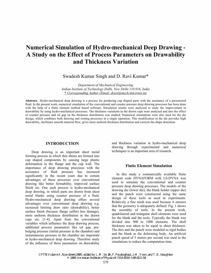
In this study a commercially available finite element code DYNAFORM with LS-DYNA was used to simulate the conventional and counter pressure deep drawing processes. The models of the drawing die (lower die), the blank holder (upper die) and the punch were constructed using the same design of these tools as used in experiments. Relatively a fine mesh was used because it ensures that the geometry is adequately defined. Fig. 1 shows the assembly of tools. In the present work, quadrilateral and triangular shell elements were used for the blank and the tools. Typically the blank was divided into 900 to 1000 elements. The shell thickness was taken to be equal to sheet thickness. The dies and the punch were modeled as rigid bodies and the blank as the deforming body. An artificial punch speed of 5 meters per second was used in the simulations to reduce the computation time.
579
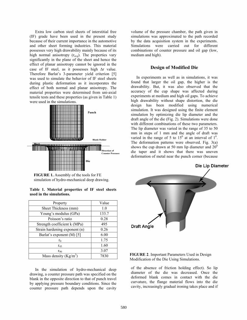
FIGURE 1. Assembly of the tools for FE simulation of hydro-mechanical deep drawing.
FIGURE 2. Important Parameters Used in Design Modification of the Die Using Simulations.
Extra low carbon steel sheets of interstitial free (IF) grade have been used in the present study because of their current importance in the automotive and other sheet forming industries. This material possesses very high drawability mainly because of its high normal anisotropy (ravg). The properties vary significantly in the plane of the sheet and hence the effect of planar anisotropy cannot be ignored in the case of IF steel, as it possesses high ∆r value. Therefore Barlat’s 3-parameter yield criterion [5] was used to simulate the behavior of IF steel sheets during plastic deformation as it incorporates the effect of both normal and planar anisotropy. The material properties were determined from uni-axial tensile tests and these properties (as given in Table 1) were used in the simulations.
Table 1. Material properties of IF steel sheets used in the simulations.
Property Value Sheet Thickness (mm) 1.0
Young’s modulus (GPa) 133.7 Poisson’s ratio 0.28
Strength coefficient k (MPa) 495 Strain hardening exponent (n) 0.26
Barlat’s exponent (M) [5] 6.00 r0 1.75 r45 1.60 r90 3.07
Mass density (Kg/m3) 7830
In the simulation of hydro-mechanical deep drawing, a counter pressure path was specified on the blank in the opposite direction to that of punch travel by applying pressure boundary conditions. Since the counter pressure path depends upon the cavity
volume of the pressure chamber, the path given in simulations was approximated to the path recorded by the data acquisition system in the experiments. Simulations were carried out for different combinations of counter pressure and oil gap (low, medium and high).
Design of Modified Die
In experiments as well as in simulations, it was found that larger the oil gap, the higher is the drawability. But, it was also observed that the accuracy of the cup shape was affected during experiments at medium and high oil gaps. To achieve high drawability without shape distortion, the die design has been modified using numerical simulation. It was designed using the finite element simulation by optimizing die lip diameter and the draft angle of the die (Fig. 2). Simulations were done with different combinations of these two parameters. The lip diameter was varied in the range of 35 to 50 mm in steps of 1 mm and the angle of draft was varied in the range of 5 to 150 at an interval of 10. The deformation patterns were observed. Fig. 3(a) shows the cup drawn at 50 mm lip diameter and 200 die taper and it shows that there was uneven deformation of metal near the punch corner (because
of the absence of friction holding effect). So lip diameter of the die was decreased. Once the deformed blank comes in contact with the die curvature, the flange material flows into the die cavity, increasingly gradual ironing takes place and if
580
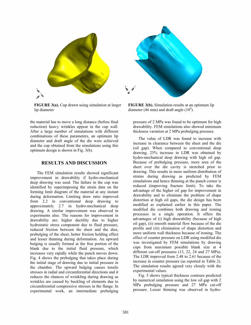
FIGURE 3(a). Cup drawn using simulation at larger lip diameter
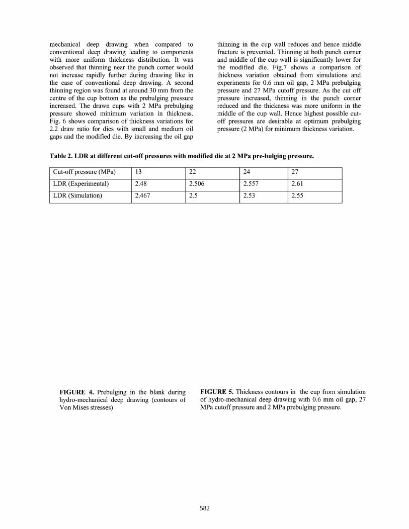
FIGURE 3(b). Simulation results at an optimum lip diameter (46 mm) and draft angle (100).
the material has to move a long distance (before final reduction) heavy wrinkles appear in the cup wall. After a large number of simulations with different combinations of these parameters, an optimum lip diameter and draft angle of the die were achieved and the cup obtained from the simulations using this optimum design is shown in Fig. 3(b).
RESULTS AND DISCUSSION
The FEM simulation results showed significant improvement in drawability if hydro-mechanical deep drawing was used. The failure in the cup was identified by superimposing the strain data on the forming limit diagram of the material at any instant during deformation. Limiting draw ratio improved from 2.2 in conventional deep drawing to approximately 2.7 in hydro-mechanical deep drawing. A similar improvement was observed in experiments also. The reasons for improvement in drawability are: higher ductility due to higher hydrostatic stress component due to fluid pressure, reduced friction between the sheet and the dies, prebulging of the sheet, better friction holding effect and lesser thinning during deformation. An upward bulging is usually formed at the free portion of the blank due to the initial fluid pressure, which increases very rapidly while the punch moves down. Fig. 4 shows the prebulging that takes place during the initial stage of drawing due to initial pressure in the chamber. The upward bulging causes tensile stresses in radial and circumferential directions and it reduces the chances of wrinkling during drawing as wrinkles are caused by buckling of elements due to circumferential compressive stresses in the flange. In experimental work, an intermediate prebulging
pressure of 2 MPa was found to be optimum for high drawability. FEM simulations also showed minimum thickness variation at 2 MPa prebulging pressure.
The value of LDR was found to increase with increase in clearance between the sheet and the die (oil gap). When compared to conventional deep drawing, 25% increase in LDR was obtained by hydro-mechanical deep drawing with high oil gap. Because of prebulging pressure, more area of the sheet over the die cavity is stretched prior to drawing. This results in more uniform distribution of strains during drawing as predicted by FEM simulations and hence thinning at the punch corner is reduced (improving fracture limit). To take the advantage of the higher oil gap for improvement in drawability and to eliminate the problem of shape distortion at high oil gaps, the die design has been modified as explained earlier in this paper. The modified die combines both drawing and ironing processes in a single operation. It offers the advantages of (i) high drawability (because of high oil gap), (ii) smooth material flow because of the die profile and (iii) elimination of shape distortion and more uniform wall thickness because of ironing. The effect of counter pressure on LDR using modified die was investigated by FEM simulations by drawing cups from maximum possible blank size at 4 different cut-off pressures (13, 22, 24 and 27 MPa). The LDR improved from 2.48 to 2.61 because of the increase in counter pressure (as reported in Table 2). The simulation results agreed very closely with the experimental values.
Fig. 5 shows typical thickness contours predicted by numerical simulation using the low oil gap with 2 MPa prebulging pressure and 27 MPa cut-off pressure. Lesser thinning was observed in hydro-
581
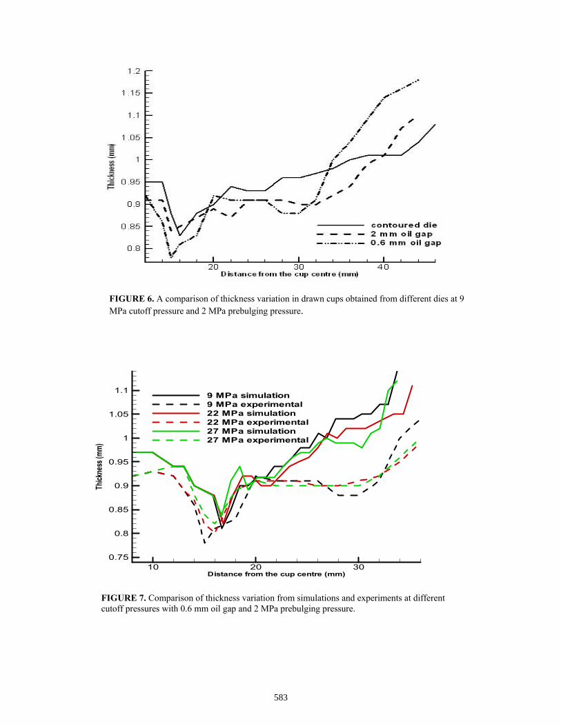
mechanical deep drawing when compared toconventional deep drawing leading to componentswith more uniform thickness distribution. It wasobserved that thinning near the punch corner wouldnot increase rapidly further during drawing like inthe case of conventional deep drawing. A secondthinning region was found at around 30 mm from thecentre of the cup bottom as the prebulging pressureincreased. The drawn cups with 2 MPa prebulgingpressure showed minimum variation in thickness.Fig. 6 shows comparison of thickness variations for2.2 draw ratio for dies with small and medium oilgaps and the modified die. By increasing the oil gap
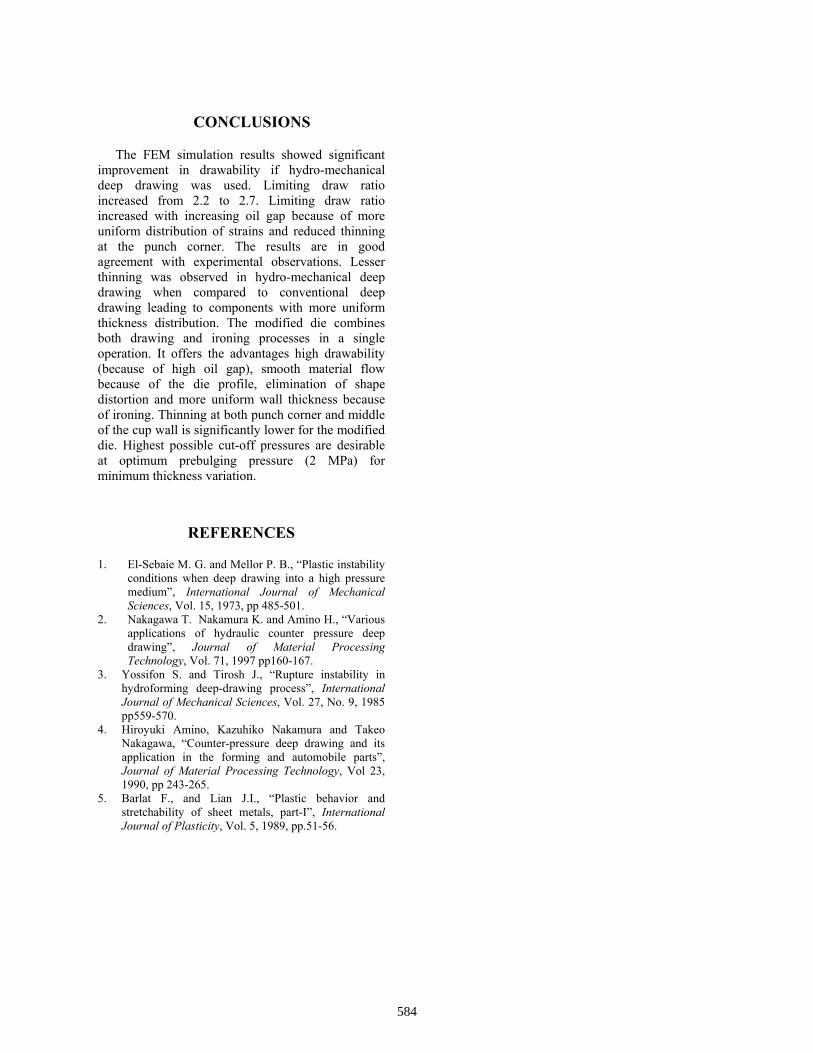
thinning in the cup wall reduces and hence middlefracture is prevented. Thinning at both punch cornerand middle of the cup wall is significantly lower forthe modified die. Fig.7 shows a comparison ofthickness variation obtained from simulations andexperiments for 0.6 mm oil gap, 2 MPa prebulgingpressure and 27 MPa cutoff pressure. As the cut offpressure increased, thinning in the punch cornerreduced and the thickness was more uniform in themiddle of the cup wall. Hence highest possible cut-off pressures are desirable at optimum prebulgingpressure (2 MPa) for minimum thickness variation.
Table 2. LDR at different cut-off pressures with modified die at 2 MPa pre-bulging pressure.
Cut-off pressure (MPa)
LDR (Experimental)
LDR (Simulation)
13
2.48
2.467
22
2.506
2.5
24
2.557
2.53
27
2.61
2.55
FIGURE 4. Prebulging in the blank duringhydro-mechanical deep drawing (contours ofVon Mises stresses)
FIGURE 5. Thickness contours in the cup from simulationof hydro-mechanical deep drawing with 0.6 mm oil gap, 27MPa cutoff pressure and 2 MPa prebulging pressure.
582
Distance from the cup centre (mm)
Thickness(mm)
10 20 300.75
0.8
0.85
0.9
0.95
1
1.05
1.1 9 MPa simulation9 MPa experimental22 MPa simulation22 MPa experimental27 MPa simulation27 MPa experimental
FIGURE 7. Comparison of thickness variation from simulations and experiments at different cutoff pressures with 0.6 mm oil gap and 2 MPa prebulging pressure.
FIGURE 6. A comparison of thickness variation in drawn cups obtained from different dies at 9 MPa cutoff pressure and 2 MPa prebulging pressure.
583
CONCLUSIONS
The FEM simulation results showed significant improvement in drawability if hydro-mechanical deep drawing was used. Limiting draw ratio increased from 2.2 to 2.7. Limiting draw ratio increased with increasing oil gap because of more uniform distribution of strains and reduced thinning at the punch corner. The results are in good agreement with experimental observations. Lesser thinning was observed in hydro-mechanical deep drawing when compared to conventional deep drawing leading to components with more uniform thickness distribution. The modified die combines both drawing and ironing processes in a single operation. It offers the advantages high drawability (because of high oil gap), smooth material flow because of the die profile, elimination of shape distortion and more uniform wall thickness because of ironing. Thinning at both punch corner and middle of the cup wall is significantly lower for the modified die. Highest possible cut-off pressures are desirable at optimum prebulging pressure (2 MPa) for minimum thickness variation.
REFERENCES
1. El-Sebaie M. G. and Mellor P. B., “Plastic instability conditions when deep drawing into a high pressure medium”, International Journal of Mechanical Sciences, Vol. 15, 1973, pp 485-501.
2. Nakagawa T. Nakamura K. and Amino H., “Various applications of hydraulic counter pressure deep drawing”, Journal of Material Processing Technology, Vol. 71, 1997 pp160-167.
3. Yossifon S. and Tirosh J., “Rupture instability in hydroforming deep-drawing process”, International Journal of Mechanical Sciences, Vol. 27, No. 9, 1985 pp559-570.
4. Hiroyuki Amino, Kazuhiko Nakamura and Takeo Nakagawa, “Counter-pressure deep drawing and its application in the forming and automobile parts”, Journal of Material Processing Technology, Vol 23, 1990, pp 243-265.
5. Barlat F., and Lian J.I., “Plastic behavior and stretchability of sheet metals, part-I”, International Journal of Plasticity, Vol. 5, 1989, pp.51-56.
584