numerical simulation of a submerged cylindrical wave
TRANSCRIPT

lable at ScienceDirect
Renewable Energy 64 (2014) 132e143
Contents lists avai
Renewable Energy
journal homepage: www.elsevier .com/locate/renene
Numerical simulation of a submerged cylindrical wave energyconverter
M. Anbarsooz*, M. Passandideh-Fard, M. MoghimanDepartment of Mechanical Engineering, Ferdowsi University of Mashhad, Mashhad 9177948944, Iran
a r t i c l e i n f o
Article history:Received 19 April 2013Accepted 1 November 2013Available online
Keywords:Wave energy converterWave-body interactionsSubmerged cylinderBristol cylinder
* Corresponding author. Tel.: þ98 511 8763304; faxE-mail address: [email protected] (M. Anba
0960-1481/$ e see front matter � 2013 Elsevier Ltd.http://dx.doi.org/10.1016/j.renene.2013.11.008
a b s t r a c t
In this study, a numerical model based on the complete solution of the NaviereStokes equations isproposed to predict the behavior of the submerged circular cylinder wave energy converter (WEC)subjected to highly nonlinear incident waves. The solution is obtained using a control volume approachin conjunction with the fast-fictitious-domain-method for treating the solid objects. To validate themodel, the numerical results are compared with the available analytical and experimental data in variousscenarios where good agreements are observed. First, the free vibrations of a solid object in differentnon-dimensional damping ratios and the free decay of a heaving circular cylinder on the free surface of astill water are simulated. Next, the wave energy absorption efficiency of a circular cylinder WEC calcu-lated from the model is compared with that of the available experiments in similar conditions. The re-sults show that tuning the converter based on the linear theory is not satisfactory when subjected tosteep incident waves while the numerical wave tank (NWT) developed in the current study can beeffectively employed in order to tune the converter in such conditions. The current NWT is able to predictthe wave-body interactions as long as the turbulence phenomena are not important which covers a widerange of Reynolds and Keulegan-Carpenter numbers.
� 2013 Elsevier Ltd. All rights reserved.
1. Introduction
The wave energy as a renewable energy has inspired numerousinventors and motivated many experimental and numerical in-vestigations. Yet, several reviews have been published in this regardtwo of which are the book of McCormik [1] and a recent reviewpaper by Falcao [2]. Although various types of wave energy con-verters (WECs) have been designed, no single technology has yetbeen recognized to be superior to the others.
The design of several WECs is based on the oscillatory motion ofa submerged or floating part against a fixed reference. Dependingon thewater depth, different types ofWECsmight bemore efficientin terms of energy absorption. The vertical force component of thewaves are the main source of energy in the offshore WECs such asthe floating buoys while near-shore devices, like bottom-hingedflaps, utilize the horizontal force component. A device whereboth the horizontal and vertical force components can be absorbedwas first proposed by Evans [3]; this device includes a horizontallyaligned cylinder that can move elliptically during the wave. Hederived a linear theory for the performance of this class of wave
: þ98 511 8626541.rsooz).
All rights reserved.
energy absorbing bodies. The submerged cylinder exhibits a largeefficiency (up to 100% theoretically) in a wide range of wave fre-quencies [3]. Dean [4] and Ogilvie, [5] using linear wave diffractiontheory, showed that no energy is reflected from the cylinderwhether it is fixed or freely buoyant. This fact is also valid for a casewhere the cylinder is constrained by springs and dampers in twoorthogonal directions and the constants of spring and damper arethe same in both directions [3]. Evans showed that for certainconstants of the spring and damper corresponding to a given fre-quency, the transmitted wave would also be eliminated resulting inthe complete absorption of the incident wave energy. Very recently,Heikkinen et al. [6] using the potential flow theory, investigated theeffect of phase shift, cylinder radius, wave height and wave periodon the efficiency of the submerged cylinder wave energy converter.
For wave energy applications, a good agreement has been re-ported experimentally in several studies (see for example [7]) be-tween the results of the linear theory and those of the experimentsin small (H/L < 0.01) to moderate wave steepness (0.01 < H/L < 0.03), where H and L being the wave height and length,respectively. However, for steep waves (H/L > 0.03) or in the waveconditions that excite resonances, due to non-linear and/or viscouseffects, considerable discrepancies have been reported in theliterature. Evans et al. [8] and Davis [9] demonstrated that the lineartheory completely fails to predict the performance of the

M. Anbarsooz et al. / Renewable Energy 64 (2014) 132e143 133
submerged cylindrical wave energy absorbers for steep waves. Thisdrawback of the linear theory is mainly due to its limiting as-sumptions namely assuming the flow to be linear and irrotational,and neglecting the viscosity effects.
A common practice to consider the effects of viscosity is to add adamping term similar to the drag term in the well-knownMorison’sequation [10]. This method has been employed by Davis [9] andBabarit et al. [11]. In this method, however, estimating the drag co-efficient is a major problem. Although there are many experimentalresults available in the literature to determine the drag coefficient,this methodology leads to a poor prediction of the absorption effi-ciency [9] and considerable uncertainties in the results [11]. There-fore, considering a constant value for the drag coefficient for anelliptically moving cylinder will lead to unrealistic wave forces.
In this study, the behavior of a submerged cylinder WEC issimulated using the complete solution of the NaviereStokesequations in conjunction with the fast fictitious domain method[12] for treating the solid objects. The numerical model is a modi-fied version of the one previously developed by Mirzaii andPassandideh-Fard [13] for modeling fluid flows containing a freesurface in presence of an arbitrary moving object. Using this nu-merical model, the wave forces on the submerged cylinder con-taining the viscous drag forces are calculated via solving theNaviereStokes equations in each time step. The results of theproposed model show a good agreement with those of the exper-iments even for steep waves.
2. Mathematical model
2.1. Problem setup
The schematic of the computational domain shown in Fig. 1 is arectangular numerical wave tank (Lc � Hc) equipped with a flap-type wavemaker and two passive damping zones. A solid objectrepresenting the flap-type wavemaker is positioned at x ¼ Xp fromthe left, and the circular cylinder representing the wave absorber isinitially placed at x ¼ Ls in the submergence depth Sd measuredfrom the free surface. The cylinder is moored to the bottom of thetank via springs and dampers aligned at 45 degrees with respect tothe x-axis.
The solid object representing the flap-type wavemaker is forcedto move according to a prescribed harmonic motion in order togenerate a desired wave. The domains of computations based onFig. 1 are considered as: Lc > 8L, Hc > 1.5d, Ld1 ¼ 0.25 m andLd2> 2L. More details on thewave generationmethodology used inthis study is given elsewhere [14]. The generated waves travel to-ward the submerged cylinder and force it to move; as a result, someparts of the wave energy are absorbed by the dampers.
Fig. 1. Schematic of the co
2.2. Fluid flow
The governing equations for fluid flow are the NaviereStokesequations in two-dimensional, Newtonian, incompressible andlaminar flow:
V,V! ¼ 0 (1)
vV!vt
þ V!,VV
! ¼ �1rVpþ 1
rV, s!þ g!þ 1
rF!
b (2)
s! ¼ mh�VV!�þ �
VV!�Ti
(3)
where V!
is the velocity vector, r the density, m the dynamic vis-cosity, p the pressure, s! the stress tensor and F
!b represents body
forces acting on the fluid. The interface is advected using Volume-of-Fluid (VOF) method by means of a scalar field (F), the so-calledliquid volume fraction, defined as:
F ¼8<:
0 in the gas phase0 <; < 1 in the liquid� gas interface1 in the liquid phase
(4)
The discontinuity in F is a Lagrangian invariant, propagating ac-cording to:
dFdt
¼ vFvt
þ V!,VF ¼ 0 (5)
2.3. Solid object treatment
As seen in Fig. 1, the solid objects that move within thecomputational domain are the flap-type wavemaker and the sub-merged circular cylinder which acts as the wave energy absorber.Both objects are modeled via the fast-fictitious-domain method[13] where the fluid flow equations are enforced everywhere in thecomputational domain including fluid and solid zones. This con-ceptual framework leads to a simple geometry and time indepen-dent computational domain which can be discretized by astructured and fixed grid mesh resulting in a considerable reduc-tion of the required time for computations. There are several nu-merical approaches presented based on the fast-fictitious domainmethod such as those of Glowinski et al. [15,16], Patankar [17],Patankar et al. [18] and Sharma and Patankar [12]. The numericalmethod used in this study is a modified version of the Sharma andPatankar model [12] developed by Mirzaei and Passandideh-Fard
mputational domain.
M. Anbarsooz et al. / Renewable Energy 64 (2014) 132e143134
[13]. This method is capable of handling unprescribedmotion of thesolids without solving any additional equation in the computa-tional domain. The no-slip condition on the solideliquid interface isimposed by attributing a high viscosity to the solid objects. In thefirst stage of a computation in each time step, the governingequations of fluid motion are solved everywhere in the computa-tional domain including the solid zone without any additionalequation. Next, the rigid body motion for the submerged cylindercan be obtained by imposing an additional condition that the totallinear and angular momentums in the solid body must beconserved in each time step. For the flap-type wavemaker, how-ever, the flap angular velocity is determined based on a harmonicmotion calculated to generate a desired wave [14]. Then, a velocitychange based on the average values is imposed only within thesolid zones; the change, however, is not projected into the fluiddomain. Considering an average velocity for the solid, leads to anunrealistic slip condition in the solideliquid interface as stated bySharma and Patankar [12]. Therefore, in this study, a high viscosityis attributed to the solid zone [13]. A summary of the computationalprocedure followed in each time step of simulation is given below:
1) The solid object in the computational domain is identified usinga scalar parameter 4s defined as:
4s ¼8<:
0 Out of the solid0 <; < 1 Solid boundary1 Within the solid
(6)
2) The fluid flow equations are solved everywhere in the compu-tational domain including the solid zone. In this step, the den-sity and viscosity in each cell are defined as:
r ¼ Frl þ ð1� F � 4sÞrg þ 4srs (7)
m ¼ Fml þ ð1� F � 4sÞmg þ 4sms (8)
where subscripts l, g and s refer to liquid, gas and solid, respectively.The viscosity of the solid is set by a large magnitude in comparisonwith that of the liquid. This large magnitude of viscosity implicitlyimposes the no-slip condition on the solideliquid interface. It hasbeen shown elsewhere [13] that using a viscosity two orders ofmagnitude larger than that of the fluid is large enough to have anaccurate solid body movement. It should be noted that within thesolid zone, the value of F is set to zero.
3) The average translational and rotational velocities in the solidzones are obtained. For the solid object representing the flap-type wavemaker, these velocities are calculated based on theflap prescribed harmonic motion; while for the solid zone rep-resenting the submerged cylinder they are obtained based onthe conservation of the momentum in the solid using followingintegrals:
Ms V!
s ¼Z
Solid zone
rV!
dc (9)
Isu!
s ¼Z
Solid zone
r!� rV!
dc (10)
The velocity distribution inside the solid zone is then updatedaccordingly. When the velocity in the computational domain isupdated, the interface is advected using Eq. (5).
2.4. Spring and damper forces
The effects of the external forces, which are the spring anddamper forces in this study, on the rigid body motion of the cyl-inder are considered by imposing an additional body force in themomentum equation for the computational cells inside the solidzone. At each time step, this body force per unit mass of the solidobject is determined based on the spring and damper forces of theprevious time step according to the following relation:
a!added ¼P
F!
externalMs
(11)
The above equation is applied in the two orthogonal directionsas:
ax;added ¼P
Fx;externalMs
¼�ksx
�xc;s � xfree
�� cxUs
Ms(12)
ay;added ¼P
Fy;externalMs
¼�ksy
�yc;s � yfree
�� cyVs
Ms(13)
where ksx, ksy, cx, cy are the spring constants anddamping coefficientsin the x and y directions, respectively.Us, Vs andMs are the horizontalvelocity, vertical velocity and themass of the solid object. xc;s, yc;s arethe center positions of the solid cylinder and xfree, yfree are the springfree lengths in the x and y directions, respectively.
2.5. Absorption efficiency
The wave energy absorbed by the cylinder in one wave periodmay be calculated as:
Eabs ¼ZtþT
t
PabsðtÞdt ¼ZtþT
t
F!
wave�t�,V!
s�t�dt (14)
where PabsðtÞ is the instantaneous absorbed power, F!
waveðtÞ thewave excitation force acting on the cylinder, and V
!sðtÞ represents
the cylinder velocity. The total force, F!
totðtÞ, consists of the spring,damper, buoyancy and the wave excitation forces. According to theNewton’s second law:
F!
totðtÞ ¼ F!
springðtÞ þ F!
damperðtÞ þ F!
bouyancyðtÞ þ F!
waveðtÞ
¼ MsdV!
sðtÞdt
(15)
Hence the wave excitation force can be written as:
F!
waveðtÞ ¼ MsdV!
sðtÞdt
� F!
springðtÞ � F!
damperðtÞ � F!
bouyancyðtÞ(16)
The energy absorption efficiency is the ratio of the meanabsorbed power, Pabs, to the total mean wave power, Pw, calculatedas [6]:

M. Anbarsooz et al. / Renewable Energy 64 (2014) 132e143 135
h ¼ PabsPw
¼
1T
24 ZtþT
t
PabsðtÞdt35
18 rwgH
2cg(17)
where T is the wave period, rw thewater density, g the gravitationalacceleration, H the wave height and cg is the wave group velocity.Because of the periodic motion of the cylinder, neither the springforces nor the buoyancy and inertia forces have an effect on themean absorber power; i.e.:
1T
24 ZtþT
t
F!
spring�t�,V!
s�t�dt
35 ¼ 0 (18)
1T
24 ZtþT
t
F!
bouyancyðtÞ,V!
sðtÞdt35 ¼ 0 (19)
1T
24 ZtþT
t
MsdV!
sðtÞdt
,V!
sðtÞdt35 ¼ 0 (20)
Thus, the absorption efficiency can be calculated using thefollowing:
h ¼
1T
24 ZtþT
t
� F!
damperðtÞ,V!
sdt
35
18 rgH
2cg(21)
Since F!
damper tð Þ ¼ �cV!
s tð Þ, therefore:
h ¼
1T
24 ZtþT
t
cV!
s,V!
sdt
35
18 rgH
2cg¼
1T
24 ZtþT
t
cxu2s dt þZtþT
t
cyv2s dt
35
�18 rgH
2� 12,
LT
h1þ 2kd
sinh2kd
i (22)
where L is the wave length, k the wave number and d is the stillwater level.
3. Numerical method
For the discretization of the governing equations, a three-stepprojection method is used in which the continuity and mo-mentum equations are solved in three fractional steps [13]. In thefirst step, the convective and body force terms in the momentumequations are discretized using an explicit scheme. The viscosityand pressure terms in this step are not considered. An intermediatevelocity field, Vnþ1/3, is then obtained as:
V!nþ1=3 � V
!n
dt¼ ��V
!,VV
!�n þ 1rn
F!n
b (23)
In this study, the no-slip condition on the solideliquid interfaceis imposed by attributing a high viscosity to the solid region. As aresult, the allowable time step for numerical simulation willdecrease dramatically if the viscous term discretization is per-formed using an explicit scheme. This fact is due to a linear stabilitytime step constraint for an explicit scheme [19]. Therefore, in thesecond step, an implicit discretization scheme is used to model the
viscous term of themomentum equation to obtain the intermediatevelocity from this step, Vnþ2/3, as:
V!nþ2=3 � V
!nþ1=3
dt¼ 1
rnV,m
��VV!nþ2=3�þ
�VV!nþ2=3�T�
(24)
In this equation, the viscous term is discretized in the fractionaltime step tnþ2/3. This leads to an implicit treatment of the viscoustermwhich, in turn, allows using a large time step for simulation offluids with high viscosities. Eq. (24) is solved using a TDMA (Tri-Diagonal Matrix Algorithm) method to obtain Vnþ2/3.
In the final step, the second intermediate velocity is projected toa divergence free velocity field as:
V!nþ1 � V
!nþ2=3
dt¼ � 1
rnVpnþ1 (25)
The continuity equation is also satisfied for the velocity field at thenew time step:
V,V!nþ1 ¼ 0 (26)
Taking the divergence of Eq. (25) and substituting from Eq. (26)results in a pressure Poisson equation as:
V,
�1rnVpnþ1
�¼ V,V
!nþ2=3
dt(27)
The obtained pressure field can then be used to find the finalvelocity field by applying Eq. (25). The resulting set of equations issymmetric and positive definite; a solution is obtained in each timestep using an Incomplete CholeskyeConjugate Gradient (LDLT)solver [20]. Eq. (5) is used to track the location of the interface andis solved according to the Youngs PLIC algorithm [21]. More detailsregarding the model and the free surface treatment are givenelsewhere [13].
The initial condition considered in this study is a still water withno velocity and no surface waves. The solid cylinder is at its equi-librium position at rest. At the left, right and bottom boundaries ofthe computational domain, as displayed in Fig. 1, the no slip con-dition for the velocity components is imposed. At the top of thedomain, the outlet boundary with atmospheric pressure is used.Two passive absorption zones, one just behind the wavemaker andthe other at the end of the computational domain are considered inthe simulations. The method used for treating these damping re-gions is increased viscosity to a level high enough to effectivelydamp the energy of the incident waves [14].
4. Results and discussion
Certain aspects of the proposed model have been previouslyvalidated in other studies [13,14]. They include the ability of themodel to simulate the interaction of a solid object with a liquid inpresence of a free surface [13] and the wave generation method[14]. In this study, therefore, the new developments in the modelwill be examined. For this purpose, first, an analytical case (freevibrations of a solid object) is considered where the accuracy of themethodology used to apply the external forces to the solid object istested. Next, the problem of the free decay of a heaving circularcylinder is studied and the results are compared with the availableanalytical and experimental data. Finally, the wave energy ab-sorption efficiency at various wave frequencies is compared withthe experimental results of Davis [9].
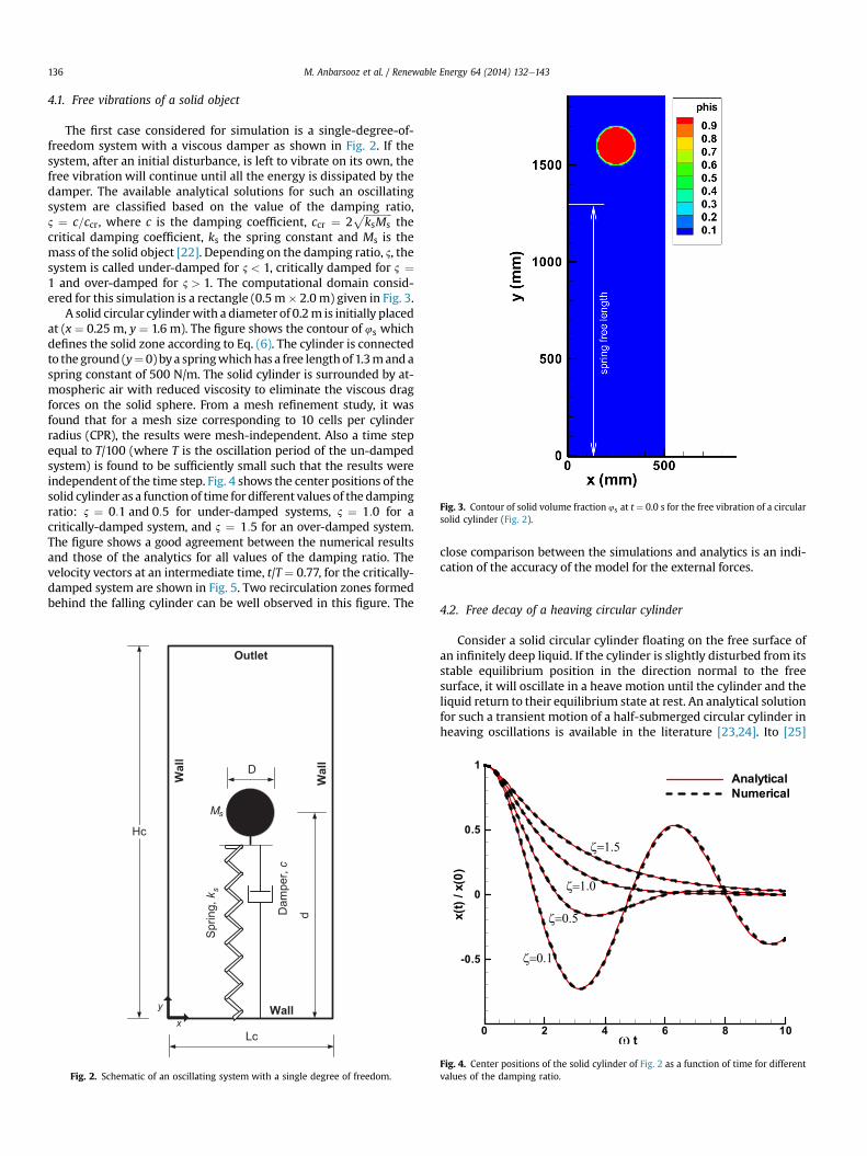
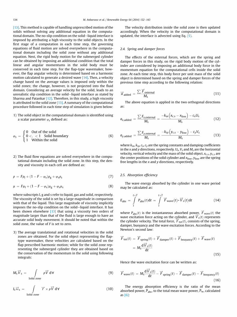
Fig. 3. Contour of solid volume fraction 4s at t ¼ 0.0 s for the free vibration of a circularsolid cylinder (Fig. 2).
M. Anbarsooz et al. / Renewable Energy 64 (2014) 132e143136
4.1. Free vibrations of a solid object
The first case considered for simulation is a single-degree-of-freedom system with a viscous damper as shown in Fig. 2. If thesystem, after an initial disturbance, is left to vibrate on its own, thefree vibration will continue until all the energy is dissipated by thedamper. The available analytical solutions for such an oscillatingsystem are classified based on the value of the damping ratio,2 ¼ c=ccr, where c is the damping coefficient, ccr ¼ 2
ffiffiffiffiffiffiffiffiffiffiffiksMs
pthe
critical damping coefficient, ks the spring constant and Ms is themass of the solid object [22]. Depending on the damping ratio, 2, thesystem is called under-damped for 2 < 1, critically damped for 2 ¼1 and over-damped for 2 > 1. The computational domain consid-ered for this simulation is a rectangle (0.5m� 2.0 m) given in Fig. 3.
A solid circular cylinderwith a diameter of 0.2m is initially placedat (x ¼ 0.25 m, y ¼ 1.6 m). The figure shows the contour of 4s whichdefines the solid zone according to Eq. (6). The cylinder is connectedto the ground (y¼ 0) bya springwhichhas a free lengthof 1.3mand aspring constant of 500 N/m. The solid cylinder is surrounded by at-mospheric air with reduced viscosity to eliminate the viscous dragforces on the solid sphere. From a mesh refinement study, it wasfound that for a mesh size corresponding to 10 cells per cylinderradius (CPR), the results were mesh-independent. Also a time stepequal to T/100 (where T is the oscillation period of the un-dampedsystem) is found to be sufficiently small such that the results wereindependent of the time step. Fig. 4 shows the center positions of thesolid cylinder as a function of time for different values of the dampingratio: 2 ¼ 0:1 and 0:5 for under-damped systems, 2 ¼ 1:0 for acritically-damped system, and 2 ¼ 1:5 for an over-damped system.The figure shows a good agreement between the numerical resultsand those of the analytics for all values of the damping ratio. Thevelocity vectors at an intermediate time, t/T ¼ 0.77, for the critically-damped system are shown in Fig. 5. Two recirculation zones formedbehind the falling cylinder can be well observed in this figure. The
Hc
d
D
Lc
Wall
Wall
x
y
Wall
Outlet
Spring,k
Damper,c
Ms
s
Fig. 2. Schematic of an oscillating system with a single degree of freedom.
close comparison between the simulations and analytics is an indi-cation of the accuracy of the model for the external forces.
4.2. Free decay of a heaving circular cylinder
Consider a solid circular cylinder floating on the free surface ofan infinitely deep liquid. If the cylinder is slightly disturbed from itsstable equilibrium position in the direction normal to the freesurface, it will oscillate in a heave motion until the cylinder and theliquid return to their equilibrium state at rest. An analytical solutionfor such a transient motion of a half-submerged circular cylinder inheaving oscillations is available in the literature [23,24]. Ito [25]
Fig. 4. Center positions of the solid cylinder of Fig. 2 as a function of time for differentvalues of the damping ratio.

Fig. 5. Velocity vectors at t/T ¼ 0.77 for the critically damped vibrations (2 ¼ 1:0) ofthe solid cylinder of Fig. 2.
M. Anbarsooz et al. / Renewable Energy 64 (2014) 132e143 137
also studied the problem experimentally where a good agreementbetween the experimental results and those of the analytics wasobtained. This case with similar conditions, as shown in Fig. 6, hasbeen investigated in this study to better illustrate the capabilities ofthe proposed model. A solid circular cylinder with a radius of 0.1 min awater depth of 1.6 m (d/R¼ 16) is given an initial disturbance of0.03 m (y0/R ¼ 0.3) and is left to oscillate on the water free surface.The dimensions of the computational domain and the boundaryconditions are shown in Fig. 6. The right boundary is selected 4.0 maway from the center of the cylinder; a high viscosity damping zoneis also considered at this boundary to avoid any free surface wavereflections during the simulation. The density of the solid cylinderis half of the water, rs ¼ 500 kg=m3.
The center position of the cylinder as a function of the non-dimensional time, t
ffiffiffiffiffiffiffiffig=R
p, in comparison with the experimental
results of Ito [25] and those of the analytics [24] is shown in Fig. 7.As observed, the cylinder motion in y-direction approximately
1.8 m
1.6m
4.
W
Freeslip
x
y
Ou
Water free
1.63m
0.2 m
Water
Air
Fig. 6. The dimensions of the computational domain and the boundary conditions for the frscale).
follows a harmonic oscillatory motion in time with dampingamplitude [19]. The results of simulations are given for fourdifferent mesh sizes characterized by the number of cells per cyl-inder radius (CPR). As seen from the figure, a mesh size corre-sponding to 20CPR guaranteed grid independent results. Thesimulated results agree well with those of the experiments andanalytics; this validates the model and its underlying assumptions.
4.3. Submerged cylinder wave energy converter
In this section, the numerical model is applied to amore realisticapplication involving the behavior of a submerged circular cylinderWEC, the so-called “Bristol cylinder”. The cases considered aresimilar to those performed by Davis in his experiments [9]. A cir-cular cylinder with a diameter of D ¼ 0.1 m, a water depthd ¼ 0.35 m, and a submergence depth Sd/D ¼2.0 is subjected toseveral incident wave heights of H ¼ 16 and 31 mm with variouswave frequencies ranged from 0.8 to 1.6 Hz. The cylinder is tuned toa frequency of 1.1 Hz based on the linear theory as follows. For agiven wave frequency, u=2p, the power absorption efficiency ismaximized by choosing the spring and damper constants as [8]:
ks;i ¼ ðMs þ aiiÞu2 and ci ¼ bii ði ¼ x; yÞ (28)
where aii is the added mass representing the apparent increase ofthe cylinder inertia due to the liquid, and bii is the damping coef-ficient of the cylinder due to its forced oscillation in the ith direc-tion. The non-dimensional added mass, aii=rc, and thedimensionless damping coefficient, bii=ruc, as a function of thenon-dimensional submergence depth, Sd/R, and the dimensionlesswave number, kR can be found in the literature [26,27].
In order to simulate each case, the dimensions of the computa-tional domain must be adjusted according to the discussion given inSection 2.1. These dimensions according to Fig. 1 for a typical case,which is selected to be the conditions at the frequency of f ¼ 1.4 Hzare: Lc ¼ 8.0 m, Hc ¼ 0.5 m, d ¼ 0.35 m, Ld1 ¼ 0.25 m, Ld2 ¼ 1.0 m,Xp ¼ 0.5 m, Ls ¼ 4.0 m and Sd ¼ 0.1 m. The values of the spring anddamper constants in each direction are determined based on thelinear theory for f¼1.1Hzasksx¼ ksy¼826N/mand cx¼ cy¼20Ns/m.A uniform mesh corresponding to 20 CPR is used in the entirecomputational domain. Also a time step equal toT/100 (where T is the
0.75 m
0 m
all
Wall
tlet
surface
Dampingzone
ee decay of a circular cylinder on the free surface of a still water (the drawing is not to

Fig. 7. The cylinder center position as a function of the non-dimensional time for thefree decay of a circular cylinder on the free surface of a still water (Fig. 6).
t/T
Power(W/m)
0 5 10 150
0.05
0.1
0.15
0.2
0.25
0.3
Power (x)
Power (y)
Fig. 9. Time variations of the absorbed power in the x and y directions, for H ¼ 31 mmand f ¼ 1.4 Hz corresponding to the circular cylinder WEC (Fig. 8).
M. Anbarsooz et al. / Renewable Energy 64 (2014) 132e143138
wave period) is found to be sufficiently small such that the resultswere independent of the time step. The calculation time for this caseis about 48 h on a single core 2.4 GHz PC computer.
The time evolution of the free surface profile as the flap starts itsmotion inside the water is shown in Fig. 8. The solid objects, whichare the flap-type wavemaker and the submerged circular cylinder,are displayed in black. The wavemaker is forced to move with aprescribed simple harmonic motion in order to generate a 31 mm-height wave. The motion of the flapper is initiated using a lineartimeramp with a duration of 2T to eliminate the initial instabilities[14]. The wave-generated motion of the submerged cylinder,however, is calculated based on the momentum conservationequations of the solid as described in Section 2.3.
Fig. 8. Time evolution of the free surface profile for the interactions of the 31
The resultant absorbed power in the x and y-directions as afunction of the non-dimensional time is shown in Fig. 9. Afternearly 13 wave periods (including the initial time ramp) steady-state conditions are achieved. As the figure shows, the absorbedpower in the x-direction is slightly greater than that of the y-di-rection. The total absorbed power is the sum of the power in thetwo orthogonal directions. The simulation is repeated for severalwave frequencies for two wave heights of 16 and 31 mm with thevalues of the spring and damper constants tuned for f ¼ 1.1 Hz. Forthese simulations, the incident wave characteristics including thewave number, wave steepness, wave group-velocity and wave po-wer per meter of the crest are given in Table 1 for the 16-mmwaves
mm incident waves at f ¼ 1.4 Hz with the circular cylinder WEC (Fig. 1).
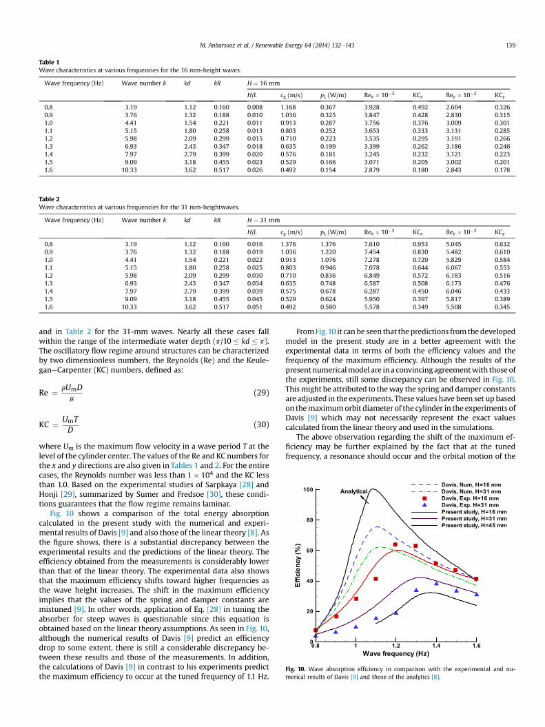
Table 1Wave characteristics at various frequencies for the 16 mm-height waves.
Wave frequency (Hz) Wave number k kd kR H ¼ 16 mm
H/L cg (m/s) pL (W/m) Rex � 10�3 KCx Rey � 10�3 KCy
0.8 3.19 1.12 0.160 0.008 1.168 0.367 3.928 0.492 2.604 0.3260.9 3.76 1.32 0.188 0.010 1.036 0.325 3.847 0.428 2.830 0.3151.0 4.41 1.54 0.221 0.011 0.913 0.287 3.756 0.376 3.009 0.3011.1 5.15 1.80 0.258 0.013 0.803 0.252 3.653 0.333 3.131 0.2851.2 5.98 2.09 0.299 0.015 0.710 0.223 3.535 0.295 3.191 0.2661.3 6.93 2.43 0.347 0.018 0.635 0.199 3.399 0.262 3.186 0.2461.4 7.97 2.79 0.399 0.020 0.576 0.181 3.245 0.232 3.121 0.2231.5 9.09 3.18 0.455 0.023 0.529 0.166 3.071 0.205 3.002 0.2011.6 10.33 3.62 0.517 0.026 0.492 0.154 2.879 0.180 2.843 0.178
Table 2Wave characteristics at various frequencies for the 31 mm-heightwaves.
Wave frequency (Hz) Wave number k kd kR H ¼ 31 mm
H/L cg (m/s) pL (W/m) Rex � 10�3 KCx Rey � 10�3 KCy
0.8 3.19 1.12 0.160 0.016 1.376 1.376 7.610 0.953 5.045 0.6320.9 3.76 1.32 0.188 0.019 1.036 1.220 7.454 0.830 5.482 0.6101.0 4.41 1.54 0.221 0.022 0.913 1.076 7.278 0.729 5.829 0.5841.1 5.15 1.80 0.258 0.025 0.803 0.946 7.078 0.644 6.067 0.5531.2 5.98 2.09 0.299 0.030 0.710 0.836 6.849 0.572 6.183 0.5161.3 6.93 2.43 0.347 0.034 0.635 0.748 6.587 0.508 6.173 0.4761.4 7.97 2.79 0.399 0.039 0.575 0.678 6.287 0.450 6.046 0.4331.5 9.09 3.18 0.455 0.045 0.529 0.624 5.950 0.397 5.817 0.3891.6 10.33 3.62 0.517 0.051 0.492 0.580 5.578 0.349 5.508 0.345
Wave frequency (Hz)
Efficiency(%)
0.8 1 1.2 1.4 1.60
20
40
60
80
100
Davis, Num, H=16 mm
Davis, Num, H=31 mm
Davis, Exp. H=16 mm
Davis, Exp. H=31 mm
Present study, H=16 mm
Present study, H=31 mm
Present study, H=45 mm
Analytical
Fig. 10. Wave absorption efficiency in comparison with the experimental and nu-merical results of Davis [9] and those of the analytics [8].
M. Anbarsooz et al. / Renewable Energy 64 (2014) 132e143 139
and in Table 2 for the 31-mm waves. Nearly all these cases fallwithin the range of the intermediate water depth (p/10 � kd � p).The oscillatory flow regime around structures can be characterizedby two dimensionless numbers, the Reynolds (Re) and the Keule-ganeCarpenter (KC) numbers, defined as:
Re ¼ rUmDm
(29)
KC ¼ UmTD
(30)
where Um is the maximum flow velocity in a wave period T at thelevel of the cylinder center. The values of the Re and KC numbers forthe x and y directions are also given in Tables 1 and 2. For the entirecases, the Reynolds number was less than 1� 104 and the KC lessthan 1.0. Based on the experimental studies of Sarpkaya [28] andHonji [29], summarized by Sumer and Fredsoe [30], these condi-tions guarantees that the flow regime remains laminar.
Fig. 10 shows a comparison of the total energy absorptioncalculated in the present study with the numerical and experi-mental results of Davis [9] and also those of the linear theory [8]. Asthe figure shows, there is a substantial discrepancy between theexperimental results and the predictions of the linear theory. Theefficiency obtained from the measurements is considerably lowerthan that of the linear theory. The experimental data also showsthat the maximum efficiency shifts toward higher frequencies asthe wave height increases. The shift in the maximum efficiencyimplies that the values of the spring and damper constants aremistuned [9]. In other words, application of Eq. (28) in tuning theabsorber for steep waves is questionable since this equation isobtained based on the linear theory assumptions. As seen in Fig. 10,although the numerical results of Davis [9] predict an efficiencydrop to some extent, there is still a considerable discrepancy be-tween these results and those of the measurements. In addition,the calculations of Davis [9] in contrast to his experiments predictthe maximum efficiency to occur at the tuned frequency of 1.1 Hz.
FromFig.10 it can be seen that thepredictions from thedevelopedmodel in the present study are in a better agreement with theexperimental data in terms of both the efficiency values and thefrequency of the maximum efficiency. Although the results of thepresent numericalmodel are ina convincingagreementwith thoseofthe experiments, still some discrepancy can be observed in Fig. 10.Thismight be attributed to theway the spring and damper constantsare adjusted in the experiments. These values have been set up basedon themaximumorbit diameter of the cylinder in the experiments ofDavis [9] which may not necessarily represent the exact valuescalculated from the linear theory and used in the simulations.
The above observation regarding the shift of the maximum ef-ficiency may be further explained by the fact that at the tunedfrequency, a resonance should occur and the orbital motion of the
x/A
y/A
-1 -0.5 0 0.5 1
-1
-0.5
0
0.5
1f=1.6 Hz
f= 1.3 Hz
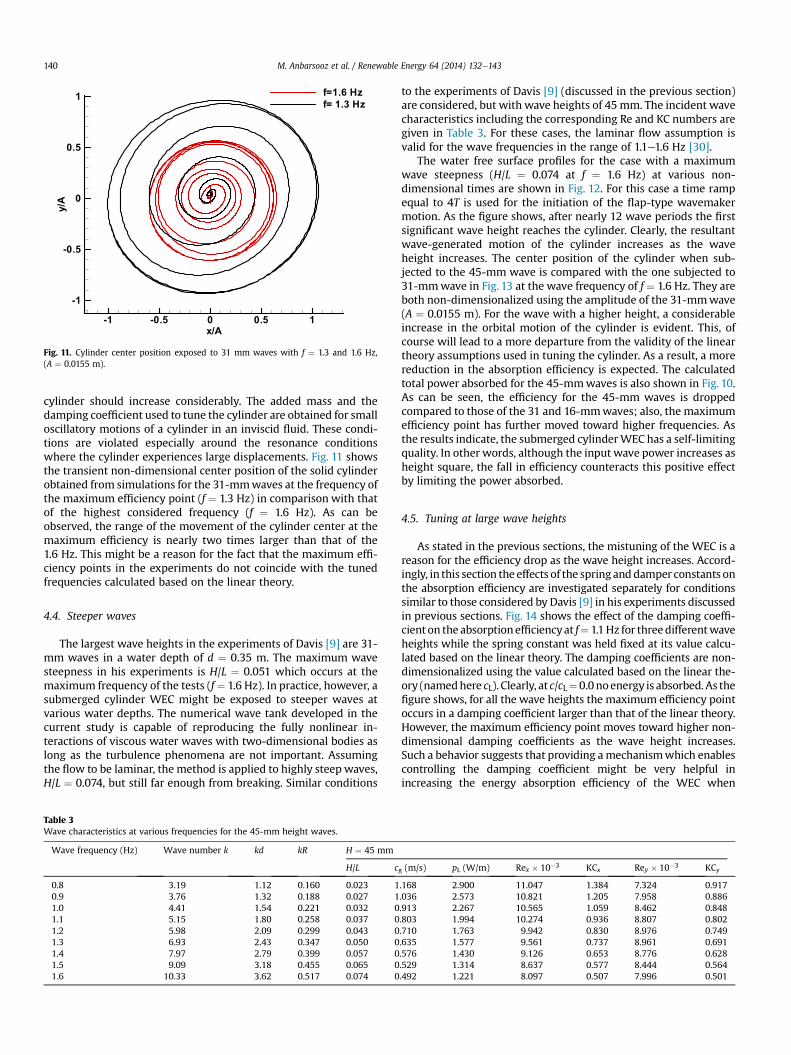
Fig. 11. Cylinder center position exposed to 31 mm waves with f ¼ 1.3 and 1.6 Hz,(A ¼ 0.0155 m).
M. Anbarsooz et al. / Renewable Energy 64 (2014) 132e143140
cylinder should increase considerably. The added mass and thedamping coefficient used to tune the cylinder are obtained for smalloscillatory motions of a cylinder in an inviscid fluid. These condi-tions are violated especially around the resonance conditionswhere the cylinder experiences large displacements. Fig. 11 showsthe transient non-dimensional center position of the solid cylinderobtained from simulations for the 31-mmwaves at the frequency ofthe maximum efficiency point (f ¼ 1.3 Hz) in comparison with thatof the highest considered frequency (f ¼ 1.6 Hz). As can beobserved, the range of the movement of the cylinder center at themaximum efficiency is nearly two times larger than that of the1.6 Hz. This might be a reason for the fact that the maximum effi-ciency points in the experiments do not coincide with the tunedfrequencies calculated based on the linear theory.
4.4. Steeper waves
The largest wave heights in the experiments of Davis [9] are 31-mm waves in a water depth of d ¼ 0.35 m. The maximum wavesteepness in his experiments is H/L ¼ 0.051 which occurs at themaximum frequency of the tests (f¼ 1.6 Hz). In practice, however, asubmerged cylinder WEC might be exposed to steeper waves atvarious water depths. The numerical wave tank developed in thecurrent study is capable of reproducing the fully nonlinear in-teractions of viscous water waves with two-dimensional bodies aslong as the turbulence phenomena are not important. Assumingthe flow to be laminar, the method is applied to highly steep waves,H/L ¼ 0.074, but still far enough from breaking. Similar conditions
Table 3Wave characteristics at various frequencies for the 45-mm height waves.
Wave frequency (Hz) Wave number k kd kR H ¼ 45 mm
H/L c
0.8 3.19 1.12 0.160 0.023 10.9 3.76 1.32 0.188 0.027 11.0 4.41 1.54 0.221 0.032 01.1 5.15 1.80 0.258 0.037 01.2 5.98 2.09 0.299 0.043 01.3 6.93 2.43 0.347 0.050 01.4 7.97 2.79 0.399 0.057 01.5 9.09 3.18 0.455 0.065 01.6 10.33 3.62 0.517 0.074 0
to the experiments of Davis [9] (discussed in the previous section)are considered, but with wave heights of 45mm. The incident wavecharacteristics including the corresponding Re and KC numbers aregiven in Table 3. For these cases, the laminar flow assumption isvalid for the wave frequencies in the range of 1.1e1.6 Hz [30].
The water free surface profiles for the case with a maximumwave steepness (H/L ¼ 0.074 at f ¼ 1.6 Hz) at various non-dimensional times are shown in Fig. 12. For this case a time rampequal to 4T is used for the initiation of the flap-type wavemakermotion. As the figure shows, after nearly 12 wave periods the firstsignificant wave height reaches the cylinder. Clearly, the resultantwave-generated motion of the cylinder increases as the waveheight increases. The center position of the cylinder when sub-jected to the 45-mm wave is compared with the one subjected to31-mmwave in Fig. 13 at the wave frequency of f ¼ 1.6 Hz. They areboth non-dimensionalized using the amplitude of the 31-mmwave(A ¼ 0.0155 m). For the wave with a higher height, a considerableincrease in the orbital motion of the cylinder is evident. This, ofcourse will lead to a more departure from the validity of the lineartheory assumptions used in tuning the cylinder. As a result, a morereduction in the absorption efficiency is expected. The calculatedtotal power absorbed for the 45-mmwaves is also shown in Fig. 10.As can be seen, the efficiency for the 45-mm waves is droppedcompared to those of the 31 and 16-mmwaves; also, the maximumefficiency point has further moved toward higher frequencies. Asthe results indicate, the submerged cylinderWEC has a self-limitingquality. In other words, although the input wave power increases asheight square, the fall in efficiency counteracts this positive effectby limiting the power absorbed.
4.5. Tuning at large wave heights
As stated in the previous sections, the mistuning of the WEC is areason for the efficiency drop as the wave height increases. Accord-ingly, in this section the effects of the spring anddamper constants onthe absorption efficiency are investigated separately for conditionssimilar to those considered by Davis [9] in his experiments discussedin previous sections. Fig. 14 shows the effect of the damping coeffi-cient on the absorptionefficiencyat f¼ 1.1Hz for threedifferentwaveheights while the spring constant was held fixed at its value calcu-lated based on the linear theory. The damping coefficients are non-dimensionalized using the value calculated based on the linear the-ory (namedhere cL). Clearly, at c/cL¼0.0noenergy is absorbed. As thefigure shows, for all the wave heights the maximum efficiency pointoccurs in a damping coefficient larger than that of the linear theory.However, the maximum efficiency point moves toward higher non-dimensional damping coefficients as the wave height increases.Such a behavior suggests that providing amechanismwhich enablescontrolling the damping coefficient might be very helpful inincreasing the energy absorption efficiency of the WEC when
g (m/s) pL (W/m) Rex � 10�3 KCx Rey � 10�3 KCy
.168 2.900 11.047 1.384 7.324 0.917
.036 2.573 10.821 1.205 7.958 0.886
.913 2.267 10.565 1.059 8.462 0.848
.803 1.994 10.274 0.936 8.807 0.802
.710 1.763 9.942 0.830 8.976 0.749
.635 1.577 9.561 0.737 8.961 0.691
.576 1.430 9.126 0.653 8.776 0.628
.529 1.314 8.637 0.577 8.444 0.564
.492 1.221 8.097 0.507 7.996 0.501
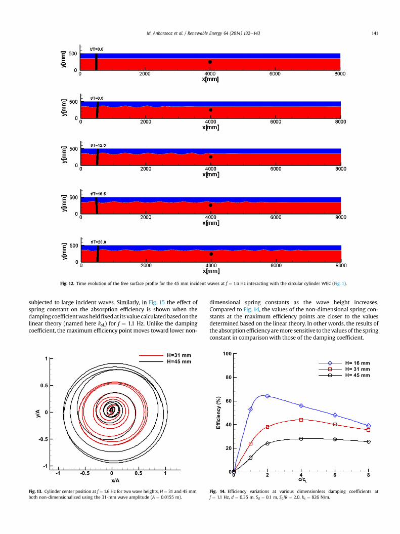
Fig. 12. Time evolution of the free surface profile for the 45 mm incident waves at f ¼ 1.6 Hz interacting with the circular cylinder WEC (Fig. 1).
M. Anbarsooz et al. / Renewable Energy 64 (2014) 132e143 141
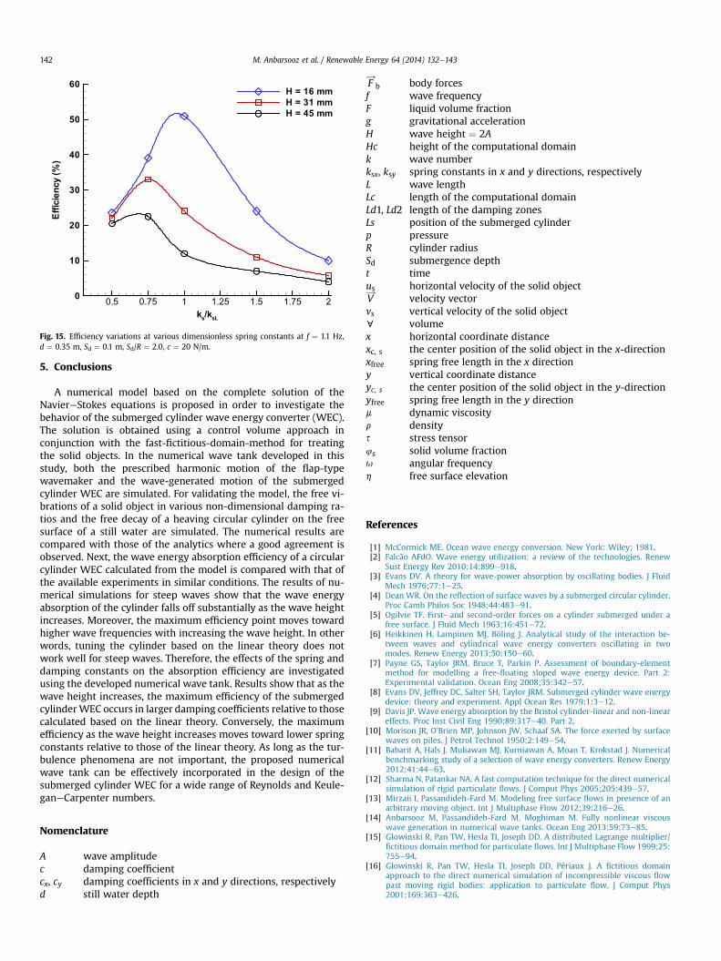
subjected to large incident waves. Similarly, in Fig. 15 the effect ofspring constant on the absorption efficiency is shown when thedampingcoefficientwasheldfixedat its valuecalculatedbasedonthelinear theory (named here ksL) for f ¼ 1.1 Hz. Unlike the dampingcoefficient, the maximum efficiency point moves toward lower non-
x/A
y/A
-1 -0.5 0 0.5 1
-1
-0.5
0
0.5
1H=31 mm
H=45 mm
Fig. 13. Cylinder center position at f ¼ 1.6 Hz for two wave heights, H ¼ 31 and 45 mm,both non-dimensionalized using the 31-mm wave amplitude (A ¼ 0.0155 m).
dimensional spring constants as the wave height increases.Compared to Fig. 14, the values of the non-dimensional spring con-stants at the maximum efficiency points are closer to the valuesdetermined based on the linear theory. In other words, the results oftheabsorptionefficiencyaremore sensitive to thevaluesof the springconstant in comparisonwith those of the damping coefficient.
c/cL
Efficiency(%)
0 2 4 6 80
20
40
60
80
100
H= 16 mm
H= 31 mm
H= 45 mm
Fig. 14. Efficiency variations at various dimensionless damping coefficients atf ¼ 1.1 Hz, d ¼ 0.35 m, Sd ¼ 0.1 m, Sd/R ¼ 2.0, ks ¼ 826 N/m.
ks/ksL
Efficiency(%)
0.5 0.75 1 1.25 1.5 1.75 20
10
20
30
40
50
60
H = 16 mm
H = 31 mm
H = 45 mm
Fig. 15. Efficiency variations at various dimensionless spring constants at f ¼ 1.1 Hz,d ¼ 0.35 m, Sd ¼ 0.1 m, Sd/R ¼ 2.0, c ¼ 20 N/m.
M. Anbarsooz et al. / Renewable Energy 64 (2014) 132e143142
5. Conclusions
A numerical model based on the complete solution of theNaviereStokes equations is proposed in order to investigate thebehavior of the submerged cylinder wave energy converter (WEC).The solution is obtained using a control volume approach inconjunction with the fast-fictitious-domain-method for treatingthe solid objects. In the numerical wave tank developed in thisstudy, both the prescribed harmonic motion of the flap-typewavemaker and the wave-generated motion of the submergedcylinder WEC are simulated. For validating the model, the free vi-brations of a solid object in various non-dimensional damping ra-tios and the free decay of a heaving circular cylinder on the freesurface of a still water are simulated. The numerical results arecompared with those of the analytics where a good agreement isobserved. Next, the wave energy absorption efficiency of a circularcylinder WEC calculated from the model is compared with that ofthe available experiments in similar conditions. The results of nu-merical simulations for steep waves show that the wave energyabsorption of the cylinder falls off substantially as the wave heightincreases. Moreover, the maximum efficiency point moves towardhigher wave frequencies with increasing the wave height. In otherwords, tuning the cylinder based on the linear theory does notwork well for steep waves. Therefore, the effects of the spring anddamping constants on the absorption efficiency are investigatedusing the developed numerical wave tank. Results show that as thewave height increases, the maximum efficiency of the submergedcylinderWEC occurs in larger damping coefficients relative to thosecalculated based on the linear theory. Conversely, the maximumefficiency as the wave height increases moves toward lower springconstants relative to those of the linear theory. As long as the tur-bulence phenomena are not important, the proposed numericalwave tank can be effectively incorporated in the design of thesubmerged cylinder WEC for a wide range of Reynolds and Keule-ganeCarpenter numbers.
Nomenclature
A wave amplitudec damping coefficientcx, cy damping coefficients in x and y directions, respectivelyd still water depth
F!
b body forcesf wave frequencyF liquid volume fractiong gravitational accelerationH wave height ¼ 2AHc height of the computational domaink wave numberksx, ksy spring constants in x and y directions, respectivelyL wave lengthLc length of the computational domainLd1, Ld2 length of the damping zonesLs position of the submerged cylinderp pressureR cylinder radiusSd submergence deptht timeus horizontal velocity of the solid objectV!
velocity vectorvs vertical velocity of the solid objectc volumex horizontal coordinate distancexc, s the center position of the solid object in the x-directionxfree spring free length in the x directiony vertical coordinate distanceyc, s the center position of the solid object in the y-directionyfree spring free length in the y directionm dynamic viscosityr densitys stress tensor4s solid volume fractionu angular frequencyh free surface elevation
References
[1] McCormick ME. Ocean wave energy conversion. New York: Wiley; 1981.[2] Falcão AFdO. Wave energy utilization: a review of the technologies. Renew
Sust Energy Rev 2010;14:899e918.[3] Evans DV. A theory for wave-power absorption by oscillating bodies. J Fluid
Mech 1976;77:1e25.[4] Dean WR. On the reflection of surface waves by a submerged circular cylinder.
Proc Camb Philos Soc 1948;44:483e91.[5] Ogilvie TF. First- and second-order forces on a cylinder submerged under a
free surface. J Fluid Mech 1963;16:451e72.[6] Heikkinen H, Lampinen MJ, Böling J. Analytical study of the interaction be-
tween waves and cylindrical wave energy converters oscillating in twomodes. Renew Energy 2013;50:150e60.
[7] Payne GS, Taylor JRM, Bruce T, Parkin P. Assessment of boundary-elementmethod for modelling a free-floating sloped wave energy device. Part 2:Experimental validation. Ocean Eng 2008;35:342e57.
[8] Evans DV, Jeffrey DC, Salter SH, Taylor JRM. Submerged cylinder wave energydevice: theory and experiment. Appl Ocean Res 1979;1:3e12.
[9] Davis JP. Wave energy absorption by the Bristol cylinder-linear and non-lineareffects. Proc Inst Civil Eng 1990;89:317e40. Part 2.
[10] Morison JR, O’Brien MP, Johnson JW, Schaaf SA. The force exerted by surfacewaves on piles. J Petrol Technol 1950;2:149e54.
[11] Babarit A, Hals J, Muliawan MJ, Kurniawan A, Moan T, Krokstad J. Numericalbenchmarking study of a selection of wave energy converters. Renew Energy2012;41:44e63.
[12] Sharma N, Patankar NA. A fast computation technique for the direct numericalsimulation of rigid particulate flows. J Comput Phys 2005;205:439e57.
[13] Mirzaii I, Passandideh-Fard M. Modeling free surface flows in presence of anarbitrary moving object. Int J Multiphase Flow 2012;39:216e26.
[14] Anbarsooz M, Passandideh-Fard M, Moghiman M. Fully nonlinear viscouswave generation in numerical wave tanks. Ocean Eng 2013;59:73e85.
[15] Glowinski R, Pan TW, Hesla TI, Joseph DD. A distributed Lagrange multiplier/fictitious domain method for particulate flows. Int J Multiphase Flow 1999;25:755e94.
[16] Glowinski R, Pan TW, Hesla TI, Joseph DD, Périaux J. A fictitious domainapproach to the direct numerical simulation of incompressible viscous flowpast moving rigid bodies: application to particulate flow. J Comput Phys2001;169:363e426.

M. Anbarsooz et al. / Renewable Energy 64 (2014) 132e143 143
[17] Patankar NA. A formulation for fast computations of rigid particulate flows. In:Center for Turbulence Research, editor. Annual research briefs. Evanston:Northwestern University; 2001. pp. 185e96.
[18] Patankar NA, Singh P, Joseph DD, Glowinski R, Pan TW. A new formulation ofthe distributed Lagrange multiplier/fictitious domain method for particulateflows. Int J Multiphase Flow 2000;26:1509e24.
[19] Harlow FH, Amsden AA. Fluid dynamics: a LASL monograph (mathematicalsolutions for problems in fluid dynamics). Los Alamos Scientific Laboratoryreport LA 4700; 1971.
[20] Kershaw DS. The incomplete Cholesky-conjugate gradient method for the iter-ative solution of systems of linear equations. J Comput Phys 1978;26:43e65.
[21] Youngs DL. An interface tracking method for a 3D Eulerian hydrodynamicscode; 1984.
[22] Rao SS. Mechanical vibrations. 5th ed. Prentice Hall; 2004.[23] Ursell F. The decay of the free motion of a floating body. J Fluid Mech 1964;19:
305e19.
[24] Maskell SJ, Ursell F. The transient motion of a floating body. J Fluid Mech1970;44:303e13.
[25] Ito S. Study of the transient heave oscillation of a floating cylinder. Depart-ment of Ocean Engineering, Massachusetts Institute of Technology; 1977.
[26] Greenhow M, Ahn SI. Added mass and damping of horizontal circular cylindersections. Ocean Eng 1988;15:495e504.
[27] Evans DV, Porter R. Wave-free motions of isolated bodies and the existence ofmotion-trapped modes. J Fluid Mech 2007;584:225e34.
[28] Sarpkaya T. Force on a circular cylinder in viscous oscillatory flow at lowKeulegandCarpenter numbers. J Fluid Mech 1986;165:61e71.
[29] Honji H. Streaked flow around an oscillating circular cylinder. J Fluid Mech1981;107:509e20.
[30] Sumer BM, Fredsoe J. Hydrodynamics around cylindrical structuresInAdvanced series on Ocean Engineering, vol. 12. World Scientific; 1997.