nuclear radiation hardening associates,...
TRANSCRIPT
Dr. John C. Dunfield
Chief Executive Officer (CEO)
11
(760) 285-2749 (760) 776 1188
Mr. Rick D. May
Vice President and Chief Financial Officer (CFO)
(435) 994-0510 (435) 245-9845
Nuclear Radiation Hardening Associates, LLC
www.nucradhard.com

Ionizing RadiationElectromagnetic Environmental Effects
Nuclear Radiation Hardening Associates, LLC
2
Electromagnetic Environmental Effects
www.nucradhard.com

Introduction
Under the professional leadership of Dr. John C. Dunfield and Mr. Rick D. May, NRH Associates offers complete capability for mitigating the deleterious effects of Ionizing Radiation in electronic equipment vital to the National Defense and military capability. NRHA Ionizing Radiation effects experience for man-made Nuclear Natural Space and Radiation environments include nuclear radiation prompt X-rays,
3
Natural Space and Radiation environments include nuclear radiation prompt X-rays, gammas, and neutrons, delayed gammas, betas, and neutrons, and Solar Flare and Cosmic Radiation protons and heavy ions. And similar to Dr. Aka G. Finci’s E3
experience, includes System Generated Electromagnetic Pulse (SGEMP), which is primarily a result of ionizing X-Ray and gamma ray interaction with system structural materials.
NRHA has significant experience in the design, development, and life cycle hardness of nuclear and natural space radiation hardened military systems. Hardness design and development includes radiation planning, requirements interpretation and flow-down, testing, analysis, design trades, effects mitigation and design guidelines, and radiation transport calculations. Life cycle hardness includes the development and implementation of Hardness Assurance, Hardness Maintenance, and Hardness Surveillance Programs. In addition, NRHA personnel have consulted for over a dozen companies for Booster, EKV, and Space Satellites, taught Electrical Engineering at two universities, and have managed radiation test facilities for Boeing and the Air Force.

Ionizing Radiation Environments and Effects
• Sources of Radiation
– Nuclear Weapon Detonation Environments
• prompt X-rays, gammas, and neutrons
• delayed (and persistent) gammas, betas, and neutrons
– Natural Space Environments (Protons and Heavy Ions)
• Cosmos
• Sun
• Effects Caused by Radiation
4
• Effects Caused by Radiation
– Effects of Nuclear Radiation
• Dose Rate (DR) or Transient Radiation Effects in Electronics (TREE)
• Total Dose in Electronics (TD)
• Neutron Induced Upset (NIU) and Displacement Damage (NDD)
• Electron Caused Electromagnetic Pulse (ECEMP)
• System Generated Electromagnetic Pulse (SGEMP)
• Focal Plane Noise
• Thermo-Mechanical Response (TMR)
• Combined Environment Processes
– Effects of Natural Radiation
• Single Event Effects (SEE)
• Total Dose (TD)
• Electron Caused Electromagnetic Pulse (ECEMP)

LIFE CYCLE SURVIVABILITY
Survivability
Program
Plan
REQUIREMENTSDEVELOPMENT
- A-Spec
Analysis &
UpdateDESIGN SUPPORT
Part Selection
HCI Data
Radiation
Design
Guidelines
V/V Test Plan
Survivability Test
Plan & Procedures
Test Results
Reports
Mission
Performance
HAMS Plan
Test Results
Reports
Training
Procedures
Survivability Engineering Functions
55
Update
- B-Spec
Flowdown
- Documentation- Technology
Assessment
- System
Response
Analyses
- Trade Studies
- Data Needs
- Design Reviews
- Design Guidelines
- Part Testing
- Circuit Testing
- Interface
Penetration Tests
- Data Analysis
VALIDATION/VERIFICATION
HARDNESSASSURANCEMAINTENANCESURVEILLANCE
- Technical Performance
Metrics
- Test Facilities
- B-Spec Validation
- A-Spec Verification
- Test Support
Performance
- Technical Performance
Metrics Documents
- HCI Tracking System
- CM Interfaces
- HCI Tracking
- Training Procedures
- Documentation

Nuclear Weapon Environment Hardening
Electronic systems must continue to operate through or survive the exposure to nuclear weapon
detonation environments
• Experience
– GMD Program OBV nuclear radiation hardening design and development, OBV HAMS
program planning
– Overall GMD (Boeing) survivability program support and Survivability Program Plans
– GMD EKV radiation hardening program
– Nuclear radiation hardening program planning – candidate Boeing MKV
6
– FCS survivability program, strategic nuclear radiation hardening
– ICBM hardness development and HAMS implementation, Minuteman II, Minuteman III,
Minuteman III GRP, Peacekeeper,
– Hardness planning Small ICBM
– Management of the Air Force LMTA Utah radiation test facility
• Hardening: Radiation effects mitigation through electronic piece-part selection and parts type
count minimization, functional and electromechanical hardening including transient radiation
electronic filtering and circumvention, power dump and recovery, EEE part utilization, radiation
shielding, utilization of Hi-Z and Low-Z materials and filled-cables to minimize SGEMP.
• Testing: LINAC and FXR electron/photon parts testing, High Energy X-Ray FXR (PR958,
PR1150) box and system level testing, FBR neutron parts testing, Low Energy FXR
experiments (MBS, Black Jack, Pithon, Double Eagle), and 60Co gamma immersion sources
and 137Cs gamma ray sources.
• Environments and Testing standards: MDA-STD-001, MIL-STD-1766B, MIL-STD-1547B, MIL-
HDBK-814, MIL-HDBK-815, MIL-STD-750E, MIL-STD-883G, and JESD89-3

Natural Radiation Environment Hardening
Electronic systems must continue to operate through or survive the exposure to natural space
radiation environments
• Experience
– GMD Program OBV natural radiation hardening design and development, OBV
HAMS program planning
• Hardness design and development
• Radiation planning – Radiation Hardness Assurance Plan (RHAP)
• Requirements interpretation and flow-down and radiation transport
calculations (CREME96, MCNPX, ITS)
7
calculations (CREME96, MCNPX, ITS)
• Radiation trade studies, Radiation Design Guidelines
• Simulation and Modeling
• Parts testing (Proton and Heavy Ion) and analysis (SEE predictions)
– Overall GMD (Boeing) survivability program support
• Hardening: Radiation effects mitigation through electronic piece-part selection and parts
type count minimization, radiation testing, functional and electromechanical hardening
including EDAC and redundancy, EEE part utilization, and radiation shielding.
• Testing: Parts testing at particle accelerators to perform Cosmic Ray and Solar Flare
proton and heavy ion testing; proton testing at IUCF (Indiana University Cyclotron
Facility) and TRIUMF (TRI-University Meson Facility); heavy ion testing at TAMU (Texas
A&M University) particle accelerator and U.C. Berkeley Accelerator Space Effects (BASE)
Facility particle accelerator.
• Environments and Testing standards: MDA-STD-001, MIL-STD-1547B, MIL-HDBK-814,
MIL-HDBK-815, MIL-STD-750E, MIL-STD-883G, and JESD89-3

-SYS NUC RQMTS
-NATURAL RQMTS
-ASSIST
ENVIRONMENTS
SCENARIO
TRANSPORTED
CAPABILITIES DOCUMENTS
Requirements Development &
Analysis Tools
88
B SPECIFICATION
TRANSPORTED
- MCNPx
- BOXIEMP I&II
- CEPXONLD
- ITS SERIES
- CREME96
- Testable Hardware Toolkit (THTk)
- BOXIEMP I&II
- EM Coupling Tools
- EMA3D
- MHarness
- Simulation & Modeling Tools
- radiation circuit analysis (e.g., SPICE, PSPICE)
- CREME96
- Test Data Bank
HW/SW RESPONSE
TOOLS

Natural Space Natural Space
Radiation:Radiation:
Nuclear Radiation; Fission Nuclear Radiation; Fission
and Thermoand Thermo--Nuclear (shown Nuclear (shown
below) Weapon Detonation:below) Weapon Detonation:
Ionizing Radiation Environments
99

• Sources of Radiation– Natural Space Environments
• Cosmos
• Sun
– Nuclear Weapon Detonation Environments
• Effects Caused by Radiation– Effects of Natural Radiation
• Single Event Effects (SEE)
• Total Dose (TD)
Overview of Radiation Environments And Effects
1010
• Total Dose (TD)
• Electron Caused Electromagnetic Pulse (ECEMP)
– Effects of Nuclear Radiation• Transient Radiation Effects in Electronics (e.g., Dose Rate)
• Total Dose in Electronics (TD)
• Neutron Displacement Damage
• Neutron Induced Upset (NIU)
• System Generated Electromagnetic Pulse (SGEMP)
• Electron Caused Electromagnetic Pulse (ECEMP)
• Focal Plane Noise
• Thermo-Mechanical Response (TMR)
• Combined Environment Processes

Natural Radiation
11
Natural Radiation

• The Solar Cycle 24 Prediction Panel has reached a consensus decision on the prediction of the next solar cycle (Cycle 24). First, the panel has agreed that solar minimum occurred in December, 2008. This still qualifies as a prediction since the smoothed sunspot number is only valid through September, 2008. The panel has
Solar Cycle Progression Presented by the NOAA/Space Weather Prediction Center: Solar Cycle 24 Prediction Update released
May 8, 2009:Solar Flare Activity Predicted to Increase
12
decided that the next solar cycle will be below average in intensity, with a maximum sunspot number of 90. Given the predicted date of solar minimum and the predicted maximum intensity, solar maximum is now expected to occur in May, 2013. Note, this is a consensus opinion, not a unanimous decision. A supermajority of the panel did agree to this prediction
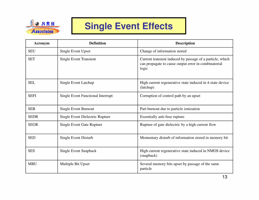
Single Event Effects
Acronym Definition Description
SEU Single Event Upset Change of information stored
SET Single Event Transient Current transient induced by passage of a particle, which
can propagate to cause output error in combinatorial
logic
SEL Single Event Latchup High current regenerative state induced in 4-state device
(latchup)
SEFI Single Event Functional Interrupt Corruption of control path by an upset
13
SEB Single Event Burnout Part burnout due to particle ionization
SEDR Single Event Dielectric Rupture Essentially anti-fuse rupture
SEGR Single Event Gate Rupture Rupture of gate dielectric by a high current flow
SED Single Event Disturb Momentary disturb of information stored in memory bit
SES Single Event Snapback High current regenerative state induced in NMOS device
(snapback)
MBU Multiple Bit Upset Several memory bits upset by passage of the same
particle

Heavy Ion induced Single Event Latchup (SEL)
14
After: Johnston

Heavy Ion Illustrated GCR Single Event Upset (SEU)(Solar Flare can be much larger)
15

• Typically observed in power transistors (MOSFET and bipolar)
• Triggered by ion turning on a biased “OFF” N-channel
• Regenerative feedback produces second breakdown
• High current short between source and drain
Power MOSFET,
With Parasitic npn Bipolar Device
Single Event Burnout
16
Parasitic Bipolar Device
Bipolar Power Transistor
After: Galloway

SEGR Characteristics
• Ion breaks down gate oxide
Conceptual Model
for Gate Rupture
Single Event Gate Rupture
17
• Ion breaks down gate oxide resulting in short between gate and substrate
• Dependent on LET
• Dependent on gate oxide critical field
After: Titus
After: Brews

• Single Event Effects (SEE)
– upsets, damage, and failures that occur mostly in digital
devices, resulting from the ionization created by high-energy
particles traveling through the device X-Rays• Galactic cosmic rays
– Fluence low, solar cycle variation small– Difficult to shield, significant heavy ion component
• Solar Flare Particles
Mitigation of Single Event Effects
18
• Solar Flare Particles– Fluence can be very high– Can be shielded, but very weight expensive, highly variable, and
unpredictable
– Nuclear Radiation Neutron Ionization Upset is a similar
effect (discussed in a later section)
• Mitigation– Part Selection and Testing
– Circuit Design
– Error Detection and Correction
– Radiation Shielding (for Solar Flares only)

Nuclear Radiation
19
Nuclear Radiation
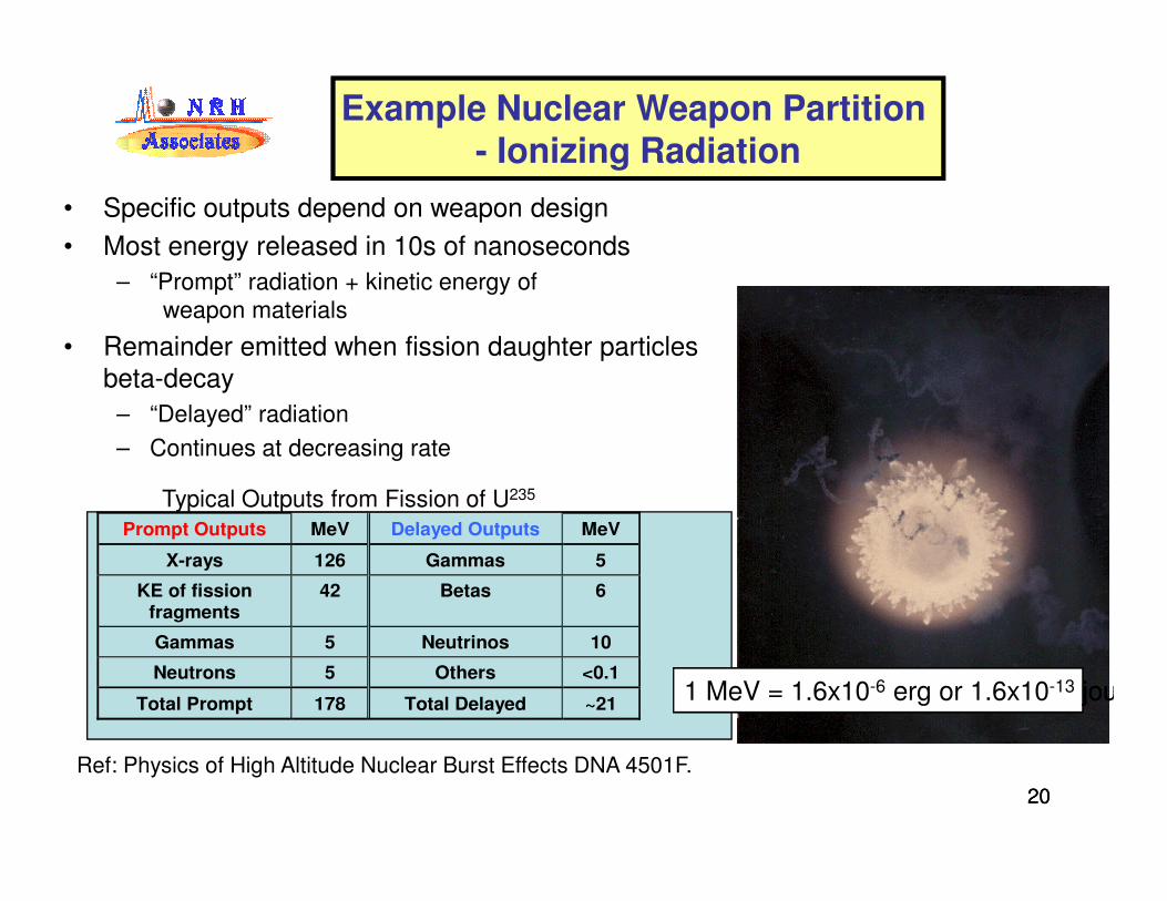
• Specific outputs depend on weapon design
• Most energy released in 10s of nanoseconds
– “Prompt” radiation + kinetic energy of
weapon materials
• Remainder emitted when fission daughter particles
beta-decay
– “Delayed” radiation
– Continues at decreasing rate
Example Nuclear Weapon Partition - Ionizing Radiation
2020
– Continues at decreasing rate
Prompt Outputs MeV Delayed Outputs MeV
X-rays 126 Gammas 5
KE of fission fragments
42 Betas 6
Gammas 5 Neutrinos 10
Neutrons 5 Others <0.1
Total Prompt 178 Total Delayed ~21
Typical Outputs from Fission of U235
Ref: Physics of High Altitude Nuclear Burst Effects DNA 4501F.
joul1 MeV = 1.6x10⁻⁶ erg or 1.6x10⁻¹³ joul

Prompt Gamma
Neutrons
Environm
ents
(Rela
tive S
cale
)X-rays
Debris electron
Nuclear Radiation Environments Extend Over Long Time Scales
2121
Hardening must consider both levels and time line
Delayed gamma
Delayed neutron
10-7 10-5 10-3 10-1 101 103 105
NW
E
Environm
ents
(Rela
tive S
cale
)
Debris electron
Normalized Time
Circumvention & Recovery

X-Rays & Gamma Rays
Typical Prompt Dose Rate Latch-up And Burnout
2222
Latch-Up PathSilicon Damage
X-Rays & Gamma Rays
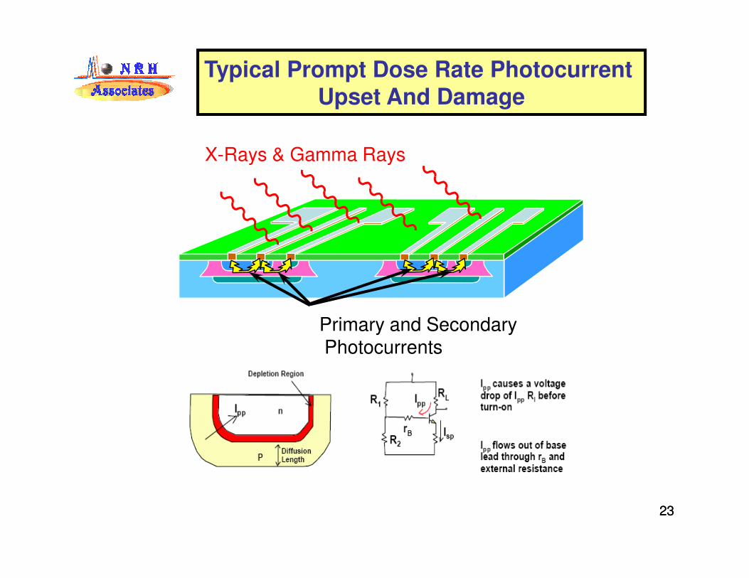
Typical Prompt Dose Rate Photocurrent Upset And Damage
2323
Primary and SecondaryPhotocurrents

Commercial Dose Rate Tolerance
2424Reference: M. Rose, “Updated Bar Charts of Device Radiation
Thresholds," Physitron Corp. San Diego, CA, 1990.

Parts Feature Size and Increased Radiation Sensitivity : Latest SRAM is 65 to 32 nm
2525E. Petersen and P. Marshall, “Single Event Phenomena in the Space and SDI
Arena,”J. Rad. Effects, Res. & Eng., Vol. 6, No. 1, 1988.

Mitigation of Nuclear Radiation Effects
Effect Mitigation
Dose Rate (TREE) and Total
Dose �Part Selection and Testing
�Radiation Shielding (to Bremsstrahlung and/or Gamma Limit, and Self Shielding)
�Circumvention, Power Dump & Recovery
SEE and NIU�Part Selection and Testing
�Circuit Design (e.g., TMR, EDAC)
�Shielding (for Solar Flares only)
�Material Selection
26
�Material Selection
ECEMP and external SGEMP�RF Grounding and Shielding
�Conducting Surface &Terminal Protection
�Low-Response Cables (Internal SGEMP)
�Radiation Shielding
Internal SGEMP�Material Selection – low Z coatings
�Circuit Board Design
�Box Enclosure Design – High Z shield coated with Low Z
�Grounding Design
�Radiation Shielding
Thermo-Mechanical Response
(TMR) �Material Selection
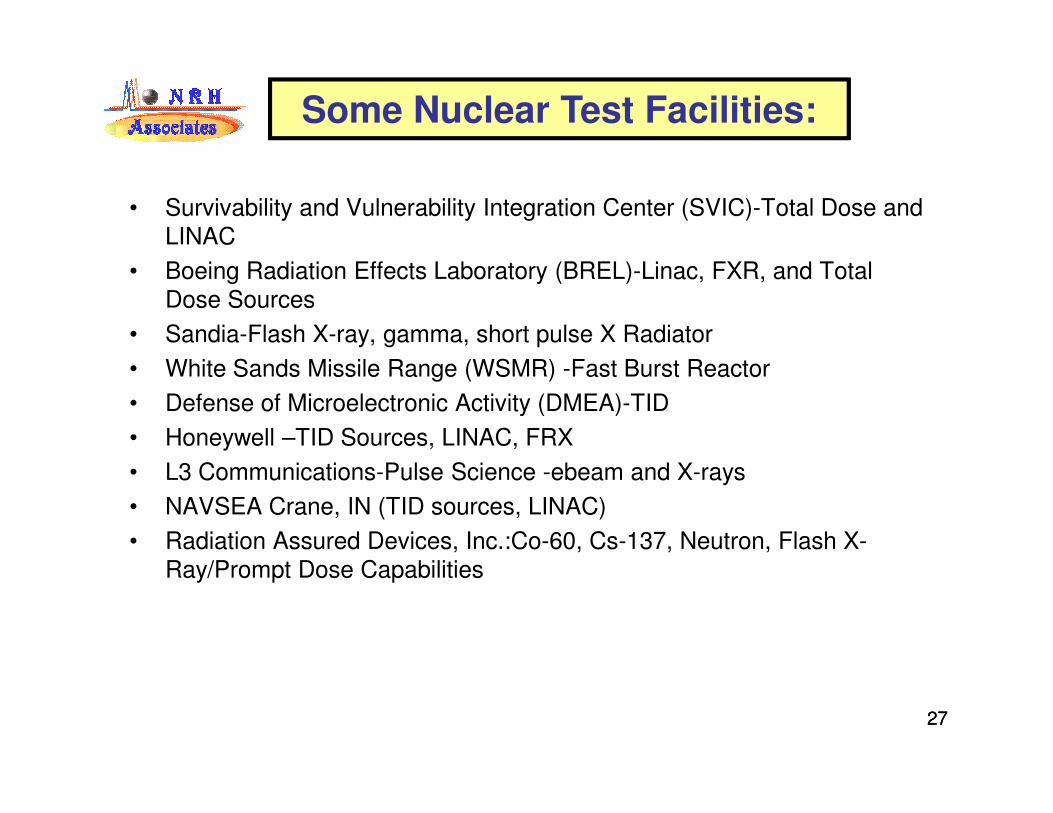
• Survivability and Vulnerability Integration Center (SVIC)-Total Dose and
LINAC
• Boeing Radiation Effects Laboratory (BREL)-Linac, FXR, and Total
Dose Sources
• Sandia-Flash X-ray, gamma, short pulse X Radiator
• White Sands Missile Range (WSMR) -Fast Burst Reactor
• Defense of Microelectronic Activity (DMEA)-TID
Some Nuclear Test Facilities:
2727
• Defense of Microelectronic Activity (DMEA)-TID
• Honeywell –TID Sources, LINAC, FRX
• L3 Communications-Pulse Science -ebeam and X-rays
• NAVSEA Crane, IN (TID sources, LINAC)
• Radiation Assured Devices, Inc.:Co-60, Cs-137, Neutron, Flash X-
Ray/Prompt Dose Capabilities

Example of Nuclear Test Facilities:
2828

Example of Heavy Ion Test Facilities:
2929