ntsc: nice technology, super color jim blinn, cal tech ieee computer graphics and applications,...
Post on 19-Dec-2015
216 views
TRANSCRIPT
NTSC: Nice Technology, Super Color
Jim Blinn, Cal TechIEEE Computer Graphics and Applications, 13(2):17-23, 1993
Presentation by Andy RovaCMPT 820February 22, 2005
February 22, 2005 Andy Rova CMPT 820 2
Overview
• Introduction
• Historical factors in the development of black and white television
• Description of broadcast television signals
• NTSC color encoding

February 22, 2005 Andy Rova CMPT 820 3
Introduction: NTSC coding
• NTSC: National Television Standards committee
• Standard encoding scheme for television signals in the United States and Canada (NTSC Countries)
• NTSC is often criticized, but according to Blinn “NTSC encoding…is one of the most amazing technical achievements of our time…Done well, it can look really good”
February 22, 2005 Andy Rova CMPT 820 4
History of NTSC coding
• The original constraints on television:– Wireless interface
• Must deliver image and sound information in the form of a broadcast radio transmission
– CRT (raster) display• Initial CRTs technologically limited to ~0.5 m• Viewing distance assumed to be ~3 m• Therefore the limits of human vision dictate that a
“good” quality picture must have spatial resolution of at least several hundred lines per frame

February 22, 2005 Andy Rova CMPT 820 5
History of NTSC coding
• Constraints continued:– 4:3 aspect ratio desired– Local power-line frequencies can cause
undesirable artifacts• Vertical CRT rate set to match power-line rate
(60Hz in North America, 50 Hz in Europe)
February 22, 2005 Andy Rova CMPT 820 6
History of NTSC coding
• Transmitting a complete frame (400-500 lines) at 60 Hz requires an unacceptably wide broadcast channel
• 2:1 interlacing used instead– Divide a frame into fields containing even-numbered
and odd-numbered lines– Refresh each field at 60 Hz– Human persistence of vision creates the illusion of the
full vertical resolution being refreshed– Simple form of lossy compression!
February 22, 2005 Andy Rova CMPT 820 7
History of NTSC coding
• North American/Japanese standard:– 525 lines per frame– 60 Hz field rate
• European standard:– 625 lines per frame– 50 Hz field rate
• We are still talking about black and white: “NTSC” and “PAL/SECAM” refer to specific methods of color encoding, so the standards above are properly referred to as “525/60” and “625/50”
February 22, 2005 Andy Rova CMPT 820 8
History of NTSC coding
• How to transmit these images as a radio signal?– 485 of the original 525 lines are available for
“active” video (the other 40 are vertical blanking intervals)
– Assuming a Kell factor of 0.7, the system should deliver (485)(0.7) = 340 lines of vertical resolution
– 4:3 ratio implies (4/3)(340) = 453 “pixels” for each horizontal line
February 22, 2005 Andy Rova CMPT 820 9
History of NTSC coding
• Radio transmission continued:– Recall:
• Lines per frame: 525• Lines per field (2:1 interlacing): (525)/(2) = 262.5
– Therefore, line rate = (262.5 lines/field)(60 fields/s) = 15750 Hz
– 20% of the line time is required for horizontal blanking/retrace
– Recall horizontal resolution is ~453 “pixels”• This implies a maximum of 227 black/white cycles
per line (the highest frequency image possible)
February 22, 2005 Andy Rova CMPT 820 10
History of NTSC coding• Radio transmission continued:
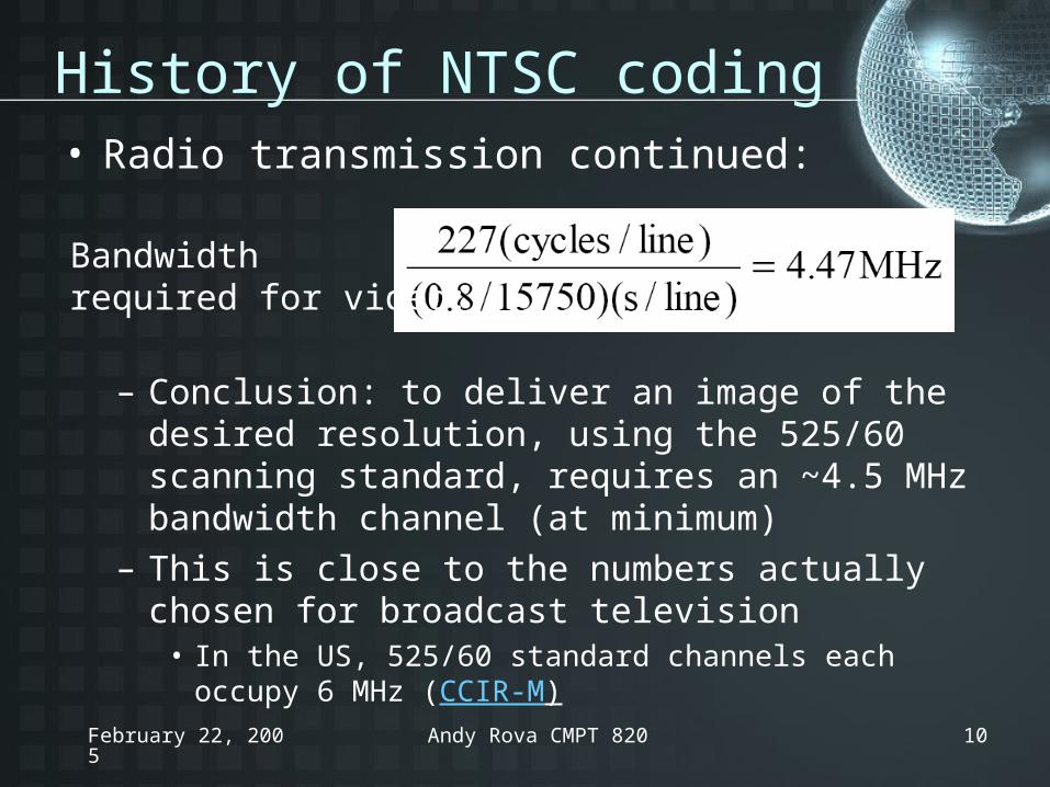
– Conclusion: to deliver an image of the desired resolution, using the 525/60 scanning standard, requires an ~4.5 MHz bandwidth channel (at minimum)
– This is close to the numbers actually chosen for broadcast television
• In the US, 525/60 standard channels each occupy 6 MHz (CCIR-M)
Bandwidth required for video:

February 22, 2005 Andy Rova CMPT 820 11
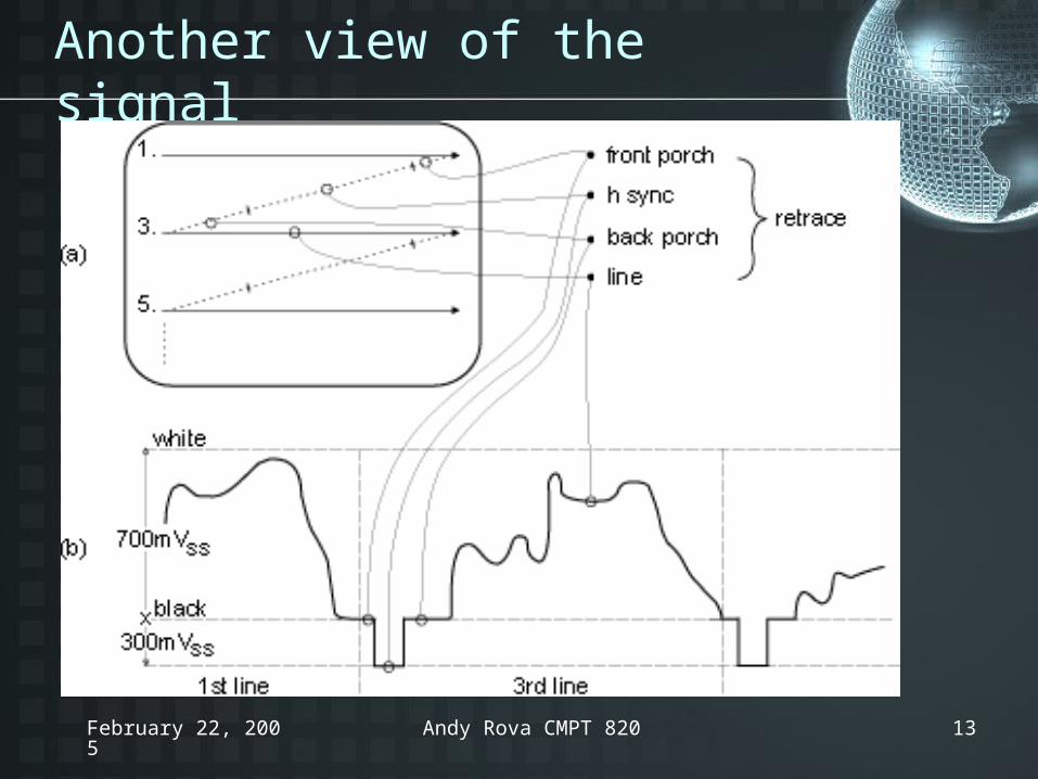
Broadcast signal modulation
• Negative modulation– Increase in luminance = decrease in depth of
modulation– The “blacker” portions of the image are transmitted at
a higher percentage of modulation than the “whiter” portions
– When to start a new line, field or frame?• Need “sync” pulses
– Sync pulses are excursions below the level established for black
• Therefore the highest modulation occurs at the sync pulses, and the receiver is more likely to deliver good reception in the presence of noise

February 22, 2005 Andy Rova CMPT 820 12
A television signal
February 22, 2005 Andy Rova CMPT 820 13
Another view of the signal
February 22, 2005 Andy Rova CMPT 820 14
History of NTSC coding
• Backwards compatibility– When color television was introduced, the
new signals had to maintain compatibility with existing black and white TV sets
– Also, a black and white signal fed to a new color TV had to produce a black and white picture
– Finally, the new signal had to fit into the same bandwidth as the original black and white signal (including audio!)

February 22, 2005 Andy Rova CMPT 820 15
Black and White Signal in Frequency Space
Macrostructure: horizontal detail (line rate)
Microstructure:vertical detail(frame rate)
February 22, 2005 Andy Rova CMPT 820 16
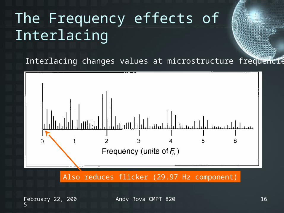
The Frequency effects of Interlacing
Also reduces flicker (29.97 Hz component)
Interlacing changes values at microstructure frequencies:
February 22, 2005 Andy Rova CMPT 820 17
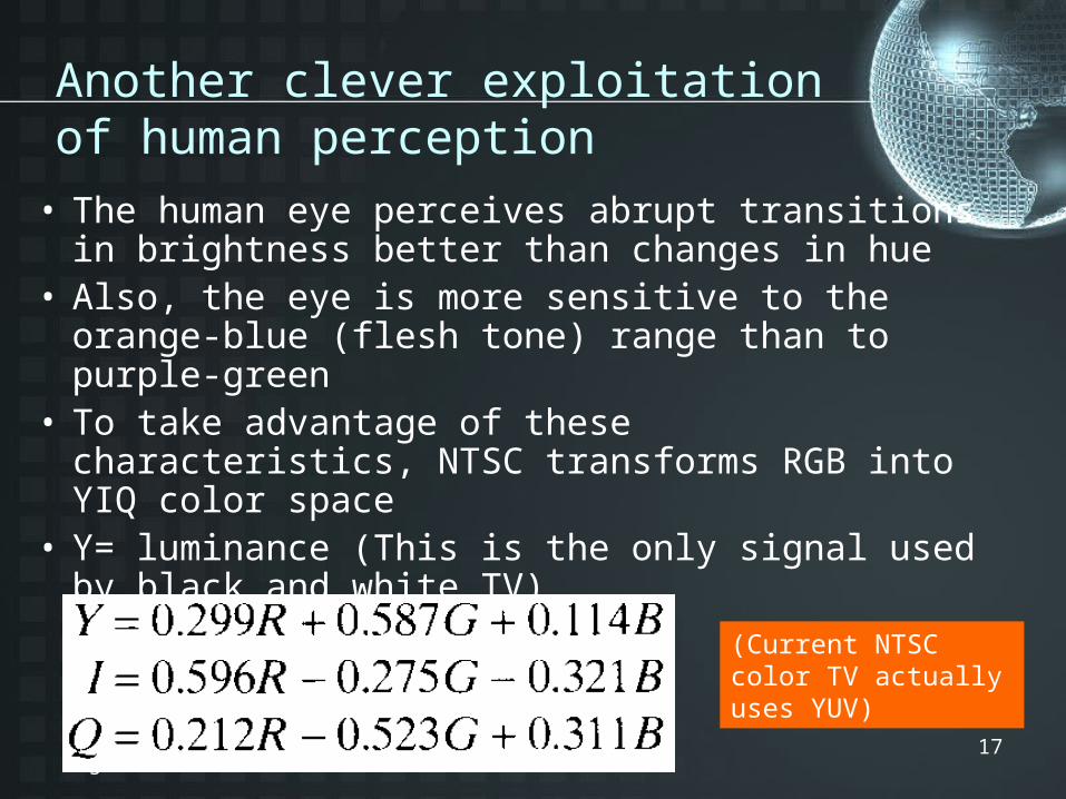
Another clever exploitation of human perception
• The human eye perceives abrupt transitions in brightness better than changes in hue
• Also, the eye is more sensitive to the orange-blue (flesh tone) range than to purple-green
• To take advantage of these characteristics, NTSC transforms RGB into YIQ color space
• Y= luminance (This is the only signal used by black and white TV)
(Current NTSC color TV actually uses YUV)
February 22, 2005 Andy Rova CMPT 820 18
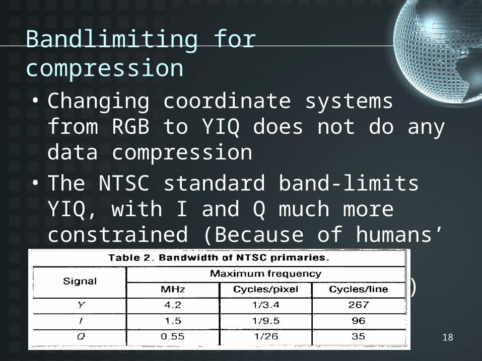
Bandlimiting for compression
• Changing coordinate systems from RGB to YIQ does not do any data compression
• The NTSC standard band-limits YIQ, with I and Q much more constrained (Because of humans’ reduced spatial color vision acuity, as mentioned earlier)
February 22, 2005 Andy Rova CMPT 820 19
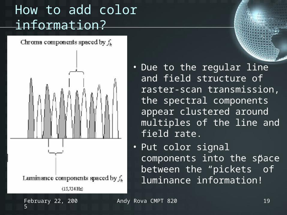
How to add color information?
• Due to the regular line and field structure of raster-scan transmission, the spectral components appear clustered around multiples of the line and field rate.
• Put color signal components into the space between the “pickets” of luminance information!
February 22, 2005 Andy Rova CMPT 820 20
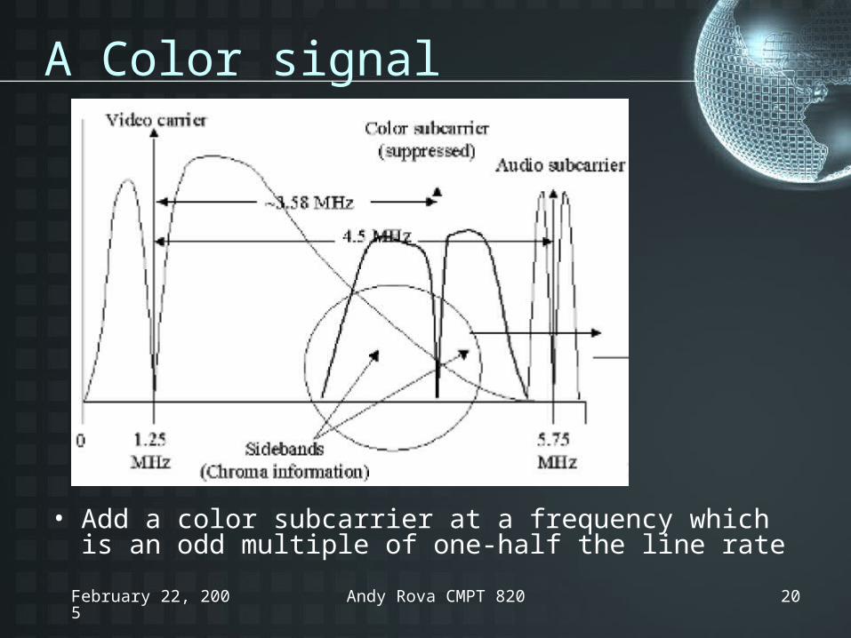
A Color signal
• Add a color subcarrier at a frequency which is an odd multiple of one-half the line rate
February 22, 2005 Andy Rova CMPT 820 21
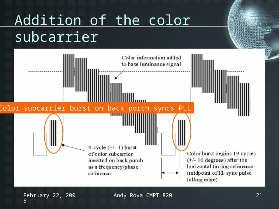
Addition of the color subcarrier
Color subcarrier burst on back porch syncs PLL
February 22, 2005 Andy Rova CMPT 820 22
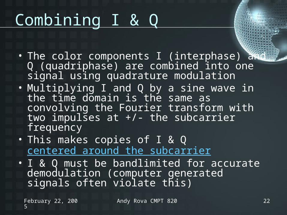
Combining I & Q
• The color components I (interphase) and Q (quadriphase) are combined into one signal using quadrature modulation
• Multiplying I and Q by a sine wave in the time domain is the same as convolving the Fourier transform with two impulses at +/- the subcarrier frequency
• This makes copies of I & Q centered around the subcarrier
• I & Q must be bandlimited for accurate demodulation (computer generated signals often violate this)
subcarrierF

February 22, 2005 Andy Rova CMPT 820 23
Color and Audio
• Note that the new color information comes very close to the audio components at the upper end of the channel
• To avoid mutual interference, the chroma subcarrier was shifted down by a factor of 1000/1001

February 22, 2005 Andy Rova CMPT 820 24
Decoding NTSC
• Cheapest method: low pass filter with 3MHz cutoff to get rid of chroma– But also removes some of the high frequency
luminance data, and blurs the image
• If some color signal remains in the recovered Y values, it will look like dots crawling up vertical edges – “chroma crawl”
• If some luminance signal remains in the separated chroma values, it will appear that rainbows are superimposed on what should be monochrome
February 22, 2005 Andy Rova CMPT 820 25
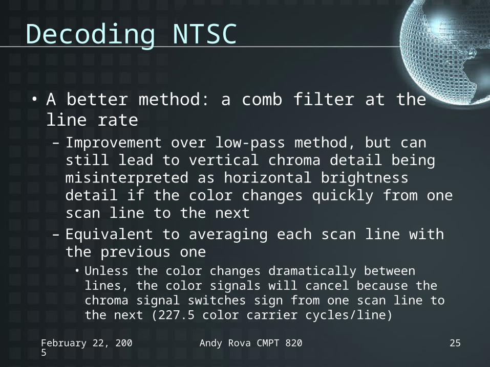
Decoding NTSC
• A better method: a comb filter at the line rate– Improvement over low-pass method, but can still lead
to vertical chroma detail being misinterpreted as horizontal brightness detail if the color changes quickly from one scan line to the next
– Equivalent to averaging each scan line with the previous one
• Unless the color changes dramatically between lines, the color signals will cancel because the chroma signal switches sign from one scan line to the next (227.5 color carrier cycles/line)

February 22, 2005 Andy Rova CMPT 820 26
Decoding NTSC
• Best separation of Y and C: a comb filter at the frame rate– Equivalent to averaging each pixel with the
same pixel from the previous and subsequent frames (chroma changes sign from frame to frame as well as line to line)
– Expensive monitors switch between comb filters at the line and frame rates as needed
February 22, 2005 Andy Rova CMPT 820 27
Conclusion
• NTSC color TV is a system that utilizes many clever methods to deal with the constraints imposed upon it
• When preparing artificial computer images for NTSC presentation, an awareness of the standard can help ensure good results– Filter out high frequencies before encoding!

February 22, 2005 Andy Rova CMPT 820 28

February 22, 2005 Andy Rova CMPT 820 29
NTSC Countries
• USA, Antigua, Bahamas, Barbados, Belize, Bermuda, Bolivia, Burma, Canada, Chile, Colombia, Costa Rica, Cuba, Dominican Republic, Ecuador, El Salvador, Greenland, Guam, Guatemala, Guyana, Honduras, Jamaica, Japan, South Korea, Mexico, Netherlands Antilles, Nicaragua, Panama, Peru, Philippines, Puerto Rico, St. Vincent & the Grenadines, St. Kitts, Saipan, Samoa, Surinam, Taiwan, Tobago, Trinidad, Venezuela, Virgin Islands (back)
February 22, 2005 Andy Rova CMPT 820 30
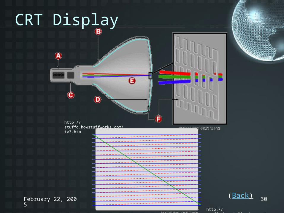
CRT Display
http://stuffo.howstuffworks.com/tv3.htm
http://stuffo.howstuffworks.com/tv7.htm
(Back)
February 22, 2005 Andy Rova CMPT 820 31
Definition: Kell factor
• The effects of interlacing and device constraints reduce the quality of the image that is actually delivered
• The Kell factor is the ratio between actual delivered resolution (under ideal conditions) and the number of lines transmitted per frame
• Television systems are assumed to operate at a Kell factor of ~0.7 (back to History of NTSC)
February 22, 2005 Andy Rova CMPT 820 32
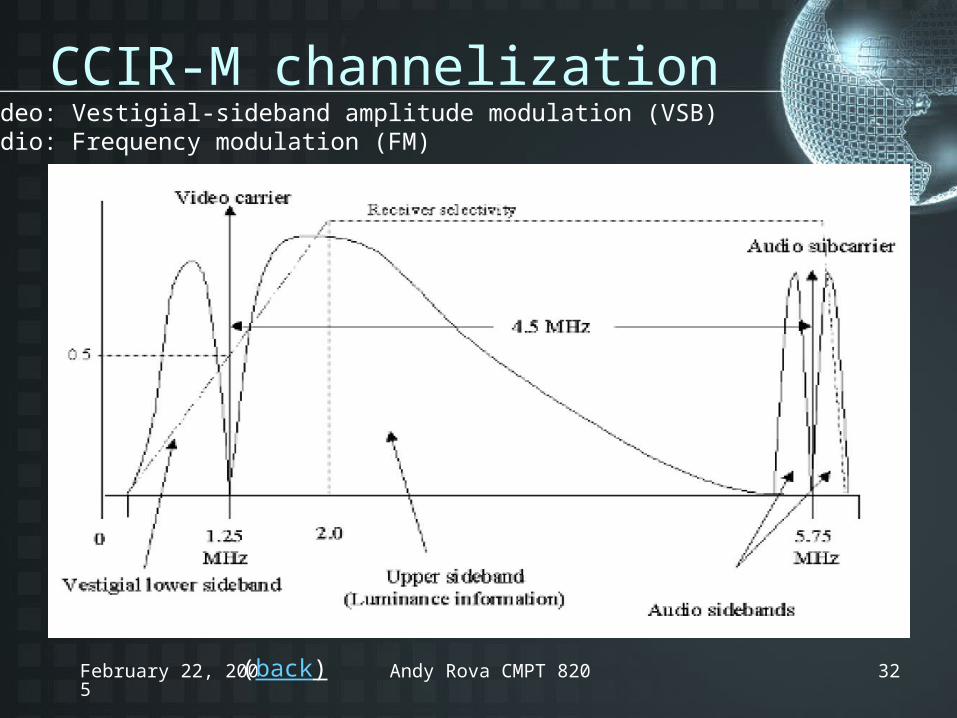
CCIR-M channelization
(back)
Video: Vestigial-sideband amplitude modulation (VSB)Audio: Frequency modulation (FM)