ntpc-sail power company - rites. bid.pdf · connectors conforming to brs:930a, irs:s 34 ......
TRANSCRIPT
NSPCL
NTPC-SAIL Power Company Private Limited
NSPCL
TENDER
FOR
THE WORK
“DESIGN, EXECUTION, TESTING AND COMMISSIONING OF CENTRAL PANEL WITH MACL SIGNALLING AND OTHER ASSOCIATED WORKS AT
INPLANT YARD OF PRIVATE RLY. SIDING AT BHILAI, INCLUDING SUPPLY OF MATERIALS”
(TENDER No. RITES/CO/S&T/NSPCL)
FINANCIAL BID
Volume – III
(BILL OF QUANTITIES)
CONSTRUCTION AGENCY RITES LTD.
(A Government of India Enterprise) RITES BHAVAN, PLOT NO.1 SECTOR – 29,
GURGAON – 122001, HARYANA

NSPCL
BESCL SIGNALLING ARRANGEMENTS AT INPLANT
BILL OF QUANTITIES SCHEDULE-"A"
SUPPLY ITEMS (SIGNALLING) S.No. Description Unit Qty Rate in
digits (In Rs.)
Rate in Words
Total Amou
nt (In
Rs.)
SUPPLY OF RELAYS 1 (a) Relay, Non-AC immune, plug-in type, Style "QN1", Neutral
line, 24V DC 12F, 4B contracts, front and back contacts metal to carbon with plug board, retaining clip & connectors conforming to BRS:930A, IRS:S 34 & IRS:S 23. The interlocking code for this unit shall be ABCDE. Inspection by RDSO.
Nos. 75
(b) Relay, Non-AC Immune, plug-in type, Style "QN1", Neutral line, 24V DC 8F, 8B contracts, front and back contacts metal to carbon with plug board, retaining clip & connectors conforming to BRS:930A, IRS:S 34 & IRS:S 23. The interlocking code for this unit shall be ABCDF. Inspection by RDSO.
Nos. 50
(c) Relay, AC Immune, plug-in type, Style "QNAI", Neutral line, 24V DC 12F, 4B contracts, front and back contacts metal to carbon with plug board, retaining clip & connectors conforming to BRS:931A, IRS:S 60, IRS:S 34 & IRS:S 23. The interlocking code for this unit shall be ABDFH. Inspection by RDSO.
Nos. 50
(d) Relay, AC Immune, plug-in type, Style "QNAI", Neutral line, 24V DC 8F, 8B contracts, front and back contacts metal to carbon with plug board, retaining clip & connectors conforming to BRS:931A, IRS:S 60, IRS:S 34 & IRS:S 23. The interlocking code for this unit shall be ABDGH. Inspection by RDSO.
Nos. 50
(e) Relay, Non-AC Immune, plug-in type, Style "QNN1", Twin Neutral line, 24V DC 6F, 2B contracts each for LH and RH, Front and back contacts metal to carbon, complete with plug-board, retaining clip and connectors conforming to BRS:960A, IRS:s 34 & IRS:S 23. The interlocking code for this unit shall be ACDEK. Inspection by RDSO.
Nos. 25
(f) Relay, Non-AC Immune, plug-in type, Style "QNN1", Twin Neutral line, 24V DC 4F, 4B contracts each for LH and RH, Front and back contacts metal to carbon, complete with plug-board, retaining clip and connectors conforming to BRS:960A, IRS:s 34 & IRS:S 23. The interlocking code for this unit shall be ACEHK. Inspection by RDSO.
Nos. 25
(g) Relay, AC Immune, plug-in type, style "QNNA1", Twin neutral line, 24V DC 6F, 2B contacts each for LH and RH, Front and back contacts metal to carbon, complete with plug-board, retaining clip and connectors conforming to BRS:960A, IRS:S:34 & IRS:S:23. The interlocking code for this unit shall be CDEHK. Inspection by RDSO.
Nos. 25
NSPCL
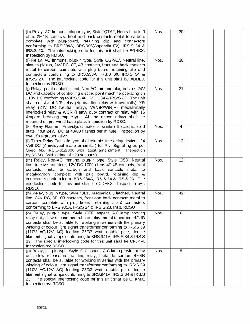
(h) Relay, AC Immune, plug-in type, Style "QTA2; Neutral track, 9 ohm, 2F.1B contacts, front and back contacts metal to carbon, complete with plug-board, retaining clip and connectors conforming to BRS:939A, BRS:966(Appendix F2), IRS:S 34 & IRS:S 23. The interlocking code for this unit shall be FGHKX. Inspection by RDSO.
Nos. 30
(i) Relay, AC Immune, plug-in type, Style 'QSPA1', Neutral line, slow to pickup, 24V DC, 8F, 4B contacts, front and back contacts metal to carbon, complete with plug board, retaining clip and connectors conforming to BRS:933A, IRS:S 60, IRS:S 34 & IRS:S 23. The interlocking code for this unit shall be ABDEJ. Inspection by RDSO.
Nos. 30
(j) Relay, point contactor unit, Non-AC Immune plug-in type, 24V DC and capable of controlling electric point machine operating on 110V DC conforming to IRS:S 46, IRS:S 34 & IRS:S 23. The unit shall consist of N/R relay (Neutral line relay with two coils), XR relay (24V DC Neutral relay), W(N)R/W(R)R- mechanically interlocked relay & WCR (Heavy duty contract or relay with 16 Ampere breaking capacity). All the above relays shall be mounted on pre-wired base plate. Inspection by RDSO.
Nos. 21
(k) Relay Flasher, (Anuvidyuat make or similar) Electronic solid state input 24V. DC at 40/60 flashes per minute. inspection by owner's representative
Nos. 4
(l) Timer Relay Fail safe type of electronic time delay device - 24 Volt DC (Anuvidyuat make or similar) for Rly. Signalling as per Spec. No. IRS:S-61/2000 with latest amendment. Inspection by:RDSO. (with a time of 120 seconds)
Nos. 12
(m) Relay, Non-AC Immune, plug-in type, Style 'QS3', Neutral line, tractive armature, 12V DC 1000 ohms 4F.4B contacts, front contacts metal to carbon and back contacts metal to metal/carbon, complete with plug board, retaining clip & connectors conforming to BRS:930A, IRS:S 34 & IRS:S 23. The interlocking code for this unit shall be CDEKX. Inspection by : RDSO.
Nos. 12
(n) Relay, plug in type, Style 'QL1', magnetically latched, Neutral line, 24V DC, 8F, 6B contacts, front and back contacts metal to carbon, complete with plug board, retaining clip & connectors conforming to BRS:935A, IRS:S 34 & IRS:S 23, Insp. RDSO
Nos. 42
(o) Relay, plug-in type, Style 'OFF' aspect, A.C.lamp proving relay unit, slow release neutral line relay, metal to carbon, 4F.4B contacts shall be suitable for working in series with the primary winding of colour light signal transformer conforming to IRS:S 59 (110V AC/12V AC) feeding 25/33 watt, double pole, double filament signal lamps conforming to BRS:941A, IRS:S 34 & IRS:S 23. The special interlocking code for this unit shall be CFJKM. Inspection by: RDSO.
Nos. 6
(p) Relay, plug-in type, Style 'ON' aspect, A.C.lamp proving relay unit, slow release neutral line relay, metal to carbon, 4F.4B contacts shall be suitable for working in series with the primary winding of colour light signal transformer conforming to IRS:S 59 (110V AC/12V AC) feeding 25/33 watt, double pole, double filament signal lamps conforming to BRS:941A, IRS:S 34 & IRS:S 23. The special interlocking code for this unit shall be CFKMX. Inspection by: RDSO.
Nos. 5

NSPCL
(q) Relay, plug-in type, Style 'ROUTE' aspect, A.C.lamp proving relay unit, slow release neutral line relay, metal to carbon, 4F.4B contacts shall be suitable for working in series with the lighting circuit of the junction type route indicator (5 lamps, 110V/25 Watt, double pole, connected in parallel), conforming to BRS:942A, IRS:S 34 & IRS:S 23. The special interlocking code for this unit shall be CFKLX. Inspection by: RDSO.
Nos. 2
(r) Relay, plug-in type, Style 'SHUNT' aspect, A.C.lamp proving relay unit, slow release neutral line relay, metal to carbon, 2F.2B contacts mounted in a mini relay group housing or individually relay, shall suitable for working in series with the lighting circuit of the shunt signal (2 lamps, 110V/25 Watt, double pole, connected in parallel or series), conforming to BRS:942, IRS:S 46, IRS:S 34 & IRS:S 23. The special interlocking code for this unit will be CFGJY. Inspection by: RDSO.
Nos. 10
SUPPLY OF CABLES 2 Supply of PVC insulated & PVC sheathed annealed copper
conductor indoor cables for signalling & internal rack wiring of cores and size as per IRS-S-76/89 with latest amendment. Inspection by :RDSO.
(a) 60 x 1mm. Dia KM 2
(b) 40 x 1mm.dia. KM 2
3 Under ground Railway Signalling cable, Unscreened PVC insulated, PVC innersheathed, Armoured and PVC Outer jacket, with high Conductivity annealed copper conductor of size 1.5 sq.mm 1100V electrical grade suiting to Spec. IRS/S/63/89 with latest amendment. Inspection : RDSO
i) Cable 2 core 2.5 sqmm (Copper) signalling cable KM 6
ii) 8 Core 1.5 sqmm (Copper) signalling cable KM 8
iii) 12 Core 1.5 sqmm (Copper) signalling cable KM 12
iv) 20 Cores 1.5 sqmm (Copper) signalling cable KM 10
v) 30 Core 1.5 sqmm (Copper) signalling cable KM 12
vi) 4 quad 0.9mm cable for axle counters KM 8
4 Under ground Railway Signalling Power cable PVC insulated, heavy duty armoured 2x25 Sq. mm. aluminium conductor. As per IRS:S-63/89 with latest amendment & IS: 1544. Insp. RDSO
KM 10
Thermoshrink jointing kit (RTS F3) for 4 quad cable as per DOT/TBC specification with RDSO modification for derivation joint of Raychem make or similar. Inspection by : RDSO
Nos. 10 5
Note: The following parameters of specification shall be strictly complied with:- Clause No. 3,2,6 of IRS-S-63/89 for core identification. Cable drum number shall be embossed on the outer sheath of the cable at regular intervals.

NSPCL
6 Cable PVC insulated single core unsheathed with plain annealed copper conductor as per the colour code scheme of Railways spec No IRS-S-76/89 with latest ammendment.
a) 16 / 0.2 mm dia. (Coil of 100m) Coil 1500
b) 10 Sqmm Copper (Coil of 100m) Coil 20
c) 3/20 mm (Coil of 100m) Coil 300
d) 7 / 0.75 dia. Multi strand (Coil of 100m) Coil 100
e) 3 / 0.75 mm dia. (Coil of 100m) Coil 100
7 Supply of Cable markers Nos. 300
SUPPLY OF ELECTRIC POINT MACHINE 8 a) Electric point operating machine IRS type /universal/siemens
type(AC immunity 160 V AC) to operate on 110 V DC complete with lock, detector, cable termination box and sliders for lock and detector - rotary locking, universal type as per specification IRS-S-24/2002 with latest amendment, Drg. No.RDSO/S 10800 (for motor). Insp. RDSO.
Nos. 21
b) Ground connection for universal/siemens type point machines (110V DC) complete with insulating materials (5 Rods) as per Drg.No.(i)SA 8805 (ii)RDSO/S/3273 (iii) RDSO/S/3271 (iv) RDSO/S/3267 (v) RDSO/S/3269, Switch extension bracket RDSO/S/3264 & Drive lug S 8806. Inspection by owner representative
Set 21
SUPPLY OF TRACK CIRCUITS
9 a) Track feed Battery chargers 110V AC 50 C/S with boost and trickle charging for 1 or 2 or 3 cells 40 A.H.Spec.No.IRS:S-89/93 with latest amd. Insp. RDSO.
Each 30
b) Track lead Junction Box made of fibre re-inforced plastic Drg. SI-10272 Alt. 'B'. as per Spec.No.IRS: S-1078. This also includes PBT terminals for the same. Inspection by inspection by owner's representative.
Nos. 60
c) Track feed resistance 30 ohms (2,4,8,16 Ohms) Drg.No. SA-20166 (Adv.) Spec.No.: IRS.S/23. Inspection by inspection by owner's representative
Nos. 60
d) Choke coil 'B' Type as per spec.no: IRS:S-65/83 with latest amendment if any. Insp. RDSO
Nos. 30
10 Float/Boost Battery charges input voltage 230V AC single phase 50 C/S output voltage 24 V DC, output current 30 Amp., floor mounting as per Specn. No.IRS-S-36/2000 with latest amendment if any. Inspection: RDSO.
Nos. 6
SUPPLY OF SIGNALS

NSPCL
11 (a) Signal Colour light Multi unit long range working on 110 V. AC 50 C/s. complete without lamp, transformer and lenses, and suitable for 140 mm dia. Post with expanded metal netting. Drg. No.S/V/23023 A/M to CM(Adv.) Alt-7 for metal netting. Spec.IRS:S-10/78, IRS:S-26/64, IRS;S-23/88 Inspection by inspection by owner's representative
i) 2 Aspect Drawing No: SA-23003 A/M. Alt.8 Nos. 4
ii) 4 ASPECT Drg. No. 23001 A/M Alt-8. Nos. 1
(b) Shunt signal position light ground type complete with post& base Drg.No. SA 23840 Adv.Alt.1, S-23203 Adv., with 90 mm dia mounting socket Drg.No.S-23845 (Adv.). Inspection by inspection by owner's representative
Nos. 10
(c) Calling on signal (CLS Type) Drg.No: SA-24351(Adv.), Spec.No.IRS-S-10/78, IRS:S-26/64, Inspection by inspection by owner's representative.
Nos. 1
(d) Route indicator Junction type 4 way with latest amendment inspection by owner's representative
Nos. 1
12 Tubular post for CLS 5.6 Mtr. Spec.IRS.S-6/81. Inspection by owner's representative
Nos. 5
13 Sig.base 140mm.dia(type tube) Drg.No.S-2011/M. Inspection by owner's representative
Nos. 5
14 Ladder 5.5Mtr for CLS Drg.No.SA-23156(Adv)Alt-1. spec.No.IRS-S-10. inspection by owner's representative
Nos. 5
15 Off set bracket for Colour light 140mm. Outside dia post Drg.No. SA-23080(Adv) Alt-1.IRS-S-10-78. inspection by owner's representative.
Nos. 1
16 Marker 'C' non-illuminated Drg.SA-2435 (Adv.) Spec.No. IRS-S-7 Inspection by owner's representative
Nos. 1
a) Supply of retrofittable high power AC/DC Red Main signal LED aspect, current regulator and Health monitoring alarm unit with Selection for use with conventional ECR or LED ECR to RDSO Spn.No. RDSO/Spn/153/2002 with Amdt.1 or Latest.
Nos. 5
b) Supply of retrofittable high power AC/DC yellow Main signal LED aspect, current regulator and Health monitoring alarm unit with Selection for use with conventional ECR or LED ECR to RDSO Spn.No. RDSO/Spn/153/2002 with Amdt.1 or Latest.
Nos. 6
c) Supply of LED lamp signal - calling on aspect with current regulator as per RDSO Specification
Nos. 1
d) Supply of LED lamp signal - route aspect 4 way with current regulator as per RDSO Specification
Nos. 1
17
e) Supply of LED lamp signal - shunt aspect with current regulator as per RDSO Specification
Nos. 10

NSPCL
18 Colour light signal Transformer 110V/16V 40VA. Drg.no.SA-23014/M(ADV) Alt-5 & S-23017/M Alt-4 for terminal base. Specn.No.IRS-S-59/77 with latest amd. Inspection:RDSO
Nos. 11
a) Supply of Apparatus case GKP type full size as per Drg.No.Con/SK/1/1/86 No.32 or Drg.No. S&T/MFT/2378 full, with 'E' type lock ward No. 32. Inspection by owner's representative.
Nos. 27
b) Supply of Apparatus case GKP type half size as per Drg.No.Con/SK/1/1/86 No.32 or Drg.No. S&T/MFT/2378 half,with 'E' type lock ward No. 32. Inspection by inspection by owner's representative.
Nos. 10
19
c) Supply of Apparatus case GKP type quarter size as per Drg.No.Con/SK/1/1/86 No.32 or Drg.No. S&T/MFT/2378 quarter,with 'E' type lock ward No. 32. Inspection by owner's representative
Nos. 8
SUPPLY OF RELAY ROOM EQUIPMENT Supply of Relay Rack universal type as per Drg.No: SK/DRG/OL/SER/192 SH 2/2 or S&T/MFT/291 with scaffolding made out of MS angle 65 x 65 x 6 mm for fixing the rack, supporting angles, frame mounting base with J - bolt & insulation of required numbers.The relay racks must be powder coated of stone grey colour. Inspection by owner's representative
I) 1 way Nos. 8
ii) 2 way Nos. 4
20
iii) 3 way Nos. 2
21 Cable termination racks with 11/2" thick teak wood/hylum strips as per Drg. No:SK/DRG/OL/SER/197 or any other latest practice adopted by SECR. The relay racks must be powder coated of stone grey colour. Inspection by owner's representative
Nos. 2
22 Battery Rack with 11/2" inch thick sal wood shelves on battery rack as per Drg. No.SK/Drg/OL/102 or any other latest practice adopted by SECR. Inspection : Rep.of CSTE/C/BSP
Nos. 2
23 Equipment rack with 1" thick sal wood shelves for fixing equipments as per Drg.No.CON/SK/T/14 or any other latest practice adopted by SECR. Inspection by owner's representative.
Nos. 2
24 Wiring ladder of 25x25x3mm. Aluminium angle and 20x3mm. Flat, 2 Mtr.Inspection by owner's representative.
Nos. 40
Non-deteriorating type electric fuse holder & fuse links for Railway signalling, for the following rating fuse with cylindrical cap without indication size :14x51 mm. Complete with base, Spec.no: IRS-S-78/92 with latest amendment if any.
i) 2 Amp Nos. 300
ii) 10 Amp Nos. 100
iii) 16 Amp Nos. 100
25
iv) 20 Amp Nos. 50

NSPCL
26 Negative Bus bar 16 way 18". Inspection by owner's representative
Nos. 50
a) ARA terminal for Signalling Installation with PBT materials. Inspection by RDSO. 6 Way (ARA terminal) Drg.No.SA-23756 (Adv) ALT-3 SPECN.No. IRS-S75/91 with latest amd.
Nos. 1200
b) ARA terminal for Signalling Installation with PBT materials. Inspection by RDSO. 1 Way (ARA terminal) Drg.No.SA-23745 Alt-5 (Adv) ALT3 with latest amd
Nos. 2000
c) 200 - Way tag block Spec. IRS-S-77/91 with latest amd, with Drg.No.SA-24751, 52, 53. Inspection by owner's representative.
Nos. 10
d) 160 - Way tag block Spec. IRS-S-77/91 with latest amd, with Drg.No.SA-24751, 52, 53. Inspection by owner's representative.
Nos. 10
27
e) 120 - Way tag block Spec. IRS-S-77/91 with latest amd, with Drg.No.SA-24751, 52, 53. Inspection by owner's representative.
Nos. 10
28 Electronic Magneto telephone desk type to Spec No.IRS-TC-79/2000. Inspection by owner's representative.
Nos. 8
29 Supply of hylem/decolam sheet 6 mm thick & size 2400 mm and 600 mm of colour approved site incharge
Nos. 10
30 Supply of solid state buzzers with different frequencies with metalic casing working on 12-16-24Volts
Nos. 10
31 Key Lock 'E' type with key Drg.No.SA-3376/M. Alt-2. Spec.No.IRS-S-30/64 different wards. Inspection by Owner's reprsentative
Set 10
32 Earth Electrodes to Drg.No: Con/SK/3/84 or any other latest practice adopted by SECR. Inspection by owner's representative.
Nos. 37
33 Electric Key Transmitter (RKT) single Drg.No.:SA-22601(Adv.) Alt.2 with ward No. 2 to 9, spec. no: IRS-S-21/64 with latest amendment, IRS:S-23, Inspection by :RDSO.
Set 6
BLOCK EQUIPMENT
34 Filter unit as per Drg.No.TCA-20080 & specn.No.IRS:S-68/89 with latest amd. Insp. RDSO.
Nos. 2
a) Supply of double line block Instument with its acceceries including relays.
Nos. 2 35
b) Block bell equipment complete as per Drg.No.TCA-15080 adv., Alt-1 & specn.No.IRS:TC-44/88 with latest amd. Insp.RDSO.
Nos. 2
36 a) Supply of Control Panel (operation-cum indication console Domono type to RDSO Spec.No. 36/87 consisting size of each domine will be 54 + 10mmx34+7mm). 25% panel LEDs, all type of dominos and buttons assemblies compleate as spare to be supplied. This includes panel rests front, side and rear tables to accommodate two Block Instruments/ SMs panel for block instrument for either side, Telephones as per drawings supplied by Railways complete with termination of cables, painting, testing as required. Inspection by owner's representative
Nos. 2
NSPCL
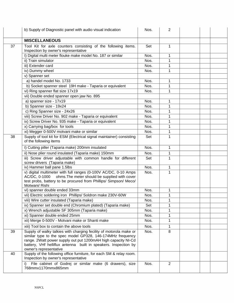
b) Supply of Diagnostic panel with audio visual indication Nos. 2
MISCELLANEOUS Tool Kit for axle counters consisting of the following items. Inspection by owner's representative
Set 1
I) Digital multi meter flouke make model No. 187 or similar Nos. 1 ii) Train simulator Nos. 1 iii) Extender card Nos. 1 iv) Dummy wheel Nos. 1 v) Spanner set a) handel model No. 1733 Nos. 1 b) Socket spanner steel 19H make - Taparia or equivalent Nos. 1 vi) Ring spanner flat size 17x19 Nos. 1 vii) Double ended spanner open jaw No. 895 a) spanner size - 17x19 Nos. 1 b) Spanner size - 19x24 Nos. 1 c) Ring Spanner size - 24x26 Nos. 1 viii) Screw Driver No. 902 make - Taparia or equivalent Nos. 1 ix) Screw Driver No. 935 make - Taparia or equivalent Nos. 1 x) Carrying bag/box for tools Nos. 1
37
xi) Megger 0-500V motvani make or similar Nos. 1 Supply of tool kit for ESM (Electrical signal maintainer) consisting of the following items
Set 1
I) Cutting piller (Taparia make) 200mm insulated Nos. 1 ii) Nose plier round insulated (Taparia make) 150mm Nos. 1 iii) Screw driver adjustable with common handle for different screw drivers (Taparia make)
Set 1
iv) Hammer ball pane 1.5lbs Nos. 1 v) digital multimeter with full ranges (0-100V AC/DC, 0-10 Amps AC/DC, 0-1000 ohms.The meter should be supplied with cover test probs, battery to be procured from Phillips/ Simpson/ Meco/ Motwani/ Rishi
Nos. 1
vi) spanner double ended 33mm Nos. 1 vii) Electric soldering iron Phillips/ Soldron make 230V-60W Nos. 1 viii) Wire cutter insulated (Taparia make) Nos. 1 ix) Spanner set double end (Chromium plated) (Taparia make) Set 1 x) Wrench adjustable SF 305mm (Taparia make) Nos. 1 xi) Spanner double ended 25mm Nos. 1 xii) Merge 0-500V - Motvani make or Shanti make Nos. 1
38
xiii) Tool box to contain the above tools Nos. 1 39 Supply of walky talkies with charging fecility of motorola make or
similar type to the spec model GP328, 146-174MHz frequency range. 2Watt power supply out put 1200mAH high capacity NI-Cd battery, VHf helliflux antenna built in speakers. Inspection by owner's representative
Nos. 8
Supply of the following office furniture, for each SM & relay room. Inspection by owner's representative
40
i) File cabinet of Godrej or similar make (6 drawers), size 768mmx1170mmx865mm
Nos. 2

NSPCL
ii) Office table of size of table top 1220 mm. X 610 mm., height 750mm., With laminated top, with 3 drawers on left hand side and one locker on right hand side. Olive green colour. Godrej/Alwyn/Chandan/Khira makes.
Nos. 2
iii) Airy revolving and tilting working cane chair with arm rests of teak wood, polished black. The chair has plastic caned seat and back on 25 mm round tubular frame. The base is of pressed seat metal. Godrej/Allwyn/Chandan/Khira make. Width 700 mm., Depth 700 mm., Height 870 mm., Adjustable seat height 410 mm. to 520 mm., colour Grey.
Nos. 2
iv) Wooden stool height 2 feet. Nos. 8
v) Plain storage almirah with 4 adjustable shelves size 1980 mm. Height, 915 mm. Width, 485 mm. Depth. Godrej/Allwyn/Chandan/Khira makes.
Nos. 2
(a) Supply of Universal AxleCounter as per RDSO Spec. No.RDSO/SPN/177/2003, each set consisting of the following:
Set 4
(b) Supply of Digital AxleCounter as per RDSO Spec. No.RDSO/SPN/177/2003, each set consisting of the following:
Set 2
(c) High frequency Tx coil & Rx coil = 2 sets, including mounting accessories fastening parts, protective tube etc. (each set of item 42(a) above consists of web mounting type 2 Nos. of transmiter coil and 2 Nos. of receiver coils with minimum 5.5 meter cable). (b) Track side Digital Axle Counter Unit = 2 Nos. (c) 24V, 1000 Ohms 'Q' type relay = 2 Nos., along with relay box duty wired. (d) Clamp with deflector plates and hardware etc = 4 Sets. (e) Reset box = 02 Nos. Insp.RDSO
(d) Installation, testing, Comissioning and field training at site .
41
NOTE: This includes supply of other sundry materials by the contractor required for commissioning of the work and training to the field staff for maximum of three days.
POWER SUPPLY / BATTERIES
a) SMPS based IPS for panel interlocking station in RE area stations confirming to RDSO spec. no. RDSO/SPN/165/2000 with 2V/300AH lead acid low maintenance secondary cell complete (i.e with floats, links ceramic vent plugs, nuts& bolts) as per spec no. IRS-S-88/93. DC-DC converter, spares & maintenance tool kit. This includes supply of auto change over from any of the phases/generator supply.In the Cabin/Block hut/Panel operation room (Note: The charging secondary cells to be done as per instructions of manufacturer while commisioning. Total 55 cells will form the battery bank 110V)
Set 2
b)Extra DC-DC converters (24-32V, 10A-3 nos. & 3-6V, 0.2A - 2Nos.) in each of the end goomty for power supply of EJB and Telephones is required.
42
c)DC-DC converters for block local supply shall be of 12-40V, 5A in place of 0.5A 7 block line shall be 12-40V, 1A in place of 0.5A; charger shall be 20A each in (4+1) scheme against mentioned in Drg. No. SE/SK/CON/168/2000.
NSPCL
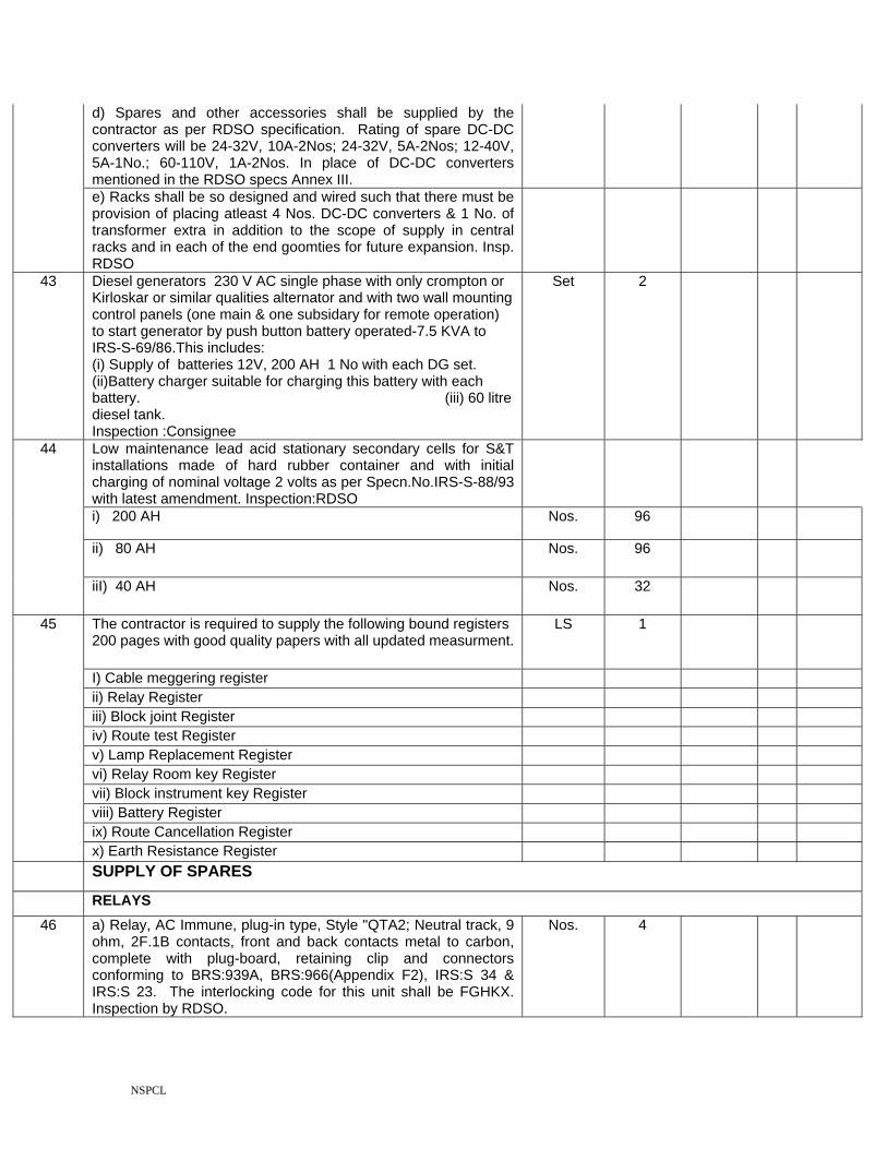
d) Spares and other accessories shall be supplied by the contractor as per RDSO specification. Rating of spare DC-DC converters will be 24-32V, 10A-2Nos; 24-32V, 5A-2Nos; 12-40V, 5A-1No.; 60-110V, 1A-2Nos. In place of DC-DC converters mentioned in the RDSO specs Annex III.
e) Racks shall be so designed and wired such that there must be provision of placing atleast 4 Nos. DC-DC converters & 1 No. of transformer extra in addition to the scope of supply in central racks and in each of the end goomties for future expansion. Insp. RDSO
43 Diesel generators 230 V AC single phase with only crompton or Kirloskar or similar qualities alternator and with two wall mounting control panels (one main & one subsidary for remote operation) to start generator by push button battery operated-7.5 KVA to IRS-S-69/86.This includes: (i) Supply of batteries 12V, 200 AH 1 No with each DG set. (ii)Battery charger suitable for charging this battery with each battery. (iii) 60 litre diesel tank. Inspection :Consignee
Set 2
Low maintenance lead acid stationary secondary cells for S&T installations made of hard rubber container and with initial charging of nominal voltage 2 volts as per Specn.No.IRS-S-88/93 with latest amendment. Inspection:RDSO
i) 200 AH Nos. 96
ii) 80 AH Nos. 96
44
iiI) 40 AH Nos. 32
The contractor is required to supply the following bound registers 200 pages with good quality papers with all updated measurment.
LS 1
I) Cable meggering register ii) Relay Register iii) Block joint Register iv) Route test Register v) Lamp Replacement Register vi) Relay Room key Register vii) Block instrument key Register viii) Battery Register ix) Route Cancellation Register
45
x) Earth Resistance Register SUPPLY OF SPARES
RELAYS 46 a) Relay, AC Immune, plug-in type, Style "QTA2; Neutral track, 9
ohm, 2F.1B contacts, front and back contacts metal to carbon, complete with plug-board, retaining clip and connectors conforming to BRS:939A, BRS:966(Appendix F2), IRS:S 34 & IRS:S 23. The interlocking code for this unit shall be FGHKX. Inspection by RDSO.
Nos. 4

NSPCL
b) Relay, AC Immune, plug-in type, Style 'QSPA1', Neutral line, slow to pickup, 24V DC, 8F, 4B contacts, front and back contacts metal to carbon, complete with plug board, retaining clip and connectors conforming to BRS:933A, IRS:S 60, IRS:S 34 & IRS:S 23. The interlocking code for this unit shall be ABDEJ. Inspection by RDSO.
Nos. 4
c) Relay, AC Immune, plug-in type, Style "QNAI", Neutral line, 24V DC 12F, 4B contracts, front and back contacts metal to carbon with plug board, retaining clip & connectors conforming to BRS:931A, IRS:S 60, IRS:S 34 & IRS:S 23. The interlocking code for this unit shall be ABDFH. Inspection by RDSO.
Nos. 6
d) Relay, AC Immune, plug-in type, Style "QNAI", Neutral line, 24V DC 8F, 8B contracts, front and back contacts metal to carbon with plug board, retaining clip & connectors conforming to BRS:931A, IRS:S 60, IRS:S 34 & IRS:S 23. The interlocking code for this unit shall be ABDGH. Inspection by RDSO.
Nos. 6
e) Relay, plug-in type, Style 'OFF' aspect, A.C.lamp proving relay unit, slow release neutral line relay, metal to carbon, 4F.4B contacts shall be suitable for working in series with the primary winding of colour light signal transformer conforming to IRS:S 59 (110V AC/12V AC) feeding 25/33 watt, double pole, double filament signal lamps conforming to BRS:941A, IRS:S 34 & IRS:S 23. The special interlocking code for this unit shall be CFJKM. Inspection by: RDSO.
Nos. 4
f) Relay, plug-in type, Style 'ON' aspect, A.C.lamp proving relay unit, slow release neutral line relay, metal to carbon, 4F.4B contacts shall be suitable for working in series with the primary winding of colour light signal transformer conforming to IRS:S 59 (110V AC/12V AC) feeding 25/33 watt, double pole, double filament signal lamps conforming to BRS:941A, IRS:S 34 & IRS:S 23. The special interlocking code for this unit shall be CFKMX. Inspection by: RDSO.
Nos. 4
ELECTRIC POINT MACHINE
a) Electric point operating machine IRS type /universal/siemens type(AC immunity 160 V AC) to operate on 110 V DC complete with lock, detector, cable termination box and sliders for lock and detector - rotary locking, universal type as per specification IRS-S-24/2002 with latest amendment, Drg. No.RDSO/S 10800 (for motor). Insp. RDSO.
No. 4 47
b) Ground connection for universal/siemens type point machines (110V DC) complete with insulating materials (5 Rods) as per Drg.No.(i)SA 8805 (ii)RDSO/S/3273 (iii) RDSO/S/3271 (iv) RDSO/S/3267 (v) RDSO/S/3269, Switch extension bracket RDSO/S/3264 & Drive lug S 8806. Inspection by owner representative
Set 4
CABLES
48 Under ground Railway Signalling cable, Unscreened PVC insulated, PVC innersheathed, Armoured and PVC Outer jacket, with high Conductivity annealed copper conductor of size 1.5 sq.mm 1100V electrical grade suiting to Spec. IRS/S/63/89 with latest amendment. Inspection : RDSO
i) Cable 2 core 2.5 sqmm (Copper) signalling cable KM 0.5

NSPCL
ii) 12 Core 1.5 sqmm (Copper) signalling cable KM 0.5
iii) 20 Cores 1.5 sqmm (Copper) signalling cable KM 0.5
iv) 4 quad 0.9mm cable for axle counters KM 0.5
a) Evaluator Universal type analog & Field accessories Set 1
b) High frequency Tx coil & Rx coil = 2 sets, including mounting accessories fastening parts, protective tube etc. (each set of item 42(a) above consists of web mounting type 2 Nos. of transmiter coil and 2 Nos. of receiver coils with minimum 5.5 meter cable). (b) Track side Digital Axle Counter Unit = 2 Nos. (c) 24V, 1000 Ohms 'Q' type relay = 2 Nos., along with relay box duty wired. (d) Clamp with deflector plates and hardware etc = 4 Sets. (e) Reset box = 02 Nos. Insp.RDSO
Set 2
49
c) Electronic junction box 24V Nos. 2
Panel section for Domino type & accessories
a) Track section Nos. 4
b) for point section Nos. 4
c) for 2 aspect signal Nos. 4
50
d) for shunt signal Nos. 4
Push buttons
a) Red Nos. 4
b) Green Nos. 4
51
c) Blue Nos. 4
52 Wire coils 16/02 Coils 50
53 Indoor cable 40 core 0.6 sqmm Mtr 200
54 Indoor cable 60 core 0.6 sqmm Mtr 200
55 Indoor cable 24 core 1 sqmm Mtr 100
Total of Schedule "A"
GENERAL NOTE :-

NSPCL
I) Painting Berger make or Similar and of aproved specification and colouring scheme ( to be advised by the Owner's Engineer ) shall be supplied by the contractor and shall be approved by owner's Engineer before use. Painting includes scrapping and clearing of surface before its use.
ii) Varnish whenever required for carpentary works as per the requirement of the owner shall be supplied by the Contractor.
iii) Sand, cement , 1" inch stone chips and bricks for casting of foundation and for other miscellanous works shall be supplied by the contractor at the site of work.
iv) All meterials which are supplied by the contractor, for the above works are to be inspected by the owner's Engineer/Representative before use.
v) All the residual works, if any including finishing portion must be completed within a period of seven days from the date of commissioning by the contractor.

NSPCL
BILL OF QUANTITIES
SCHEDULE-"B" ERRECTION (SIGNALLING)
S. No.
Description Unit Qty Rate in digits
(In Rs.)
Rate in Words
Total Amount (In Rs.)
Excavation of trench in all soils including soft rocky area and clearing of roots of trees, bushes, rocks etc., ballast and reconditioning etc., (including bailing out water and disposal of extra soil including back filling with excavated earth and ramming of trenches after cable laying for the following depth and width as specified in Technical Circular No:2 of 1988 & correction slip No.S/318/1748 dt. 15.03.2000 issued by CSTE/E.C.Railway. The contractor has to conduct detailed site survey of the cable route. Prepare a plan to get approval of the Railway, putting white lime powder marking before excavation of earth under supervision of railways authorised representative. Wherever several cables of different categories have to be laid in the same path, all cables with brick seperation and in a order confirming to para 2.2.7 of CSTE's Technical Circular No.2 of 1988 shall be laid, instead of seperate trench in the concerned area.
i) Depth 1.2 Mtr. & width 0.5 Mtr. KM 1
1
ii) Depth 1.0 Mtr. & width 0.3 Mtr. KM 5
Excavation of trench in all kinds of soils including softy rocky area and cleaning of roots of trees, bushes, rocks, ballast etc., to a depth of 1 Mtr. & width 0.3M for track/pucca road/ Platform crossing/ level crossing and any other place as advised by the Engineer-in-charge including supply, transportation and laying of RCC pipe with collars (for jointing pipe) 150mm nominal dia to Spec.No:IS-458 in trench and drawing of Signalling/ Power/ Quad cables through pipe including back filling and ramming after cable laying as specified in Technical Circular No.2 of 1988.This include repairing and plastering of platform/pucca road after cable laying. RCC pipe shall be inspected by the owner's representative before laying.
Mtr. 500 2
NOTE:- Power cable, signalling cable, Quad cable as mentioned above, where required, shall be laid in the same trench as signalling cable but in a separate pipe.
3 Cutting and smoothening of inside surface of sizes 80mm deep and 70mm/170mm width for single/multiple cable, chase in concrete or hard rocks or platform/cemented floor. This work includes laying and covering of cable laid in the chase with standard sizes, second class bricks placed and embeded longitudinally for a width of 115mm/230mm for single/multiple cable and plastered as per Drg.No. RE/S&T/ALD/SK/304/85 or any other latest practice adopted by SECR for the following:
(i) Single cable. chase length
in Mtrs.
500
NSPCL
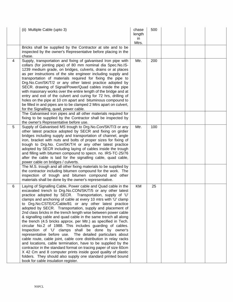
(ii) Multiple Cable (upto 3) chase length
in Mtrs.
500
Bricks shall be supplied by the Contractor at site and to be inspected by the owner's Representative before placing in the chase.
Supply, transportation and fixing of galvanised Iron pipe with collars (for jointing pipe) of 80 mm nominal dia Spec.No.IS-1239 medium grade, on bridges, culverts, drains or at places as per instructions of the site engineer including supply and transportation of materials required for fixing the pipe to Drg.No.Con/SK/T/2 or any other latest practice adopted by SECR. drawing of Signal/Power/Quad cables inside the pipe with masonary works over the entire length of the bridge and at entry and exit of the culvert and curing for 72 hrs, drilling of holes on the pipe at 10 cm apart and bituminous compound to be filled in and pipes are to be clamped 2 Mtrs apart on culvert, for the Signalling, quad, power cable.
Mtr. 200 4
The Galvanised iron pipes and all other materials required for fixing to be supplied by the Contractor shall be inspected by the owner's Representative before use.
Supply of Galvanised MS trough to Drg.No.Con/SK/T/3 or any other latest practice adopted by SECR and fixing on girdier bridges including supply and transportation of channel, angle iron, bracket with nuts and bolts of proper sizes for fixing of trough to Drg.No. Con/SK/T/4 or any other latest practice adopted by SECR including laying of cables inside the trough and filling with bitumen compound to specn. no. IRS-TC-25/76 after the cable is laid for the signalling cable, quad cable, power cable on bridges / culverts.
Mtr. 100 5
The M.S. trough and all other fixing materials to be supplied by the contractor including bitumen compound for the work. The inspection of trough and bitumen compound and other materials shall be done by the owner's representative.
6 Laying of Signalling Cable, Power cable and Quad cable in the excavated trench to Drg.No.CON/SK/T/5 or any other latest practice adopted by SECR. Transportation, supply of 'U' clamps and anchoring of cable at every 10 mtrs with 'U' clamp to Drg.No:CSTE/C/Cable/81 or any other latest practice adopted by SECR. Transportation, supply and placement of 2nd class bricks in the trench length wise between power cable & signalling cable and quad cable in the same trench all along the trench (4.5 bricks approx. per Mtr.) as specified in Tech. circular No.2 of 1988. This includes guarding of cables. Inspection of 'U' clamps shall be done by owner's representative before use. The detailed particulars about cable route, cable joint, cable core distribution in relay racks and locations, cable termination, have to be supplied by the contractor in the standard format on tracing paper of size 60cm X 42 Cm and 8 computer prints inside good quality of plastic folders. They should also supply one standard printed bound book for cable insulation register.
KM 25

NSPCL
NOTE: 1. The cable should not criss-cross inside the trench through-out the length of cable trench. 2) All the materials required for above work including cables and materials included in Sch. 'A' shall be provided by contractor. 3) Cable laying and jointing/termination should go on simultaneously.This includes guarding of cables, relaying of cables and redoing of cable jointing in case of the thefts or otherwise at contractor's own cost for item no. 1 to 6 as mentioned above till commissioned.
7 Transportation of cables in roll with or without wooden drums to work site and meggering before loading and after laying, and recording the values in cable insulation register along with representative or railways.
Drums/ Rolls
50
8 The excavation of pit, casting of concrete foundation including sorrounding earthwork along the foundation, modification of steel apparatus case if required and erection, installation and wiring of steel appartus case to Drg.No. CON/SK/T/8 or any other latest practice adopted by SECR with 4 Nos. of foundation bolts 20mm x 460mm to Drg.No.SA-112 A/M or any other latest practice adopted by SECR with one nut & one washer, fixing of sal wood shelves planks, S.W.strips. Hylum sheet of size 63 mm x 37 mm x 3 mm. for writing terminal description, terminals, fuse blocks, signal transformer, current transformer, filament switching unit, track battery chargers, adjustable/fixed resistances, choke coils, Fuses, relays, E type locks etc. as required, including fixing and termination of cables with number embossed ferrules, wiring, including cable insertion, termination/wiring in associated works in existing apparatus case to draw 110V AC therefrom in the new apparatus case as required at site, testing and commissioning as per approved wiring diagram including subsequent alterations, and bunching of cables with PVC tape, earthing of cable armours etc., as required.
Painting of the apparatus case inside and outside after clearing the surface thoroughly and first coating of anti-corrosive paint and subsequent two coatings of Alluminium paint outside and Red Oxide inside, painting of Sal wood planks and S.W.Strips and lettering etc. This includes transportation of materials. The standard ratio of cement concrete (cement, sand and 1" stone chips) shall be 1:3:6 respectively. This also includes supply of sand and filling up of cable pit inside the apparatus case by sand and fixing of anti-tilting arrangement for shelf type relays if required and advised by Owner's representative.
No. 45

NSPCL
NOTE:- All the materials required for installation, wiring, testing and commissioning of steel apparatus cases as per approved wiring diagrams including subsequent alterations other than signalling Relays, track battery chargers, choke coils and those material as included in material supply schedule 'A' will have to be supplied by the Contractor. These sundry materials such as MS Plates/Angles for anti theft arrangement in theft prone areas, MS Wiring ladders, anchor (foundation) bolts with nuts and washers (4 nos. each), M.S.Clamps with bolts and nuts of sizes for fixing cables, bolts, nuts, screws of sizes for fixing equipment and hylum sheets, sal wood planks/strips required for the above work shall be supplied by the contractor. This includes supply of sand and filling of cable pit inside the apparatus case and other wiring materials like eye-lets of sizes, PVC bunching tapes and buttons, numbered ferrules, condensers and resistances as per the required values, varnish and paints, fevicol, soldering material of approved quality etc., cement, sand, bricks, 1" stone chips etc. by the Contractor.
All the steel apparatus cases should have same ward of 'E' type lock as required by the Railway.
NOTE:- All the sundry materials except that included in Sch.A will be supplied by the contractor.
9 Installation, wiring and testing as per approved wiring diagrams including subsequent alterations, testing and commissioning of Q-series/Composite Relay Racks and cable termination racks (with 3/4" x 9" anchor bolts, with one nut and one washer per bolt), fixing of aluminium ladder as per requirement, modification of Relay rack and C.T.Rs, fixing of plug boards, Relays, terminal blocks, terminals, tag blocks, fuses, bus bars, signal transformers, current transformers, sal wood shelves, sal wood strips/hylum sheets of size 725 mm x 37 mm x 3 mm for writing terminal description etc., fixing and termination of cables on the relay racks, with number embossed ferrules, bunching of cables with PVC tape, earthing of cable armours, covers including painting and lettering, anti-tilting arrangement. This includes filling in of Cable ducts, Cale pits / Masonry enclosures underneath the relay racks and CTRs in Relay rooms, Battery room, Equipment room, Power rooms by sand and plastering the same. The contractor has to bupply fuse analysis chart, location wiring plan, relay position on the tracing paper of size 60cm x 42 cm, including 8 sets of computer
Each rack
24
prints inside good quality of plastic folders, relay registers. Two sets of wiring diagram to be returned with contract Nos. and alterations/modifications as per site indicated in RED therein before commissioning.

NSPCL
Masonry enclosures underneath the racks and CRTs in Relay rooms, Battery room, Equipment room, Power rooms by sand and plastering the same. The contractor has to supply fuse analysis chart, contact analysis chart, terminal analysis chart, location wiring plan, relay position on the tracing paper of size 60 cm X 42 Cm, including 8 sets of computer prints inside good quality of plastic folders, relay registers. Two sets of wiring diagram approved by Railways or Owner's representative to be returned with contact Nos and alterations, modifications as per site indicated in RED therein before commissioning.
NOTE:- All the materials required for the installation, wiring, testing and commissioning of Relay racks as per the approved wiring diagram including subsequent alterations other than signalling Relays and those materials included in material supply (schedule 'A') will have to be supplied by the Contractor. Those sundry materials such as M/s. Plates/Angles, aluminium Wiring ladders, anchor bolts with nuts and washers (4 nos. each), M.S.Clamps with bolts and nuts of sizes for fixing cable, screws of sizes and hulum sheets required for the above work shall be supplied by the contractor. This includes supply of sand and filling of cable pit below the Relay rack and other wiring materials like eye-lets of sizes, PVC bunching tapes and buttons, numbered ferrules, condensers and resistances as per the required values, soldering material of approved quality etc., by the Contractor.
10 Installation of battery rack and fixing of 1.5 inch thick Hard wood shelves on battery racks, fixing of terminal blocks, aluminium wiring ladder with insulated MS strips over the battery rack and upto equipment racks or relay racks with necessary wall cuttin and masonary works alongwith termination of cables including painting and lettering and provision of suitable anticorrosive paints/coating on sal wood shelves for protection of corrosive effects of acid. This includes placing of batteries and connection thereof.
Each 2
NOTE:- All the materials required for the installation, wiring, testing and commissioning of battery racks other than the materials included in material supply schedule 'B' will be supplied by the contractor. The sundry materials such as 11/2" thick salwood planks, nuts and bolts and screws of sizes, MS clamps with nuts 7 bolts for fixing of cables, MS ladder with insulated strips, eye-lets of sizes, PVC bunching tapes and buttons, paints anticorrossive as well as acid proof, cement, sand etc. and other sundry materials for the work will be supplied by the contractor.

NSPCL
11 Erection and wiring of equipment rack as per Drg.No.CON/SK/T/14 or any other latest practice adopted by SECR and fixing of 1" Hard wood planks aluminium ladder with insulated aluminium strips (size 25mm x 25mm x 5mm) over the equipment racks and upto relay racks with necessary wall cutting and masonary works thereon and placing of all power equipment on equipment rack like switches, transformers, voltage stabilisers, transformer rectifier rectifier sets, DC-DC converter on suitable fixed sal wood board; fabrication, supply, installation wiring of 230V AC switchboard, including termination of cables, painting and lettering as required. The contractor has to supply the equipment position in racks and location boxes, layout of equipment on original tracing paper of size 60mm x 42mm with 8 sets of computer prints inside good quality plastic folder and history of the equipment in the standard railway format in a register printed and well bound.
Each 2
NOTE:- All the materials required for installation, wiring, testing and commissioning of equipment racks other than those materials included in material supply, Schedule-B will have to be supplied by the contractor. These sundry materials such as 1" thick salwood planks salwood board, bolts, nuts, washers nd screws of sizes, clamps with nuts and bolts for fixing of cables, Aluminium ladder with insulated strips, eyelets of sizes, PVC bunching tape and buttons, numbered ferrules, paints, welding materials, cement, sand, Hylum sheets etc., and other such sundry materials required for the work shall be supplied by the contractor.
Excavation of earth pit, transportation, placing & fixing of earth electrode with construction of cement encloser to Drg.No.CON/SK/T9A or any other latest practice adopted by SECR and drawal of 6 SWG GI wire to specn.No.S0814 from earth electrode to goomties, relay rooms, apparatuas case, signal unit, cabin, station, L.C.gate pedestals, battery racks, relay racks, CRTs, equipment racks, various S&T equipments, power panel, control panel, lever frame, cable earth, block earth, control earth, signal screens etc. as the case may be including fixing and soldering of copper lugs at both end of the wire, this includes transportation of materials, painting, lettering etc. The contractor has to supply printed bound book for earth resistence test register in the standard railway format
12
NOTE:- All the materials required for the installation, wiring, testing and commissioning of earth electrode other than the materials included in material supply schedule 'A' will have to be supplied by the contractor. The sundry materials such as charcoal, salt, salmoniac, G.I.Wires, eyelets, paints, soldering materials, copper lug with bolts and nuts, bricks, cement, sand etc., and other sundry materials required for the work shall be supplied by the contractor.
Each 37

NSPCL
13(a) Installation, Testing and Commissioning of track circuits on straight portion of track (without involving points and crossings) as per Drg.No:SK/DRG/OL/27 or any other latest practice adopted by SECR and track bonding plan including drilling of 9/32" holes on rails, provision of bounding, block joints (90R/52Kg/60 Kg) with machined fish plate, fixing and painting of track lead junction boxes, fixing of 25 mm nominal dia GI pipe of required length with 9/32" holes at 10 cm. apart for protection of tail cables, insulation of lead wires from rails using heat shrinkable tape, insulation of traction bonds below rails with 3mm thick heat shrinkable tapes, fixing of lead wire suitably with sleepers. Provision of tail Cable termination, fixing of track lead wires, jumper wires, terminals, track charger, adjustable/fixed resistance. choke coil, fuses, battery, track relay etc., and also lettering/numbering of track lead junction boxes, block joints and track circuits. This includes transportation of all materials required for the above installation and dismantling of existing TLJBs, block joints, bonding etc.
Set 20
13(b) Installation, Testing and Commissioning of track circuits involving points and crossings as per Drg.No.SK/DRG/OL/27 or any other latest practice adopted by SECR and track bonding plan including drilling of 9/32" holes on rails, provision of bonding, block joints (90R/52Kg/60 Kg) with machined fish plate, insulation of stretcher bars (leading and following), gauge/crossing tie plate including welding/riveting of angle cleats, split stretcher bards, fixing and painting of track lead junction boxes, fixing of 25mm nominal dia GI pipe of required length with 9/32" holes at 10 cm. apart for protection of tail cables, insulation of lead wires from rails using heat shrinkable tape, insulation of traction bonds below rails with 3mm thick heat shrinkable tapes, fixing of lead wire suitably with sleepers. Provision of tail Cable termination, fixing of track lead wires, jumper wires, terminals, track charger, adjustable/fixed resistance, choke coil, fuses, battery, track relay etc., and also lettering/numbering of track lead junction boxes, block joints and track circuits.
Set 10
This includes transportation of all materials required for the above installation and dismantling of existing TLJBs, block joints, bonding etc.
Note: (i) Required number of machiend fish plates shall be supplied by the contractor & (ii) The stretcher bars (leading and following), the gauge tie plates, the split stretcher bars shall be supplied & provided by the contractor. (iii) The contractor has to supply the polarity chart of track circuit, track bonding diagram on the original tracing paper of size 60cm X 42cm, including 8 sets of computer prints inside good quality of plastic folders, printed bound book for track circuit test register with details filled therein in the standard railway format(iv) All the materials required for installation, wiring, testing and commissioning of track circuits (straight & crossings) other than track relay, track battery chargers, choke coils and those materials included in material supply schedule 'B' will have to be supplied by the contractor. These sundry materials such as MS Angle/flat, nuts and bolts with washers for fixing of TLJBs, angle cleats to Drg.No.22859/T/SE with nuts, bolts & washers, 1" dia.GI Pipe with holes, rivets required

NSPCL
for providing insulation of gauge/crossing tie plates, MS clamps with nuts and bolts for fixing of cables, 8 SWG soft bond wires, flexible wire, channel pins, paints, eye-lets of sizes, PVC bunching tape and buttons, numbered ferrules, heat shrinkable tape, suitable compound for fixing lead wires with PSC/Wooden sleepers/Rails, soldering materials etc. and other sundry materials required for the work shall be supplied by the contractor. (v) The contractor shall carry-out the modification/ alteration of the existing yard layouts at stations and cabins as per the approved S.I. plan.
14 Installation and wiring of - (i) rotary key transmitters on teak wood board enclosed inside a suitable box with front transparent check cover with locking arrangement
Set 6
NOTE:- All the materials required for installation, wiring, testing and commissioning of rotary key transmitter other than those materials included in material supply Schedule-A will have to be supplied by the contractor. These sundry materials such as 1" thick teak wood boards, transparent sheet for box, locking arrangement. 2 nos. of locks for box and 1 No. lock for front transparent sheet of Godrej or similar make and antitling arrangement, nuts, bolts, washers and screws of sizes, paints, eyelets of sizes, PVC pipe of sizes, PVC bunching tape and buttons, numbered ferrules, welding materials, cement, sand, varnish etc., and other such sundry materials required for the work will be supplied by the contractor.
15 a) Installation, wiring as per approved wiring diagram (and subsequent modifications of the panel as per altered wiring diagram to suit the site conditions), testing and commissioning of control panel (operation cum indication panel) complete with termination of cable, painting and lettering as required. Cable termination in MS rack with 1 inch thick Teak wood strips including fabrication thereof as per requirement of the Railway. Fixing of cable with MS clamps, fixing of terminal block, M.S.wiring ladder with insulated M.S. strips from relay room to panel room, painting and lettering, fillingin sand under control panel rest table, cable duct, covering the open space arround the control panel rest table with bricks lining, masonary work and plastering the same with cement required.
Each 2
b) Installation, wiring as per approved wiring diagram (and subsequent modifications of the panel as per altered wiring diagram to suit the site conditions), testing and commissioning of Diagnostic panel (diagnostic panel with audio visual indication) complete with termination of cable, painting and lettering as required. Cable termination in MS rack with 1 inch thick Teak wood strips including fabrication thereof as per requirement of the Railway. Fixing of cable with MS clamps, fixing of terminal block, M.S.wiring ladder with insulated M.S. strips from relay room to diagnostic panel room, painting and lettering.
Each 2

NSPCL
NOTE:- All the materials required for installation, wiring, testing and commissioning of control Panel and diagnostic panel other than those materials included in material supply, schedule-A will be supplied by the contractor. These sundry materials such as M.S. termination rack, M.S. Angle/Flat, M.S. wiring ladder with insulated M.S.strips, salwood planks, bolts, washers and screws of sizes, eyelets of sizes, PVC bunching tape and buttons, numbered ferrules, Hylum sheets, screws, sunmica, welding materials, paints, cement, sand, cable fixing clamps with nuts and bolts etc., other such sundry materials required for the work will be supplied by the contractor.
Installation, wiring, testing and commissioning of Axle Counter Digital/Universal type, this includes fixing of evaluatorin relay rooms or goomties together with termination of cables, fixing of track inductors on rails, fixing of electronic junction box on suitable sal-wood racks in gomties/Apparatus cases with termination of cables, fixing of Last Vehical Verification (L.V.V) boxes and painting and lettering as required. This also includes installation, cable drawing, wiring as per approved wiring diagram and subsequent alterations, testing of re-setting-cum-indication panel of concerned section for last vehicle verification circuit and point zone verification circuit. Necessary insertion / modification on the control/indication panel to be carried out as per site condition as per instruction of Owner's representative
Set 6 16
NOTE: Teak-Wood board, MS angle/flats, PVC/HDPE pipes, nuts and bolts etc., required for the work shall be supplied by the contractor.
17(a) Installation of signal posts for Multiple Aspect Colour Light Signals complete with signal units, bases, lenses, lamps/LED unit, fixing and wiring of signal transformer/current transformers of LED units, ladders & other fittings, excavation of pit, casting of cement concrete foundations with necessary water outlets thereof as specified in the note given below, erection and fixing of complete fittings of the signal/signal post with necessary earthed screen protection arrangement, including drawing of cable through signal posts, termination of cables, wiring, focussing, testing and commissioning, two coat painting and lettering, supply and fixing of speed boards if required for the following:-
i) 2 ASPECT No. 4
ii) 4 ASPECT No. 1
17(b) Fixing of calling-on signals with enameled markers including drawing of cable through the signal post, termination of cables, wiring, fixing of calling-on/shunt signal legend board, lamp/LED unit, two coat painting and lettering, testing and commissioning as required.
No. 1
NSPCL
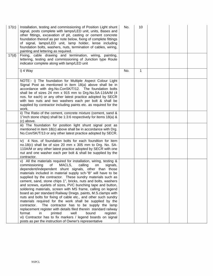
17(c) Installation, testing and commissioning of Position Light shunt signal, posts complete with lamps/LED unit, units, Bases and other fittings, excavation of pit, casting or cement concrete foundation thereof as per note below, fixing of complete fittings of signal, lamps/LED unit, lamp holder, lense including foundation bolts, washers, nuts, termination of cables, wiring, painting and lettering as required.
No. 10
Fixing, cable drawing and termination, wiring, painting, lettering, testing and commissioning of Junction type Route indicator complete along with lamp/LED unit
17(d)
i) 4 Way No. 1
NOTE:- i) The foundation for Multiple Aspect Colour Light Signal Post as mentioned in item 18(a) above shall be in accordance with drg.No.ConSK/T/12. The foundation bolts shall be of sizes 24 mm x 915 mm to Drg.No.SA-116A/M (4 nos. for each) or any other latest practice adopted by SECR with two nuts and two washers each per bolt & shall be supplied by contractor including paints etc. as required for the work.
ii) The Ratio of the cement, concrete mixture (cement, sand & 1"inch stone chips) shall be 1:3:6 respectively for items 18(a) & (c) above.
iii) The foundation for position light shunt signal post as mentioned in item 18(c) above shall be in accordance with Drg. No.Con/SK/T/13 or any other latest practice adopted by SECR.
iv) 4 Nos. of foundation bolts for each foundtion for item no.18(c) shall be of size 20 mm x 305 mm to Drg. No. SA-110A/M or any other latest practice adopted by SECR with one nut and one washer each per bolt & shall be supplied by the contractor.
v) All the materials required for installation, wiring, testing & commissioning of MACLS, calling on signals, dependent/independent shunt signals, other than those materials included in material supply sch-"B" will have to be supplied by the contractor. These sundry materials such as cement, sand, stone chips 1", bricks, nuts and bolts, washers and screws, eyelets of sizes, PVC bunching tape and button, soldering materials, screen with MS frame, calling on legend board as per standard Railway Drwgs. paints, M.S.clamps with nuts and bolts for fixing of cable etc., and other such sundry materials required for the work shall be supplied by the contractor. The contractor has to be supply the lamp replacement register with details filed therein standard railway format in printed well bound register. vi) Contractor has to fix markers / legend boards on signal posts as per the instruction of Owner's representative

NSPCL
Installation of electric point machines on MS plate fixed on wooden/iron/PSC sleepers complete with fixing of anti-theft Belt, crank handle key interlocking arrangement as per the drawing approved by Railways, junction boxes with 11/2" dia G.I.pipe/HDPE pipe of required length up to point machine, ground connections, including smithy works involved, insulation of MS plate on which the point machine is to be fixed from the gauge tie plate, involving revetting/welding of angle, cleats, termination of cables, woring, preliminary adjustment for operation of point by crank handle and susequent final adjustment, painting and lettering as required, testing and commissioned of the same.
Each 21 18
NOTE: All the materials required for installation, wiring, testing and commissioning of electric point machine other than the point machine and those materials included in material supply Schedule_A will have to be supplied by the contractor. These sundry materials such as MS plate/flats/angle cleats, GI/HDPE pipe, bolts and nuts, washers and screws, eyelets of sizes, PVC bunching tape and buttons, numbered ferrules, hylum sheets, welding materials, riverts, MS angle of sizes, Anti theft cover, Cable fixing clamps with nuts & bolts, locks for crank handle interlocking arrangement, paints, cement, sand etc., and other such material as required shall be provided by the contractor. This also includes shifting of detectors and carrying out any other pre NI adjustments as specified by Owner's representative. This also includes supply and transportation of one good quality lock for each Point machine.
19 Installation, cable termination, wiring, testing & commissioning of integrated power supply panel as per approved power supply diagram and specification. The contractor has to supply arrangements at central relay room, goomties on original tracing paper of size 60cm x 42cm with 8 computer prints in the standard railway fromat.
Set 2
20 Installation, cable termination, on the terminals fixed inside the block counter cup board to be made by the contractor as per the advice of the owner's engineer at site. Wiring, painting, lettering, testing and attending to faults therein and commissioning (double line/single line) block working, on block counter cup-board along with fixing of block bell equipment and filter units as per the instructions of the owner's representative at site.
Set 2
NOTE:- All the materials required for installation, wiring, testing and commissioning of TLBI/DLBI/Axle counter block other than those included in material supply Sch-A will have to be supplied by the Contractor. These Sundry materials, such as cup board nuts, bolts and screws of sizes, PVC bunching tape and buttons, numbered ferrules, Hylum sheets, screws, sunmica, welding/Soldering materials, paints, cement, sand, cable fixing clamps with nuts and bolts etc., and other such sundry materials required for the work shall be supplied by the contractor.
21 Supply & Erection alongwith casting of foundation of Stop board /Sighting board/SLB/BSLB/legend board as per aproved drawings. All the material required for the work shall be supplied by the contractor.
Each 4

NSPCL
22 Charging and installation of secondary cell 2 V (lead acid type), and preparation of electrolyte for lead acid cells including supply of sulfuric acid and distilled water for charging the cells for the following:
i) 2 Volt 40 AH Each 32
ii) 2 Volt 80 AH Each 96
iii) 2 Volt 200 AH Each 96
Note: If power is not available at site or work, charging may be done at nearby location as per convenience of the Railway. This includes transportation of uncharged cells at the site of charging, supply of acid and distilled water at the site of charging and transportation of charged cells to the site of work.
23 Testing and commissioning the entire signalling installation and submission of all relevent final 'Asmade' plans of circuit diagrams,Contact analysis chart,termination particulars of apparatus cases and cable termination rack, power supply arrangements, relay index board, cable plans, cable route plans,redboundary plans and all other particulars covered under various schedules. All 'As-mades' shall be prepared in latest version of Auto CAD and submitted in CDs.The negatives shall be made in R.P film to Railway standard size and a company shall be submitted to Owner for approval. On approval of owner's Engineer the contractor shall submit along with the negatives, 8 copies in each, duly making booklet neately bound. Out of 8 sets , 2 sets of drawings and other plans shall be kept in thick plastic cover with hanger arrangements for each cover (2 sheets back to back in one plastic cover ) and handed over to owner.
LS 1
a) Testing and commissioning of entire siganlling installation of the yard
b) Testing and commissioning (LC gate)
24 Design & preparation of Circuits and drawings:- For execution to be made by the contractor as per SECR. Practice in conformity with GR, SR & SEM-1988 Edition provisions and in accordance with CSTE/OL/GRC's circular No.3 of 1984 with the latest alterrations & amendments based on IP (tentative/approved) (to be supplied by the ccontractor & get approval from competent authority indicated by the owner), the contractors is required to design and prepare the following circuits and drawings in Auto CAD including subsequent alterations & submit two Computer Prints for approval of Railway/owner's representative. After the approval party should submit six sets of Computer prints for execution.
Set 1

NSPCL
(1) Route Control chart, (2) Circuit diagrams, (3) Panel front plate diagram, (4) Cable Route plan (5) Cable core chart, (6) Terminal analysis chart, (7) Fuse Analysis chart, (8) Location wiring plan, (9) Cable termination chart in relay room and location box, (10) Equipment position plan, (11) Cable insulation register, (12) Polarity chart of track circuit/track circuit bounding plan, (13) SWR diagram, (14) Power supply arrangement, (15) Track circuit Test register, (16) Battery history register, (17) Earth testing record Register, (18) Relay Register, (19) History of equipment, (20) Block joint/Glued joint register, (21) Contact analysis.
On successful completion of the work the contractor should prepare all the completion drawings and submit in 2 sets of Computer prints within 7 days period and subsequently after approval must submit the original prints on tracing papers. After approval on the original tracking the contractor should submit 8 copies of hard copy/blueprint inside good quality plastic folder (two drawing sheets back to back in One plastic folder) along with 2 sets of Soft Copy backups in floppies & CDs and original approved tracings.
NOTE: 1) After the award of the contract, the contractor shall supply all the drawings in 2 sets, well in advance for approval of Railway/owner's technical representative prior to commencement of the work.
2) Size of the drawings shall be A2 size.
3) Six copies of the approved drawing to be supplied by the contractor for execution of the work within two weeks of approval of drawings by the Railways/owner's technical representative.
4) After commissioning of the work, contractor shall prepare all the completion drawings in 2 sets and put up it to approval of Rlys. Within one week and subsequently after their approval submit the original prints on tracing papers. After approval on the original tracing all drawings in 8 sets of hard copy/blue print along with the original tracing complete in all respects and two sets of soft copies in CDROM to be handed over to the Owner/railways.
5) In course of execution of the work, any future development, additions and alterations etc. also to be incorporated in the circuit.
Total of Schedule "B"

NSPCL
TELE COMMUNICATION ARRANGEMENTS BETWEEN BESCL INPLANT AND BHILAI "P"CABIN BILL OF QUANTITIES
SCHEDULE-"C" SUPPLY ITEMS (TELECOMMUNICATION)
S.No. Description of the item Unit Qty Rate in
digits (In
Rs.)
Rate in Words
Total Amount (In
Rs.) 1 Supply of cable hut equipment 2/34 MB as per the technical
specification & all other stipulations, fully wired for its ultimate capacity, testing & commissioning includes the following items
Set 2
a) 2/34 MB Optical Line Terminating Unit (OLTU) with all accessories inspection by RDSO as per the TC 81-2000
No.s 1
b) Rack for housing of equipment No.s 1
c) Higher order MUX 2/34, Pulse code modulation multiplexing equipment confirms to the ITU(T) recomondation G.703,G.712 & G.732 inspection by RDSO
No.s 1
d) Drop insert MUX No.s 1
e) Terminal MUX No.s 1
f) Surge and lighting equipment No.s 1
g) Fibre distribution frame No.s 1
h) Pig tails No.s 12
i) Maintenance free battery 100 AH No.s 1
j) OFC Termination box No.s 2
k) Aluminium ladder No.s 1
Note: All the required other materials including sockets,rakcs,cords and sundry materials shall be supplied by the contractor
2 Supply of 24 fibre armoured Optical fibre cable confirming to RDSO Specification TC-55-98 manufactured by RDSO approved firms from part-I list and with RDSO inspection
Km 9
3 Supply of straight through jointing kit complete with required material as per the RDSO drawing
Set 12
4 Supply, installation, testing & commissioning as per the technical specification of Cable Hut equipment 2 MB includes the following items
Set 2

NSPCL
a) 2/B OLTE complete with all accers. Nos. 1
b) 2 MB Drop / Insert MUX complete with accers Nos. 1
c) Mounting Rack for OLTE & all accessories Nos. 1
d) Surge protection device Ls 1
e) Maintenance free batteries 120 AH Set 1
f) Switch board and power cable of sorts Ls 1
g) MISC Mounting and fixing arrangement Nos. 1
h) Network monitoring system Ls 1
i) OFC Termination box No.s 1
j) Aluminium ladder Nos. 1
k) Pigtails Nos. 12
Note: All the required other materials including sockets,rakcs,cords and sundry materials shall be supplied by the contractor
5 Supply of 6 Quad Under ground telecom cable 0.9mm dia confirming to RDSO Specification TC-30-96 manufactured by RDSO approved firms from part-I list and with RDSO inspection certificate. The cable shall be supplied in lengths of one Km per drum.
Km 9
6 10 Pair 0.63 mm dia polythene insulated, polythene sheathed jelly filled U/G telephone cable with poly-Al moisture barrier and steel tape armoured. The cable should confirm to RDSO specification No. IRS-TC-41/97 (or latest). The cable should be procured from RDSO approved firms with RDSO inspection and to be delivered at Secunderabad.
Km 2
7 Supply of Head Quarters Equipment for Emergency Control circuit as per RDSO Specification No.IRS-TC-61/93 with line interface to suit for OFC working
Nos 1
8 Supply of DTMF 4 wire based Headquarters Equipment for Control Circuits as per RDSO Spec. No. IRS-TC-60/93(or latest) with power supply unit to suit RDSO Spec. No. IRS.TC.72.97 (or latest)
Nos 1
9 Supply of 4 way VF isolation transformer bay to RDSO Drg.No. TCA - 15201 (or latest): This should have 12 Nos of 470 : 600 ohms impedance VF transformers to RDSO Spec. No.IRS. TC-22-76 (or latest) in two shelves with 4 Nos of U link pannels fully equipped with plugs and wired with protective devices LD and Poly Switches RX 010.
Nos 6
10 WACO annalog Earth tester 4 terminal type - range 0-10 and 0-100 ohms along with test kit and leather case
No 1

NSPCL
11 Supply of thermoshrinkable jointing kit as per Specification TEC201A OL92 with RDSO modifications (for 6Q DC cable) for derivation joint (2T Joint) suiting to 6 quad dry core underground cable of Spec. IRS.TC.30/96 (or latest) and 10 pair P.I.J.F. derivation cable of Spec. IRS.TC.41/97 (or latest). The material to be inspected by RDSO.
Nos 10
12 Supply of Thermoshinkable jointing kit as per Spec. No. TE201 AOL 92 with RDSO modifications (for 6Q DC cable) for Derivation joint without transformer suitable for 6 Quad dry core cable of Spec. IRS.TC.30/96 (or latest) P.I.J.F derivation cable of Spec. IRS.TC.41/97 (or latest). The material to be inspected by RDSO.
i) 5 Pair Mtr 200
ii) 10 Pair Mtr 1000
iii) 20 Pair Mtr 500
13 PVC wire coils of 3/0.75mm size (100 Mts length for each coil) to RDSO Spec. No. IRS.S.76/89 (or latest). Colour as specified by the Engineer-in-Charge.
Coils 20
14 Hand held Digital multimetre with leads, 3 1/2 digit Fluke 19 make. Nos 2
15 Insulation Megger (with digital readout) 500 Volts / 100V - 1000 Meg Ohms range. The megger should be standard make and approved by the Railway Engineer. The required working voltage will be specified by Railway engineer
Nos 1
16 Supply of Battery charger Self Regulating type input 230 V AC - Out put 24V DC 10 Amps. RDSO Spec. No. IRS.S.86/2000 (or latest), for signal application.
Nos 4
17 Supply of Battery charger Self Regulating type Input 230V AC - Out put 12V DC 10 Amps. RDSO Spec. No.IRS.S.86/2000 (or latest), for Telecom Application (for Headquarters equipment).
Nos 4
18 2-T transformer joint assembly 470:1120 as per RDSO Spec. TL-76/2000 (or latest)
Nos. 6
19 Supply of Emergency plug & Socket six pin flat as per RDSO Spec. No. IRS/TC/42/87 (or latest)
Nos 10
20 Desk type 2 wire DTMF 12 way selective calling group telephone, RDSO. Spec.No.IRS/TC/80/2000. (Tentative) (Without Power supply).
Sets 1
21 Power supply for DTMF Equipment / Selective calling telephone to IRS/TC 72/97 (or latest) with 12V 7 AH battery.
Nos 1
22 Supply of emergency socket box (Drg.No.15220 Adv) with socket 6 pin flat (RDSO Spec.No.IRS.TC.42/87-Amt. 1)
Nos 10
NSPCL
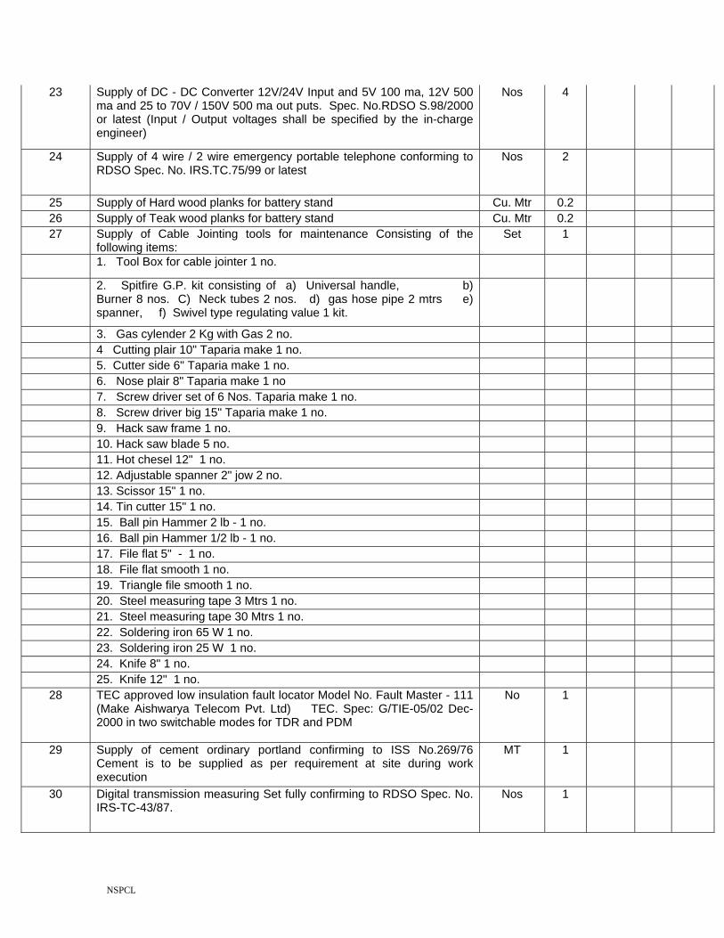
23 Supply of DC - DC Converter 12V/24V Input and 5V 100 ma, 12V 500 ma and 25 to 70V / 150V 500 ma out puts. Spec. No.RDSO S.98/2000 or latest (Input / Output voltages shall be specified by the in-charge engineer)
Nos 4
24 Supply of 4 wire / 2 wire emergency portable telephone conforming to RDSO Spec. No. IRS.TC.75/99 or latest
Nos 2
25 Supply of Hard wood planks for battery stand Cu. Mtr 0.2 26 Supply of Teak wood planks for battery stand Cu. Mtr 0.2 27 Supply of Cable Jointing tools for maintenance Consisting of the
following items: Set 1
1. Tool Box for cable jointer 1 no.
2. Spitfire G.P. kit consisting of a) Universal handle, b) Burner 8 nos. C) Neck tubes 2 nos. d) gas hose pipe 2 mtrs e) spanner, f) Swivel type regulating value 1 kit.
3. Gas cylender 2 Kg with Gas 2 no. 4 Cutting plair 10" Taparia make 1 no. 5. Cutter side 6" Taparia make 1 no. 6. Nose plair 8" Taparia make 1 no 7. Screw driver set of 6 Nos. Taparia make 1 no. 8. Screw driver big 15" Taparia make 1 no. 9. Hack saw frame 1 no. 10. Hack saw blade 5 no. 11. Hot chesel 12" 1 no. 12. Adjustable spanner 2" jow 2 no. 13. Scissor 15" 1 no. 14. Tin cutter 15" 1 no. 15. Ball pin Hammer 2 lb - 1 no. 16. Ball pin Hammer 1/2 lb - 1 no. 17. File flat 5" - 1 no. 18. File flat smooth 1 no. 19. Triangle file smooth 1 no. 20. Steel measuring tape 3 Mtrs 1 no. 21. Steel measuring tape 30 Mtrs 1 no. 22. Soldering iron 65 W 1 no. 23. Soldering iron 25 W 1 no. 24. Knife 8" 1 no. 25. Knife 12" 1 no.
28 TEC approved low insulation fault locator Model No. Fault Master - 111 (Make Aishwarya Telecom Pvt. Ltd) TEC. Spec: G/TIE-05/02 Dec-2000 in two switchable modes for TDR and PDM
No 1
29 Supply of cement ordinary portland confirming to ISS No.269/76 Cement is to be supplied as per requirement at site during work execution
MT 1
30 Digital transmission measuring Set fully confirming to RDSO Spec. No. IRS-TC-43/87.
Nos 1
NSPCL
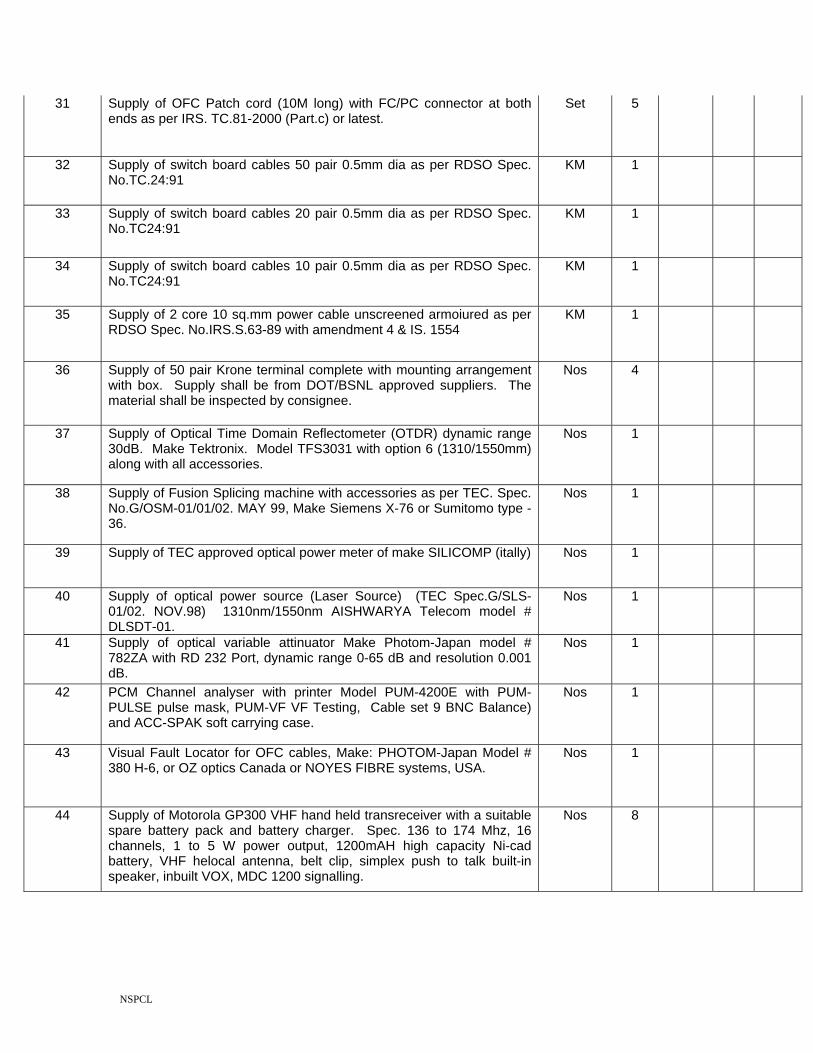
31 Supply of OFC Patch cord (10M long) with FC/PC connector at both ends as per IRS. TC.81-2000 (Part.c) or latest.
Set 5
32 Supply of switch board cables 50 pair 0.5mm dia as per RDSO Spec. No.TC.24:91
KM 1
33 Supply of switch board cables 20 pair 0.5mm dia as per RDSO Spec. No.TC24:91
KM 1
34 Supply of switch board cables 10 pair 0.5mm dia as per RDSO Spec. No.TC24:91
KM 1
35 Supply of 2 core 10 sq.mm power cable unscreened armoiured as per RDSO Spec. No.IRS.S.63-89 with amendment 4 & IS. 1554
KM 1
36 Supply of 50 pair Krone terminal complete with mounting arrangement with box. Supply shall be from DOT/BSNL approved suppliers. The material shall be inspected by consignee.
Nos 4
37 Supply of Optical Time Domain Reflectometer (OTDR) dynamic range 30dB. Make Tektronix. Model TFS3031 with option 6 (1310/1550mm) along with all accessories.
Nos 1
38 Supply of Fusion Splicing machine with accessories as per TEC. Spec. No.G/OSM-01/01/02. MAY 99, Make Siemens X-76 or Sumitomo type -36.
Nos 1
39 Supply of TEC approved optical power meter of make SILICOMP (itally) Nos 1
40 Supply of optical power source (Laser Source) (TEC Spec.G/SLS-01/02. NOV.98) 1310nm/1550nm AISHWARYA Telecom model # DLSDT-01.
Nos 1
41 Supply of optical variable attinuator Make Photom-Japan model # 782ZA with RD 232 Port, dynamic range 0-65 dB and resolution 0.001 dB.
Nos 1
42 PCM Channel analyser with printer Model PUM-4200E with PUM-PULSE pulse mask, PUM-VF VF Testing, Cable set 9 BNC Balance) and ACC-SPAK soft carrying case.
Nos 1
43 Visual Fault Locator for OFC cables, Make: PHOTOM-Japan Model # 380 H-6, or OZ optics Canada or NOYES FIBRE systems, USA.
Nos 1
44 Supply of Motorola GP300 VHF hand held transreceiver with a suitable spare battery pack and battery charger. Spec. 136 to 174 Mhz, 16 channels, 1 to 5 W power output, 1200mAH high capacity Ni-cad battery, VHF helocal antenna, belt clip, simplex push to talk built-in speaker, inbuilt VOX, MDC 1200 signalling.
Nos 8
NSPCL
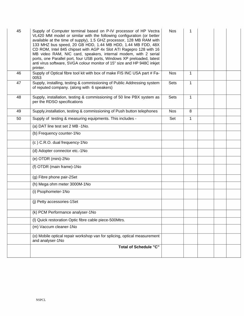
45 Supply of Computer terminal based on P-IV processor of HP Vectra VL420 MM model or similar with the following configuration (or better available at the time of supply), 1.5 GHZ processor, 128 MB RAM with 133 MHZ bus speed, 20 GB HDD, 1.44 MB HDD, 1.44 MB FDD, 48X CD ROM, Intel 845 chipset with AGP 4x Slot ATI Ragepro 128 with 16 MB video RAM, NIC card, speakers, internal modem, with 2 serial ports, one Parallel port, four USB ports, Windows XP preloaded, latest anti virus software, SVGA colour monitor of 15" size and HP 948C inkjet printer.
Nos 1
46 Supply of Optical fibre tool kit with box of make FIS INC USA part # Fa-0053
Nos 1
47 Supply, installing, testing & commissioning of Public Addressing system of reputed company. (along with 6 speakers)
Sets 1
48 Supply, installation, testing & commissioning of 50 line PBX system as per the RDSO specifications
Sets 1
49 Supply,installation, testing & commissioning of Push button telephones Nos 8
50 Supply of testing & measuring equipments. This includes - Set 1
(a) DAT line test set 2 MB -1No.
(b) Frequency counter-1No
(c ) C.R.O. dual frequency-1No
(d) Adopter connector etc.-1No
(e) OTDR (mini)-2No
(f) OTDR (main frame)-1No
(g) Fibre phone pair-2Set
(h) Mega ohm meter 3000M-1No
(i) Psophometer-1No
(j) Petty accessories-1Set
(k) PCM Performance analyser-1No
(l) Quick restoration Optic fibre cable piece-500Mtrs.
(m) Vaccum cleaner-1No
(o) Mobile optical repair workshop van for splicing, optical measurement and analyser-1No
Total of Schedule "C"

NSPCL
TELE COMMUNICATION ARRANGEMENTS BETWEEN BESCL INPLANT AND BHILAI "P"CABIN
BILL OF QUANTITIES SCHEDULE-"D"
ERRECTION(TELECOMMUNICATION)
S.No. Description of the item Unit Qty Rate in
digits (In
Rs.)
Rate in
Words
1 Final location survey of cable route and final preparation of cable route plan as per technical specification
RKM 7
2 Trenching in all types of soil as indicated in sub-items below after cutting of trees and bushes on the marked route by removing the roots of vegitation, refilling and ramming of earth after laying the cable. The trench shall be of 0.35 meters width and one metre depth except in hard rock area where drg.no.RE/S&T/ALD/SK 303/85 or any other latest practice adopted by SECR.
a Ordinary soil Km 3.5
b Hard soil Km 1.5
c Hard rock as per drg.no.RE/S&T/ALD/SK 303/85 or any other latest practice adopted by SECR.
Km 0.5
d Concreting of Cable trench inrocky soil wherever the depth of the trench is possible only between 30 Cm to 50 Cm as per the instructions of the site engineer. The ration of concrete is 1:3:6
Mtr 500

NSPCL
e Supply and laying of fully burnt country bricks (B' Class) of size 220mm x 100mm x 60 mm (Approx.), horizontally breadthwise in the cable trench on the cable laid, without gap as directed by the Railway's representative in station area.
RMT 9000
f Unwinding OF cables from drums duly erecting cable drums on the winches without causing any damage and laying
KM 9
g Unwinding 6 Quard Telecom cables from drums duly erecting cable drums on the winches without causing any damage and laying
KM 9
Note: Loading, unloading & transportation of materials Cable Drums of OFC and 6 Quad Telecom cables to the site of the work shall be carried out by the contractor.
h Jungle cutting along the cable route. Mtr 1500
3 Supply,Concreting & fixing cable marker as per specification. (All materials shall be supplied by the contractor including cement except cable marker)
Nos 400
4 Supply & Laying of GI pipes of 50/100 mm dia with suitable coupling wherever required as per Railway requirement over the Cement bridges, girder bridges, drainage, culverts etc. In case of cement concrete bridges/Culverts, GI pipes are to be provided with brick masonary and in case of Girder bridges, suitable M.S. Clamps to be provided with all fixture and supports and the pipe ends are to be closed with brick masonary. The entire work to be carried out as per technical specification (G.I Pipes shall be supplied by Railways. Remaining all materials are to be arranged by the
RMT 500
5 Supply and laying (in already prepared trench as per technical specification) of Double walled Corrugated Pipe made of High Dencity Polyethilene of size 78mm outer diameter and 63.5 mm inner diameter as per British standard No. BSEN 50086-1and BSEN 50086-2-4.
Mtr 500
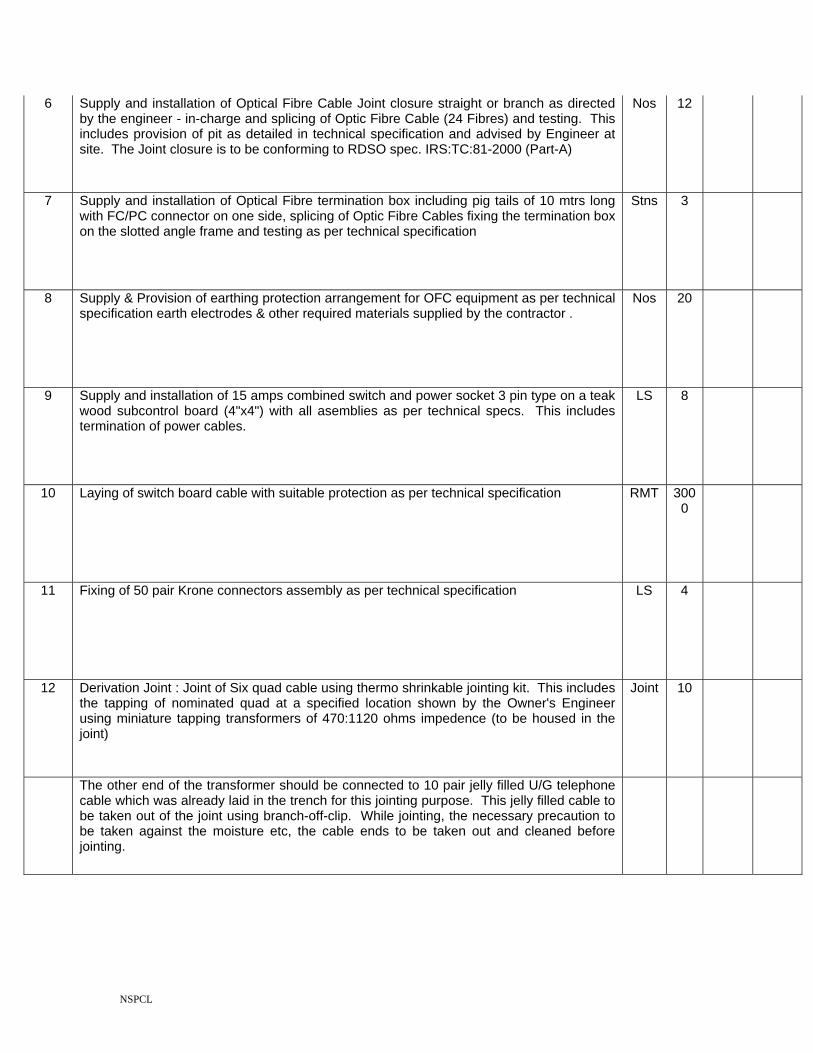
NSPCL
6 Supply and installation of Optical Fibre Cable Joint closure straight or branch as directed by the engineer - in-charge and splicing of Optic Fibre Cable (24 Fibres) and testing. This includes provision of pit as detailed in technical specification and advised by Engineer at site. The Joint closure is to be conforming to RDSO spec. IRS:TC:81-2000 (Part-A)
Nos 12
7 Supply and installation of Optical Fibre termination box including pig tails of 10 mtrs long with FC/PC connector on one side, splicing of Optic Fibre Cables fixing the termination box on the slotted angle frame and testing as per technical specification
Stns 3
8 Supply & Provision of earthing protection arrangement for OFC equipment as per technical specification earth electrodes & other required materials supplied by the contractor .
Nos 20
9 Supply and installation of 15 amps combined switch and power socket 3 pin type on a teak wood subcontrol board (4"x4") with all asemblies as per technical specs. This includes termination of power cables.
LS 8
10 Laying of switch board cable with suitable protection as per technical specification RMT 3000
11 Fixing of 50 pair Krone connectors assembly as per technical specification LS 4
12 Derivation Joint : Joint of Six quad cable using thermo shrinkable jointing kit. This includes the tapping of nominated quad at a specified location shown by the Owner's Engineer using miniature tapping transformers of 470:1120 ohms impedence (to be housed in the joint)
Joint 10
The other end of the transformer should be connected to 10 pair jelly filled U/G telephone cable which was already laid in the trench for this jointing purpose. This jelly filled cable to be taken out of the joint using branch-off-clip. While jointing, the necessary precaution to be taken against the moisture etc, the cable ends to be taken out and cleaned before jointing.

NSPCL
All the materials required for the work are to be arranged by the contractor himself except Thermoshrinkable jointing kit and 2-T transformer which is already covered in supply portion of the schedules. After jointing the cable, thorough test such as insulation test, continuity etc., to be carried out jointly with the Railway Engineer.
If any defect or any damage observed during jointing, the contractor should redo the joint free of cost. (Refer Annexure for instructions of cable jointing).
13 Straight through / derivation with out transformer joints: Installation Thermo shrinkable jointing kits for straight through / derivation joints for LC gate, pump houses etc where VF transformers are not required. This includes tapping of nominated Quad at a specific location shown by the Railway Engineer at site without using transformer to the jelly field cable already laid. All material except thermoshrinkable jointing kit shall be supplied by the contractor. (Refer Annexure for instructions on cable jointing)
Joint 12
14 Fabrication, installation and fixing of emergency socket post, box and Emergency socket as per the Drawing No.OHE/1.6A/94 (enclosed). These emergency socket posts to be fixed along with the cable route at an interval of not more than 1 KM as per the direction and location specified by the Railway Engineer at site. This involves the termination of 10 pair jelly filled cable on the 6 pin emergency socket as per IRS-TC-42/87(or latest) inside the emergency socket box. This post should be concreted at its base and painted with alternative bands of black and white colour. all materials should be supplied by the contractor Rail post & Emergency Sockets. Cutting of Rails to the required size shall be done by the contractor.
Nos 10
15 Supply and fixing of 10 pair CT box and termination of jelly filled cable as per details given by engineer at site for LC gates / Pump house. The CT box after termination shall be sealed by pouring Parafin wax
Nos 10
16 Supply and fixing of 20 pair CT box and termination of jelly filled cable as per details given by engineer at site. The CT box after termination shall be sealed by pouring Parafin wax
Nos 5
17 Testing and commissioning of the 6 quad telecom cable system . This work involves the Testing of Underground four quad cable in each block section after laying and jointing. These readings to be recorded and supplied to Railway Engineer. This involves all the tests to be carried out as detailed in Annexure.
Km 9
18 Installation of battery chargers as advised by the site engineer and wiring of all power supply equipments viz., charges, transformers, batteries, DC-DC Converter etc., Lacing button/thread, copper eyelets for crimping 10 Sq.mm wires are to be supplied by the contractor
Nos 8

NSPCL
19 Supply & Installation and commissioning of 4 Wire way station control equipment as detailed below:
Nos 2
(a) The way station equipment & Power supply unit are to be mounted on a rack as per Drg.No. CORE/S&T/ALD/SK/436/95 and IRS Spec No. TC 82-2005
(b) The internal wiring should be wired between VF Transformer bay and MS Angle rack then to be extended to Dy.SS/ASM Table as per drawing shown in the sketch (All the wiring materials are to be provided by the contractor)
20 Installation of Head Quarters equipment/ Emergency control room equipment at Control office. This includes drawing Switch Board cables from Control office to Test Room and extending Power supply from Test Room to the equipment. All materials except control room equipment shall be supplied by the contractor.
Nos 1
21 Cutting of Masonary walls of other than the cabin building to a depth of .75 mtrs. at places to be indicated by the Engineer and supplying and fixing of 50 mm GI pipes.
Location
4
22 Earthing of transformer bay : Supply and fixing of Earth pipe at Cable hut / Repeater station and other places as advised by Engineer. This includes laying of Earth lead wire and connecting to earth electrode to the transformer bay equipments etc. SOR (Telecom)CORE/ALD or any other latest practice adopted by SECR. All materials to be supplied by the contractor
Nos 2
23 Excavation of coil pit upto a depth of 1 Mtr x 1.5 Mtrs x 1.5 Mtrs for providing Coil at joint location at Culverts, bridges,stations, cable huts and LC gates etc. This includes back filling and ramming of the trench after laying the cable and consolidation of the soil
Nos 5
24 Manufacture, supply and painting of 2 tier battery stand as per tech. Specification. Hard wood plank & all other materials are to be arranged by the contractor.
RMT 15
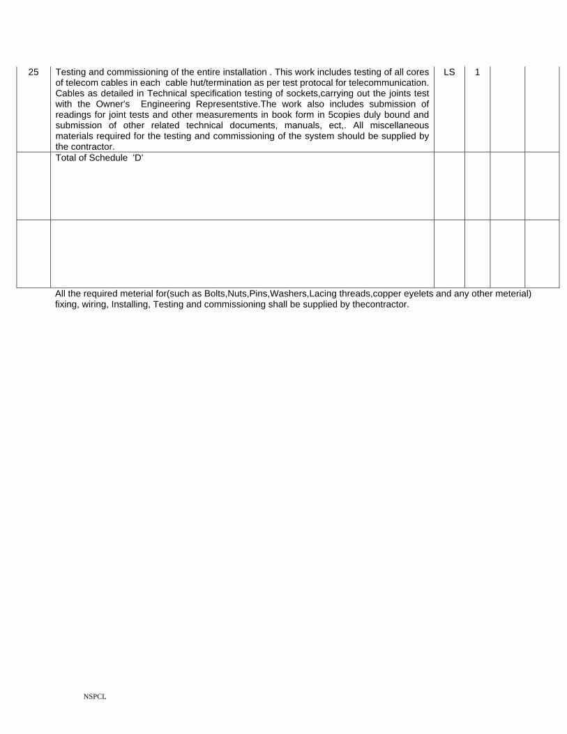
NSPCL
25 Testing and commissioning of the entire installation . This work includes testing of all cores of telecom cables in each cable hut/termination as per test protocal for telecommunication. Cables as detailed in Technical specification testing of sockets,carrying out the joints test with the Owner's Engineering Representstive.The work also includes submission of readings for joint tests and other measurements in book form in 5copies duly bound and submission of other related technical documents, manuals, ect,. All miscellaneous materials required for the testing and commissioning of the system should be supplied by the contractor.
LS 1
Total of Schedule 'D'
All the required meterial for(such as Bolts,Nuts,Pins,Washers,Lacing threads,copper eyelets and any other meterial) fixing, wiring, Installing, Testing and commissioning shall be supplied by thecontractor.