nscf nano-structured cellulose fibers · a paradigm in nanocellulose materials ‐from nanofibers...
TRANSCRIPT

A Paradigm in Nanocellulose Materials ‐ From nanofibers to nanostructured fibers ‐
Hiroyuki Yano
Research Institutes for Sustainable Humanosphere,
Kyoto University
NSCFNano-Structured Cellulose Fibers

Close‐up viewNSCF
Nano‐Structured Cellulose Fibers
150μm
Dissolving pulp (×100)
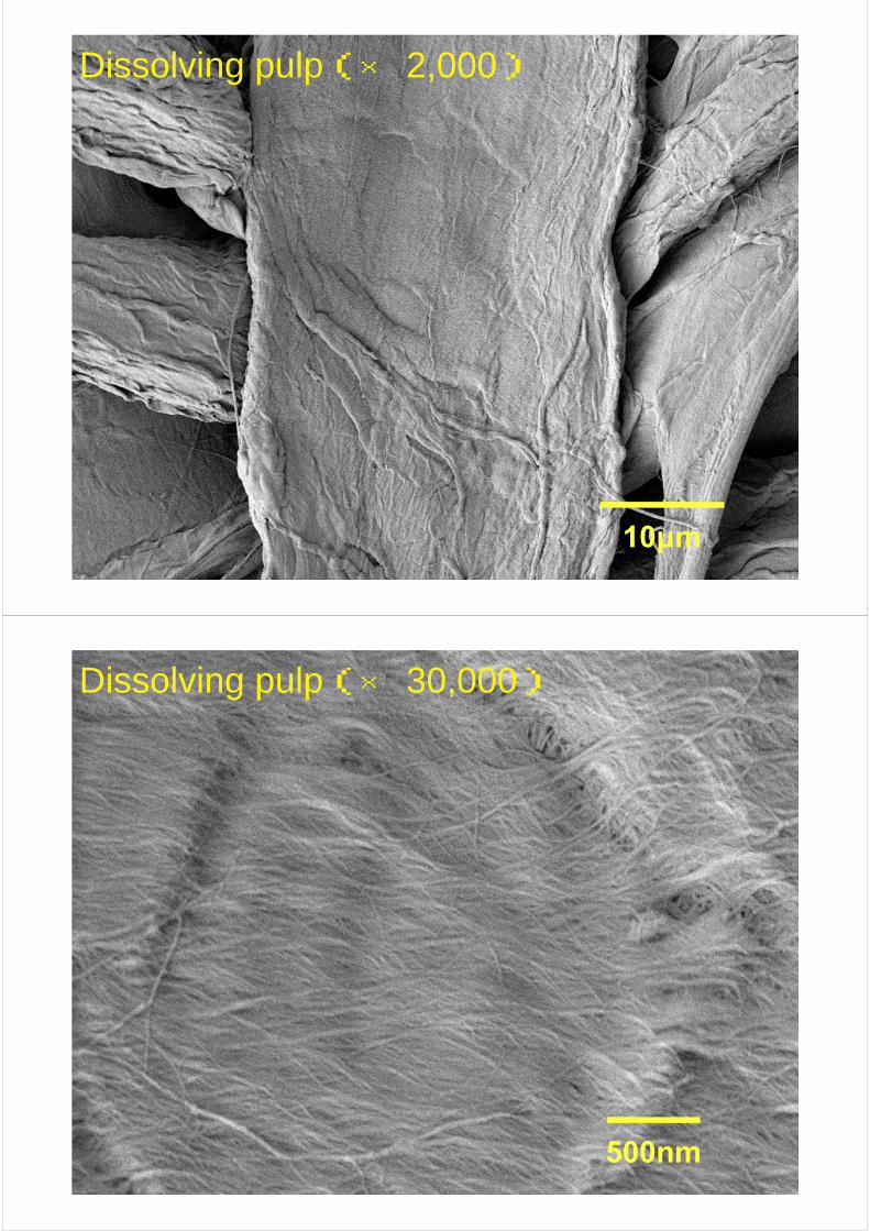
Dissolving pulp(× 2,000)
10μm
Dissolving pulp(× 30,000)
500nm

$0.6-0.8/kg
$20-100/kg
$0.1-0.2/kg
The advantage of pulp: NSCF over CNC , CNF and BC is
“cost”
A Paradigm in Nanocellulose Materials ‐ From nanofibers to nanostructured fibers ‐

Optically transparent nanocellulose
A component less than one‐tenth the size of the optical wavelength can eliminate scattering
Mechanical Reinforcement of Transparent Plastic

Cell Wall Structure
Cell Structure
分子レベル構造
Nano fibers and Matrix
Hierarchical Structure of Wood
10‐50μm
10‐20nm
Microfibrilbundles
Cellulose Nanofibers
Hemicellulose
Lignin
Nano‐Structured Cellulose Fibers
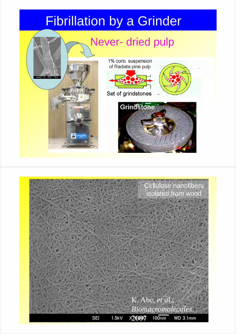
Fibrillation by a Grinder
Never- dried pulp
Cellulose nanofibers isolated from wood
K. Abe, et al., Biomacromolecules, 2007

1% Never-dried Pulp SlurryGrinder treatment
Vacuuming filtration
Acrylic Resin impregnationNanocomposites
Fiber content::5-90 wt%
UV cure
Preparation of Cellulose Nanofiber Composites
・Semi-crystalline extended chains Tensile strength:3GPa → aramid fibers
(Based on D.H. Page, F., El-Hosseiny J. Pulp Paper Sci. 1983)
Young’s modulus:138-141GPa (-200~+200℃)
(T. Nishino et al. J. Polym Sci., Part B, 1995, Proc.2nd Intn'l Cellulose Conf,2007 )
Thermal expansion coefficient:0.1 ppm/K → quartz glass
(T. Nishino, Personal communication, 2004)
High specific surface area
Cellulose Nanofibers:CNF
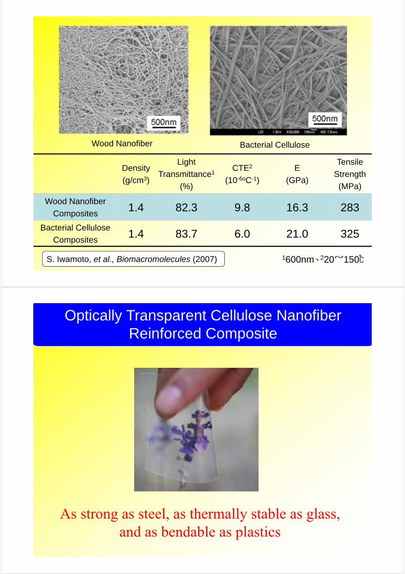
Wood Nanofiber Bacterial Cellulose
Density
(g/cm3)
Light
Transmittance1
(%)
CTE2
(10-6oC-1)
E
(GPa)
Tensile
Strength
(MPa)
Wood Nanofiber
Composites1.4 82.3 9.8 16.3 283
Bacterial Cellulose
Composites1.4 83.7 6.0 21.0 325
1600nm、220~150℃S. Iwamoto, et al., Biomacromolecules (2007)
Optically Transparent Cellulose NanofiberReinforced Composite
As strong as steel, as thermally stable as glass, and as bendable as plastics

Passivation Film
Organic Layers
SiON Barrier Film
Resin (Smoothing Layer)Wood Cellulose Nanocomposites
Anode
Cathode
Device structure
Luminescence of an OLED deposited on the wood nanofiber‐composite
Y. Okahisa, et al., Comp. Sci. Technol. (2009)
A demonstration of production of OLED by R2R process
(GE, USA, Press Release, 13 March, 2008)
A future FPD processing; Continuous “Roll to Roll”
R2R process:simple and inexpensive.
R2R processing enables thecontinuous deposition offunctional materials such assemiconductor, transparentconductive films and gas barrierfilms on a roll of substrate.

2004 2006 2008 2010
BCWood nanofibers
100%Wood nanofibers
Transparent Crab
?
Transparent materials developed in Kyoto Uni.
Schematic presentation of the exoskeleton structure of crustacean shell. (Ifuku, et al. Biomacro, 2009)
Micro to Nano Structure of Crab
Chitin molecule

Crab shell powder, Red king
Deproteinization by NaOH
Demineralization (CaCO3) by HCl
Pigment removal by ethanol
I. Md. Shams and Yano, 2009
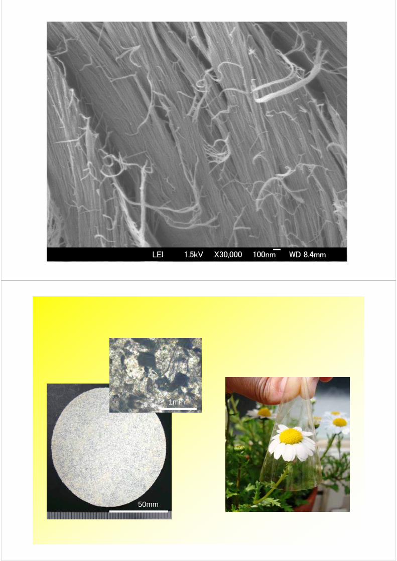
SEM image of chitin particle sheet surface
1 mm x 1mm particle of matrix removed crab shell

SEM image of chitin particle sheet surface
SEM image of chitin particle sheet surface
SEM image of chitin particle sheet surface
50mm
1mm

0
20
40
60
80
100
200 400 600 800
Lig
ht T
rans
mit
tanc
e, %
Wave length, nm
Cellulose nanofibers composites
Chitin powder composites
Acrylic resin
(a) Light transmittance of the chitin powder reinforced acrylic resin sheet(thickness 190 µm, Powder content: 22wt%) and cellulose nanofibers reinforcedacrylic resin sheet (thickness 100 µm and Fiber content: 60wt%).
Comparison of Micro to Nano structures
Crab Wood

The transition from nanofibersto nanostructured fibers
• Encouraged by the transparent crab powdersheet, we undertook the preparation ofoptically transparent pulp-fiber composites.
Slow DewateringSpeed
Low Productivity
Nanofibrillation of Pulp
Difficulty in the production of nanocellulose reinforced composites

Optically transparent pulp sheet
The pulp‐fiber sheet was acetylated, with care taken tomaintain a never‐dried condition, and it was then driedand impregnated with acrylic resin.
Drying
CNF of Never Dried Pulp
ResinImpregnation
Acetylation Acetyl Group
Acetylated Pulp Sheet
Acetylated dry pulp
Never dried Pulp
Resin impregnatedacetylateddry pulp
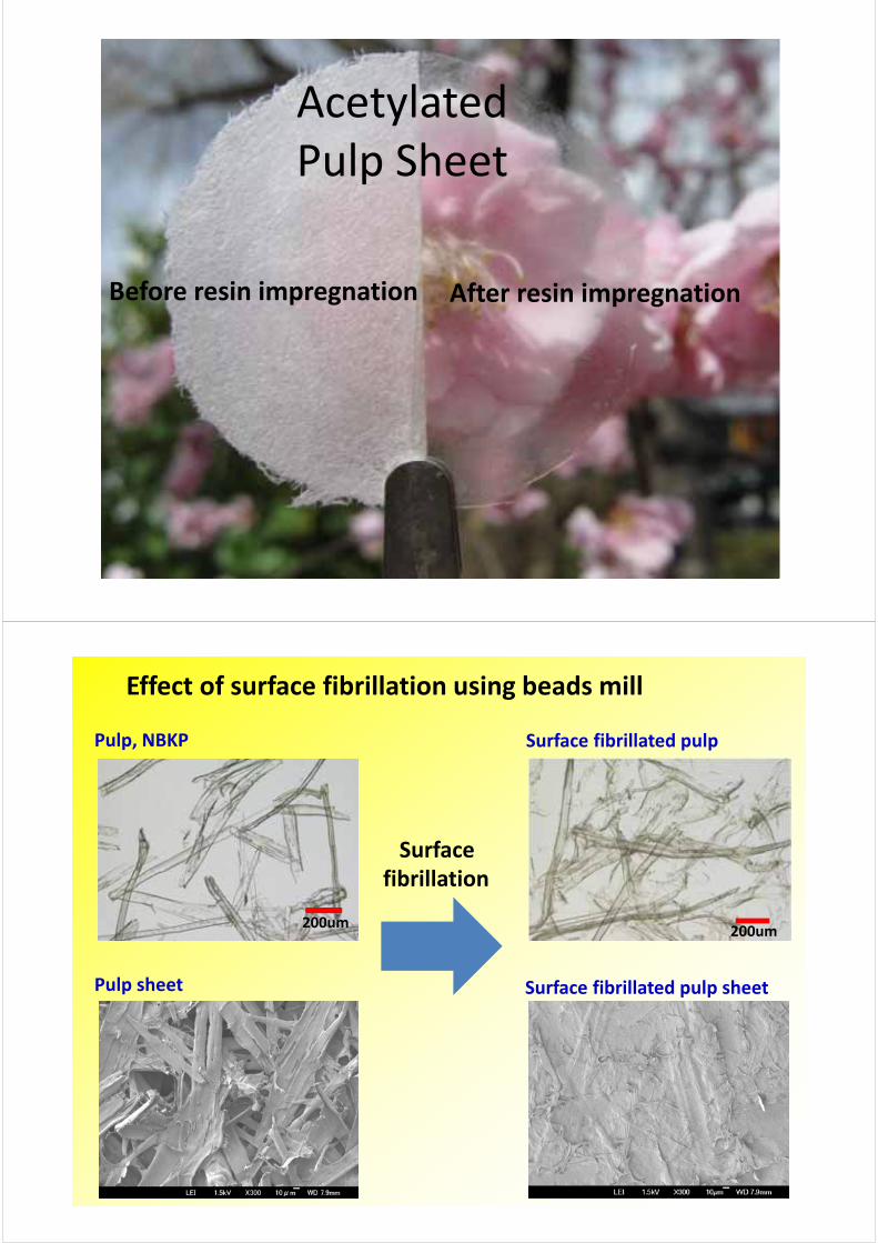
Acetylated Pulp Sheet
After resin impregnationBefore resin impregnation
200um
Effect of surface fibrillation using beads mill
200um
Surface fibrillation
Pulp sheet
Pulp, NBKP Surface fibrillated pulp
Surface fibrillated pulp sheet
0
10
20
30
40
50
60
70
80
90
100
300 500 700
Linear light tran
smittance (%)
Wave length (nm)
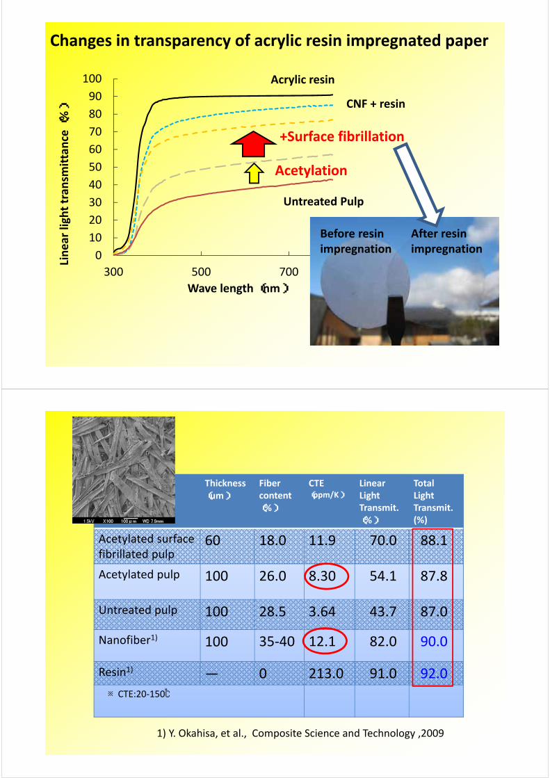
Acrylic resin
+Surface fibrillation
Untreated Pulp
Acetylation
CNF + resin
Changes in transparency of acrylic resin impregnated paper
After resin impregnation
Before resin impregnation
Thickness(um)
Fiber content(%)
CTE(ppm/K)
Linear Light Transmit.(%)
Total Light Transmit. (%)
Acetylated surface fibrillated pulp
60 18.0 11.9 70.0 88.1
Acetylated pulp 100 26.0 8.30 54.1 87.8
Untreated pulp 100 28.5 3.64 43.7 87.0
Nanofiber1) 100 35‐40 12.1 82.0 90.0
Resin1) ― 0 213.0 91.0 92.0※CTE:20‐150℃
1) Y. Okahisa, et al., Composite Science and Technology ,2009

0.6-0.8US$/kg
20-100US$/kg
0.1-0.2US$/kg
The advantage of pulp: NSCF over CNC , CNF and BC is
“cost & performance”
Another example using NSCF
Chemically modified surface fibrillated pulpor Chemically modified NSCF
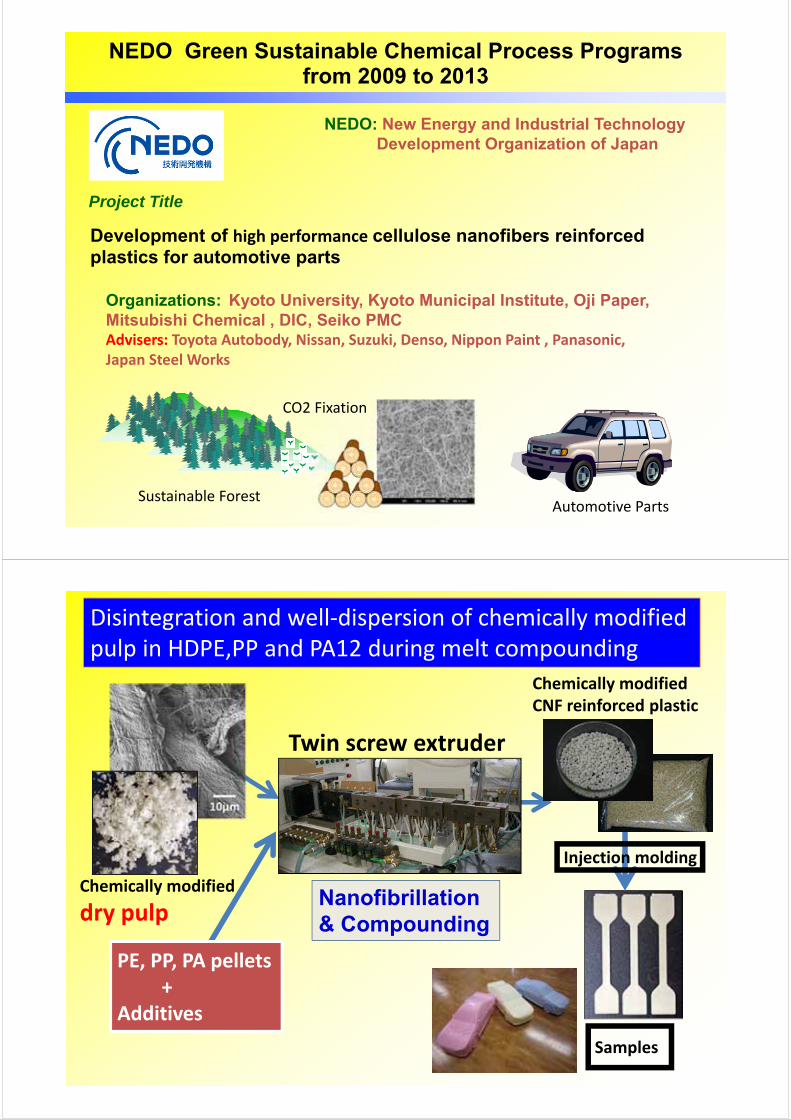
Development of high performance cellulose nanofibers reinforced plastics for automotive parts
Organizations: Kyoto University, Kyoto Municipal Institute, Oji Paper, Mitsubishi Chemical , DIC, Seiko PMCAdvisers: Toyota Autobody, Nissan, Suzuki, Denso, Nippon Paint , Panasonic, Japan Steel Works
NEDO Green Sustainable Chemical Process Programsfrom 2009 to 2013
NEDO: New Energy and Industrial Technology Development Organization of Japan
Project Title
Sustainable ForestAutomotive Parts
CO2 Fixation
Twin screw extruder
Chemically modified
dry pulp
Chemically modified CNF reinforced plastic
Injection molding
Samples
PE, PP, PA pellets+
Additives
Nanofibrillation & Compounding
Disintegration and well‐dispersion of chemically modified pulp in HDPE,PP and PA12 during melt compounding
X‐ray tomography of injection molded samples
+Modified Pulp +Modified CNF
+Unmodified Pulp HDPE
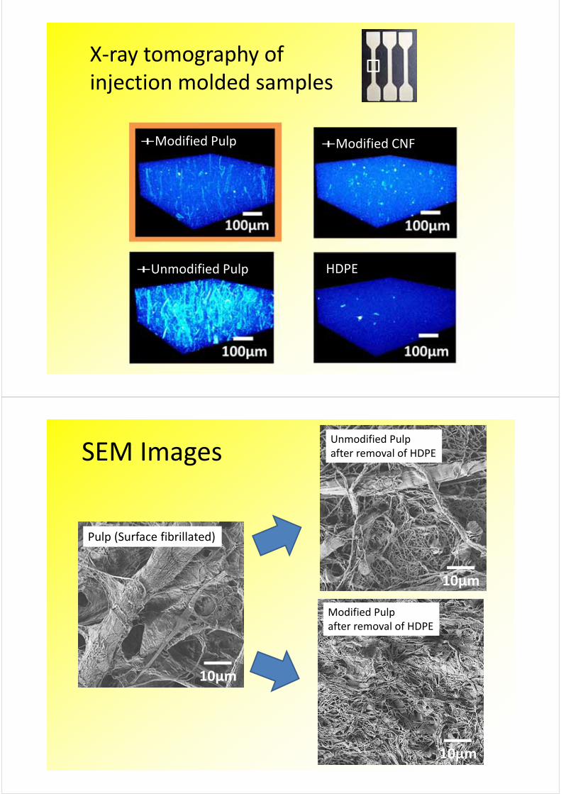
SEM Images
10μm
10μm
Pulp (Surface fibrillated)
Unmodified Pulp after removal of HDPE
10μm
Modified Pulp after removal of HDPE
Stain (%)
Stress (MPa)
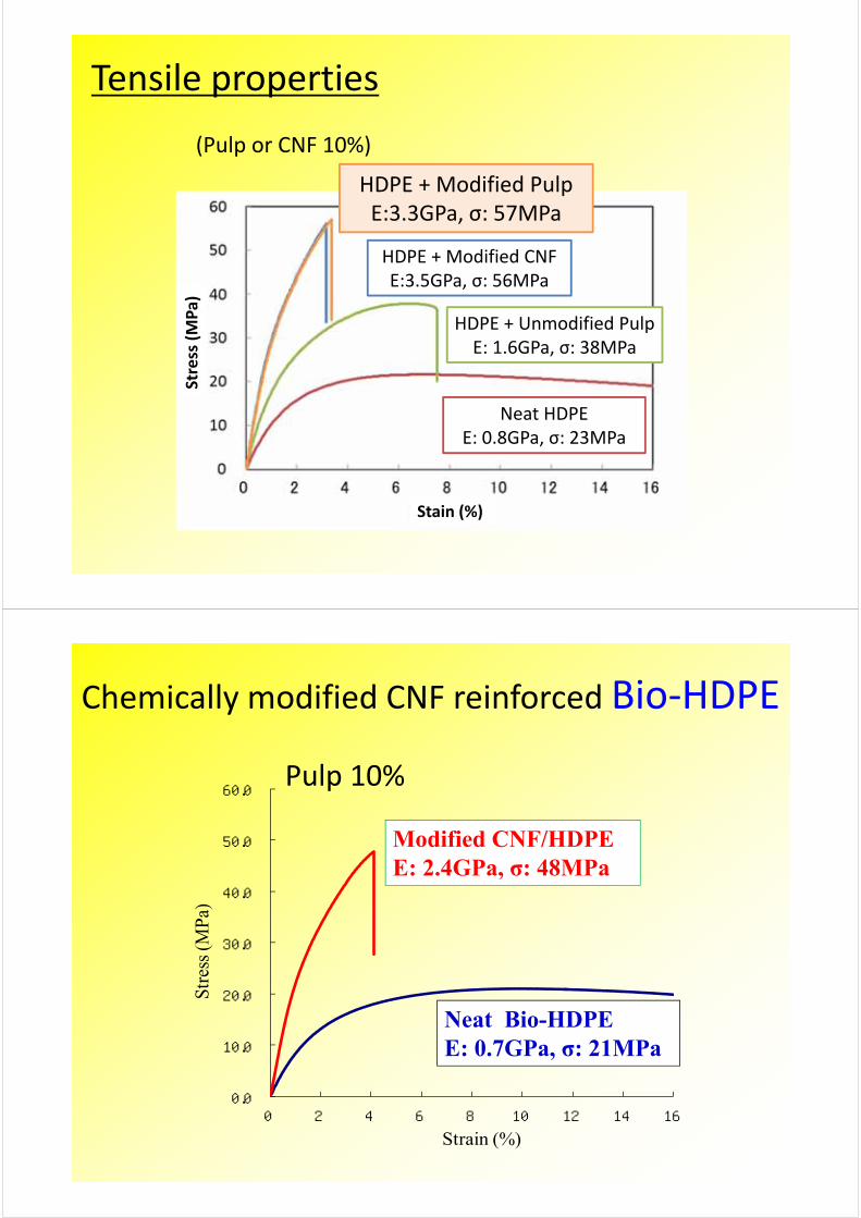
HDPE + Modified PulpE:3.3GPa, σ: 57MPa
(Pulp or CNF 10%)
Tensile properties
HDPE + Unmodified PulpE: 1.6GPa, σ: 38MPa
Neat HDPEE: 0.8GPa, σ: 23MPa
HDPE + Modified CNFE:3.5GPa, σ: 56MPa
0.0
10.0
20.0
30.0
40.0
50.0
60.0
0 2 4 6 8 10 12 14 16
Stre
ss (M
Pa)
Strain (%)
Chemically modified CNF reinforced Bio‐HDPE
Modified CNF/HDPEE: 2.4GPa, σ: 48MPa
Neat Bio-HDPEE: 0.7GPa, σ: 21MPa
Pulp 10%
0
10
20
30
40
50
60
0 2 4 6 8 10 12 14 16
Str
ess
(MP
a)
Strain (%)
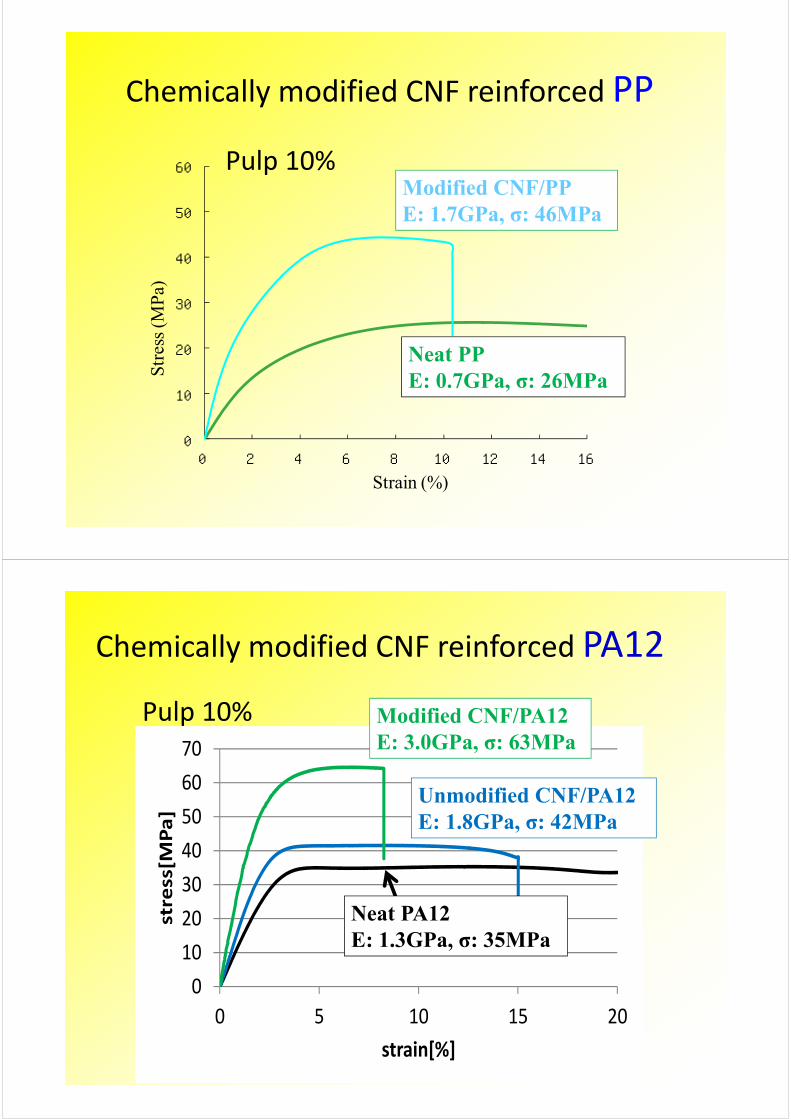
Pulp 10%
Chemically modified CNF reinforced PP
Modified CNF/PPE: 1.7GPa, σ: 46MPa
Neat PPE: 0.7GPa, σ: 26MPa
0
10
20
30
40
50
60
70
0 5 10 15 20
stress[M
Pa]
strain[%]
0
10
20
30
40
50
60
70
0 5 10 15 20
stress[M
Pa]
strain[%]
0
10
20
30
40
50
60
70
0 5 10 15 20
stress[M
Pa]
strain[%]
Unmodified CNF/PA12E: 1.8GPa, σ: 42MPa
Modified CNF/PA12E: 3.0GPa, σ: 63MPa
Neat PA12E: 1.3GPa, σ: 35MPa
Chemically modified CNF reinforced PA12
Pulp 10%
49
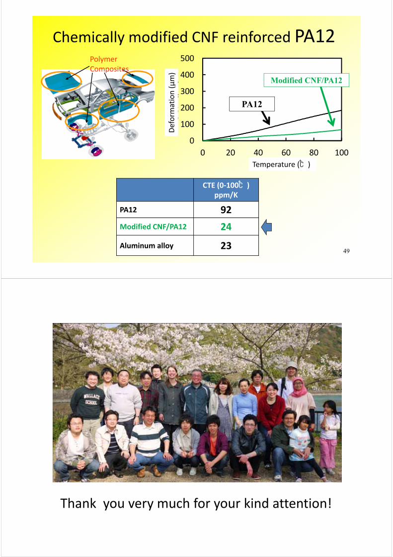
CTE (0‐100℃)ppm/K
PA12 92
Modified CNF/PA12 24
Aluminum alloy 23
0
100
200
300
400
500
0 20 40 60 80 100
変位
(μm)
温度 (℃)
PA12
Modified CNF/PA12
Polymer Composites
Chemically modified CNF reinforced PA12
Temperature (℃)Deform
ation (μm)
Thank you very much for your kind attention!