novel quadrifilar helix antenna combining gnss, … · · 2013-09-08novel quadrifilar helix...
TRANSCRIPT

Novel Quadrifilar Helix Antenna Combining GNSS,
Iridium, and a UHF Communications Monopole P. G. Elliot, E. N. Rosario, R. J. Davis
The MITRE Corporation, Bedford, MA 01730
Abstract- A multi-use antenna system for integrated
communications and navigation capability was developed. A
GPS/GNSS/Iridium antenna is co-located with a UHF
communications monopole on a handset. The
GPS/GNSS/Iridium antenna is a folded Quadrifilar Helix
Antenna (QHA) with novel features to improve frequency
coverage compared to existing QHA designs. This QHA
antenna is co-located concentrically (co-axially) around the
UHF monopole which increases the gain of the UHF monopole
by several dB over most of the UHF 225 – 512 MHz band. Co-
locating the QHA and monopole also reduces the area needed
on the transceiver. The GNSS frequencies covered include
modernized GPS (L1, L2, L5), GLONASS, Galileo, and Beidou
(Compass), spanning from 1164 to 1300 MHz and 1559 to 1611
MHz. The Iridium communications transmit and receive band
(1611-1626 MHz) is also covered, and UHF.
I. INTRODUCTION
This paper describes a multi-use antenna system for integrated communications and navigation (Comm/Nav). This novel (patent pending) antenna combines Global Navigation Satellite System (GNSS) including modernized Global Positioning System (GPS), with Iridium satellite communications, and UHF 225-512 MHz communications.
*
The GPS/GNSS/Iridium antenna is a folded Quadrifilar Helix Antenna (QHA) with novel features which improve frequency coverage compared to existing QHA designs. This QHA antenna is co-located concentrically (co-axially) around a UHF monopole which increases the gain of the monopole by several dB over most of the UHF 225 – 512 MHz communications band. Co-locating the QHA and monopole also reduces the area needed on the transceiver.
The GNSS frequencies covered by the QHA include modernized GPS (L1, L2, L5), GLONASS, Galileo, and Beidou (Compass), spanning from 1164 to 1300 MHz and 1559 to 1611 MHz. The Iridium communications transmit and receive band (1611-1626 MHz) is also covered.
The primary design goal for the QHA was to maximize Right-Hand Circularly Polarized (RHCP) gain at all GNSS frequencies and Iridium at angles from zenith down to 10 degrees above the horizon. A QHA is well suited to this
* This task was supported by USAF GPS Directorate Contract No.
FA8721‐11‐C‐0001 Project No. 03116SC0‐MR.
© MITRE Corp. 2012
application since it provides excellent RHCP coverage at all azimuth and elevation angles, as well as low crosspolarization to reduce multipath.
The antenna patterns and gain are affected by the transceiver handset box upon which the antenna is mounted; for purposes of demonstration, the antennas were optimized and tested on a conductive handset box which is 203mm x 102mm x 38mm (8” long x 4” wide by 1.5” thick); no other ground plane was used. The diameter of the QHAs ranged from 19mm to 38mm (0.75” to 1.5”) so they can fit on top of the handset. A 254mm (10”) long UHF monopole or sleeve was included co-axially through the center of each QHA.
II. FOLDED QHA WITH NOVEL FEATURES
Fig. 1 shows the new folded QHA design and defines some dimensions. The QHA helix traces were made from copper tape placed on a thin Mylar sheet, which is compatible with printed-circuit volume production. The Mylar was then wrapped around a dielectric rod which filled the volume inside the helix. The dielectric is the white material seen inside the helix in the photos; it has an axial hole through the center of the dielectric for the UHF monopole or UHF sleeve monopole.
Fig. 1. Photo of Comm/Nav Folded QHA.

These QHA antennas have four 50-ohm feed points; each feeding one of the four helix driven arms, externally phased in quadrature for RHCP. The QHA also has four folded arms; each folded arm is parallel to the driven helix arm and is shorted at the bottom of the folded arm to the handset conductive case, as seen in Fig. 1.
Use of folded arms for a QHA was previously reported to improve impedance match and bandwidth and/or to reduce size [1]-[6]. Further improvements to the folded QHA were developed under this task to extend the frequency coverage to include all GNSS and Iridium, and also to co-locate it with a UHF monopole.
Fig. 1 shows these novel QHA features. The connections between the driven and folded helix arms in the new QHA design are different from the prior works referenced above. One new feature is the “Series Capacitance” which adds capacitance at the top between each helix driven arm and its respective folded arm. This capacitance was produced by overlapping the copper traces as will be described. Also novel is the “Short to Other Folded Arm” seen at the top of the helix, which connects each helix driven arm to the folded arm of the adjacent helix (not shorted to its own folded arm as in [2]). Integration of the QHA coaxially around a UHF monopole communications antenna is also new, and it was not obvious the QHA would work well with the monopole present until it was tested under this effort.
Tables I and II list dimensions and parameters for each QHA design. The length of the dielectric rod was about 1 mm (0.039”) longer than the QHA Helix Axial Length.
Column e is the Helix Pitch which is the axial length if the helix were extended for 1 full turn (the helix is less than 1 full turn).
Column f is the Helix Pitch Angle defined in Fig. 1 as the slope of helix trace measured from horizontal.
Column g is Degrees of Rotation to Folded Arm shown in Fig. 1; it is the circumferential angle about the center axis of the helix separating the driven helix arm from the folded arm, center to center of the traces.
Column i is the Helix Trace Length in wavelengths; it is the length along each driven arm as it winds around, from the feed point at the bottom, up to the top of the helix, divided by the free-space wavelength at 1.4 GHz, which is the approximate center of the GNSS frequency band .
Column j is the Helix Trace Width of the copper trace used for each helix arm. A trace width as narrow as 0.5 mm (0.020”) was found to improve performance for these folded QHA.
Table I. QHA Prototypes Computer Modeled, Built and Tested.
Dielectric Rod is Rohacell with Relative Permittivity εr =1.07 a. b. c. d. e. f. g. h. i. j.
Prototype Name
QHA Diameter
QHA Helix Axial
Length
UHF Brass
Monopole Diameter
Helix Pitch
Helix Pitch Angle
Degrees Rotation Folded
Arm
Number of turns for each
helix
Helix Trace
Length, wvlgth
Helix Trace Width
Air-loaded 1.5” x 2.9”
38.1mm (1.50”)
74mm (2.913”)
25.4mm (1.00”)
98.3mm (3.870”)
39.2 24 0.753 0.547
o
2mm (0.079”)
Air-loaded 1.0” x 3.2”
24.5mm (1.00”)
81mm (3.189”)
3.2mm (0.125”)
84.8mm (3.338”)
46.4 24 0.955 0.522
o
2mm (0.079”)
Table II. QHA Prototypes Computer Modeled only (not built). Dielectric Rod is EccoStock HiK with Relative Permittivity εr =4.0
a. b. c. d. e. f. g. h. i. j.
Prototype Name
QHA Diameter
QHA Helix Axial
Length
UHF Brass
Monopole Diameter
Helix Pitch
Helix Pitch Angle
Degrees Rotation Folded
Arm
Number of turns for each
helix
Helix Trace
Length, wvlgth
Helix Trace Width
Diel-loaded 1.0” x 2.2”
24.5mm (1.00”)
57mm (2.244”)
3.2mm (0.125”)
78.8mm (3.103”)
44.3 25 0.723 0.381
o
0.5mm (0.020”)
Diel-loaded 0.75”x 2.4”
19.05mm (0.75”)
62mm (2.441”)
3.2mm (0.125”)
66.8 (2.631”)
47.7 30 0.928 0.391
o
0.5mm (0.020”)

III. QHA PROTOTYPE RESULTS
The two QHA in Table I were built and tested. They used a Rohacell foam dielectric material with a very low dielectric constant (εr =1.07) so they are approximately air-loaded.
The QHA antennas were externally phased for RHCP using two quadrature hybrids and one 180 hybrid. The loss through this combiner network is approximately 2 dB, which is incorporated in, and has already reduced, all the measured gains and patterns shown in this paper.
The first QHA in Table I is shown in Fig. 1. This QHA is 38.1 mm wide by 74 mm long (1.5”x2.9”), so it does not exceed the 38.1 mm (1.5”) thickness of the handset case. It encircles a 25.4mm (1”) diameter, 254mm (10”) long metal cylinder such as the novel UHF sleeve monopole in [7]. The bottom of the UHF sleeve is soldered to the handset.
The measured RHCP gain patterns of this QHA are plotted in Figs. 2a through 2d in two cardinal planes. Fig. 3 shows the gain at zenith for all GNSS and Iridium frequencies. The measured zenith gain at L1 is 0.8 dBic and at Iridium it is 0.3 dBic. At L2 and L5 the gain is about -1.4 dBic. Fig. 4 shows the Return Loss (S11) at each input port for this QHA which shows a dual-band very low return loss, which shows a very good impedance match. The measured crosspolarization level for all the QHA was around -20 dBic.
The low-angle coverage of about -5 dBic at 10 elevation is also better than most other types of FRPAs, that is a typical benefit of a QHA type of antenna. This gain performance is good, especially at low elevation angles, considering the presence of the wide diameter UHF sleeve antenna within the QHA. Increasing the diameter of the UHF sleeve still further was found to reduce the gain of the constant width QHA.
The individual port S11 resonances in Fig. 4 do not always occur at exactly the same frequencies as the maximum gain shown in Fig. 3. This is probably mainly due to mutual coupling between the four feed ports of the QHA which will affect the impedance and return loss when all four ports are driven simultaneously for RHCP.
The 2nd
QHA in Table I has the same topology as shown in Fig. 1, but the diameter is less than for the 1
st QHA since
the inserted monopole is much thinner as shown in column d. The 2
nd QHA is 25.4mm (1.0”) wide by 81mm (3.2”) long; it
encircles a thin monopole which is 3.2mm (0.125”) diameter and 254mm (10”) long.
As a result of the thinner monopole, the 2nd
QHA is able to achieve better gain coverage and bandwidth than the 1
st
QHA. The measured RHCP gain patterns of this QHA are plotted in Figs. 5a through 5d. Fig. 6 shows the gain at zenith for all GNSS and Iridium frequencies. The measured peak gain at L1 is 0.8 dBic and at Iridium it is 1.7 dBic. At L2 the gain is 1.4 dBic and at L5 it is 0.8 dBic. Fig. 7 shows the Return Loss (S11) at each input port of this QHA, the return loss is low which is shows a good impedance match. However, it is seen in Figs. 6 and 7 that the best return loss
and gain performance were obtained at a much higher frequency (around 1.75 GHz in Fig. 7), so with additional tuning it would probably be possible to move that high gain resonance closer to the L1 and Iridium frequency.
Patterns were also measured for the 2nd
QHA without any UHF Monopole inserted through it. Those patterns are not shown here due to space limitations, but the QHA performance is similar to the results shown here, and can be reoptimized with a slight re-tuning of the QHA capacitance to compensate for the removal of the monopole.
The 2nd
QHA in Table I above provided much better size - performance tradeoff for GNSS and Iridium than existing folded QHAs described in the literature. The QHA reported in [2] is larger: 34x127mm (1.34”x5.0”), and it does not cover the L5 frequency band. The QHA in [3] covers L1 and L5 frequencies only, not L2 nor Iridium, and the size is 36x72mm (1.42”x2.85”) which is 42% wider than the 1.0”x3.2” prototype in Table I. The QHA in [4] is 36x78mm (1.42”x3.07”) and only covers L1/L2, not L5 nor Iridium. The QHA designs reported in [5] and [6] cover only one narrow frequency band. A prior L1/L2 dual-band trap-loaded QHA [8][9] is about 127mm (5”) long and covers only L1 and L2. It is also not specifically stated in any of these prior papers whether the loss through the quad combiner is included in the reported gain or not. Also, none of these other QHA investigated co-locating a monopole with the QHA.
The performance of the 2nd
QHA was very insensitive to the impedance between the base of the monopole and the handset case: whether open or short circuited or a small gap. So it is not expected that this impedance will have a significant effect on the QHA performance.
Electromagnetic computer modeling software was used to optimize the QHA; specifically High Frequency Structure Simulator (HFSS) with the Distributed Solve Option from Ansys Corporation. The HFSS computed results for the QHA are not included in this paper due to space limitations. The computed patterns are similar to the measured patterns except the computed gain is about 2 to 4 dB higher near zenith than the measured gain. Only 2 dB of that discrepancy is due to quad combiner loss used to form the RHCP for the measurements. The remaining 0 to 2 dB discrepancy is probably due to inaccuracies in the HFSS computer simulation, imperfections in the prototype construction, and measurement tolerances. The HFSS computed S11 curves show a double dip resonance as seen in the measured results in Figs. 4 and 7, although the frequency is often shifted a little in the optimized computed curves, which suggests that further improvements in performance are possible.
The two QHA in Table II were computer modeled but not tested. They have a dielectric material with εr =4. The computer models predicted coverage of GNSS and Iridium frequencies, with or without the thin UHF monopole. Due to the dielectric loading (εr=4.0) the bandwidth is narrower and coverage at L5 is lower gain than the larger air-loaded QHA results shown above. Other dielectric constants as high as 9

and 15 were also tried, but better results were obtained using the lower dielectric constants for these wideband designs
IV. SERIES CAPACITANCE
As shown in Fig. 1, a novel feature is the “Series Capacitance” added between each helix driven arm and it’s respective folded arm, which was found to provide wider bandwidth coverage than a conventional QHA design. This capacitance was produced by overlapping two copper traces, separated by Mylar polyester film to form a small parallel-plate capacitor. This was found to be a more reliable and repeatable method to include very small capacitances in the prototypes than soldering surface-mount capacitors by hand. It also allowed the capacitance to be trimmed to tune the impedance match and to maximize the gain of the antenna at the desired frequencies. The same capacitance was used for each of the four helixes of the QHA. The desired capacitance was first estimated using HFSS modeling, and then it was adjusted empirically by trimming the capacitor overlap length in the prototypes. A typical capacitance for each of the four arms of the QHA was 0.4 pF including fringing effects [11], although it differed somewhat for each QHA design. This capacitance was not fully optimized in the prototypes due to time limitations, so it is possible that additional lab work could improve the results.
V. UHF MONOPOLE
The performance of monopoles is well documented [10][7]. To examine the effect of the QHA on thin UHF monopole performance, a 3.2mm (0.125”) diameter vertical monopole was computer modeled using HFSS on the handset with and without the QHA. Fig. 8 and 9 show the computed monopole gain at the horizon. No earth or human body was included in the simulation. It is seen that the presence of the QHA increases the monopole gain by several dB towards the horizon for most of the UHF communications band. This is due to improved impedance match for the UHF monopole. The isolation between the UHF monopole and QHA ports was computed to be about -45 dB at GNSS frequencies.
ACKNOWLEDGMENT
This task was supported by USAF GPS Directorate. We also thank Dr. Keith McDonald, Janet Werth, and Dr. Basrur Rama-Rao of MITRE for task management, technical recommendations, and review of this paper.
REFERENCES
1. A. Sharaiha, Y. Letestu, and J.C. Louvigne, “Broadband Helical Antenna,” French Patent PCT/FR03/02774, 2002.
2. Letestu, Y., A. Shariha; “Broadband Folded Printed Quadrifilar Helix Antenna”; IEEE Transactions on Antennas & Propagation, Vol. AP-54, n.5. May 2006, pp. 1600-1604.
3. Rabemanantsoa and Sharaiha, “Size Reduced Multi-Band Printed Quadrifilar Helical Antenna”, IEEE Transactions on Antennas and Propagation v.59, n9, pp.3138-3143. Sept 2011.
4. Rabemanantsoa, J., A. Shariha; “Small-folded, Printed Quadrifilar Helix Antenna for GPS Applications”; 14th International Symposium on Antenna Technology and Applied Electromagnetics (ANTEM) and the American Electromagnetics Conference (AMEREM), 2010.
5. Bhandari, B., S. Gao, and T. Brown; “Meandered Variable Pitch Angle Printed Quadrifilar Helix Antenna”; 2009 Loughborough
Antenna and Propagation Conference, 16-17 Nov. 2009. Loughborough, UK.
6. A. Petros and S. Licul, “Folded Quadrifilar Helix Antenna,” in IEEE Antennas and Propagation Symposium, v.4., 2001, pp.569-572.
7. Rama-Rao, B. et.al; “Ferrite Loaded UHF Sleeve Monopole Integrated with a GPS Patch Antenna for a Handset”. Accepted for publication in “Microwave and Optical Technology Letters”, 2012.
8. Lamensdorf, D., Smolinski, “Dual-band quadrifilar Helix Antenna”; IEEE Antennas and Propagation Symposium 2002. v3, pp.488 – 491.
9. Lamensdorf D., M. Smolensk; “Dual Band Quadrifilar Helix Antenna” U.S. Patent # 6653987 Nov. 2003.
10. Chen, To Tai, “Dipoles and Monopoles” in “Antenna Engineering Handbook”, Second Edition; Editors: R.C. Johnson, H. Jasik; McGraw-Hill Book Co. 1984, Chapter 4.
11. http://chemandy.com/calculators/rectangular-capacitor-calculator.htm
FIGURES
Fig. 2a. 1.176 GHz Measured RHCP Gain patterns for Air-loaded
1.5”x2.9” QHA Encircling 25.4mm (1.0”) diam Metal Cylinder on Handset
Fig. 2b. 1.227 GHz Measured RHCP Gain patterns for Air-loaded
1.5”x2.9” QHA Encircling 25.4mm (1.0”) diam Metal Cylinder on Handset
0345
330
315
300
285
270
255
240
225
210
195180
165
150
135
120
105
90
75
60
45
30
15
-30 -20 -10 0dB
Far-field amplitude of dsph11280a2.nsi
RHCP LHCP RHCP 90 LHCP 90
0345
330
315
300
285
270
255
240
225
210
195180
165
150
135
120
105
90
75
60
45
30
15
-30 -20 -10 0dB
Far-field amplitude of dsph11280a2.nsi
RHCP LHCP RHCP 90 LHCP 90

Fig. 2c. 1.575 GHz Measured RHCP Gain patterns for Air-loaded
1.5”x2.9” QHA Encircling 25.4mm (1.0”) diam Metal Cylinder on Handset
Fig. 2d. 1.626 GHz Measured RHCP Gain patterns for Air-loaded 1.5”x2.9” QHA Encircling 25.4mm (1.0”) diam Metal Cylinder on Handset
Fig. 3. Measured RHCP Gain near Zenith for Air-loaded
1.5”x2.9” QHA Encircling 25.4mm (1.0”) diam Metal Cylinder on Handset
Fig. 4. Measured Return Loss Snn at each Input Port of Air-loaded 1.5”x2.9” QHA Encircling 25.4mm (1.0”) diam Metal Cylinder on Handset
Fig. 5a. 1.176 GHz Measured RHCP Gain patterns for Air-loaded
1.0”x3.2” QHA Encircling a 3.2mm (0.125”) diam Monopole on Handset
Fig. 5b. 1.227 GHz Measured RHCP Gain patterns for Air-loaded
1.0”x3.2” QHA Encircling a 3.2mm (0.125”) diam Monopole on Handset
0345
330
315
300
285
270
255
240
225
210
195180
165
150
135
120
105
90
75
60
45
30
15
-30 -20 -10 0dB
Far-field amplitude of dsph11280a2.nsi
RHCP LHCP RHCP 90 LHCP 90
-3
-2
-1
0
1
1.1 1.3 1.5 1.7
Frequency, GHz
Gai
n in
dB
ic
Measured Gain Near Zenith for GNSS Folded QHA Coaxially Surrounding a 1-inch Diameter Brass Sleeve UHF Monopole, and having Novel QHA Capacitive Top-Loading. Mounted on Handheld Metal Case.
0345
330
315
300
285
270
255
240
225
210
195180
165
150
135
120
105
90
75
60
45
30
15
-30 -20 -10 0dB
Far-field amplitude of dsph11320a8.nsi
RHCP LHCP RHCP 90 LHCP 90
0345
330
315
300
285
270
255
240
225
210
195180
165
150
135
120
105
90
75
60
45
30
15
-30 -20 -10 0dB
Far-field amplitude of dsph11320a8.nsi
RHCP LHCP RHCP 90 LHCP 90
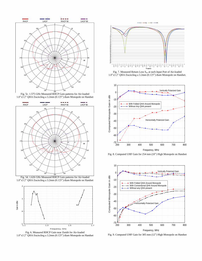
Fig. 5c. 1.575 GHz Measured RHCP Gain patterns for Air-loaded
1.0”x3.2” QHA Encircling a 3.2mm (0.125”) diam Monopole on Handset
Fig. 5d. 1.626 GHz Measured RHCP Gain patterns for Air-loaded
1.0”x3.2” QHA Encircling a 3.2mm (0.125”) diam Monopole on Handset
Fig. 6. Measured RHCP Gain near Zenith for Air-loaded
1.0”x3.2” QHA Encircling a 3.2mm (0.125”) diam Monopole on Handset
Fig. 7. Measured Return Loss Snn at each Input Port of Air-loaded
1.0”x3.2” QHA Encircling a 3.2mm (0.125”) diam Monopole on Handset.
Fig. 8. Computed UHF Gain for 254 mm (10”) High Monopole on Handset
Fig. 9. Computed UHF Gain for 305 mm (12”) High Monopole on Handset
0345
330
315
300
285
270
255
240
225
210
195180
165
150
135
120
105
90
75
60
45
30
15
-30 -20 -10 0dB
Far-field amplitude of dsph11320a8.nsi
RHCP LHCP RHCP 90 LHCP 90
0345
330
315
300
285
270
255
240
225
210
195180
165
150
135
120
105
90
75
60
45
30
15
-30 -20 -10 0dB
Far-field amplitude of dsph11320a8.nsi
RHCP LHCP RHCP 90 LHCP 90
-1
0
1
2
1.1 1.3 1.5 1.7
Frequency, GHz
Gai
n in
dB
ic
Measured Gain Near Zenith for QFHA on HandsetWithout any Monopole
-70
-60
-50
-40
-30
-20
-10
0
10
200 300 400 500 600 700 800
With Folded QHA Around MonopoleWithout Any QHA present
Horizontally Polarized Gain
Vertically Polarized Gain
Frequency, MHz
Co
mp
ute
d M
on
opo
le G
ain
in
dB
i
Gain at Horizon of Thin Monopole with and without QHA. Monopole is 10-inches High and Mounted Vertically on a Handset.
Computed using HFSS. No Earth or Human Body Included.
-70
-60
-50
-40
-30
-20
-10
0
10
200 300 400 500 600 700 800
With Folded QHA Around MonopoleWith Conventional QHA Around MonopoleWithout any QHA present
Horizontally Polarized Gain
Vertically Polarized Gain
Frequency, MHz
Com
pu
ted
Mo
no
po
le G
ain
in
dB
i
Computed Gain at Horizon of Thin 12" Monopole with and without QHA. Mounted Vertically on a Handset.