quadrifilar helix antenna for enhanced air-to … · quadrifilar helix antenna for enhanced air ......
TRANSCRIPT

ARL-TR-7679 ● MAY 2016
US Army Research Laboratory
Quadrifilar Helix Antenna for Enhanced Air-to-Ground Communications
by Steven D Keller, William O Coburn, Theodore K Anthony, and Seth A McCormick Approved for public release; distribution unlimited.

NOTICES
Disclaimers
The findings in this report are not to be construed as an official Department of the Army position unless so designated by other authorized documents.
Citation of manufacturer’s or trade names does not constitute an official endorsement or approval of the use thereof.
Destroy this report when it is no longer needed. Do not return it to the originator.

ARL-TR-7679 ● MAY 2016
US Army Research Laboratory
Quadrifilar Helix Antenna for Enhanced Air-to-Ground Communications
by Steven D Keller, William O Coburn, Theodore K Anthony, and Seth A McCormick Sensors and Electron Devices Directorate, ARL Approved for public release; distribution unlimited.
ii
REPORT DOCUMENTATION PAGE Form Approved OMB No. 0704-0188
Public reporting burden for this collection of information is estimated to average 1 hour per response, including the time for reviewing instructions, searching existing data sources, gathering and maintaining the data needed, and completing and reviewing the collection information. Send comments regarding this burden estimate or any other aspect of this collection of information, including suggestions for reducing the burden, to Department of Defense, Washington Headquarters Services, Directorate for Information Operations and Reports (0704-0188), 1215 Jefferson Davis Highway, Suite 1204, Arlington, VA 22202-4302. Respondents should be aware that notwithstanding any other provision of law, no person shall be subject to any penalty for failing to comply with a collection of information if it does not display a currently valid OMB control number. PLEASE DO NOT RETURN YOUR FORM TO THE ABOVE ADDRESS.
1. REPORT DATE (DD-MM-YYYY)
May 2016 2. REPORT TYPE
Final 3. DATES COVERED (From - To)
09/2014–09/2015 4. TITLE AND SUBTITLE
Quadrifilar Helix Antenna for Enhanced Air-to-Ground Communications 5a. CONTRACT NUMBER
5b. GRANT NUMBER
5c. PROGRAM ELEMENT NUMBER
6. AUTHOR(S)
Steven D Keller, William O Coburn, Theodore K Anthony, and Seth A McCormick
5d. PROJECT NUMBER
TPA # CE-SE-2014-09 5e. TASK NUMBER
5f. WORK UNIT NUMBER
7. PERFORMING ORGANIZATION NAME(S) AND ADDRESS(ES)
US Army Research Laboratory ATTN: RDRL-SER-M 2800 Powder Mill Road Adelphi, MD 20783-1138
8. PERFORMING ORGANIZATION REPORT NUMBER
ARL-TR-7679
9. SPONSORING/MONITORING AGENCY NAME(S) AND ADDRESS(ES)
10. SPONSOR/MONITOR'S ACRONYM(S)
11. SPONSOR/MONITOR'S REPORT NUMBER(S)
12. DISTRIBUTION/AVAILABILITY STATEMENT
Approved for public release; distribution unlimited.
13. SUPPLEMENTARY NOTES
14. ABSTRACT
A self-phased quadrifilar helix antenna is designed, simulated, fabricated and measured for use in Army air-to-ground and airborne-assisted ground-to-ground communication systems. The effect of the metallic ground plane provided by the aircraft fuselage is explored through simulation, and the ideal standoff distance from this ground plane to maximize realized gain is determined. The inclusion of radio frequency (RF) absorber material to shield the antenna from the metallic ground plane is also explored. Prototype antenna measurements are presented and compared with simulation results. The antenna operates very well over the intended TW-400 RF band, with a realized gain of ~4 to 4.5 dBiC and functional beamwidth of ~90° to 110°.
15. SUBJECT TERMS
Antenna, quadrifilar helix, communication, RF
16. SECURITY CLASSIFICATION OF: 17. LIMITATION OF ABSTRACT
UU
18. NUMBER OF PAGES
34
19a. NAME OF RESPONSIBLE PERSON
Steven D Keller a. REPORT
Unclassified b. ABSTRACT
Unclassified c. THIS PAGE
Unclassified 19b. TELEPHONE NUMBER (Include area code)
919-280-6670 Standard Form 298 (Rev. 8/98) Prescribed by ANSI Std. Z39.18

Approved for public release; distribution unlimited. iii
Contents
List of Figures iv
1. Introduction 1
2. Design 2
3. Simulation 3
4. Measurement 13
5. Conclusion 23
6. References 25
Distribution List 26

Approved for public release; distribution unlimited. iv
List of Figures
Fig. 1 Antenna choices for air-to-ground communications link ......................2
Fig. 2 Self-phased quadrifilar helix antenna ....................................................2
Fig. 3 Feed layout for self-phased quadrifilar helix antenna ............................3
Fig. 4 FEKO models of self-phased quadrifilar helix antenna (QHA) as standalone unit, mounted over ground plane, and mounted over absorber-covered ground plane ..............................................................4
Fig. 5 Effect of ground plane and absorber on QHA reflection coefficient .....4
Fig. 6 Effect of ground plane and absorber on QHA radiation pattern and realized gain at 1.7825 GHz...................................................................5
Fig. 7 Effect of ground plane and absorber on QHA axial ratio at 1.7825 GHz ........................................................................................................5
Fig. 8 FEKO models of self-phased quadrifilar helix antenna (QHA) over 6x6" ground plane with absorber and 12x12" ground plane with 6x6" absorber ..................................................................................................6
Fig. 9 Effect of ground plane size on QHA reflection coefficient ...................6
Fig. 10 Effect of ground plane size on QHA radiation pattern and realized gain at 1.7825 GHz .......................................................................................7
Fig. 11 Effect of ground plane size on QHA axial ratio at 1.7825 GHz ............7
Fig. 12 FEKO model of self-phased quadrifilar helix antenna (QHA) over 6x6" ground plane and absorber with variable height above ground plane .......................................................................................................8
Fig. 13 Effect of antenna spacing above ground plane on QHA reflection coefficient ..............................................................................................8
Fig. 14 Effect of antenna spacing above ground plane on QHA radiation pattern and realized gain at 1.7825 GHz ................................................8
Fig. 15 Effect of antenna spacing above ground plane on QHA axial ratio at 1.7825 GHz ............................................................................................9
Fig. 16 Final self-phased quadrifilar helix antenna ..........................................10
Fig. 17 Reflection coefficient for final QHA design ........................................10
Fig. 18 Radiation pattern and realized gain for final QHA design ..................11
Fig. 19 Axial Ratio for final QHA design ........................................................11
Fig. 20 FEKO model of nested quadrifilar helix antenna ................................12
Fig. 21 Simulated reflection coefficient for nested QHA ................................12
Fig. 22 Simulated realized gain for nested QHA .............................................12
Fig. 23 Simulated axial ratio for nested QHA ..................................................13

Approved for public release; distribution unlimited. v
Fig. 24 Fabrication of QHA prototype .............................................................14
Fig. 25 Measured reflection coefficient for QHA ............................................14
Fig. 26 Comparison of simulated and measured reflection coefficient for QHA over 6x6" mounting plate with absorber ..............................................15
Fig. 27 Zoomed comparison of simulated and measured reflection coefficient for QHA over 6x6" mounting plate with absorber ..............................15
Fig. 28 Measured realized gain for QHA .........................................................16
Fig. 29 Comparison of simulated and measured realized gain for QHA .........16
Fig. 30 Measured axial ratio for QHA over 6x6" mounting plate with absorber ................................................................................................17
Fig. 31 Measured axial ratio for QHA over 6x6" mounting plate without absorber ................................................................................................17
Fig. 32 Measured axial ratio for QHA over 12x12" mounting plate with absorber ................................................................................................18
Fig. 33 Comparison of simulated and measured axial ratio for QHA at 1.765 GHz ......................................................................................................18
Fig. 34 Comparison of simulated and measured axial ratio for QHA at 1.7825 GHz ......................................................................................................18
Fig. 35 Comparison of simulated and measured axial ratio for QHA at 1.805 GHz ......................................................................................................19
Fig. 36 Measured radiation pattern for QHA over 6x6" mounting plate with absorber ................................................................................................20
Fig. 37 Measured radiation pattern for QHA over 12x12" mounting plate with absorber ................................................................................................20
Fig. 38 Comparison of simulated and measured radiation pattern for QHA over 6x6" mounting plate with absorber at 1.765 GHz .......................21
Fig. 39 Comparison of simulated and measured radiation pattern for QHA over 6x6" mounting plate with absorber at 1.7825 GHz .....................21
Fig. 40 Comparison of simulated and measured radiation pattern for QHA over 6x6" mounting plate with absorber at 1.805 GHz .......................22
Fig. 41 Comparison of simulated and measured radiation pattern for QHA over 12x12" mounting plate with absorber at 1.765 GHz ...................22
Fig. 42 Comparison of simulated and measured radiation pattern for QHA over 12x12" mounting plate with absorber at 1.7825 GHz .................23
Fig. 43 Comparison of simulated and measured radiation pattern for QHA over 12x12" mounting plate with absorber at 1.805 GHz ...................23

Approved for public release; distribution unlimited. vi
INTENTIONALLY LEFT BLANK.

Approved for public release; distribution unlimited. 1
1. Introduction
Communications systems for Army air-to-ground channels and airborne-assisted ground-to-ground relays are often hindered by polarization losses between the airborne antenna and the terrestrial antenna. For terrestrial communications via a handheld radio, the linear (vertical) polarized whip or flexible stub antenna is traditionally used for its simplicity, ruggedness, and size. For airborne platforms that provide hemispherical coverage to a terrestrial region, typical antennas include bent monopole and blade antennas, which also exhibit linear (vertical) polarization. Significant radio frequency (RF) losses of over 20 dB can occur due to polarization misalignment when the terrestrial radio antenna is tilted off-axis to the vertical position, or when the aircraft in the communications link banks in a “racetrack” flight path in order to provide radio coverage to a desired terrestrial region. In order to ensure a stable communications link, it is critical that these polarization losses be minimized. One method for ensuring this is to replace the vertically polarized antenna on the airborne platform with a low-profile circularly polarized antenna, as shown in Fig. 1. The uniform 3 dB polarization losses that will occur at all tilt angles due to the vertical-to-circular polarization link can be compensated for in the rest of the communication system design much more easily than the intermittent >20 dB polarization losses that might occur in the vertical-to-vertical polarization link.
A quadrifilar helix antenna1–3 (QHA) is an excellent candidate antenna for the airborne link in such a system, providing hemispherical coverage of ~ 100°, 5 dBi realized gain and adequate bandwidth of ~3–4%. For this report, a compact, self-phased quadrifilar helix antenna4 will be designed, simulated, fabricated, and measured. The effect of the metallic ground plane provided by the aircraft fuselage will be explored through simulation, and the ideal standoff distance from this ground plane to ensure maximum realized gain will be determined. The inclusion of RF absorber material to shield the antenna from the metallic ground plane will also be explored. The simulation results for this design will be compared with measured prototype data.

Approved for public release; distribution unlimited. 2
Fig. 1 Antenna choices for air-to-ground communications link
2. Design
The quadrifilar antenna, as shown in Fig. 2, is composed of 2 equally spaced λ/2 long bifilar helical loops, each fed 180° out of phase in order to produce currents along the loops that are in phase quadrature (0, 90, 180, 270°).
Fig. 2 Self-phased quadrifilar helix antenna
In order to achieve a single-input, self-phased quadrifilar helix, one helical loop was designed to be electrically longer compared to a multiple of λ/4, producing an inductive input impedance with +45° phase angle, and the other helical loop was designed to be electrically shorter compared to a multiple of λ/4, producing a capacitive input impedance with –45° phase angle. This results in a relative current phase of 90° between the 2 helices. The antenna may be fabricated using metal wires for the helical legs and a semi-rigid coaxial cable as the input and inner structural support. A SubMiniature version A (SMA) feed is connected at one end of the semi-rigid coaxial cable, and all 4 helical legs are connected to the outer conductor of the semi-rigid coaxial cable at its bottom end. At the top end, complementary legs of each helix are connected as a pair to either the inner or outer
Approved for public release; distribution unlimited. 3
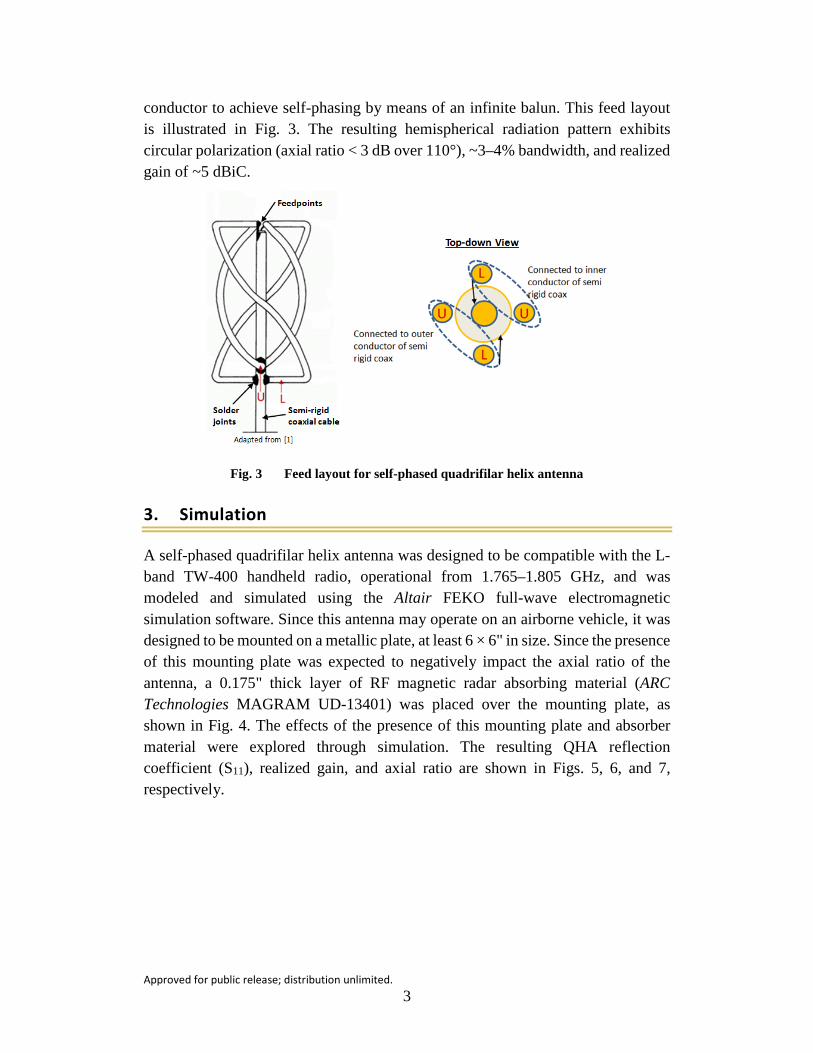
conductor to achieve self-phasing by means of an infinite balun. This feed layout is illustrated in Fig. 3. The resulting hemispherical radiation pattern exhibits circular polarization (axial ratio < 3 dB over 110°), ~3–4% bandwidth, and realized gain of ~5 dBiC.
Fig. 3 Feed layout for self-phased quadrifilar helix antenna
3. Simulation
A self-phased quadrifilar helix antenna was designed to be compatible with the L-band TW-400 handheld radio, operational from 1.765–1.805 GHz, and was modeled and simulated using the Altair FEKO full-wave electromagnetic simulation software. Since this antenna may operate on an airborne vehicle, it was designed to be mounted on a metallic plate, at least 6 × 6" in size. Since the presence of this mounting plate was expected to negatively impact the axial ratio of the antenna, a 0.175" thick layer of RF magnetic radar absorbing material (ARC Technologies MAGRAM UD-13401) was placed over the mounting plate, as shown in Fig. 4. The effects of the presence of this mounting plate and absorber material were explored through simulation. The resulting QHA reflection coefficient (S11), realized gain, and axial ratio are shown in Figs. 5, 6, and 7, respectively.

Approved for public release; distribution unlimited. 4
Fig. 4 FEKO models of self-phased quadrifilar helix antenna (QHA) as standalone unit, mounted over ground plane, and mounted over absorber-covered ground plane
Fig. 5 Effect of ground plane and absorber on QHA reflection coefficient

Approved for public release; distribution unlimited. 5
Fig. 6 Effect of ground plane and absorber on QHA radiation pattern and realized gain at 1.7825 GHz
Fig. 7 Effect of ground plane and absorber on QHA axial ratio at 1.7825 GHz
The realized gain and axial ratio comparisons were made at the middle of the operational band—1.7825 GHz. The reflection coefficient, S11 < –10 dB bandwidth, and realized gain are all marginally affected by presence of ground plane and absorber, with the center frequency shifting by down by less than 1% and realized gain decreasing by ~0.5 dB in the presence of the ground plane. The presence of the RF absorber over the ground plane mitigates this loss. The axial ratio (AR) increases significantly when the ground plane is introduced. For a typical communications system, the axial ratio should be kept under 3.0 dB in order to minimize polarization losses. As a standalone antenna, the QHA has an axial ratio beamwidth of ~100°. In the presence of the ground plane, the axial ratio is greater than 3.0 dB at all angles, making the polarization loss much too high for practical use. Placing the RF absorber over the ground plane restores the axial ratio to under 3.0 dB for a beamwidth approximately equal to its free-space value of 100°.

Approved for public release; distribution unlimited. 6
Since the absorber material is relatively heavy—~1 lb for a 6 × 6 × 0.175" slab—the effect of an increased metallic plate size great than 6 × 6" (e.g., extended section of metallic aircraft frame) on the QHA antenna performance was explored, with the absorber material coverage area kept constant at 6 × 6", as shown in Fig. 8. The effect of an increased ground plane size on the QHA reflection coefficient (S11), realized gain, and axial ratio is shown in Figs. 9, 10, and 11, respectively.
Fig. 8 FEKO models of self-phased quadrifilar helix antenna (QHA) over 6x6" ground plane with absorber and 12x12" ground plane with 6x6" absorber
Fig. 9 Effect of ground plane size on QHA reflection coefficient

Approved for public release; distribution unlimited. 7
Fig. 10 Effect of ground plane size on QHA radiation pattern and realized gain at 1.7825 GHz
Fig. 11 Effect of ground plane size on QHA axial ratio at 1.7825 GHz
The realized gain and axial ratio comparisons were made at the middle of the operational band—1.7825 GHz. The reflection coefficient, S11 < –10 dB bandwidth, and realized gain all remain relatively unchanged, as the size of the ground plane is increased from 6 × 6" to 12 × 12" and the absorber is held constant at 6 × 6". The axial ratio increases moderately at broadside as the ground plane size is increased, ~1 dB higher between –20° and +20°, and the axial ratio beamwidth (AR < 3.0 dB) decreases from 100° to 85°.
Another variable that affects the RF performance of the QHA is its distance above the ground plane and absorber. This spacing variable, labeled ‘s’ in Fig. 12, was varied from λ/16 to λ/2 to explore its influence on the antenna and to find an optimal value, where λ is the operational wavelength of the antenna. The effect of the

Approved for public release; distribution unlimited. 8
QHA’s height above ground plane on the antenna reflection coefficient (S11), realized gain, and axial ratio is shown in Figs. 13, 14, and 15, respectively.
Fig. 12 FEKO model of self-phased quadrifilar helix antenna (QHA) over 6x6" ground plane and absorber with variable height above ground plane
Fig. 13 Effect of antenna spacing above ground plane on QHA reflection coefficient
Fig. 14 Effect of antenna spacing above ground plane on QHA radiation pattern and realized gain at 1.7825 GHz

Approved for public release; distribution unlimited. 9
Fig. 15 Effect of antenna spacing above ground plane on QHA axial ratio at 1.7825 GHz
The realized gain and axial ratio comparisons were made at the middle of the operational band, at 1.7825 GHz. The reflection coefficient improves moderately as the height above the ground plane increased, with the S11 < –10 dB bandwidth narrowing by ~2–3% as the spacing increased from λ/16 to λ/8. A peak realized gain of ~5.3 dBiC is achieved with λ/4 spacing. At λ/16 spacing, the realized gain was ~1 dB less than this peak value, and at λ/2 spacing, the realized gain was ~0.5 dB less. The axial ratio beamwidth (AR < 3.0 dB) was marginally affected by the QHA spacing above the ground plane, with a minor broadening of the beamwidth for the ideal λ/4 spacing. The axial ratio increased by ~0.5 to 1.5 dB with λ/2 spacing.
After conducting these simulation studies on the QHA antenna and the effects of the mounting plate and absorber material, an optimal QHA design was determined to optimize the realized gain and axial ratio < 3.0 dB beamwidth across the desired frequency band, as shown in Fig. 16. In order to accurately model the final fabricated prototype, the diameter of the helical wires was set to 2.59 mm in order to match the diameter of 12-gauge copper bus wire, and the diameter of the inner feedline/support wire was set to 3.58 mm in order to match the outer diameter of RG-402-U semi-rigid coaxial cable. The design variables and dimensions for this final design are listed in Table 1. The simulated reflection coefficient, radiation pattern and realized gain, and axial ratio for the final QHA design is shown in Figs. 17, 18, and 19, respectively.

Approved for public release; distribution unlimited. 10
Fig. 16 Final self-phased quadrifilar helix antenna
Table 1 Design variables for final self-phased quadrifilar helix antenna
Fig. 17 Reflection coefficient for final QHA design

Approved for public release; distribution unlimited. 11
Fig. 18 Radiation pattern and realized gain for final QHA design
Fig. 19 Axial Ratio for final QHA design
The final design has a reflection coefficient < –10 dB for the entire desired operational band of 1.765–1.805 GHz. The realized gain is ~5.5 dBiC ± 0.2 dB across the operational band, with a peak in the middle of the band. The axial ratio increases as the frequency increases, but remains less than 3.0 dB for the entire band. The axial ratio <3.0 dB beamwidth increases slightly as the frequency increases, from ~80°at 1.765 GHz to 91.5°at 1.805 GHz.
In order to accommodate different radios of interest, including the MPU4 and the TW-400, which operate in different frequency bands, it may be possible to nest a set of quadrifilar helix antennas together into one design. Such a design was modeled and simulated, as shown in Fig. 20. For each nested QHA, the helix dimensions were adjusted to account for impedance mismatch that resulted from the mutual coupling between antennas. The reflection coefficient, realized gain, and axial ratio for this design are shown in Figs. 21, 22, and 23, respectively.

Approved for public release; distribution unlimited. 12
Fig. 20 FEKO model of nested quadrifilar helix antenna
Fig. 21 Simulated reflection coefficient for nested QHA
Fig. 22 Simulated realized gain for nested QHA

Approved for public release; distribution unlimited. 13
Fig. 23 Simulated axial ratio for nested QHA
While the reflection coefficient data indicates that it is indeed possible to achieve multiple resonances in different frequency bands using a nested QHA design, the realized gain is not uniform across all frequency bands of interest. This is likely due to the fact that the axial ratio increases at the upper bands. Also, a higher broadside axial ratio exists for all bands when compared to a single, non-nested QHA. While these results look moderately reasonable for a standalone nested QHA, the presence of a ground plane (with or without absorber material) will likely have a significant impact on the antenna performance. The absorber material may not be able to operate as desired across all of the QHA’s operational frequency bands and the spacing above the ground plane will only be λ/4 for one of the bands and will be less than optimal for the other bands.
4. Measurement
A prototype QHA was fabricated using 12-gauge bus wire for the helical wires and RG-402-U semi-rigid coaxial cable for the central feedline. A helical mold was 3D printed using acrylonitrile butadiene styrene (ABS) thermoplastic polymer. The helices for the antenna were then hand-bent and soldered to the central semi-rigid coaxial cable feedline. A copper-clad FR4 circuit board was used for the mounting plate and 0.175"-thick MAGRAM UD-13401 was used for the absorber material. Photos of the fabrication process and final prototype are shown in Fig. 24.

Approved for public release; distribution unlimited. 14
Fig. 24 Fabrication of QHA prototype
The measured reflection coefficient data for the prototype QHA as a standalone unit and mounted on a 6 × 6" and 12 × 12" mounting plate with absorber is shown in Fig. 25. A comparison of the simulated reflection coefficient vs. the measured data for the version mounted on a 6 × 6" mounting plate is shown in Fig. 26. As expected, the presence of the mounting plate and the change in the size of the mounting plate has very little effect on the reflection coefficient for the QHA. The measured prototype exhibited a minor downward shift in resonant frequency compared to the simulated data, with f0 = 1.76 GHz vs. the expected 1.78 GHz, likely due to fabrication tolerances. The measured S11 < –10 dB bandwidth was slightly less than predicted—~5% compared to the simulated value of 8%. Despite these differences, the reflection coefficient was still excellent across the entire desired band, as shown in Fig. 27.
Fig. 25 Measured reflection coefficient for QHA

Approved for public release; distribution unlimited. 15
Fig. 26 Comparison of simulated and measured reflection coefficient for QHA over 6x6" mounting plate with absorber
Fig. 27 Zoomed comparison of simulated and measured reflection coefficient for QHA over 6x6" mounting plate with absorber
The measured realized gain data over the frequency band of interest is shown in Fig. 28, and a comparison of measured vs. simulated realized gain data is shown in Fig. 29. The measured realized gain has been calibrated to take the axial ratio into account. The realized gain for the absorber-covered 6 × 6" and 12 × 12" mounting plate versions of the QHA are both very good—~3.5 to 4.5 dBiC across the band, depending on the size of the mounting plate. The 12 × 12" mounting plate version produced a realized gain ~0.1 to 0.3 dB higher than the 6 × 6" version, potentially due to measurement tolerances since the simulation data predicted minimal differences in realized gain due to the mounting plate size. The negative effect of the metallic mounting plate without absorber can be seen in this data, as the realized gain for this version is ~2–4 dB lower than the versions that include the absorber at the mid to low end of the frequency band. The measured realized gain is approximately equal to the simulated data at the low end of the frequency band but diverges to be ~0.5 to 1 dB lower than the simulated data at the mid and high ends

Approved for public release; distribution unlimited. 16
of the frequency band. This is likely due to the difference between the simulated and measured reflection coefficient (input impedance mismatch loss) shown in Fig. 27, which shows how the measured reflection coefficient is approximately equal to the simulated data at the low end of the frequency band, and increases to become greater than the simulated data at the mid and high ends of the frequency band.
Fig. 28 Measured realized gain for QHA
Fig. 29 Comparison of simulated and measured realized gain for QHA
The measured axial ratio data at the beginning, middle, and endpoint of the desired frequency band for the 6 × 6" version with absorber, 6 × 6" version without absorber, and 12 × 12" version with absorber is shown in Figs. 30, 31, and 32, respectively. A comparison of simulated vs. measured axial ratio data at 1.765 GHz, 1.7825 GHz, and 1.805 GHz is shown in Figs. 33, 34, and 35, respectively. With the absorber material present, the axial ratio remains under 3.0 dB for a very wide beamwidth, ~110°–115° for the 6 × 6" version and 85°–95° for the 12 × 12" version. The axial ratio increases slightly as the frequency increases, as predicted by the simulation data, but the axial ratio <3.0 dB beamwidth tends to decrease slightly as the frequency increases, which differs from the trend predicted by the simulation

Approved for public release; distribution unlimited. 17
data. The effect of the ground plane size on the axial ratio beamwidth is confirmed, as the simulated data predicted a decrease from 100° to 85° as the mounting plate size was increased from 6 × 6" to 12 × 12", and the measured data shows a similar decrease. The measured axial ratio data was generally higher by ~0.5 to 1 dB than the simulation data across the expected beamwidth, with a more pronounced difference for the 12 × 12" version. The negative effect of the mounting plate without the absorber material can be seen very well in Fig. 31, with the axial ratio being significantly above 3.0 dB for the entire beamwidth, rendering the antenna effectively unusable unless the absorber material is included.
Fig. 30 Measured axial ratio for QHA over 6x6" mounting plate with absorber
Fig. 31 Measured axial ratio for QHA over 6x6" mounting plate without absorber

Approved for public release; distribution unlimited. 18
Fig. 32 Measured axial ratio for QHA over 12x12" mounting plate with absorber
Fig. 33 Comparison of simulated and measured axial ratio for QHA at 1.765 GHz
Fig. 34 Comparison of simulated and measured axial ratio for QHA at 1.7825 GHz

Approved for public release; distribution unlimited. 19
Fig. 35 Comparison of simulated and measured axial ratio for QHA at 1.805 GHz
The measured radiation pattern data at the beginning, middle, and endpoint of the desired frequency band for the 6 × 6" and 12 × 12" versions with absorber is shown in Figs. 36 and 37, respectively. A comparison of simulated vs. measured radiation pattern data at 1.765 GHz, 1.7825 GHz, and 1.805 GHz is shown for the 6 × 6" version in Figs. 38, 39, and 40, respectively, and for the 12 × 12" version in Figs. 41, 42, and 43, respectively. The measured radiation pattern data exhibits a wide half-power beamwidth (HPBW), ranging from 110° to 130° for the 6 × 6" version and 100° to 150° for the 12 × 12" version, with the beamwidth decreasing as the frequency increases. The front-to-back ratio for both versions are very good, ranging from 15–20 dB for the 6 × 6" version and 10–13 dB for the 12 × 12" version, with the front-to-back ratio increasing slightly as the frequency increases. Compared to the simulated radiation pattern data, both versions tended to exhibit a wider measured HPBW at the low end of the frequency band, approximately the same near the middle, and slightly narrower at the high end. The front-to-back ratio was similar to that predicted, with the exception of minor pattern perturbations that are attributable to fabrication imperfections and measurement tolerances. It should be noted that this measured radiation pattern data does not take into account the axial ratio, which, itself, sets a usable beamwidth for the antenna, as detailed in Figs. 30–32.

Approved for public release; distribution unlimited. 20
Fig. 36 Measured radiation pattern for QHA over 6x6" mounting plate with absorber
Fig. 37 Measured radiation pattern for QHA over 12x12" mounting plate with absorber

Approved for public release; distribution unlimited. 21
Fig. 38 Comparison of simulated and measured radiation pattern for QHA over 6x6" mounting plate with absorber at 1.765 GHz
Fig. 39 Comparison of simulated and measured radiation pattern for QHA over 6x6" mounting plate with absorber at 1.7825 GHz

Approved for public release; distribution unlimited. 22
Fig. 40 Comparison of simulated and measured radiation pattern for QHA over 6x6" mounting plate with absorber at 1.805 GHz
Fig. 41 Comparison of simulated and measured radiation pattern for QHA over 12x12" mounting plate with absorber at 1.765 GHz

Approved for public release; distribution unlimited. 23
Fig. 42 Comparison of simulated and measured radiation pattern for QHA over 12x12" mounting plate with absorber at 1.7825 GHz
Fig. 43 Comparison of simulated and measured radiation pattern for QHA over 12x12" mounting plate with absorber at 1.805 GHz
5. Conclusion
A self-phased quadrifilar helix antenna has been designed, simulated, fabricated and measured for use as one or both antennas in Army air-to-ground and airborne-assisted ground-to-ground communication systems. The antenna operates very well over the intended TW-400 radio frequency band of 1.765–1.805 GHz, with a realized gain of ~4 to 4.5 dBiC and functional beamwidth of ~90° to 110°. As a next step, this antenna will be field tested and compared with existing legacy antennas to determine its potential benefit in the reduction of polarization losses that typical linear-to-linear polarization antenna transmit/receive link exhibit at

Approved for public release; distribution unlimited. 24
extreme misalignment angles. If the antenna will be mounted on an airborne platform, it will also likely be necessary to model the antenna on this full platform and fine-tune the design to account for platform loading effects.

Approved for public release; distribution unlimited. 25
6. References
1. Kilgus, CC. Resonant quadrifilar helix. IEEE Transactions on Antennas and Propagation. May 1969;AP-17:349–351.
2. Kilgus CC. Multi-element fractional turn helices. IEEE Transactions on Antennas and Propagation. July 1968: 499–500.
3. Sekelja M, Blazevic Z, Maslac M. Helical antenna performance in wideband communications. SoftCOM 2008 Proceedings. September 2008:21–26.
4. Hollander R.W. Resonant quadrifilar helical antenna. Technote 1999-1. http://www. kunstmanene.net/WKFiles/Techdocs/RQHA1999 1-ned.pdf.

Approved for public release; distribution unlimited. 26
1 DEFENSE TECH INFO CTR (PDF) DTIC OCA 2 US ARMY RSRCH LAB (PDF) IMAL HRA MAIL & RECORDS MGMT RDRL CIO LL TECHL LIB 1 GOVT PRNTG OFC (PDF) A MALHOTRA 8 US ARMY RSRCH LAB (PDF) RDRL CII B J LANDERS T ROSE RDRL SER M E ADLER S A MCCORMICK S KELLER S WEISS T ANTHONY W O COBURN