novel expandable architected breathing tube for improving
TRANSCRIPT

Novel Expandable Architected Breathing Tube forImproving Airway Securement in Emergency CareDavid Berard
The University of Texas at San AntonioJuan David Navarro
The University of Texas at San AntonioGregg Bascos
The University of Texas at San AntonioAngel Harb
The University of Texas at San AntonioYusheng Feng
The University of Texas at San AntonioRobert De Lorenzo
University of Texas Health Science Center at San AntonioR. Lyle Hood
The University of Texas at San AntonioDavid Restrepo ( [email protected] )
The University of Texas at San Antonio
Research Article
Keywords: Endotracheal Tube, Intubation, Pressure Distribution, Digital Image Correlation, ExpandingLattice, Expandable Cylinder
Posted Date: May 27th, 2020
DOI: https://doi.org/10.21203/rs.3.rs-31211/v1
License: This work is licensed under a Creative Commons Attribution 4.0 International License. Read Full License
Version of Record: A version of this preprint was published at Journal of the Mechanical Behavior ofBiomedical Materials on February 1st, 2021. See the published version athttps://doi.org/10.1016/j.jmbbm.2020.104211.

Novel Expandable Architected Breathing Tube for Improving Airway Securement in Emergency Care
David Berard1, Juan David Navarro1, Gregg Bascos2, Angel Harb2, Yusheng Feng1, Robert De Lorenzo3, R. Lyle Hood1-3, David Restrepo1*
1University of Texas at San Antonio, Department of Mechanical Engineering, San Antonio, TX, USA 2University of Texas at San Antonio, Department of Biomedical Engineering, San Antonio, TX, USA
3University of Texas Health Science Center at San Antonio, Department of Emergency Medicine, San Antonio, TX, USA
Abstract
Life-saving interventions utilize endotracheal intubation to secure a patient’s airway, but performance of the clinical standard of care endotracheal tube (ETT) is inadequate. For instance, in the current COVID-19 crisis, patients can expect prolonged intubation. This protracted intubation may produce health complications such as tracheal stenosis, pneumonia, and necrosis of tracheal tissue, as current ETTs are not designed for extended use. In this work, we propose an improved ETT design that seeks to overcome these limitations by utilizing unique geometries which enable a novel expanding cylinder. The mechanism provides a better distribution of the contact forces between the ETT and the trachea, which should enhance patient tolerability. Results show that at full expansion, our new ETT exerts pressures in a silicone tracheal phantom well within the recommended standard of care. Also, preliminary manikin tests demonstrated that the new ETT can deliver similar performance in terms of air pressure and air volume when compared with the current gold standard ETT. The potential benefits of this new architected ETT are threefold, by limiting exposure of healthcare providers to patient pathogens through streamlining the intubation process, reducing downstream complications, and eliminating the need of multiple size ETT as one architected ETT fits all.
Keywords: Endotracheal Tube, Intubation, Pressure Distribution, Digital Image Correlation, Expanding Lattice, Expandable Cylinder
1. Introduction:
In emergency care, one of the first and most important steps is ensuring patient ventilation, as success or failure directly affects patients’ chance of survival [1]. Respiratory intubation and mechanical ventilation was the third most common procedure performed in U.S. hospital stays and the second most common procedure performed by emergency medicine residents during the 2010s [2, 3]. In spite of the frequency of performance, this common procedure results in complications in up to 40% of cases in ICU settings [4]. Endotracheal intubation (ETI) is a difficult procedure even in controlled environments [5]. Figure 1-a shows the difficult path an endotracheal tube must follow upon deployment; caregivers must direct the tube along this path without direct line of sight to the target. Injuries that arise from endotracheal intubation are well documented in the literature and span a wide range in severity [6-14]. Probes with a smaller diameter than the ETT, such as a bougie or stylet, are commonly used as guides for placement during intubation. Studies have shown higher first-attempt success rates when using such devices as opposed to direct ETI [15-17]. An ETT that can contract to a near-bougie diameter would eliminate the need for a guiding device and streamline this critical procedure, reducing the chance of patient injury. The combined advantages of reducing the number of steps and number of devices used in the intubation procedure are advantageous on many levels. For instance, when treating COVID-19 patients, caregivers will reduce their risk of exposure as they will be in contact with the patient for less time. Moreover, modern ETTs include a cuff near the distal end, which is inflated via a syringe. The cuff is composed of a thin film that, when inflated, exerts a radial pressure against the inner wall of the trachea (Figure 1-b). Traditional ETT design features, including the inflatable cuff, have been recognized as risk factors [6, 18-21]. Since the film can inflate freely, the cuff behaves like a donut-shaped balloon. This produces a concentrated point of contact at the outermost radial
*Corresponding Author: [email protected]

surface of the cuff, which results in large pressure requirements for optimal securement and generates subsequent health problems to the patient when prolonged intubation is required. For instance, in the current COVID-19 crisis, patients may be intubated and connected to a ventilator for more than two weeks [22]. Prolonged intubation can lead to tracheal stenosis at the cuff site, ulceration, dislocation, or scarring and stricture of the arytenoid cartilages. Such injuries are particularly prone to occur if an oversized endotracheal tube is used, the cuff is over-pressurized, or the tube is left in position for longer than a week [23]. Previous studies have investigated levels of pressure that can be safely exerted on the lamina wall of the trachea without causing additional damage [24]. The results have produced a relatively narrow window of 20-30 cmH2O, which is recognized within the field as being problematic to achieve and even more difficult to maintain [1, 24-26]. This issue has motivated innovation in the cuff design and overall approach, such as a low-volume, low-pressure (LVLP) PneuX ETT by VennerTM and supraglottic (above the glottis) hybrid devices like the CombitubeTM [27-29]. The LVLP cuff has been shown to reduce ventilator-associated pneumonia by eliminating leaks associated with folds in the cuff material. In a comparative study, it was demonstrated to outperform seven other conventional cuffed ETTs of various styles. However, this was conducted in a controlled environment with the use of a constant pressure inflation device [27, 28]. In prehospital settings, such equipment is generally not available, and studies assessing how this model performs in the field are lacking. Supraglottic airway devices offer a benefit in that they have cuffs that inflate outside of the trachea. This helps with interface tolerability and placement, as precise positioning of the tube is not as critical as with standard ETTs. As a result, these devices sacrifice the integrity of their seal and have been found to be susceptible to aspiration of gastric contents [29].
This work presents a novel endotracheal tube design that replaces the inflatable cuff with a radially expanding cylindrical lattice. These architectures are constructed by connecting a set of strips following a clockwise and counterclockwise helical arrangement inspired by the tail of the T4 bacteriophage virus [30]. The shape of the lattice is bound to a cylinder that changes in length and radius, and the strips are articulated at the contact points allowing, as in the virus, significant changes in length and radius simultaneously [31] (See Figure 1). Some distinct advantages achieved by the latticed ETT with respect to the current standard of care include the ability of the lattice to maintain a cylindrical shape during expansion. In addition, when fully contracted, the novel design can achieve a smaller diameter than a typical adult size 6 ET tube (Figure 1-c). Thus, a single tube is enough to adapt to the entire normal range of adult ETT sizes, i.e. one-size-fits-most. This mechanism is also purely mechanical, rather than pneumatic, which will give caregivers in prehospital environments more control over the expansion and reduce the risks of injury from differential over pressurization.
Figure 1: Endotracheal Intubation. a) Schematic of Intubated Trachea. Image reproduced from [32]. b) Side-by-side comparison of novel ETT Prototype and Standard Size 8 ETT demonstrating a larger area of
a) b)
c)

contact based on expansion surface area. c) Demonstration of the novel device retracting to a diameter capable of insertion within a Size 8 ETT.
2. Methods:
Lattice Design. The expanding cylinder is formed from an array of strips combined into a planar lattice that is rolled into a cylinder. All strips were 3D printed on the Formlabs Form 2 using their Durable resin. A lattice is composed of two sets of strips: a primary set, which corresponds to the outermost strips in the developed lattice (i.e. flattened configuration as shown in Figure 2-a), and secondary, corresponding to the internal strips forming the lattice. Simultaneously, strips are classified as positive (blue strips in Figure 2-a) or negative (orange strips in Figure 2-a), depending on their orientation. An alphabetical naming convention was used to identify each strip with the positive and negative sets distinguished by a prime and non-prime identifier, respectively (see Figure 2-a). The primary strips of the lattice are identified by A and A’, and the secondary strips are labeled starting at B and B’. Annular snap-fitting elements were designed into the strips as the joints. These secure the attached strips while allowing the pivoting necessary for actuation as shown in Error! Reference source not found.-b. The complete cylinder can be understood as a series of oscillating “unit lattices”, which are defined as sections that begin at the attachment of the A and A’ strips and continue until all strips complete one-half revolution around the cylinder (Error! Reference source not found.-c). By segmenting the geometric aspects of the cylinder in this form, a simple model relating the length of the A-A’ strips (𝐿𝑇), number of strips (𝑆) , number of unit lattice segments (𝑈), and distance between joint attachments (𝑙) is developed (see Equation 1). This model provides predictive knowledge of which fabrication parameters were necessary to achieve a desired dynamic range of motion. 𝐿𝑇 = 𝑆2 𝑈𝑙 + 𝑙 (1)
Similarly, a model relating 𝑙 with the length of the secondary strips (𝐿𝑠) is as follows: 𝐿𝑠 = 𝑆2 𝑈𝑙 (2)
The additional 𝑙 in Equation 1 allows the A-A’ strips to complete the loop and is represented by the purple ending section in Error! Reference source not found.-c. It is worth noting that 𝑙 in Equations 1 and 2 is unique for the positive and negative strips when the strip thickness cannot be ignored. If an equal 𝑙 is used for the positive and negative sets and the maximum diameter is not at least two orders of magnitude larger than the thickness of the strips, an undesirable asymmetry in the geometry of the lattice results. This is because, when fully expanded, the maximum diameter of the negative strips will be shorter than the maximum diameter of the positive strips by twice the strip thickness. When the maximum diameter is large enough relative to the strip thickness, the resulting asymmetry is negligible.
𝐿𝑇 𝐿𝑆
A
B
A’
B’ C C’
a) b)
Joint Socket
Joint Post
Actuation

Figure 2: Assembled Lattice. a) Flattened 𝑆=6 lattice showing strip position and naming convention, positive strips (blue) and negative strips (orange), and primary/secondary strip length variables labeled. b)
Top and side view of snap-fitting joint fixtures (top) and actuation motion (bottom). c) Side view of constructed lattice illustrating oscillating unit lattices (blue and orange) and ending segments of A-A’ strips (purple). d) Front view of constructed lattice showing various geometric variables and what they represent
in the physical model. e) Expanded lattice viewed from above with joint positions (orange) and circumferential strip section (blue) highlighted.
Geometric Characterization. Twenty-six lattice cylinders were fabricated for analyzing the geometric and mechanical outputs of the device. As the radial response to actuation will be responsible for exerting pressure on the trachea and actuation is caused by the relative displacement of the ends, the key geometric variables of interest were the radial expansion as it relates to the axial length. It is important to determine the cylinder’s ability to expand over a wide range while still maintaining a large surface area of contact. To understand if the mechanism is capable of exerting forces within the clinically recommended range, the key mechanical output to consider is the maximum radial pressure transmitted by the device. A secondary point of interest is how the applied axial force relates to the output pressure. This provides insight as to how much control the user has when actuating the lattice.
When a lattice cylinder is fully expanded radially and viewed parallel to the z-axis, a circle can be seen whose circumference is a sum of arc lengths that lay between two joints as illustrated by the blue line in Error! Reference source not found.-e. Considering that the number of arc lengths is equal to 𝑆 and their length equal to 𝑙, the relationship between the maximum diameter (𝐷𝑚𝑎𝑥), 𝑆, and 𝑙 is 𝐷𝑚𝑎𝑥 = 𝑆𝑙𝜋 (3)
Thus, the distance between the joints of the positive strips can be chosen based on the number of strips intended and the maximum obtainable diameter desired.
If an angle, 𝜃, is said to be measured counter-clockwise between the initial positive strip A and the horizontal, the full actuation can be theoretically evaluated in terms of 𝜃 from 0 to 90° (Error! Reference source not found.-d). A relationship between the instantaneous axial length of the lattice cylinder, 𝐿, and the instantaneous diameter, 𝐷, can be obtained by Equation 4. 𝐷 = 𝑆𝑙π cos(𝜃) (4𝑎) 𝐿 = 𝑆𝑙𝑠𝑖𝑛(𝜃) (4𝑏)
By replacing 𝜃 in equation 4b into equation 4a, we have
d) e) c)
Unit Lattices
Ending Section

𝐷 = 𝑆𝑙π cos (arcsin ( 𝐿𝑆𝑙)) . (4c)
which relates the instantaneous diameter as a function of the instantaneous length and number of strips used in the lattice. This allows the behavior of the lattice during free expansion to be observed under various lattice configurations. Understanding the range of 𝐿 to be 0 to 𝐿𝑇, Equation 4c can be plotted for any combination of 𝑆 and 𝑙, which can be obtained from Equation 3 based on the desired 𝐷𝑚𝑎𝑥, to observe differences in the expansion paths of lattices with different configurations.
Breatnach et al. states that normative ranges for the sagittal diameters of male and female tracheae are 13-27 mm and 10-23 mm respectively [33]. These ranges cover three standard deviations above and below the respective means. Since 𝐷𝑚𝑎𝑥 has no impact on the minimum contraction possible, 27 mm was used as the lower limit for the range of 𝐷𝑚𝑎𝑥 analyzed. Equation 4c was plotted for 𝑆 = 6,8,10, and 𝐷𝑚𝑎𝑥= 39 and 45 mm to obtain the geometric behavior of the lattice (See Figure 4). Table 1 shows the sample size and configurations of physical lattices tested for comparison. Each lattice was supported using an Irwin Quick Grip bar clamp. The lattices were extended to specified lengths ranging from fully contracted to fully expanded, and the corresponding diameters were measured using digital calipers. This data was then used to assess the accuracy of the analytical model.
Table 1: Investigated configurations, with the maximum diameter at full expansion and number of strips per lattice (𝑆) listed.
Dmax (mm) 6 8 10
39 5 4 5
45 4 4 4
S
Mechanical Characterization. Evaluating the mechanical behavior of the lattice required a method of examining the radial forces exerted by the lattice on a surrounding lamina. Digital Image Correlation (DIC) has been used for similar applications [34-36] and enables a variety of information to be extrapolated by measuring the deformation of a surface. A VIC-3D measurement system by Correlated Solutions was used for this study. Ecoflex 00-30 silicone was selected to create 19.5 mm inner diameter tracheal phantoms that were 50 mm long with a wall thickness of 3 mm. The silicone tube was inspected for signs of failure or plastic deformation before each run, and, since no damage was evident, the same tube was used for all trials. A complete list of lattice configurations and sample sizes for each can be found in Table 1. An Instron 3345 Universal Tensile Tester was used to actuate the lattice through a compressive displacement of 5 mm at 2.5 mm/min [37]. Axial force measurements were obtained using a Sentran ZA 1-25 load cell with an Omega DRF-LC-24VDC-30MV-0/10 signal conditioner and a National Instruments 9215 data acquisition module. A 10 V excitation was used for the load cell, and 23.9 V was used to power the signal conditioner. The experimental setup is shown in Figure 3. During the compression process, the VIC-3D system collected axial strain data for the elastic tube while axial displacement was tracked by cross head movement in the Instron, and the applied axial load was recorded through the load cell. Assuming linear properties and analyzing the trachea phantom as a thick-walled pressure vessel with open ends permits the use of Equation 5 [38] to relate the axial strain, 𝜖𝑦𝑦, and the applied pressures, where 𝑟 and 𝑝 are radius and
pressure and subscripts 𝑖 and 𝑜 represent internal and external, respectively. 𝜖𝑦𝑦 = − 2𝜈𝐸 (𝑟𝑖2𝑝𝑖 − 𝑟𝑜2𝑝𝑜𝑟𝑜2 − 𝑟𝑖2 ) (5)
Setting the net external pressure to 0 and solving for 𝑝𝑖 gives, 𝑝𝑖 = − 𝐸𝜖𝑦𝑦2𝜈 (𝑟𝑜2 − 𝑟𝑖2𝑟𝑖2 ) . (6)

Figure 3: Experimental Setup: a) DIC camera array with sample loaded in tensile tester. b) Lattice and elastic trachea phantom mounted in tensile tester with load cell.
To determine if the lattice configuration parameters have an impact on the mechanical response, unbalanced two-way ANOVA analyses were conducted. Specifically, these analyses were employed to determine whether the number of strips (used to construct the cylindrical lattice) or the maximum diameter had significant effects on the axial force required for actuation, as well as their impact on the output pressure of the lattice. The study would give insight as to which variables should be tuned to accomplish the desired response. The interaction effects between 𝐷𝑚𝑎𝑥 and 𝑆 were also considered to determine if responses were dependent on particular configuration combinations.
3. Results
Geometric Analysis. Error! Reference source not found. shows a plot of the instantaneous diameter vs total length for lattices of varying maximum diameters. The theoretical lattice plot begins radially
contracted at 𝐷 = 0. The plot can be read from right to left, as an increase in diameter is the response to a reduction in axial length. Due to the strips being finite in size, the achievable range is reduced for the
constructed lattices to the shaded region. The paths of the theoretical plots were identical for all values of 𝑆 examined. The length and diameter measurements were plotted against the results of the analytical equations in
Figure 4 with a reduction of 2 mm applied to all of the measured diameters to account for the thickness of the strips.

Figure 4: Experimental data superimposed on top of theoretical plot of diameter vs length expansion path. The shaded area represents the achievable expansion range for a 39 mm lattice (a) and 45 mm lattice
(b).
Mechanical Analysis. The expansion test data is presented in Error! Reference source not found. for select lattices. The measurements of axial force from each lattice configuration was averaged across all samples and a saturation growth model regression applied to smooth the data. The 10-strip lattices immediately required a greater axial force to expand within the elastic tube and maintained a larger force for the duration of the test. The 10-strip 45 mm lattice required the largest actuation force of 2.347 N while the minimum actuation force of 1.039 N was required by the 6-strip 45 mm lattice. The strain gradients in the trachea phantom produced by a 39 mm diameter lattice for each 𝑆 combination at an axial displacement of 5 mm are shown in Figure 6-a. Concentrated regions of deformation were present in all models, which followed a pattern that coincided with the path of the outer layer of strips contacting the trachea phantom. However, the strain gradients also show that lattices with greater numbers of strips had a reduced intensity and total area of the extreme strain values. There were also areas of negative strain indicating compression. This may have been caused by the sections of non-contact where the tube is collapsing into the regions between the strips. However, it should be noted that the lattices were not radially constrained, while in
a)
b)

clinical cases, the trachea is constrained by other tissues. Upon taking a statistical distribution of the strain across the area of interest (Figure 6-b), it can be seen that a greater number of strips tends toward a more homogeneous strain pattern as evidenced by the narrower distribution. To determine the internal pressure being exerted against the tube, the average strain along a line that runs down the center of the front face of the lattice, as seen in Figure 6-a, was used in Equation 6 for each sample. Samples were then averaged for each lattice configuration and plots of the output of the lattice throughout the expansion process were obtained. Assuming a linear response, these internal pressures can be normalized with respect to the elastic modulus of the tube, in this case 0.029 MPa for the silicone [39], for comparison to clinically recommended values in the trachea. Figure 5 shows the plots of the normalized pressures with the x-axis synchronized with the axial displacement position of the tensile tester. The maximum normalized pressure was produced by the 10-Strip 39 mm lattice at 1.99 x 10⁻². The minimum value was found on the 6-Strip 45 mm lattice at 1.28 x 10⁻². When the recommended pressure limits are normalized with respect to the elastic modulus of tracheal tissue, 3.33 ± 0.7 MPa [40], a window of 1.09-7.35 x 10⁻³ is obtained and displayed by the shaded region in Figure 5-b.
Figure 5: a) Plots of axial force vs axial displacement. b) Pressure (normalized by 0.029 MPa and 3.33 MPa elastic modulus for silicone and tracheal tissue, respectively) vs axial displacement with shaded
band for the normalized recommended pressure range for 6-, 8-, and 10-strip lattices with 45 mm maximum diameter, various data points have been displayed.
a)
b)

Figure 6: a) Axial Strain Gradient (eyy) of Lattices at 5 mm axial displacement, from left to right: 6-Strip, 8-Strip, and 10-Strip Lattices, all with maximum diameter of 39 mm. The line used to evaluate the strain can
be seen with white points at either end. b) Frequency distribution of strain values across the strain gradient fields
Results of the ANOVA tests demonstrated that both 𝐷𝑚𝑎𝑥 and 𝑆 had statistically significant effects on the mean force response with p-values of 0.001 and 0, respectively. There were no significant interaction effects between the two, with a p-value of 0.119. The p-values for the effects of 𝐷𝑚𝑎𝑥 and 𝑆 on the pressure output were 0.099 and 0.010 respectively. This indicates that the maximum diameter of the lattice does not have a significant effect on the pressure output, but only the number of strips significantly affects the mean pressure. There were also no interaction effects between 𝐷𝑚𝑎𝑥 and 𝑆 with regard to the pressure as it had a p-value of 0.654. A 95% confidence interval was used for each case.
Manikin Testing. A preliminary investigation was completed to compare the placement and ventilation performance of an ETT prototype integrated with the lattice and a standard adult size 8 ETT. The prototype is equipped with a wire accessible from outside of the patient and is attached so that, when pulled, it actuates the lattice. A QuickLung RespiTrainer Advance training manikin by IngMar Medical was intubated using both devices five times each with the device being removed and redeployed for each measurement. The adult-size manikin was manually ventilated with an Ambu Spur II bag for six breaths during each intubation run. The accompanying RespiTrainer 1.4 software was used to record the ventilation data, which is presented in Figure 7. The average values of peak pressure and total tidal volume per breath are presented for both devices. Both devices achieved proper placement and no air leakage into the stomach was detected during any of the intubation runs. The prototype ETT was able to achieve both peak pressure and tidal volume values similar (within one SD) to a standard ETT.
a)
b)
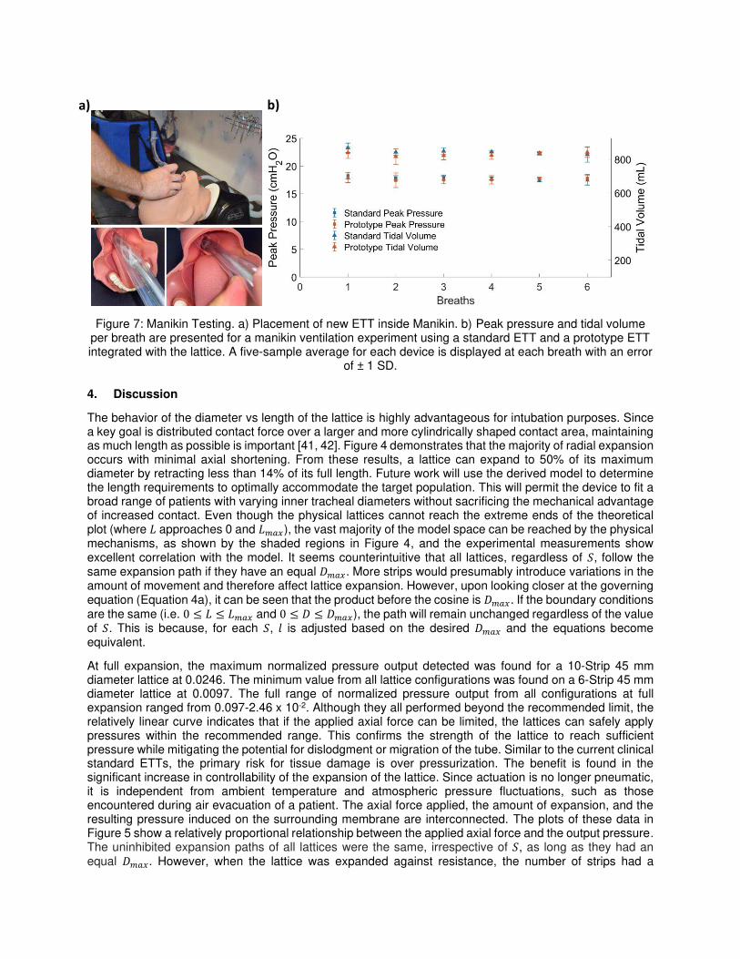
Figure 7: Manikin Testing. a) Placement of new ETT inside Manikin. b) Peak pressure and tidal volume per breath are presented for a manikin ventilation experiment using a standard ETT and a prototype ETT integrated with the lattice. A five-sample average for each device is displayed at each breath with an error
of ± 1 SD.
4. Discussion
The behavior of the diameter vs length of the lattice is highly advantageous for intubation purposes. Since a key goal is distributed contact force over a larger and more cylindrically shaped contact area, maintaining as much length as possible is important [41, 42]. Figure 4 demonstrates that the majority of radial expansion occurs with minimal axial shortening. From these results, a lattice can expand to 50% of its maximum diameter by retracting less than 14% of its full length. Future work will use the derived model to determine the length requirements to optimally accommodate the target population. This will permit the device to fit a broad range of patients with varying inner tracheal diameters without sacrificing the mechanical advantage of increased contact. Even though the physical lattices cannot reach the extreme ends of the theoretical plot (where 𝐿 approaches 0 and 𝐿𝑚𝑎𝑥), the vast majority of the model space can be reached by the physical mechanisms, as shown by the shaded regions in Figure 4, and the experimental measurements show excellent correlation with the model. It seems counterintuitive that all lattices, regardless of 𝑆, follow the same expansion path if they have an equal 𝐷𝑚𝑎𝑥. More strips would presumably introduce variations in the amount of movement and therefore affect lattice expansion. However, upon looking closer at the governing equation (Equation 4a), it can be seen that the product before the cosine is 𝐷𝑚𝑎𝑥. If the boundary conditions are the same (i.e. 0 ≤ 𝐿 ≤ 𝐿𝑚𝑎𝑥 and 0 ≤ 𝐷 ≤ 𝐷𝑚𝑎𝑥), the path will remain unchanged regardless of the value of 𝑆. This is because, for each 𝑆, 𝑙 is adjusted based on the desired 𝐷𝑚𝑎𝑥 and the equations become equivalent.
At full expansion, the maximum normalized pressure output detected was found for a 10-Strip 45 mm diameter lattice at 0.0246. The minimum value from all lattice configurations was found on a 6-Strip 45 mm diameter lattice at 0.0097. The full range of normalized pressure output from all configurations at full expansion ranged from 0.097-2.46 x 10⁻². Although they all performed beyond the recommended limit, the relatively linear curve indicates that if the applied axial force can be limited, the lattices can safely apply pressures within the recommended range. This confirms the strength of the lattice to reach sufficient pressure while mitigating the potential for dislodgment or migration of the tube. Similar to the current clinical standard ETTs, the primary risk for tissue damage is over pressurization. The benefit is found in the significant increase in controllability of the expansion of the lattice. Since actuation is no longer pneumatic, it is independent from ambient temperature and atmospheric pressure fluctuations, such as those encountered during air evacuation of a patient. The axial force applied, the amount of expansion, and the resulting pressure induced on the surrounding membrane are interconnected. The plots of these data in Figure 5 show a relatively proportional relationship between the applied axial force and the output pressure. The uninhibited expansion paths of all lattices were the same, irrespective of 𝑆, as long as they had an equal 𝐷𝑚𝑎𝑥. However, when the lattice was expanded against resistance, the number of strips had a
b) a)

significant impact on the mechanical response while 𝐷𝑚𝑎𝑥 did not. This finding, along with the demonstration that the number of strips impacts the nature of the strain and resulting pressure distribution, indicates that 𝑁 is a key variable for clinical deployment of the mechanism.
The results of the manikin experiments indicate the ability of the lattice integrated ETT to establish an equivalent seal with a standard ETT when it comes to resisting air leakage during manual ventilation. Peak pressure is the total airway pressure required to manually inflate a patient’s lungs when they are unable to breath on their own, thus making it an important aspect of assisted ventilation. The prototype also performed comparably to the current clinical standard for transporting air into the (manikin) patient’s lungs. Equivalent tidal volume per breath indicates the prototype’s ability to deliver a sufficient air supply to a patient requiring mechanical ventilation. No significant air volume was lost through leakage or flow resistance within the tube. These results, though only preliminary, provide motivation for more rigorous comparative analyses with standard tubes.
5. Conclusions
The expanding lattice cylinder has demonstrated the ability to produce radial pressures on a tracheal phantom tube within ranges clinically recommended for endotracheal intubation. The lattice accomplished this expansion by a purely mechanical actuation as opposed to the pneumatic inflation characteristic of current ETTs. The radial pressure is closely correlated to the axial force, suggesting improved control of the expansion and reduced risk of over pressurization. It was discovered that the responsiveness of the geometric expansion is independent from 𝑆. Conversely, the mechanical response of the tube (i.e. pressure) was found to be significantly affected by 𝑆. Greater values of 𝑆 were also found to improve the pressure distribution on the surrounding tube. This provides insight into the relationship between lattice configuration and tube performance, and by utilizing the derived models, can help to obtain an optimized design. It was also discovered that much of the expansion takes place with little reduction in the length of the lattice. This ensures the outer surface area remains cylindrically shaped and can have a favorable pressure distribution for nearly all adult patients. The results encourage the continuation of the development of a fully reengineered ETT. The novel lattice expansion mechanism addresses key deficiencies of the current clinical standard ETTs, and the data demonstrates that mitigation of these deficiencies and their related health complications is possible. The geometric behavior of the lattice makes it suitable for a one-size-fits-most application, simplifying the use of the tube and reducing the space required to have tubes on hand. This last point is particularly important for first responders and combat medics, who are required to carry all of their medical supplies in a pack. The smaller initial diameter eliminates the need for additional steps and equipment in the intubation procedure, such as bougie-assisted intubation. This can improve healthcare provider safety by streaming the intubation process and decreasing interaction with the patient. Integration of the lattice mechanism into an ETT prototype has been completed along with a preliminary comparative experiment in a manikin model. Future work will include additional testing against currently available ETTs in both in and ex vivo models. Our design serves as a platform for a safer, more effective alternative to standard ETTs. Successfully managing the applied pressure, achieving a one-size-fits-most model, and eliminating environmental effects, as well as being adaptable to further innovations such as robotic automation, are just a few aspects of this novel device that provide a high potential to significantly improve patient outcomes for both emergency and controlled ETIs.
Acknowledgements
This grant was funded in part by the San Antonio Medical Foundation. The authors would also like to extend thanks to Robert Brothers, Isaac Trevino, and Darnell Campbell for their support in the prototype development and background research of this work.
Competing interests: the authors have declared that no competing interest exists.
References
1. Cook, T.M., et al., Major complications of airway management in the UK: results of the Fourth National Audit Project of the Royal College of Anaesthetists and the Difficult Airway Society. Part

2: intensive care and emergency departments. British journal of anaesthesia, 2011. 106(5): p. 632-42.
2. Bucher, J.T., et al., Procedure rates performed by emergency medicine residents: a retrospective review. International journal of emergency medicine, 2018. 11(1): p. 7-7.
3. Pfuntner, A., L. Wier, and C. Stocks, Most frequent procedures performed in U.S. hospitals, 2011. 2014. p. 181-192.
4. Lapinsky, S.E., Endotracheal intubation in the ICU. Critical Care, 2015. 19(1): p. 258. 5. Pacheco-Lopez, P.C., et al., Complications of airway management. Respir Care, 2014. 59(6): p.
1006-19; discussion 1019-21. 6. Fan, C.M., et al., Tracheal rupture complicating emergent endotracheal intubation. Am J Emerg
Med, 2004. 22(4): p. 289-93. 7. Harris, R. and A. Joseph, Acute tracheal rupture related to endotracheal intubation: case report. J
Emerg Med, 2000. 18(1): p. 35-9. 8. Jahshan, F., et al., A novel rat model for assessment of laryngotracheal injury following transoral
intubation. International Journal of Pediatric Otorhinolaryngology, 2018. 113: p. 4-10. 9. Kastanos, N., et al., Laryngotracheal injury due to endotracheal intubation: incidence, evolution,
and predisposing factors. A prospective long-term study. Crit Care Med, 1983. 11(5): p. 362-7. 10. Kus, L.H., et al., Corrosion casting of the subglottis following endotracheal tube intubation injury: a
pilot study in Yorkshire piglets. J Otolaryngol Head Neck Surg, 2013. 42: p. 52. 11. Volpi, D., et al., Risk factors for intubation injury of the larynx. Ann Otol Rhinol Laryngol, 1987.
96(6): p. 684-6. 12. Wei, J.L. and J. Bond, Management and prevention of endotracheal intubation injury in neonates.
Curr Opin Otolaryngol Head Neck Surg, 2011. 19(6): p. 474-7. 13. Mota, L.A.A., G.B. de Cavalho, and V.A. Brito, Laryngeal complications by orotracheal intubation:
Literature review. International archives of otorhinolaryngology, 2012. 16(2): p. 236-245. 14. Martin, L.D., et al., 3,423 emergency tracheal intubations at a university hospital: airway outcomes
and complications. Anesthesiology, 2011. 114(1): p. 42-8. 15. Halhalli, H.C., et al., Benefits of using an endotracheal tube introducer as an adjunct to a Macintosh
laryngoscope for endotracheal intubation performed by inexperienced doctors during mechanical CPR: A randomized prospective crossover study. World journal of emergency medicine, 2019. 10(3): p. 182-186.
16. Messa, M.J., D.F. Kupas, and D.L. Dunham, Comparison of bougie-assisted intubation with traditional endotracheal intubation in a simulated difficult airway. Prehosp Emerg Care, 2011. 15(1): p. 30-3.
17. Sheu, Y.-J., et al., Comparison of the efficacy of a bougie and stylet in patients with endotracheal intubation: A meta-analysis of randomized controlled trials. Journal of Trauma and Acute Care Surgery, 2019. 86(5).
18. Bhatti, N.I., et al., Cost analysis of intubation-related tracheal injury using a national database. Otolaryngol Head Neck Surg, 2010. 143(1): p. 31-6.
19. Gaynor, E.B. and S.B. Greenberg, Untoward sequelae of prolonged intubation. Laryngoscope, 1985. 95(12): p. 1461-7.
20. Bangaari, A., B. Prabaharan, and T. Nair, Successful conservative management in post-intubation tracheal rupture. Indian journal of anaesthesia, 2012. 56(1): p. 85-87.
21. Stauffer, J.L., D.E. Olson, and T.L. Petty, Complications and consequences of endotracheal intubation and tracheotomy. A prospective study of 150 critically ill adult patients. Am J Med, 1981. 70(1): p. 65-76.
22. Chavez, S., et al., Coronavirus Disease (COVID-19): A primer for emergency physicians. The American Journal of Emergency Medicine.
23. Cooper, J.D., Tracheal Injuries Complicating Prolonged Intubation and Tracheostomy. Thorac Surg Clin, 2018. 28(2): p. 139-144.
24. Bulamba, F., et al., Achieving the Recommended Endotracheal Tube Cuff Pressure: A Randomized Control Study Comparing Loss of Resistance Syringe to Pilot Balloon Palpation. Anesthesiology Research and Practice, 2017.
25. Sinha, R., et al., Mucosal injury following short-term tracheal intubation: A novel animal model and composite tracheal injury score. Laryngoscope investigative otolaryngology, 2018. 3(4): p. 257-262.

26. Tennyson, J., et al., Endotracheal Tube Cuff Pressures in Patients Intubated Prior to Helicopter EMS Transport. Western Journal of Emergency Medicine, 2016. 17(6): p. 721-725.
27. Mariyaselvam, M.Z., et al., Endotracheal tubes and fluid aspiration: an in vitro evaluation of new cuff technologies. BMC Anesthesiology, 2017. 17(1): p. 36.
28. Young, P.J., et al., A low-volume, low-pressure tracheal tube cuff reduces pulmonary aspiration*. Critical Care Medicine, 2006. 34(3): p. 632-639.
29. Hagberg, C.A., et al., The incidence of gastroesophageal reflux and tracheal aspiration detected with pH electrodes is similar with the Laryngeal Mask Airway and Esophageal Tracheal Combitube--a pilot study. Can J Anaesth, 2004. 51(3): p. 243-9.
30. Black, L., M. Showe, and A. Steven, Molecular biology of bacteriophage T4. American Society for Microbiology, Wahington, DC, 1994.
31. Leiman, P.G., et al., Morphogenesis of the T4 tail and tail fibers. Virology Journal, 2010. 7(1): p. 355.
32. Miller, B.F. and C.B. Keane, Encyclopedia and dictionary of medicine, nursing, and allied health. 2d ed. 1978, Philadelphia: Saunders. xxiii, 1148 p.
33. Breatnach, E., G.C. Abbott, and R.G. Fraser, Dimensions of the normal human trachea. AJR Am J Roentgenol, 1984. 142(5): p. 903-6.
34. Garcia-Martin, R., et al., Combining digital image correlation and probabilistic approaches for the reliability analysis of composite pressure vessels. Archives of Civil and Mechanical Engineering, 2019. 19(1): p. 224-239.
35. Hild, F. and S. Roux, Digital Image Correlation: From Displacement Measurement to Identification of Elastic Properties - A Review. Strain, 2005. 42.
36. Revilock, D., J. Thesken, and T. Schmidt, Three-Dimensional Digital Image Correlation of a Composite Overwrapped Pressure Vessel During Hydrostatic Pressure Tests. 2007.
37. ASTM, Standard Test Method for Compressive Properties of Rigid Cellular Plastics. 2016, ASTM International: West Conshohocken, PA.
38. Roark, R.J. and W.C. Young, Formulas for stress and strain. 5th ed. 1975, New York: McGraw-Hill. xvi, 624 p.
39. Boonvisut, P., R. Jackson, and M.C. Cavuşoğlu, Estimation of Soft Tissue Mechanical Parameters from Robotic Manipulation Data. IEEE International Conference on Robotics and Automation : ICRA : [proceedings]. IEEE International Conference on Robotics and Automation, 2012. 2012: p. 4667-4674.
40. Trabelsi, O., et al., Experimental characterization and constitutive modeling of the mechanical behavior of the human trachea. Medical engineering & physics, 2010. 32(1): p. 76-82.
41. Bunegin, L., M.S. Albin, and R.B. Smith, Canine Tracheal Blood-Flow after Endotracheal-Tube Cuff Inflation during Normotension and Hypotension. Anesthesia and Analgesia, 1993. 76(5): p. 1083-1090.
42. Servin, S.O.N., et al., Atraumatic Endotracheal Tube for Mechanical Ventilation. Brazilian Journal of Anesthesiology, 2011. 61(3): p. 311-319.

Figures
Figure 1
Endotracheal Intubation. a) Schematic of Intubated Trachea. Image reproduced from [32]. b) Side-by-sidecomparison of novel ETT Prototype and Standard Size 8 ETT demonstrating a larger area of contactbased on expansion surface area. c) Demonstration of the novel device retracting to a diameter capableof insertion within a Size 8 ETT.

Figure 2
Assembled Lattice. a) Flattened S=6 lattice showing strip position and naming convention, positive strips(blue) and negative strips (orange), and primary/secondary strip length variables labeled. b) Top and sideview of snap-�tting joint �xtures (top) and actuation motion (bottom). c) Side view of constructed latticeillustrating oscillating unit lattices (blue and orange) and ending segments of A-A’ strips (purple). d) Frontview of constructed lattice showing various geometric variables and what they represent in the physicalmodel. e) Expanded lattice viewed from above with joint positions (orange) and circumferential stripsection (blue) highlighted.

Figure 3
Experimental Setup: a) DIC camera array with sample loaded in tensile tester. b) Lattice and elastictrachea phantom mounted in tensile tester with load cell.

Figure 4
Experimental data superimposed on top of theoretical plot of diameter vs length expansion path. Theshaded area represents the achievable expansion range for a 39 mm lattice (a) and 45 mm lattice (b).

Figure 5
a) Plots of axial force vs axial displacement. b) Pressure (normalized by 0.029 MPa and 3.33 MPa elasticmodulus for silicone and tracheal tissue, respectively) vs axial displacement with shaded band for thenormalized recommended pressure range for 6-, 8-, and 10-strip lattices with 45 mm maximum diameter,various data points have been displayed.

Figure 6
a) Axial Strain Gradient (eyy) of Lattices at 5 mm axial displacement, from left to right: 6-Strip, 8-Strip,and 10-Strip Lattices, all with maximum diameter of 39 mm. The line used to evaluate the strain can beseen with white points at either end. b) Frequency distribution of strain values across the strain gradient�elds
Figure 7

Manikin Testing. a) Placement of new ETT inside Manikin. b) Peak pressure and tidal volume per breathare presented for a manikin ventilation experiment using a standard ETT and a prototype ETT integratedwith the lattice. A �ve-sample average for each device is displayed at each breath with an error of ± 1 SD.