novel 3d force sensor using ultra-thin silicon strain...
TRANSCRIPT
NOVEL 3D FORCE SENSOR USING ULTRA-THIN SILICON STRAIN GAUGE BONDED ON METAL MEMBRANE
Y. D. Kim1 , Y. D. Kim2, C. S. Lee2, and S. J. Kwon1
1 KAIST, Daejeon, Republic of Korea
2Tyco Electronics, Gyeongsan, Republic of Korea ABSTRACT
In the present paper, we propose a novel 3D force sensor design using a silicon strain gauge bonded on a metal diaphragm. The fabrication process and glass frit bonding process of the ultra-thin silicon strain gauges having a thickness of 50 μm were established; afterward, performance of the silicon strain gauge bonded on the stainless steel cantilever beam was evaluated at the various conditions. In results, resistance linearly increased with deformation by tensile stress, and gauge factor representing the sensitivity of the strain gauge was 33.77. Nonlinearity and hysteresis were respectively 0.21%FS and 0.17%FS.
KEYWORDS
3D force sensor, MEMS strain gauge, Poly-Si strain gauge, ultra-thin strain gauge, glass frit bonding INTRODUCTION
A sensor is a device that measures a physical, chemical and biological quantity, and converts it into an electric signal which can be read by an observer or by an instrument. Force sensors, pressure sensors and accelerometer sensors using strain gauges are representative physical sensors [1]. Recently, advances in micromachining technology permit the design and fabrication of MEMS force sensors which have larger sensitivity and several orders of magnitude smaller size than conventional ones. Metal foil strain gauges are used in a typical force sensor design. Comparing with silicon strain gauges, metal foil strain gauges have about 10~20 times lower sensitivity. Silicon strain gauges are formed on the diaphragm in a typical force sensor design. The conventional diaphragm material of the silicon force sensor is also silicon which is fabricated by a silicon wet etching process [2-6]. However, it is difficult to make the silicon diaphragms having various size and structures due to the limitation of the MEMS fabrication process. In contrast, the metal diaphragms having various size and structures are easily and inexpensively realized since the processing of a metal is simple and well-known. Moreover, metal membrane has isotropic elastic constants, while the silicon membrane has anisotropic elastic constants.
Thus, we designed the 3D force sensor using the ultra-thin silicon strain gauges bonded on metal diaphragms. To realize this concept, we established the fabrication process of the silicon strain gauge and the bonding process between the metal diaphragm and the silicon strain gauge. Afterward, Performance of the silicon strain gauge bonded
(a)
(b)
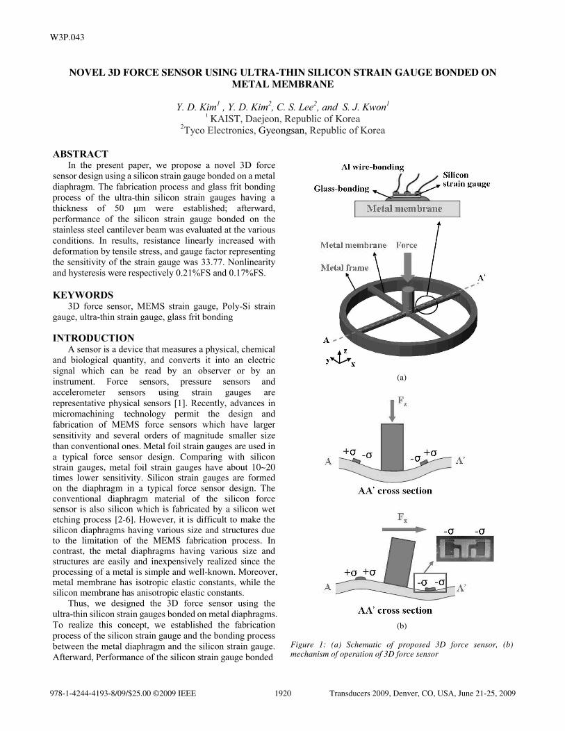
Figure 1: (a) Schematic of proposed 3D force sensor, (b) mechanism of operation of 3D force sensor
978-1-4244-4193-8/09/$25.00 ©2009 IEEE Transducers 2009, Denver, CO, USA, June 21-25, 20091920
W3P.043
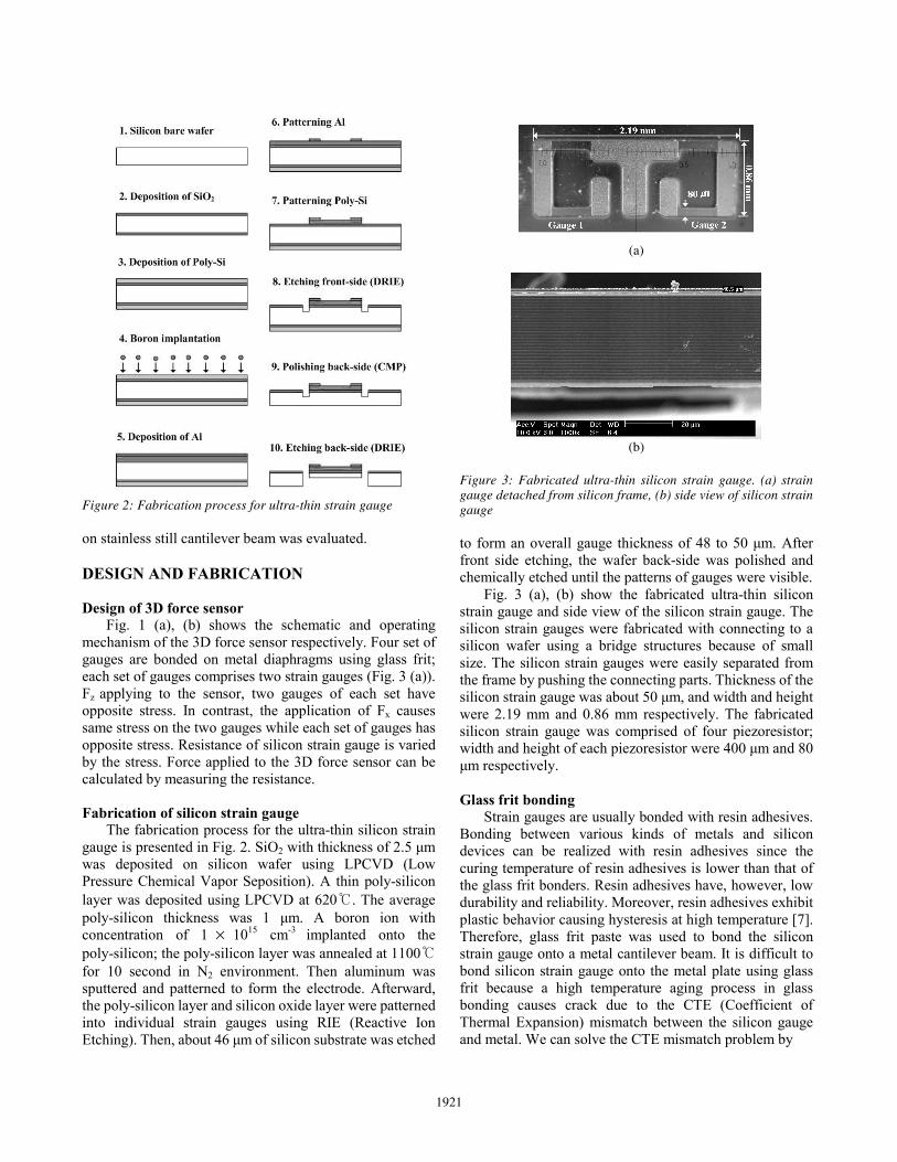
Figure 2: Fabrication process for ultra-thin strain gauge on stainless still cantilever beam was evaluated. DESIGN AND FABRICATION
Design of 3D force sensor
Fig. 1 (a), (b) shows the schematic and operating mechanism of the 3D force sensor respectively. Four set of gauges are bonded on metal diaphragms using glass frit; each set of gauges comprises two strain gauges (Fig. 3 (a)). Fz applying to the sensor, two gauges of each set have opposite stress. In contrast, the application of Fx causes same stress on the two gauges while each set of gauges has opposite stress. Resistance of silicon strain gauge is varied by the stress. Force applied to the 3D force sensor can be calculated by measuring the resistance.
Fabrication of silicon strain gauge
The fabrication process for the ultra-thin silicon strain gauge is presented in Fig. 2. SiO2 with thickness of 2.5 μm was deposited on silicon wafer using LPCVD (Low Pressure Chemical Vapor Seposition). A thin poly-silicon layer was deposited using LPCVD at 620℃. The average poly-silicon thickness was 1 μm. A boron ion with concentration of 1 × 1015 cm-3 implanted onto the poly-silicon; the poly-silicon layer was annealed at 1100℃ for 10 second in N2 environment. Then aluminum was sputtered and patterned to form the electrode. Afterward, the poly-silicon layer and silicon oxide layer were patterned into individual strain gauges using RIE (Reactive Ion Etching). Then, about 46 μm of silicon substrate was etched
(a)
(b)
Figure 3: Fabricated ultra-thin silicon strain gauge. (a) strain gauge detached from silicon frame, (b) side view of silicon strain gauge
to form an overall gauge thickness of 48 to 50 μm. After front side etching, the wafer back-side was polished and chemically etched until the patterns of gauges were visible.
Fig. 3 (a), (b) show the fabricated ultra-thin silicon strain gauge and side view of the silicon strain gauge. The silicon strain gauges were fabricated with connecting to a silicon wafer using a bridge structures because of small size. The silicon strain gauges were easily separated from the frame by pushing the connecting parts. Thickness of the silicon strain gauge was about 50 μm, and width and height were 2.19 mm and 0.86 mm respectively. The fabricated silicon strain gauge was comprised of four piezoresistor; width and height of each piezoresistor were 400 μm and 80 μm respectively.
Glass frit bonding
Strain gauges are usually bonded with resin adhesives. Bonding between various kinds of metals and silicon devices can be realized with resin adhesives since the curing temperature of resin adhesives is lower than that of the glass frit bonders. Resin adhesives have, however, low durability and reliability. Moreover, resin adhesives exhibit plastic behavior causing hysteresis at high temperature [7]. Therefore, glass frit paste was used to bond the silicon strain gauge onto a metal cantilever beam. It is difficult to bond silicon strain gauge onto the metal plate using glass frit because a high temperature aging process in glass bonding causes crack due to the CTE (Coefficient of Thermal Expansion) mismatch between the silicon gauge and metal. We can solve the CTE mismatch problem by
1921

(a)
(b)
Figure 4: (a) Metal mask for screen printing of glass frit past, (b) silicon gauge bonded on stainless still cantilever beam using glass frit
Figure 5: Experimental setup to evaluate performance of silicon gauge
using the ultra-thin silicon strain gauge which is more expandable than the thick silicon strain gauge. The final thickness of the silicon strain gauge was about 50 μm.
The cantilever beam was made of SUS630 stainless steel having high yield point and small CTE. Yield point and CTE of SUS630 stainless steel are 1000 MPa and 11.6 μm/m/℃ respectively. Glass frit bonding is carried out in four main steps: the pre-treatment of the surface of the cantilever beam, the deposition of the glass frit paste using print screen method, elimination of a solvent and an organic binder material, bonding between the silicon strain gauge and the metal cantilever beam. Organic materials on the metal cantilever beam were eliminated in a solution of 5% hydrochloric acid for 10 minutes; cantilever beam was cleaned with DI water. Then the glass frit paste was screen-printed with a metal mask (Fig. 4 (a)). The height of
Figure 6: Normalized resistance as a function of strain
Figure 7: Nonlinearity as a function of strain
Figure 8: Hysteresis as a function of strain
the printed glass frit paste was about 150 μm. The glass frit paste is comprised of solvent, organic binders and glass frit. The solvent and organic binders should be eliminated before bonding step. The solvent can be eliminated at 100 ℃, and the organic binders can be burned out at 350 ℃. Afterward, the silicon strain gauge was placed; bonding step was carried out at 505 ℃. Final thickness of glass frit layer was about 100 μm since the solvent and organic
1922
binders were eliminated. Fig. 4 (b) shows the glass-bonded gauge on metal cantilever beam. RESULT AND DISCUSSION
Performance of the silicon strain gauge was evaluated at the various conditions. Fig. 5 shows the experimental setup. The endpoint deflection of the cantilever beam was measured by the IR displacement sensor (Z4M-W40, OMRON). Then the strain of the silicon strain gauge, xε , can be calculated with equation (1):
33( )
2xL x h
Lε δ−= × (1)
where L , h and δ represent the length, thickness and endpoint deflection of the cantilever beam respectively. The length and the thickness of the cantilever beam were 200 mm and 3 mm.
Fig. 6 shows normalized resistance changes as a function of strain. Resistance linearly increased when the gauge was deformed by tensile stress. Gauge factor which represent the sensitivity of the sensor can be calculated with equation (2):
0 0( ( ) ) /R R RGF εε
−= (2)
where ( )R ε and 0R express resistance of the silicon strain gauge at strain ε and zero strain respectively. Gauge factor of the silicon strain gauge was 33.77 which was about 10~20 times larger than gauge factor of the metal foil strain gauge. Comparing with previous study, gauge factor is higher [5]. Fig. 7 shows nonlinearity as a function of strain at room temperature. Nonlinearity means the maximum deviation of the actual value from a straight line positioned to coincide with the actual upper and lower range values. Maximum value of nonlinearity was 0.21%FS. Fig. 8 shows hysteresis as a function of strain at room temperature. Hysteresis is a measure of the repeatability of resistance of the strain gauge over the operating force range after one or more cycles. Maximum value of hysteresis was 0.17%FS. Nonlinearity and hysteresis were lower than those of Cu-Ni alloy strain gauge [8]. CONCLUSION
In the present paper, the novel 3D force sensor design using the ultra-thin silicon strain gauge bonded on a metal diaphragm is proposed. To realize this concept, the fabrication process and glass frit bonding process of the ultra-thin silicon strain gauges having a thickness of 50 μm were established. Performance of the silicon strain gauge bonded on the stainless steel cantilever beam was evaluated. In results, resistance linearly increased with tensile stress while decreased with compressible stress. Gauge factor representing the sensitivity of the strain gauge was about 33.77 that was much larger than that of conventional metal foil strain gauges. Nonlinearity and
hysteresis were respectively 0.21%FS and 0.17%FS which were lower than those of the Cu-Ni metal alloy strain gauges. ACKNOWLEDGEMENT
This work was supported by the Korea Science and Engineering Foundation(KOSEF) grant funded by the Korea government(MEST) (No. R0A_2007_000_20065_0) REFERENCES: [1] G. T. Kovacs, MICROMACHINED TRANSDUCERS
SOURCEBOOK, McGraw-Hill, New York, USA, 1998.
[2] P. Ruther, J. Bartholomeyczik, S. Trautmann, M. Wandt, O. Paul, W.R. Dominicus, W. Strauss, “Novel 3D piezoresistive silicon force sensor for dimensional metrology of micro components,” IEEE Sensors 2005. pp. 1006-1009, 2005.
[3] A. Tibrewala, A. Phataralaoha, S. Buttgenbach, “Simulation, fabrication and characterization of a 3D piezoresistive force sensor,” Sensors and Actuators A, vol. 147, pp. 430–435, 2008.
[4] Daniel Lopez, Ricardo S. Decca, Ephraim Fischbach, Dennis E. Krause, “MEMS-Based Force Sensor: Design and Applications,” Bell Labs Technical Journal, vol. 10, no. 3, pp. 61–80, 2005.
[5] M Gel and I Shimoyama, “Force sensing submicrometer thick cantilevers with ultra-thin piezoresistors by rapid thermal diffusion,” J. Micromech. Microeng. vol. 14, pp. 423–428, 2004.
[6] H. Schӓ fer, "Temperature-indipendent Pressure Sensors Using Polycrystalline Silicon Strain Gauges," Sensor and Actuators, Vol. 17, pp. 521-527, 1989.
[7] W. A. Leasure, N. Woodruff, and C. Gravel, "Glass-bonding Techniques for Semiconductor Strain Gauge," SESA Spring Meeting, pp. 235-240, 1970.
[8] Birkelund, K., Gravesen, P. and Shiryaev, S., “High-pressure silicon sensor with low-cost packaging,” Sensors and Actuators A, Vol. 92, pp. 16-22, 2001.
CONTACT * S. J. Kwon, tel: +82-42-350-3721; [email protected]
1923