notice simplifiéebreve descrizione - festo.com file1. benutzerhinweise. die ’hochstromausgänge 2...
TRANSCRIPT

0
1
2
3
HC-OUTPUT
9709 NH
Kurzbeschreibung
Hochstromausgängefür
VentilinselTyp 03/05VIEA-..-
Brief Description
High current outputsfor valveterminals
types 03/05VIEA-..-
Notice simplifiée
Sorties de puissancepour terminaux de
distributeurs type 03
à 05 VIEA-..-
Breve descrizione
Uscite ad altoassorbimento elettrico
per unità di valvoletipo 03/05VIEA-..-
Beskrivning
Högeffektsutgångarför
ventilterminaltyp 03/05VIEA-..-
Breve descripción
Salidas de alta corientepara terminales de
válvulastipos 03/05
VIEA-..-
379
251

Deutsch . . . . . . . . . . . . . . . . . . . . . . . . . . . . . . . . . . . . . . 3
English . . . . . . . . . . . . . . . . . . . . . . . . . . . . . . . . . . . . . . . 9
Español . . . . . . . . . . . . . . . . . . . . . . . . . . . . . . . . . . . . . 15
Français . . . . . . . . . . . . . . . . . . . . . . . . . . . . . . . . . . . . . 21
Italiano . . . . . . . . . . . . . . . . . . . . . . . . . . . . . . . . . . . . . . 27
Svenska . . . . . . . . . . . . . . . . . . . . . . . . . . . . . . . . . . . . . 33
(Festo AG & Co., D-73726 Esslingen, 1997)
VIEA - 03/05
9709 NH 2
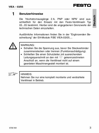
1 Benutzerhinweise
Die ’Hochstromausgänge 2 A, PNP oder NPN’ sind aus-schließlich für den Einsatz mit den Festo-Ventilinseln Typ03...05 bestimmt. Hierbei sind die angegebenen Grenzwerte dertechnischen Daten einzuhalten.
Ausführliche Informationen finden Sie in der "Ergänzenden Be-schreibung" der EA-Module P.BE VIEA-03/05....
WARNUNG:• Schalten Sie die Spannung aus, bevor Sie Steckverbinder
zusammenstecken oder trennen (Funktionsschädigung).• Schließen Sie einen Schutzleiter mit ausreichendem
Leitungsquerschnitt an den mit gekennzeichneten Anschluß an, wenn die Ventilinsel nicht auf einem geerdeten Maschinengestell montiert ist.
HINWEIS:Nehmen Sie nur eine komplett montierte und verdrahteteVentilinsel in Betrieb.
Deu
tsch
VIEA - 03/05
9709 NH 3

2 Montage
HINWEIS:• Achten Sie bei den Hochstromkontakten besonders auf:
– Exaktes Ansetzen der Buchsen.– Zusammengesteckte Module sofort verschrauben.– Verschraubung ohne Verzug und mechanische
Spannung.• Grundsätzlich gilt:
maximal 12 elektrische Module pro Insel (incl. Zusatzeinspeisung).
Normale HC-Module HC-Module "Normale EA-Module" und Zusatz- und Zusatz- EA-Module"
einspeisung einspeisung
1
2
2*
EA-Modul 4-/8 Eingänge (PNP/NPN) oder 4 Ausgänge (nur PNP 0,5 A) oder Multi-EA-Modul 12E/8AHC-Output (PNP/NPN)Hochstrom-Versorgung (graue Verbindung)endet nach dem letzten HC-Output-Modul
3
4
5
Zusatzeinspeisung24 V/25 AKnotenVentile
222*1 2*13 2 3 1 1 4 5
Deu
tsch
VIEA - 03/05
4 9709 NH

3 Anschlußbelegung
3.1 Hochstromausgänge PNP
Buchse Bedeutung
0 1 2 3
1 1 – – Output Ox+1
2 PE
3 0 V
4 – – – Output Ox
– 5 – 5 n.c. (not connected)
– – 6 – Output Ox+2
– – 7 7 Output Ox+3
8 interne Verbindung im Modul
2
1
3
4
2
5
3
1
8
0
1
2
7
3
6
2
5
3
7
8
2
3
Deu
tsch
VIEA - 03/05
9709 NH 5

3.2 Hochstromausgänge NPN
Buchse Bedeutung
0 1 2 3
1 1 1 1 PE
2 DC 24 V Verbraucher/Last mußüber diesen 24 V-Anschlußversorgt werden
3 3 – – Output Ox+1
4 – – – Output Ox
– 5 – 5 n.c. (not connected)
– – 6 6 Output Ox+3
– – 7 – Output Ox+2
8 interne Verbindung im Modul
2
1
3
4
2
1
5
3
8
0
1
2
1
6
7
2
1
5
6
8
2
3
Deu
tsch
VIEA - 03/05
6 9709 NH
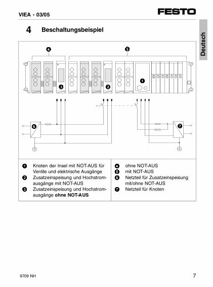
4 Beschaltungsbeispiel
1
2
3
Knoten der Insel mit NOT-AUS fürVentile und elektrische AusgängeZusatzeinspeisung und Hochstrom-ausgänge mit NOT-AUSZusatzeinspeisung und Hochstrom-ausgänge ohne NOT-AUS
4
5
6
7
ohne NOT-AUSmit NOT-AUSNetzteil für Zusatzeinspeisungmit/ohne NOT-AUSNetzteil für Knoten
6 7
23
1
54
Deu
tsch
VIEA - 03/05
9709 NH 7

5 Technische Daten
Elektrische Hochstromausgänge (PNP oder NPN)
Ausführung• HC-OUTPUT
(Typenschild: VIGA-03-FB-4-PH)• HC-OUTPUT-N
(Typenschild: VIGA-03-FB-4-NH)
PNP-Halbleiterschalter (positive Logik), nach IEC 1131-2NPN-Halbleiterschalter (negative Logik), nach IEC 1131-2
Betriebsspannung (verpolungssicher)
Spannungsabfall über geschaltetem Ausgang
24 V ± 25 %
0,7 V
Belastbarkeit• pro digitalem Ausgang
(Lampenlast oder induktive Last)• Parallelschaltung zulässig (max. vier
Hochstromausgänge eines Moduls)
max. 2,0 A
auf gleichmäßige Belastung achten
Eigenstromaufnahme pro Modul max. 100 mA
Elektronische Sicherung (Kurzschluß/Überlast)• Auslösestrom• Ansprechzeit (Kurzschluß)• Kurzschlußerholzeit
min. 2,5 As. Tabelle Kapitel 2.3min. 1 s
Galvanische Trennung ja
Intregrierte Schutzbeschaltung zumSchalten induktiver Lasten• PNP, Begrenzung auf• NPN, Begrenzung auf
ja
ca. - 6 V bezogen auf 0 Vca. + 12 V bezogen auf 24 V
Elektromagnetische Verträglichkeit (EMV) Grenzwertklasse: siehe "Beschreibung Elektronik" Ihrer Insel
Deu
tsch
VIEA - 03/05
8 9709 NH

1 User instructions
The 2 A, PNP or NPN high current outputs are intended exclu-sively for use with Festo valve terminals types 03...05. The spe-cified limits in the technical data must be observed.
Detailed information can be found in the supplementary descrip-tion of the I/O modules P.BE VIEA-03/05....
WARNING• Switch off the power supply before you connect or
disconnect plugs (danger of functional damage).• Connect a protective earth conductor with sufficient cross
section to the connection marked with , if thevalve terminal is not fitted on an earthed machine stand.
PLEASE NOTEOnly operate a valve terminal which is completely fitted andelectrically wired.
En
glis
h
VIEA - 03/05
9709 NH 9

2 Fitting
PLEASE NOTE• Observe especially the following with regard to the
high current contacts:– the sockets must be correctly aligned– the combined modules must be screwed
together immediately– the screw connectors must not be distorted or subjected
to mechanical stress.• The following always applies:
maximum 12 electrical modules per terminal(incl. additional supply).
Normal HC modules HC modules NormalI/O modules and additional and additional I/O modules
supply supply
1
2
2*
I/O module 4/8 inputs (PNP/NPN) or 4 outputs (only PNP 0.5 A) or multi-I/O module 12I/8OHC output (PNP/NPN)High current supply (grey connection) endsafter last HC output module
3
4
5
Additional supply24 V/25 ANodeValves
222*1 2*13 2 3 1 1 4 5
En
glis
hVIEA - 03/05
10 9709 NH
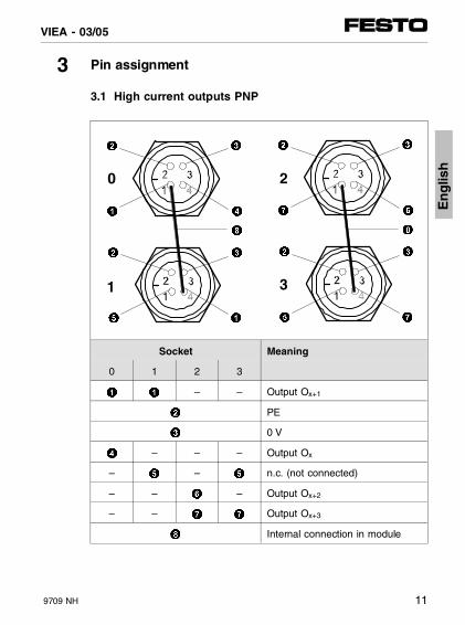
3 Pin assignment
3.1 High current outputs PNP
Socket Meaning
0 1 2 3
1 1 – – Output Ox+1
2 PE
3 0 V
4 – – – Output Ox
– 5 – 5 n.c. (not connected)
– – 6 – Output Ox+2
– – 7 7 Output Ox+3
8 Internal connection in module
2
1
3
4
2
5
3
1
8
0
1
2
7
3
6
2
5
3
7
8
2
3
En
glis
h
VIEA - 03/05
9709 NH 11

3.2 High current outputs NPN
Socket Meaning
0 1 2 3
1 1 1 1 PE
2 24 V DC Consumer/load mustbe supplied via this 24 Vconnection
3 3 – – Output Ox+1
4 – – – Output Ox
– 5 – 5 n.c. (not connected)
– – 6 6 Output Ox+3
– – 7 – Output Ox+2
8 Internal connection in module
2
1
3
4
2
1
5
3
8
0
1
2
1
6
7
2
1
5
6
8
2
3
En
glis
hVIEA - 03/05
12 9709 NH

4 Circuitry example
1
2
3
Node of terminal withEMERGENCY STOP for valvesand electrical outputsAdditional supply and high currentoutputs with EMERGENCY STOPAdditional supply and high currentoutputs without EMERGENCYSTOP
4
5
6
7
Without EMERGENCY STOPWith EMERGENCY STOPPower unit for additionalsupply with/withoutEMERGENCY STOPPower unit for node
6 7
23
1
54
En
glis
h
VIEA - 03/05
9709 NH 13

5 Technical specifications
Electrical high current outputs (PNP or NPN),
Design • HC OUTPUT
(type plate: VIGA-03-FB-4-PH) • HC OUTPUT N
(type plate: VIGA-03-FB-4-NH)
PNP semi conductor switch (positive logic) as per IEC 1131-2NPN semi conductor switch(negative logic) as per IEC 1131-2
Operating voltage (protected against incor-rect polarity)Voltage drop at switched output
24 V ( 25%)
0.7 V
Loading capacity • per digital output
(bulb load or inductive load) • parallel circuit permitted (max. four
high current outputs of a module)
max. 2.0 A
Check for even loading
Internal current consumption per module max. 100 mA
Electronic fuse (short circuit/overload) • trigger current • response time (short circuit) • short circuit recovery time
min. 2.5 ASee table chapter 2.3 min.min. 1 s
Electrical isolation Yes
Integrated protective circuit for switching in-ductive loads• PNP limited to • NPN limited to
approx. - 6 V related to 0 V approx. + 12 V related to 24 V
Electromagnetic compatibility (EMC) Limit class: see the "Electronics Manual" foryour terminal
En
glis
hVIEA - 03/05
14 9709 NH

1 Instrucciones para el usuario
Las salidas de alta corriente de 2 A, PNP o NPN están diseña-das exclusivamente para ser utilizadas con los terminales deválvulas Festo, tipos 03...05. Deben observarse los valores lími-te de las especificaciones técnicas.
Puede hallarse información detallada en la descripción suple-mentaria de los módulos de I/O P.BE VIEA-03/05...
ATENCION:• Desconectar la alimentación antes de conectar o
desconectar clavijas (riesgo de daños funcionales).• Utilizar un conductor de tierra de protección con sección
suficiente en la conexión marcada con si el terminal de válvulas no está montado en un bastidor puesto a tierra.
POR FAVOR, OBSERVAR:Poner en marcha el terminal de válvulas solamente cuandoesté completamente montado y cableado.
Esp
año
l
VIEA - 03/05
9709 NH 15

2 Montaje
POR FAVOR, OBSERVAR:• En relación con los contactos de alta corriente, observar
especialmente lo siguiente:– los zócalos deben estar correctamente alineados– los módulos combinados deben atronillarse juntos
inmediatamente– los conectores roscados no deben quedar forzados ni
sujetos a esfuerzos mecánicos.• Se aplica siempre lo siguiente:
máximo 12 módulos eléctricos por terminal(incl. la alimentación adicional).
Módulos Módulos HC Módulos HC MódulosI/O normales y alimentación y alimentación I/O normales
adicional adicional
1
2
2*
Módulo I/O 4/8 inputs (PNP/NPN) o 4 outputs (sólo PNP 0,5 A) o módulo multi-I/O 12I/8OOutput HC (PNP/NPN)La alimentación de alta corriente (conexióngris) termina después del último módulo deOutputs HC
3
4
5
Alimentaciónadicional 24 V/25 ANodoVálvulas
222*1 2*13 2 3 1 1 4 5Esp
año
lVIEA - 03/05
16 9709 NH

3 Asignación de pines
3.1 Salidas PNP de alta corriente
Zócalo Significado
0 1 2 3
1 1 – – Output Ox+1
2 PE
3 0 V
4 – – – Output Ox
– 5 – 5 n.c. (no conectado)
– – 6 – Output Ox+2
– – 7 7 Output Ox+3
8 Conexión interna en el módulo
2
1
3
4
2
5
3
1
8
0
1
2
7
3
6
2
5
3
7
8
2
3
Esp
año
l
VIEA - 03/05
9709 NH 17

3.2 Salidas NPN de alta coriente
Zócalo Significado
0 1 2 3
1 1 1 1 PE
2 El consumidor/carga de 24 V DCdebe alimentarse a través deesta conexión de 24 V
3 3 – – Output Ox+1
4 – – – Output Ox
– 5 – 5 n.c. (no conectada)
– – 6 6 Output Ox+3
– – 7 – Output Ox+2
8 Conexión interna en el módulo
2
1
3
4
2
1
5
3
8
0
1
2
1
6
7
2
1
5
6
8
2
3
Esp
año
lVIEA - 03/05
18 9709 NH

4 Circuito de ejemplo
1
2
3
Nodo de terminal con PARO DEEMERGENCIA para válvulas ysalidas eléctricasAlimentación adicional y salidas dealta corriente con PARO DEEMERGENCIAAlimentación adicional y salidas dealta corriente sin PARO DE EMERGENCIA
4
5
6
7
Sin PARO DE EMERGENCIACon PARO DE EMERGENCIAUnidad de potencia paraalimentación adicional con/sinPARO DE EMERGENCIAUnidad de potencia para elnodo
6 7
23
1
54
Esp
año
l
VIEA - 03/05
9709 NH 19
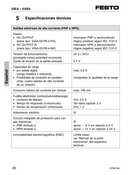
5 Especificaciones técnicas
Salidas eléctricas de alta corriente (PNP o NPN),
Diseño • HC OUTPUT
(placa tipo: VIGA-03-FB-4-PH) • HC OUTPUT N
(placa tipo: VIGA-03-FB-4-NH)
interruptor PNP a semiconductor(lógica positiva) según IEC 1131-2interruptor NPN a semiconductor(lógica negativa) según IEC 1131-2
Tensión de funcionamiento (protegida contra polaridad incorrecta)Caída de tensión en la salida activada
24 V ( 25%)
0,7 V
Capacidad de carga• por salida digital
(carga resistiva o inductiva) • Posibilidad de conexión en paralelo
(máx. cuatro salidas de alta corriente de un módulo)
máx. 0,2 A
Comprobar la igualdad de la carga
Consumo interno de corriente por módulo máx. 100 mA
Fusible electrónico (cortocircuito/sobrecarga)• corriente de disparo• tiempo de respuesta (cortocircuito) • tiempo de recuperación cortocircuito
mín. 2,5 AVer tabla capítulo 2.3mín. 1 s
Aislamiento eléctrico Si
Circuito integrado de protección para car-gas inductivas• PNP limitado a• NPN limitado a
Siaprox. - 6 V en relación a 0 V aprox. + 12 V en relación a 24 V
Compatibilidad electromagnética (EMC) Límite clase: ver "Manual de la parteelectrónica" del respectivoterminal
Esp
año
lVIEA - 03/05
20 9709 NH

1 Instructions d’utilisation
Les sorties de puissance 2 A, PNP ou NPN sont exclusivementdestinées aux terminaux de distributeurs Festo type 03 à 05.Les valeurs limites indiquées dans les caractéristiques techni-ques doivent être respectées.
Le " Complément " au manuel d’utilisation des modules d’E/SP.BE VIEA-03/05.... fournit de plus amples informations.
ATTENTION :• Mettre hors tension avant de raccorder ou de débrancher
des connecteurs (risques de dégradations).• Raccorder un conducteur de protection de section
suffisante sur la borne repérée par le symbole , dansle cas où le terminal de distributeurs n’est pas installé surun bâti de machine lui-même relié à la terre.
REMARQUE :Ne mettre le terminal de distributeurs en service que lorsquele montage et le raccordement sont totalement terminés. F
ran
çais
VIEA - 03/05
9709 NH 21

2 Montage
REMARQUE :• Pour les contacts de puissance, veiller particulièrement :
– à mettre les connecteurs en place correctement – à fixer immédiatement les modules combinés ensemble – à ne pas créer de déformation ou de contrainte lors de
la fixation• Respecter la règle suivante :
installer au maximum 12 modules électriques par terminal (y compris l’alimentation auxiliaire)
Module d’E/S Module HC Module HC Module d’E/S courant avec alim. avec alim. courant
auxiliaire auxiliaire
1
2
2*
Module d’E/S à 4 ou 8 entrées (PNP/NPN) ou 4 sorties (PNP 0,5 A seulement) ou module à E/S multiples 12E/8AHC-Output (PNP/NPN)Alimentation de puissance (liaison en grisé)se terminant derrière le dernier module HC-Output
3
4
5
Alimentationauxiliaire 24 V/25 ANoeudDistributeurs
222*1 2*13 2 3 1 1 4 5
Fra
nça
isVIEA - 03/05
22 9709 NH

3 Affectation des broches
3.1 Sorties de puissance PNP
Broche Signification
0 1 2 3
1 1 – – Output Ox+1
2 PE
3 0 V
4 – – – Output Ox
– 5 – 5 n.c. (not connected)
– – 6 – Output Ox+2
– – 7 7 Output Ox+3
8 liaison interne au module
2
1
3
4
2
5
3
1
8
0
1
2
7
3
6
2
5
3
7
8
2
3
Fra
nça
is
VIEA - 03/05
9709 NH 23

3.2 Sorties de puissance NPN
Broche Signification
0 1 2 3
1 1 1 1 PE
2 24 V DC Alimenter lesconsommateurs ou les chargesà travers ce contact 24 V
3 3 – – Output Ox+1
4 – – – Output Ox
– 5 – 5 n.c. (not connected)
– – 6 6 Output Ox+3
– – 7 – Output Ox+2
8 liaison interne au module
2
1
3
4
2
1
5
3
8
0
1
2
1
6
7
2
1
5
6
8
2
3
Fra
nça
isVIEA - 03/05
24 9709 NH

4 Exemple de connexion
1
2
3
Noeud du terminal avec ARRETD’URGENCE pour les distributeurset les sorties électriques Alimentation auxiliaire et sorties depuissance avec ARRET D’URGENCEAlimentation auxiliaire et sorties depuissance sans ARRET D’URGENCE
4
5
6
7
sans ARRET D’URGENCE avec ARRET D’URGENCE Bloc d’alimentation auxiliaireavec/sans ARRET D’URGENCEBloc d’alimentation du noeud
6 7
23
1
54
Fra
nça
is
VIEA - 03/05
9709 NH 25

5 Caractéristiques techniques
Sorties de puissance électriques (PNP ou NPN)
Modèle• HC-OUTPUT
(plaque signalétique : VIGA-03-FB-4-PH)• HC-OUTPUT-N
(plaque signalétique : VIGA-03-FB-4-NH)
Contact PNP à semi-conducteurs (logique positive), selon IEC 1131-2Contact NPN à semi-conducteurs (logique négative), selon IEC 1131-2
Tension d’alimentation (protégé contre l’inversion de polarité)Chute de tension sur la sortie commutée
24 V ± 25 %
0,7 V
Charge admissible• par sortie TOR
(charge résistive ou inductive)• mise en parallèle admise (au max.les
quatre sorties de puissance d’un module)
2,0 A
Veiller à répartir la charge
Consommation propre par module 100 mA max.
Fusible électronique (court-circuit/surcharge)• courant de déclenchement• temps de réponse (court-circuit)• temps de suppression du court-circuit
2,5 A min.voir tableau chapitre 2.31 s min.
Isolation galvanique oui
Contact de protection intégré pour lacommutation de charges inductives• PNP, limitation à• NPN, limitation à
oui
env. - 6 V par rapport au 0 Venv. + 12 V par rapport au 24 V
Compatibilité électromagnétique (CEM) Classe : voir le manuel "Electronique" du terminal
Fra
nça
isVIEA - 03/05
26 9709 NH

1 Indicazioni per l’utilizzatore
Le ’uscite ad alto assorbimento elettrico a 2 A, con logica PNPo NPN’ sono destinate esclusivamente all’impiego all’internodelle unità di valvole FESTO tipo 03...05 nel rispetto dei limitiprevisti per i parametri tecnici.
Informazioni dettagliate sono reperibili nella descrizione integra-tiva dei moduli I/O P.BE VIEA-03/05....
AVVERTENZA:• Disinserire la tensione prima di collegare
o scollegare i connettori (danni funzionali).• Se il telaio su cui è installata l’unità di valvole non
è collegato a massa, connettere un conduttore di protezione di sezione adeguata all’attacco contrassegnato dal simbolo .
NOTA:Utilizzare solamente unità di valvole completamente assem-blate e cablate.
Italia
no
VIEA - 03/05
9709 NH 27
2 Montaggio
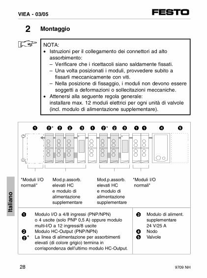
NOTA:• Istruzioni per il collegamento dei connettori ad alto
assorbimento:– Verificare che i ricettacoli siano saldamente fissati.– Una volta posizionati i moduli, provvedere subito a
fissarli meccanicamente con viti.– Nella posizione di fissaggio, i moduli non devono essere
soggetti a deformazioni o sollecitazioni meccaniche.• Attenersi alla seguente regola generale:
installare max. 12 moduli elettrici per ogni unità di valvole (incl. modulo di alimentazione supplementare).
"Moduli I/O Mod.p.assorb. Mod.p.assorb. "Moduli I/O normali" elevati HC elevati HC normali"
e modulo di e modulo di alimentazione alimentazione supplementare supplementare
1
2
2*
Modulo I/O a 4/8 ingressi (PNP/NPN) o 4 uscite (solo PNP 0,5 A) oppure modulomulti-I/O a 12 ingressi/8 usciteModulo HC-Output (PNP/NPN)La linea di alimentazione per assorbimentielevati (di colore grigio) termina incorrispondenza dell’ultimo modulo HC-Output.
3
4
5
Modulo di aliment.supplementare 24 V/25 ANodoValvole
222*1 2*13 2 3 1 1 4 5
Italia
no
VIEA - 03/05
28 9709 NH

3 Occupazione dei pin
3.1 Uscite ad alto assorbimento elettrico PNP
Connettore Significato
0 1 2 3
1 1 – – Output Ox+1
2 PE
3 0 V
4 – – – Output Ox
– 5 – 5 n.c. (not connected)
– – 6 – Output Ox+2
– – 7 7 Output Ox+3
8 Collegamento interno al modulo
2
1
3
4
2
5
3
1
8
0
1
2
7
3
6
2
5
3
7
8
2
3
Italia
no
VIEA - 03/05
9709 NH 29

3.2 Uscite ad alto assorbimento elettrico NPN
Connettore Significato
0 1 2 3
1 1 1 1 PE
2 Il cavo di alimentazione delleutenze/carichi a 24 VCC deveessere condotto attraversoquesto collegamento a 24 V.
3 3 – – Output Ox+1
4 – – – Output Ox
– 5 – 5 n.c. (not connected)
– – 6 6 Output Ox+3
– – 7 – Output Ox+2
8 Collegamento interno al modulo
2
1
3
4
2
1
5
3
8
0
1
2
1
6
7
2
1
5
6
8
2
3
Italia
no
VIEA - 03/05
30 9709 NH

4 Esempio di collegamento
1
2
3
Nodo dell’unità di valvole concircuito di emergenza per levalvole e le uscite elettricheModulo di alimentazionesupplementare e uscitead alto assorbimento elettrico conEMERGENZAModulo di alimentazionesupplementare e uscitead alto assorbimento elettricosenza EMERGENZA
4
5
6
7
Senza EMERGENZACon EMERGENZA Alimentatore supplementarecon/senza EMERGENZA Alimentatore nodo
6 7
23
1
54
Italia
no
VIEA - 03/05
9709 NH 31

5 Dati tecnici
Uscite ad alto assorbimento elettrico (PNP / NPN)
Esecuzione• HC-OUTPUT
(targhetta di identificazione: VIGA-03-FB-4-PH)• HC-OUTPUT-N
(targhetta di identificazione: VIGA-03-FB-4-NH)
interruttore a semiconduttore PNP (logica positiva), a norme IEC 1131-2interruttore a semiconduttore NPN(logica negativa), a norme IEC 1131-2
Tensione di esercizio (a prova di inversione di polarità)Caduta di tensione ad uscita commutata
24 V ± 25 %
0,7 V
Carico ammissibile• per ogni uscita digitale
(carico delle lampade o induttivo)• collegamento in parallelo consentito
(max. quattro uscite ad alto assorbimentoelettrico di un modulo)
max.2,0 A
verificare che il carico sia uniforme
Assorbimento elettrico interno di ogni modulo max. 100 mA
Fusibile per l’elettronica (cortocircuito/sovraccarico)• corrente di azionamento• tempo di intervento (cortocircuito)• tempo di recupero
min. 2,5 Avedi tabella Cap. 2.3min. 1 s
Isolamento galvanico presente
Circuito di protezione incorporato per ilcollegamento di carichi induttivi• PNP, limitazione • NPN, limitazione
presente
ca. - 6 V rif. a 0 Vca. + 12 V rif. a 24 V
Compatibilità elettromagnetica (EMC) Classe valore limite: vedere la descrizionedell’elettronica dell’unità di valvole in uso
Italia
no
VIEA - 03/05
32 9709 NH

1 Användaranvisningar
Modulerna med högeffektsutgångarna 2 A, PNP eller NPN äruteslutande avsedda för användning med Festos ventiltermina-ler 03 och 05. Därvid ska de angivna gränsvärdena för tekniskadata hållas.
Utförlig information finns i Kompletteringsmanualen för I/O-mo-dulerna P.BE VIEA-03/05....
VARNING:• Koppla från spänningen, innan kontakten
sätts in eller dras ur (risk för funktionsskada).• Anslut en skyddsledare med tillräckligt ledningstvärsnitt
till den anslutning som är märkt med , om inte ventil-terminalen är monterad på ett jordat maskinstativ.
OBSERVERA:Ta endast en komplett monterad och kopplad ventilterminal i drift.
Sve
nska
VIEA - 03/05
9709 NH 33
2 Montering
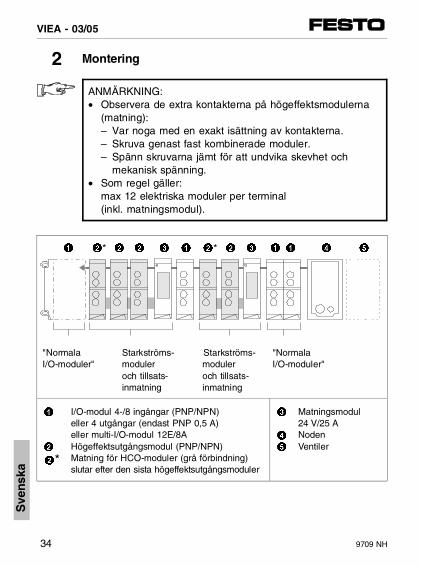
ANMÄRKNING:• Observera de extra kontakterna på högeffektsmodulerna
(matning):– Var noga med en exakt isättning av kontakterna.– Skruva genast fast kombinerade moduler.– Spänn skruvarna jämt för att undvika skevhet och
mekanisk spänning.• Som regel gäller:
max 12 elektriska moduler per terminal (inkl. matningsmodul).
"Normala Starkströms- Starkströms- "Normala I/O-moduler" moduler moduler I/O-moduler"
och tillsats- och tillsats-inmatning inmatning
1
2
2*
I/O-modul 4-/8 ingångar (PNP/NPN) eller 4 utgångar (endast PNP 0,5 A) eller multi-I/O-modul 12E/8AHögeffektsutgångsmodul (PNP/NPN)Matning för HCO-moduler (grå förbindning)slutar efter den sista högeffektsutgångsmoduler
3
4
5
Matningsmodul24 V/25 ANodenVentiler
222*1 2*13 2 3 1 1 4 5
Sve
nska
VIEA - 03/05
34 9709 NH

3 Stiftbeläggning
3.1 Högeffektsutgångar PNP
Kontakt Betydelse
0 1 2 3
1 1 – – Utgång Ox+1
2 Jord (PE)
3 0 V
4 – – – Utgång Ox
– 5 – 5 Ej ansluten
– – 6 – Utgång Ox+2
– – 7 7 Utgång Ox+3
8 Intern anslutning i modulen
2
1
3
4
2
5
3
1
8
0
1
2
7
3
6
2
5
3
7
8
2
3
Sve
nska
VIEA - 03/05
9709 NH 35

3.2 Högeffektsutgångar NPN
Kontakt Betydelse
0 1 2 3
1 1 1 1 Jord (PE)
2 DC 24 V förbrukare/belastningmåste försörjas via denna 24 V-anslutning
3 3 – – Utgång Ox+1
4 – – – Utgång Ox
– 5 – 5 Ej ansluten
– – 6 6 Utgång Ox+3
– – 7 – Utgång Ox+2
8 Intern anslutning i modulen
2
1
3
4
2
1
5
3
8
0
1
2
1
6
7
2
1
5
6
8
2
3
Sve
nska
VIEA - 03/05
36 9709 NH

4 Kopplingsexempel
1
2
3
Terminalens nod med NÖDSTOPPför ventiler och elektriska utgångarMatningsmodul och högeffekts-utgångar utan NÖDSTOPPMatningsmodul och högeffekts-utgångar utan NÖDSTOPP
4
5
6
7
Utan NÖDSTOPPMed NÖDSTOPPNätdel för matningsmodulernamed/utan NÖDSTOPPNätdel för noden
6 7
23
1
54
Sve
nska
VIEA - 03/05
9709 NH 37

5 Tekniska data
Högefeffektsutgångar (PNP eller NPN)
Utförande• HÖGEFFEKTSUTGÅNGAR
(Typskylt: VIGA-03-FB-4-PH)• HÖGEFFEKTSUTGÅNG-N
(Typskylt: VIGA-03-FB-4-NH)
PNP-halvledarbrytare (positiv logik), enligt IEC 1131-2NPN-halvledarbrytare (negativ logik), enligt IEC 1131-2
Driftspänning (polomkastningssäker)
Spänningsfall via kopplad utgång
24 V ± 25 %
0,7 V
Belastningsbarhet• per digital utgång
(resestiv eller induktiv last)• Parallelkoppling tillåten (max. fyra
utgångar från en modul)
max. 2,0 A
beakta jämn belastning
Egen strömförbrukning per modul max. 100 mA
Elektronisk säkring (kortslutning/överbelastning)• Utlösningsström• Tillslagstid (kortslutning)• Återhämtningstid vid kortslutning
min. 2,5 Ase tabell kapitel 2.3min. 1 s
Elektrisk isolering ja
Skyddskretsar är integrerade för omkoppling av induktiva belastningar• PNP, begränsad till• NPN, begränsad till
ja
ca. - 6 V i relation till 0 Vca. + 12 V i relation till 24 V
Elektromagnetisk kompatibilitet (EMC) Gränsvärdesklass: se "Manual för elektronik" för din terminal
Sve
nska
VIEA - 03/05
38 9709 NH