notes (slides with comment/pdf) - maxon motor ag
TRANSCRIPT

maxon EC motor An introduction to brushless DC motors
Page 1 © 2012, maxon motor ag, www.maxonmotor.com/academy
This presentation introduces the design and operation principle of the brushless
maxon EC motors. EC motors are also called brushless DC (BLDC) motors.
• In a first part we show the basic designs of brushless maxon motors
• The second part treats some common features: the operating principle which
is based on the interaction between the magnetic fields of permanent magnet
and winding. Additionally we give information about the winding connection of
three phase motors and iron losses.
• In the third part we have a closer look at the different electronic commutation
systems, i.e. how the electronics switches the current on the three phases.
• At the end we compare these brushless motor designs to maxon DC motors
with mechanical commutation.

maxon EC motor An introduction to brushless DC motors
Page 2 © 2012, maxon motor ag, www.maxonmotor.com/academy
Let's first look at an EC drive system in general.
The three phases of the EC motor cannot be connected directly to a DC power supply. The
voltage needs to be switched in a sequence. This is done by the electronic commutation. For
the correct switching the electronics needs rotor position information from the motor. This
information is usually provided by the Hall sensors.
An EC motor cannot operate on its own: It's always the combination of motor and electronics
commutation that makes the full drive.
For more sophisticated commutation and precise motor control, e.g. at very low speeds, the use of
an encoder feedback might be necessary. Often the electronics not only performs the
commutation but at the same time can be used to control speed or position.

maxon EC motor An introduction to brushless DC motors
Page 3 © 2012, maxon motor ag, www.maxonmotor.com/academy
maxon EC motors are brushless DC motors. The EC stands for electronic commutation to
distinguish these motors from DC motors with mechanical commutation by a brush system.
The arrangement of rotor and stator in brushless DC motors reminds strongly of synchronous or
stepper motors. However, there is a big difference to these motor types: It's the powering of
the 3 phases which is done according to the internal rotor position and not imposed from
outside.
The windings of an EC motor are powered similarly as in a brushed DC motor – the electronic
commutation mimicking the brush system. Therefore, there is the same speed-torque
behavior as with any DC motor. In particular the high starting torque and the resulting high
dynamics are obtained as well.
The main advantage of a brushless design is the longer motor life and the higher motor speed.
They are not limited by the mechanical commutation system.
maxon EC motors come in slotted and slotless design. Slotless winding design with the traditional
maxon winding system have similar advantages as the coreless maxon DC motors: There is
no magnetic detent and, therefore, less vibration and noise.
Brushless motors have become more and more attractive over the last 2 decades. Mainly
because the electronics necessary for operation became less expensive and smaller in size.
Furthermore the development of high power Neodymium magnets allowed the rotor mass inertia
to be reduced and, hence, the dynamics to be increased.

maxon EC motor An introduction to brushless DC motors
Page 4 © 2012, maxon motor ag, www.maxonmotor.com/academy
maxon EC motors come in different designs.
First, there are the slotless design variants based on the rhombic maxon winding.
Then there are designs where the winding is wound on a slotted iron core.
However there are some common features of all these EC motors.
• The winding has 3 phases. The winding must be on the stator, because there is no brush
system that could transmit the current on a rotating winding. (And the motor connections
should not be wound up at 10'000rpm!)
• Consequently, it's the permanent magnet that rotates. Usually the magnetic material is
NdFeB to get a high power density.
• maxon brushless motors are equipped with preloaded ball bearings. In the absence of
brushes it's the bearing system that limits motor life. Preloaded ball bearing are one of the
most promising system to achieve a high service life.
• And of course all EC motors need commutation electronics to operate.

maxon EC motor An introduction to brushless DC motors
Page 5 © 2012, maxon motor ag, www.maxonmotor.com/academy
The first design variant that we want to look at is the classical maxon EC motor design based on
the coreless maxon winding.
Three motor families in the maxon catalog comply with this design.
• maxon EC motor: These motors have a permanent magnet with 1 pole pair. Their speed is
quite high (up to 100'000 rpm). maxon EC motors come in many different types: The diameter
ranges from 6 to 60 mm. Often there are a short and a long version per diameter. Some
motors are sterilisable, some have the electronics integrated.
• maxon EC-max: The "max" refers to maximum performance to price ratio. This motor is not
optimized for high power – be it high speed or high torque - but for reasonable low cost. For
many applications that don't need very high speeds or torque (e.g. in combination with
gearheads) this reliable motor is just perfect. The diameters range from 16 to 40 mm.
• maxon EC-4pole: The philosophy of these motors with 2 magnetic pole pairs is to provide the
highest power. Besides the 4-pole design this is achieved by a special winding arrangement
and highest quality magnetic materials.
In the following let's look at some details.

maxon EC motor An introduction to brushless DC motors
Page 6 © 2012, maxon motor ag, www.maxonmotor.com/academy
On the maxon EC motor we can distinguish the following main subassemblies:
• The rotor with the permanent magnet mounted on the shaft at the center. Dynamic balancing
is achieved by removing material from the two balancing rings made of brass. Balancing is
important for reducing vibration and noise and for increasing bearing life, particularly at the
high speeds obtainable with brushless motors.
• The stator contains the housing with the magnetic return. The magnetic return is made of an
laminated iron stack in order to reduce the iron losses due to the rotating permanent magnet.
Inside the iron stack we have the maxon winding, the three phases are contacted via the
printed circuit board (PCB) to the electrical winding connections.
• Rotor position feedback is often achieved by a system of three Hall sensor mounted on the
PCB. The Hall sensors detect the magnetic field of a control magnet which is attached to the
shaft. In some cases the magnetic field of the main permanent magnet is monitored directly.
The Hall sensors have 5 additional electrical connections: 2 for the supply voltage and 3 for the
Hall sensor signals.
• The ball bearings are often preloaded with a spring.

maxon EC motor An introduction to brushless DC motors
Page 7 © 2012, maxon motor ag, www.maxonmotor.com/academy
What are the main differences between a cost optimized EC-max and a power optimized EC-4pole motor? We make this comparison on motors with 30 mm diameter.
Enhancing the power density on the EC-4pole is achieved by
• 4 permanent magnetic poles instead of 2, i.e. 2 pole pairs instead of 1. This results in a higher total magnetic flux in the air gap. The assembly of the rotor, however, is more complicated; there are 4 magnetized segments that need to be mounted on the shaft.
• a high grade iron-nickel magnetic return. The magnetization frequency in the magnetic return is twice as high as on a motor with 1 pole pair. In order to keep the eddy current losses small this high performance material is used. The maximum magnetic flux density, however, is smaller allowing a thinner magnetic return. This gives more space for the winding and the rotor diameter can be made slightly larger. Both factors have a positive effect on the produced torque.
• a hexagonally shaped knitted maxon winding. The hexagonal winding can result in a higher motor torque. A further torque increase is achieved by a sophisticated connection of the winding segments.
The higher power of this motor needs a stronger shaft and larger bearings.
Reducing the cost on the EC-max 30 is achieved by
• a simpler rotor, with no balancing. However, this requires low tolerances and a precise mounting of the magnets. There is some unbalance left; thus, the motors should not be used at very high speeds.
• a standard maxon winding instead of a knitted winding. This reduces performance.
• Hall sensors monitoring directly the power magnet, i.e. without extra control magnet.
Interestingly, the lack of balancing rings and control magnet allow a longer magnetic system. Even if this motor is not optimized with respect to power there is quite a lot of torque generated.

maxon EC motor An introduction to brushless DC motors
Page 8 © 2012, maxon motor ag, www.maxonmotor.com/academy
Here again the most important design characteristics of the EC-max product range.

maxon EC motor An introduction to brushless DC motors
Page 9 © 2012, maxon motor ag, www.maxonmotor.com/academy
And here we have the characteristics of the EC-4pole product range.

maxon EC motor An introduction to brushless DC motors
Page 10 © 2012, maxon motor ag, www.maxonmotor.com/academy
Let's now turn to the slotted maxon EC motors.
These motors have some common features which makes them commercially attractive.
• The slotted windings can be produced at lower cost than the coreless maxon winding.
• The multi-pole magnet are made from isotropic Neodymium magnets instead of the anisotropic
ones in the slotless designs.
There are some other technical features which are similar on both designs.
• The high number of magnetic poles results in quite a high produced torque, though it limits
the maximum speed due to the higher magnetization frequencies.
• The slotted design results in a slight cogging torque.
The behavior however is quite different, because of the different arrangement of winding and
rotor.
• The EC-i with the external winding and the magnet close to the center exhibits a high torque
per mass inertia of the rotor. This results in a very dynamic motor with fast acceleration.
• The external rotor of the EC-flat produces the force far from the rotating axis. This gives a very
high torque. But the large rotor diameter causes the rotor mass inertia to be high as well.
Therefore, the dynamics is limited. The flat design can be an advantage in certain applications
with limited space available.

maxon EC motor An introduction to brushless DC motors
Page 11 © 2012, maxon motor ag, www.maxonmotor.com/academy
This slide shows a cross section of an EC 32 flat motor.
• We can see the external rotor magnet ring with 8 magnetic poles (4 pole pairs in green and
red).
• Each winding phase is made of two stator teeth lying opposite.
• The Hall sensors (dark and bright blue) are located between the stator teeth and monitor
directly the poles of the magnetic ring.

maxon EC motor An introduction to brushless DC motors
Page 12 © 2012, maxon motor ag, www.maxonmotor.com/academy
In this second part we would like to have a closer look at three features.
The first feature is the interaction between the magnetic fields of rotor and stator, i.e. the
principle of how a permanent uniform torque is generated. We do this in a simplified way on
the maxon EC motor with one pole pair. We will later see what changes occur if the number of
pole pair is enhanced.
First we observe that the three phases allow 6 different ways of how current can flow through the
motor. (Here we make the assumption that the supply voltage is applied to two of the winding
connections at a time.)
For one current distribution the winding produces a magnetic field which points diagonally across
the motor. According to the 6 current possibilities there are 6 magnetic field directions
separated by 60°.
Comments on the animation:
The permanent magnet of the rotor tries to align with this field produced by the winding. However,
we do not allow this. The torque has a maximum at the perpendicular orientation of the two
fields. Thus, we switch the current 30° before and after the perpendicular positions. In this way
the generated torque is always close to the maximum.
The angle between two consecutive switching (or commutation) is 60°.
The big question that arises is: How do we know when to commutate?
We need to know the angular rotor position. A traditional way is to use the Hall sensor signals.
This will be explained later in the part 3 of this presentation.

maxon EC motor An introduction to brushless DC motors
Page 13 © 2012, maxon motor ag, www.maxonmotor.com/academy
A second feature we would like to discuss shortly is the internal winding connection.
Basically, a three phase winding can be considered as made up of three equal parts represented
here as resistances R. There are two ways of arranging these resistances in a symmetric
manner: The well known Star (or Wye) and Delta connections.
What is the difference of the two arrangements?
- Although the star circuit has a higher terminal resistance (by a factor of three) the power
losses are the same for the same operating point (torque, speed).
- The star circuit has the higher torque constant. This means that with the same amount of
current more torque is generated than in a delta configuration.
- The delta circuit has the higher speed constant. Hence less voltage is needed to reach the
same speed, or with a given voltage a higher speed can be reached.
These findings could be summarized as: Two motors with the same winding once in star once in
delta configuration behave like two motors with windings made of different wire diameter. One
needs a higher current but a lower voltage than the other to reach the same torque and speed.
For maxon motors the arrangement star or delta is fixed. For motor operation and commutation
this information is not needed. The only practical consequence of a delta circuit could be that in
unfavorable conditions circular winding currents might be induced.

maxon EC motor An introduction to brushless DC motors
Page 14 © 2012, maxon motor ag, www.maxonmotor.com/academy
Iron losses occur in most motor types. These are power losses in the iron parts that guide the
magnetic flux, namely the magnetic return path and the iron core of slotted windings. Iron
losses provide an additional heating of the motor.
Iron losses are caused by two mechanisms, both relying on the fact that the flux in the iron
changes its direction or intensity.
• Hysteresis losses describe the fact that changing the magnetization of the iron consumes
energy. It's similar to running through the magnetization loop (hysteresis) of the material.
Hysteresis losses can be minimized by selecting appropriate materials that can easily be
magnetized (with a narrow hysteresis) and by lowering the flux density (i.e. selecting a large
diameter of the material).
• The changing magnetic flux induces voltages in the material. These voltages produce eddy
currents in the iron which will be heated. Eddy currents can be minimized by selecting a
laminated iron return made of thin iron foil which are electrically isolated. One can show that
the more confined the eddy currents are the lower the losses.
Iron losses and speed
• Hysteresis losses increase proportional to motor speed. Each hysteresis cycle adds a certain
amount of energy loss: The higher the speed, the higher the number of magnetization cycles
per time, the higher the power losses. Therefore, hysteresis losses can be treated like an
additional constant friction torque.
• Eddy current losses increase with the square of the speed. This can be understood from a
simple argument: The faster the speed the higher the induced voltage and the higher the eddy
current. Power losses go with the square of the current, hence, with the square of the speed. In
short, eddy current losses can be treated like a speed dependent additional friction torque.
• If the speed is sufficiently high it's the eddy current losses that dominate. This additional
heating can be seen in the operating range diagram. At high speeds the limit of the continuous
operating range moves towards lower torques. The additional heating by the eddy current
allows less current in the winding and, hence less torque.

maxon EC motor An introduction to brushless DC motors
Page 15 © 2012, maxon motor ag, www.maxonmotor.com/academy
In this third part of the presentation we would like to understand the electronic commutation.
There are different systems. maxon uses the following three:
• Block commutation with or without Hall sensors
• Sinusoidal commutation.
As you can see the different maxon controller families perform different commutation types.
Common to all these systems is that they should apply the current in a way, that the generated
torque is as high as possible. As we have learned this is achieved by a perpendicular
orientation of the magnetic fields of permanent magnet and winding. We have seen as well
that we need to know the orientation of the permanent magnet to achieve this.
We start with block commutation with Hall sensor position feedback. That's the standard
commutation type. Once we have understood this the two other commutation schemes are
easily derived from it.

maxon EC motor An introduction to brushless DC motors
Page 16 © 2012, maxon motor ag, www.maxonmotor.com/academy
First we have to look at the Hall sensor feedback signals. Again we do this based on the
simplest design, the slotless maxon EC motor with 1 pole pair.
In the back of the motor there are three Hall sensor mounted on the PCB at an angle of 120°. The
Hall sensor detect the magnetic poles of the control magnet which is mounted on the shaft.
The control magnet exhibits the same two magnetic poles in the same orientation as the power
magnet. (Basically the Hall sensors could monitor the power magnet directly but the control
magnet offers two advantages: The magnetic transitions between north and south pole are
more precisely defined. And an angular misalignment and tolerances between the relative
position of winding and Hall sensors can be adjusted.)
The digital Hall sensors used probe the direction of the magnetic field. They generates a high
output signal (5V) if the north pole of the control magnet is close to them. A south pole
produces a low level (Gnd).
The actual position of the control magnet in the diagram generates the following signals:
• The blue Hall sensor sees the north pole. Thus the signal output level is high and will remain
high for the next 120°.
• The green Hall sensor is close to the south pole. The output level is low for the next 60°. Then
the north pole approaches and the output signal will switch to a high state.
• The red Hall sensor has just switched from high to low where the signal level will stay for the
next half a turn.
The combination of the three Hall sensor signals is unique for each 60° of rotation. Looking at
these signals allows to know the rotor position within 60°. That exactly what we need for
commutation. Remember there were 6 different ways of current flow through the motor at a
commutation angle of 60°.
The next slide shows how the complete block commutation system works.

maxon EC motor An introduction to brushless DC motors
Page 17 © 2012, maxon motor ag, www.maxonmotor.com/academy
On the right we have a schematic cross section of a maxon EC motor with 2 pole permanent
magnet in the center, the three phase winding and the three Hall sensors placed at 120°. For
simplicity we assume the Hall sensors to probe the power magnet directly.
On the left we have the commutation electronics which is fed with a DC supply voltage. There
is a power bridge made of 6 MOSFETs. Three of them are needed to contact the motor phases
to the positive supply voltage. The lower three MOSFETs make the contact to the supply
ground. The power bridge is controlled by a commutation logic that evaluates the Hall sensor
signals and, accordingly, switches the power on the three motor phases.
Comments on the animation:
• In this starting position the Hall sensors give the following signal: HS1 has just switched to a
high state, HS2 is low and HS3 is high.
• The commutation logic knows that for this signal combination and clockwise motor rotation the
current must flow from phase 1 to 2 and powers the respective two MOSFETs.
• The winding produces a magnetic field and the magnetic rotor tries to align.
• After 60° the HS3 starts seeing the south pole. Its output switches to low and the commutation
logic switches the current from phase 1 to 3. The field of the winding advances by 60° and the
rotor continues to rotate.
• Again after 60° the Hall sensor pattern changes, HS2 switches to a high output level.
Accordingly the electronics commutates the current to flow from phase 2 to 3. Again the field of
the winding advances by another 60° and the rotor continues.
• And so on … . After 6 commutation intervals we are back at the initial configuration and the
rotor has accomplished one turn.

maxon EC motor An introduction to brushless DC motors
Page 18 © 2012, maxon motor ag, www.maxonmotor.com/academy
Let's now look at the same block commutation sequence of a multi-pole motor.
The magnetic interaction is shown in a simplified picture that considers just the attraction of opposite and repulsion of similar magnetic poles.
Again we take the example of EC 32 flat. We remember that this motor has 4 magnetic pole pairs in the rotor. The winding has 3 phases, each with 2 stator teeth lying opposite. The Hall sensors are located between the stator teeth. (A high output level is indicated by a bright blue color.)
On the left is the block commutation diagram that can be found in the maxon catalog. The rotor position scale is adapted to the actual example of the EC 32 rotor.
Comments on the animation:
• In this starting position the Hall sensors give the following signal: HS1 has just switched to a high state, HS2 is low and HS3 is high.
• The commutation logic knows that for this signal combination and clockwise motor rotation the current must flow from phase 1 to 2 and powers the corresponding two MOSFETs.
• The stator teeth become north poles at phase 1 and south poles at phase 2. These poles attract the opposite poles of the permanent magnetic rotor (and repel the poles with the same polarity). The rotor starts to turn.
• After 15° the HS3 starts seeing the south pole. Its output switches to low and the commutation logic applies the current between phases 1 and 3. Accordingly the south poles of the winding appear on phase 3.
• Remark: In order to achieve a high torque it is necessary that the opposite poles of rotor and stator do not approach each other too much. Because this produces forces that point towards the rotating axis and not in a tangential direction and the generated torque will be smaller.
• The rotor continues to rotate. Again after 15° the Hall sensor pattern changes, HS2 switches to a high output level. Accordingly the electronics commutates the current to flow from phase 2 to phase 3. Phase 1 is switched off and the north poles can now be found on the teeth of phase 2.
• The rotor continues, and so on … . After 6 commutation intervals we are back at the initial configuration, but this time the rotor has only travelled 6*15° = 90°. This is the major difference for a multi-pole motor: The commutation angle equals 60° divided by the number of pole pairs (P) on the rotor. Or, for the same speed the commutation frequency must be P times higher.

maxon EC motor An introduction to brushless DC motors
Page 19 © 2012, maxon motor ag, www.maxonmotor.com/academy
Up to this point we have considered "Block commutation with Hall sensors".
But if you look in the maxon catalog you find sensorless motors with just the three winding connections and no Hall sensors at all. How can these motors be operated when there is no position information from the Hall sensors?
There is another way of getting the necessary position information from the motor. Let's consider a motor with one pole pair with a winding in star configuration.
There is always one phase of the winding which is not powered. But this phase will see the rotating permanent magnet which induces a sinusoidal voltage in this phase – the back EMF. One can show that exactly in the middle of the 60° of block commutation (when the phase is not powered) the induced voltage crosses zero. This voltage crossing can be detected if the star point of the winding is accessible as well.
Then one has to wait until 30° of rotation have passed and do the next switching of block commutation. (The tricky thing is to have speed information as well in order to know when the 30° have passed. But this can be done more or less precisely, e.g. from the time distance of the previous zero-crossings).
During the next commutation interval one looks at the next phase that is not powered and so on.
There is one problem. When speed is low the amplitude of the EMF becomes smaller and smaller. The slope of the EMF voltage becomes flatter and flatter and it is difficult to determine exactly the zero crossing. Even worse, at zero speed (e.g. during start-up) there is no back EMF at all!
This means that sensorless commutation does not work well at low speeds (typically below approx. 1000 rpm for motors with 1 pole pair) and it needs a special starting procedure which is done similar to a stepper motor. I.e. the windings are powered according to the block commutation sequence without taking note of the EMF. The commutation frequency is enhanced and if anything goes well the rotor will speed up. Once a certain minimum speed is reached the back EMF is taken into consideration and the real sensorless block commutation is established.
In order to get a reliable starting up the parameters of the start-up procedure must be selected carefully depending on motor characteristics and load (friction, mass inertia, …).

maxon EC motor An introduction to brushless DC motors
Page 20 © 2012, maxon motor ag, www.maxonmotor.com/academy
We have seen that sensorless block commutation needs the star point of the winding. But on
many sensorless motors this point is not accessible; there are just the connections to the three
phases.
However there is a way of getting the potential of the star point without physical access to it. In the
electronics three resistances are set up in star configuration in parallel to the motor winding.
The resistances in the electronics are much higher in order to have the current still flowing
through the motor. But the voltage levels are the same. And now it is easy to measure the back
EMF on each phase individually with the help of the virtual star point in the electronics.
The nice thing is: It even works for motors in delta configuration where there is no star point at all.
(Again this shows that it is not necessary to know whether a winding is in star or delta
configuration.)

maxon EC motor An introduction to brushless DC motors
Page 21 © 2012, maxon motor ag, www.maxonmotor.com/academy
Block commutation with or without Hall sensors is characterized by the abrupt switching of the
current every 60°, or every 60° divided by the number of pole pairs, respectively. The term
"block commutation" is derived from these block shaped phase currents.
The torque within one commutation interval is not uniform, it will vary a little. This can cause
excitations that can be seen as vibration or audible noise. Very low speeds might not be
uniform.
The motor data in the maxon catalog are given for block commutation with Hall sensors.
maxon EC motor An introduction to brushless DC motors
Page 22 © 2012, maxon motor ag, www.maxonmotor.com/academy
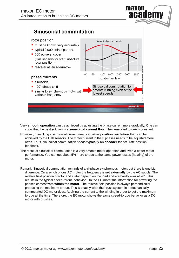
Very smooth operation can be achieved by adjusting the phase current more gradually. One can
show that the best solution is a sinusoidal current flow. The generated torque is constant.
However, mimicking a sinusoidal current needs a better position resolution than can be
achieved by the Hall sensors. The motor current in the 3 phases needs to be adjusted more
often. Thus, sinusoidal commutation needs typically an encoder for accurate position
feedback.
The result of sinusoidal commutation is a very smooth motor operation and even a better motor
performance. You can get about 5% more torque at the same power losses (heating) of the
motor.
Remark: Sinusoidal commutation reminds of a tri-phase synchronous motor, but there is one big
difference. On a synchronous AC motor the frequency is set externally by the AC supply. The
relative field position of rotor and stator depend on the load and are hardly ever at 90°. This
results in the typical speed-torque behavior. On the EC motor the information for powering the
phases comes from within the motor. The relative field position is always perpendicular
producing the maximum torque. This is exactly what the brush system in a mechanically
commutated DC motor does: Applying the current to the winding in order to get the maximum
torque all the time. Therefore, the EC motor shows the same speed-torque behavior as a DC
motor with brushes.

maxon EC motor An introduction to brushless DC motors
Page 23 © 2012, maxon motor ag, www.maxonmotor.com/academy
In this last part let's review the properties of the maxon EC motors.
This first slide shows in short the advantages and disadvantages of brushless EC motors
compared to brushed DC motors.
DC motors are simpler to operate. All you need is to apply a DC voltage and the motor turns.
There is no need for electronics in simple applications. There are no Hall sensors in the motor
which can be an advantage in difficult operation conditions such as radiation or chemically
aggressive environments. However, the brush system limits motor life and motor speed.
The higher motor life – basically limited by the bearing life – is the big asset of brushless EC
motors. Very high speeds can be achieved if the rotor is well balanced the bearing system is
dimensioned accordingly and iron losses can be kept low. There is no brush fire in brushless
motors, generating less elctromagnetic interferences (EMI). EC motors need electronics to run.
In application using a controller anyway this is not a big disadavantage. Just select a motion or
speed controller that can do the electronic commutation as well!

maxon EC motor An introduction to brushless DC motors
Page 24 © 2012, maxon motor ag, www.maxonmotor.com/academy
This slides sums up the properties of the different maxon EC motor families and of the RE
motor, the maxon DC motor with the same Neodymium magnet as the EC motors. In order to
have a relatively fair comparison only motors with the same magnet are selected and with
similar power range (20 … 100W)
• Looking at the maximum speed we can clearly see the advantage of the maxon EC motor.
It's the design with 1 pole pair and coreless maxon winding. In contrast to this, the multi-pole
EC designs do not show a big advantage over the brushed RE motor. That's because of the
iron losses at the high switching frequency necessary with the high number of pole pairs.
• The very high speed of the maxon EC motor results in a high power density of these motors.
The second highest power density, however, is achieved with the 4-pole EC motor. As we
have learned these motor are specially designed for this feature. In particular, they exhibit the
highest torque density resulting in the most dynamic motor with the lowest mechanical time
constant.
• Still very dynamic are the EC-i motors.
• The EC-flat design generates quite a high torque, but the dynamics is poor due to the high
mass inertia.
• Finally, the cost effective EC-max motor has quite a similar performance as the brushed RE
motor, but a much higher life can be expected.
In short, the design and the properties of EC motors can be very different and they have to be
selected according to the individual requirements of the particular application.