note: sr44 soft starters have been discontinued. please ... · do not install power factor...
TRANSCRIPT

ELECTRICALINSTALLATION 2
CHAPTERCHAPTER
22CHAPTER
Contents of this Chapter...
2.1 – Warnings & Agency Approvals . . . . . . . . . . . . . . . . . . 2–22.1.1 – Isolation . . . . . . . . . . . . . . . . . . . . . . . . . . . . . . . . . . . . . . . . . . . . . . 2–22.1.2 – Electrical Power and Control Supply Requirements . . . . . . . . . . . . . . 2–22.1.3 – Access . . . . . . . . . . . . . . . . . . . . . . . . . . . . . . . . . . . . . . . . . . . . . . . .2–22.1.4 – Fuse Protection . . . . . . . . . . . . . . . . . . . . . . . . . . . . . . . . . . . . . . . . . 2–22.1.5 – Agency Approvals . . . . . . . . . . . . . . . . . . . . . . . . . . . . . . . . . . . . . . . 2–2
2.2 – Electrical Connections – Specifications . . . . . . . . . . . . 2–32.2.1 – Electrical Supplies . . . . . . . . . . . . . . . . . . . . . . . . . . . . . . . . . . . . . . . 2–32.2.2 – Control, Power, and Ground Terminations . . . . . . . . . . . . . . . . . . . . 2–3
2.3 – Standard Wiring Configurations . . . . . . . . . . . . . . . . . 2–42.3.1 – Wiring Diagram for In-Line Connection of Motors . . . . . . . . . . . . . . 2–42.3.2 – Wiring Diagram for In-Delta Connection of Motors . . . . . . . . . . . . . 2–5
2.4 – Motor Control Circuits . . . . . . . . . . . . . . . . . . . . . . . . 2–62.4.1 – Bypass Control . . . . . . . . . . . . . . . . . . . . . . . . . . . . . . . . . . . . . . . . . 2–62.4.2 – Multiple Motor Starting & Stopping . . . . . . . . . . . . . . . . . . . . . . . . . 2–72.4.3 – External Motor Protection Relay . . . . . . . . . . . . . . . . . . . . . . . . . . . . 2–72.4.4 – Motor Reversing . . . . . . . . . . . . . . . . . . . . . . . . . . . . . . . . . . . . . . . . 2–72.4.6 – Wiring Diagram for Motor Reversing . . . . . . . . . . . . . . . . . . . . . . . . 2–8
2.5 – Electrical Connections – Terminal Locations . . . . . . . . 2–92.5.1 – General Electrical Connections . . . . . . . . . . . . . . . . . . . . . . . . . . . . . 2–92.5.2 – Electronic Control Card . . . . . . . . . . . . . . . . . . . . . . . . . . . . . . . . . .2–11
(Table of Contents continued next page)
NOTE: SR44 soft starters have been discontinued. Please consider SR55 soft starters as a replacements.
2–1a

ELECTRICALINSTALLATION 2
CHAPTERCHAPTER
22CHAPTER
(Table of Contents continued from previous page)
2.6 – Power Supply Connections . . . . . . . . . . . . . . . . . . . 2–122.6.1 – Power Circuit Electrical Supply . . . . . . . . . . . . . . . . . . . . . . . . . . . . 2–122.6.2 – Motor Connections . . . . . . . . . . . . . . . . . . . . . . . . . . . . . . . . . . . . .2–122.6.3 – Control Circuit Electrical Supply . . . . . . . . . . . . . . . . . . . . . . . . . . . 2–12
2.7 – Control Card Connections . . . . . . . . . . . . . . . . . . . . 2–132.7.1 – Control Inputs . . . . . . . . . . . . . . . . . . . . . . . . . . . . . . . . . . . . . . . . .2–132.7.2 – Control Outputs . . . . . . . . . . . . . . . . . . . . . . . . . . . . . . . . . . . . . . . 2–13
2.8 – (Reserved for Future Use) . . . . . . . . . . . . . . . . . . . . . 2–13
2.9 – Typical Motor Power at Rated Voltage . . . . . . . . . . . 2–142.9.1 – Chassis Size 1 Motor Power Ratings . . . . . . . . . . . . . . . . . . . . . . . . 2–142.9.2 – Chassis Size 2 Motor Power Ratings . . . . . . . . . . . . . . . . . . . . . . . . 2–14
2.10 – Fuse and Current Ratings . . . . . . . . . . . . . . . . . . . . 2–152.10.1 – Full-Load Current Limit and Short-Circuit Protection . . . . . . . . . . .2–152.10.2 – External Fuse Requirements . . . . . . . . . . . . . . . . . . . . . . . . . . . . . 2–162.10.3 – Overload Current Profile and Duty Cycle AC-53a . . . . . . . . . . . . . 2–172.10.4 – Overload Current Profile AC-53b . . . . . . . . . . . . . . . . . . . . . . . . . 2–182.10.5 – Overcurrent Trip Graph . . . . . . . . . . . . . . . . . . . . . . . . . . . . . . . . .2–19
2–1b

ELECTRICALINSTALLATION 2
CHAPTERCHAPTER
22CHAPTER
BLANKPAGE
2–1c

Chapter 2: Electrical Installation
2.1 – Warnings & Agency Approvals2.1.1 – Isolation
2.1.2 – Electrical Power and Control Supply Requirements
2.1.3 – Access
2.1.4 – Fuse Protection
2.1.5 – Agency Approvals• CE
• RoHS
• UL – E333109
Caution: The SR44 uses semiconductor devices in the main circuit, and is not designed to provideisolation. For this reason isolation means must be installed in the power supply circuit in accordancewith the appropriate wiring and safety regulations.
All electrical connections are made to power input and output terminals, control terminals, and aground stud. Before you apply control voltage to the control supply terminals, ensure that the controlvoltage selector switch is set to the correct voltage being used. (The diagrams in section 2.5 show thelocation of this selector switch.) Make electrical connections only to those terminals specified. If youconnect to other terminals, then you may cause damage to the SR44 internal control circuitry.
Do NOT install power factor correction capacitors on the output side of the SR44.
Caution: Always replace the cover on the Soft Starter after gaining access to the electricalconnections.
The Main Supply and the Control Supply each require protection. Although all units have electronicoverload protection for the Soft Starter, the installer should always install fuses for motor protectionbetween the Soft Starter and the Main Supply; NOT between the Soft Starter and the motor.
Semiconductor fuses can be supplied as an option for short-circuit protection of the semiconductors.These fuses must be installed externally to the SR44 chassis to comply with UL standards. Chassis size2 has the capability of installing fuses internally by replacing the fuse links in the power circuit. It isthe responsibility of the installer and system designer/specifier to ensure that the required standards orregulations are not affected by so doing.
NOTE: SR44 soft starters have been discontinued. Please consider SR55 soft starters as a replacements.
SR44 Series Soft Starter User Manual 1st Ed, Rev B 07/31/20192–2

2–3
2.2 – Electrical Connections – Specifications2.2.1 – Electrical Supplies
The SR44 requires two AC electrical power sources:
1) A balanced 3-phase main source to provide the power for the controlled motor.
2) A single-phase supply: 115V or 230V, 50Hz/60Hz, for the internal control circuitry.
2.2.2 – Control, Power, and Ground Terminations
Control Terminal Specifications
Power and Ground Terminal Specifications
SR44 Control Terminal Specifications
Terminals Terminal Type
Wire Type
Cable Cross SectionTightening TorqueAWG mm2
Min Max Min Max
X1, X2S0, S111, 12, 1421, 22, 24
screw clampterminalswith captivescrews
solid orstranded 22 14 0.3 2.5 4.4 lb·in
[0.5 N·m]
SR44 Power and Ground Terminal Specifications
SoftStarterModel
Terminals TerminalType Conductor Type
Cable CrossSection *
Bus-bar * Tightening
TorqueAWG mm2 mm2
Size 1:SR44-9 to SR44-146
Power L1, L2, L3T1, T2, T3
M8 metricthreadedstuds
Use 75 °C copper (CU)conductor only, and the wireshall be installed with eyeletlug
1/0 50 n/a
106 lb·in[12 N·m]
Ground PESize 2:SR44-174 to SR44-370
Power L1, L2, L3T1, T2, T3
Use 75 °C copper (CU)conductor only, and the wireshall be installed with eyeletlug, or use busbar
2 x 250 MCM 2 x 120 20 x 6
Ground PE* The indicated conductor sizes are the maximum allowed by UL for each chassis size. The actual conductors used must comply with local wiring regulations
The soft starter must be connected to a 3-phase power supply and a 3-phase load for proper operation.Attempted starts will result in a starter fault if either the 3-phase power or the 3-phase load is notconnected.
The unit will not operate unless the control supply voltage is within the specified limits. We recommend that the control supply be maintained between starts to ensure overload integrity, since the overload will reset on control supply removal.
Chapter 2: Electrical Installation
SR44 Series Soft Starter User Manual1st Ed, Rev B 07/31/2019

Chapter 2: Electrical Installation
2.3 – Standard Wiring Configurations
There are two standard wiring configurations for the connection of a motor, a motor controller(Soft Starter), and the main power supply:
• In-line connection for Delta and Star (Wye) connected motors.This is the recommended connection that is suitable for most motors.
• In-delta connection for Delta connected motors.If required, the SR44 can be electrically installed within the delta windings.
2.3.1 – Wiring Diagram for In-Line Connection of MotorsFigure 2.3.1: Wiring Diagram for In-Line Connection of Motors
(Two legs of a 230V 3-phase power source can be used to provide 230V 1-phase control power.)
MainsSupply
L1L2L3
CircuitContactor
Feeder cables
Isolation and ProtectionSwitch-gear
(provided by the customer)
ElectricalGround
1L1
2T1
4T2
6T3
3L2
5L3
C1
InductionMotor
SR44
L NControl Supply115VAC or 230VAC – set voltage switch acordingly
E-STOP STOP STARTC2
C2
C1
X1 X2
C2
SR44 Control Supply Card
SR44 Electronic Control Card
ControlVoltageSwitch115V/230V
11
21
S1
14
24
S0
K1
K2
I/p1
The soft starter must be connected to a 3-phase power supply and a 3-phase load for proper operation.Attempted starts will result in a starter fault if either the 3-phase power or the 3-phase load is notconnected.
Important: Be sure to set the Control Voltage Switch to the proper control voltage setting before applying voltage to the control circuit.
SR44 Series Soft Starter User Manual 1st Ed, Rev B 07/31/20192–4

2–5
2.3.2 – Wiring Diagram for In-Delta Connection of MotorsFor “In-Delta” connections, set the SR44 Parameter #6 (“Firing Mode”) to “1” (“Delta”).
Figure 2.3.2: Wiring Diagram for In-Delta Connection of 6-Lead Motors
Mains Supply (Ve)
Feeder cables
ElectricalGround
In-delta connections forcorrect rotation of motor
Term Fwd RevT1T2T3L1L2L3
W1(3)V1(2)U1(1)V2(5)U2(4)W2(6)
V1(2)W1(3)U1(1)W2(6)U2(4)V2(5)
CircuitContactorC1
Isolation and ProtectionSwitch-gear
(provided by the customer)
1L1
2T1
4T2
6T3
3L2
5L3
SR44X1
X2
ControlCircuit
V2 (5)
V1 (2)
U1 (1) U2 (4)
W1 (3)
W2 (6)
forwardwiringconnectionsshown
An in-line isolation contactor controlled by the soft starter MUST be used with the In-Delta FiringMode and motor connections. (C1 as shown in Figure 2.3.2)
Chapter 2: Electrical Installation
SR44 Series Soft Starter User Manual1st Ed, Rev B 07/31/2019

Chapter 2: Electrical Installation
2.4 – Motor Control Circuits2.4.1 – Bypass Control
A separate bypass contactor may be connected in parallel with an SR44 Soft Starter. The bypasscontactor allows a solid connection of the motor to the Main Supply, which will eliminate theheating effect associated with Soft Starter thyristor losses. Soft-Starting and Soft-Stopping remainactive as normal when the wiring is configured as in Figure 2.4.1.At the completion of the starting ramp a bypass contactor is closed around the main power supplyconnections of the Soft Starter to remove the thyristors from the circuit. The contactor is controlledby a programmable relay set as ’Bypass Relay’, which is the default for relay K2. This configurationensures that bypassing only occurs after the Soft Starter has completed the start (P8/B3=1), and themotor terminal voltage is at supply voltage.The default configuration will detect the use of a bypass contactor when using this circuitarrangement, since "Auto bypass" is set as standard. You can also pre-set the protection mode toeither "START+BYPASS" or "PHASE LOSS ONLY" for motor bypassing configurations.
Figure 2.4.1: Power and Contactor Control Circuits for Motor Bypassing
When using a bypass contactor, the “Auto Bypass” Auto Feature should be ON (P18/B2; P86/B2). Usinga bypass contactor with Auto Bypass in the OFF state can cause thyristor faults.
An external user-supplied current transformer is required if any of the current or power related trip ormonitoring features are needed in bypass mode. (Parameters: 8/B2, 9/B1/B2, 20, 21, 22, 23, 26, 28,30, 32, 33, 34, 36, 39, 51/B1/B2/B3/B4, 87, 89, 91, 93, 112/B0/B1/B2/B3/B6, 121/B4) CT must be installed in the L3-T3 power phase OUTSIDE of the bypass circuit. See control section 2.5.2.
L NControl Supply115VAC or 230VAC – set voltage switch acordingly
E-STOP STOP STARTC2
C2
C1
X1 X2
C2
SR44 Control Supply Card
SR44 Electronic Control Card
ControlVoltageSwitch115V/230V
C3
11
21
S1
14
24
S0
J3 To Current Transformer(optional)
K1
K2
I/p1
Set the Control Voltage Switch to the propercontrol voltage setting before applyingvoltage to the control circuit.
MainsSupply
L1L2L3
Feeder cables
Isolation and ProtectionSwitch-gear
(provided by the customer)
ElectricalGround
1L1
2T1
4T2
6T3
3L2
5L3
InductionMotor
SR44BypassContactor
C3
C1 – Circuit Contactor
CT* –Current Transformer (optional)(must be installed in L3 phase)(see control wiring info section 2.5.2)
OL – if not using CT
*CT Specifications (User Supplied)
1000/1 ratio; class 1 (1% accuracy)Crompton M93R-1000/1,
Ohio Semitronics CTY-1000C-1, Mitchell Instrument Co. 2547ASH-1000-1
or equivalent
SR44 Series Soft Starter User Manual 1st Ed, Rev B 07/31/20192–6

2–7
2.4.2 – Multiple Motor Starting & StoppingThe SR44 is capable of starting parallel-connected motors simultaneously, provided each motorhas similar characteristics and load. For such configurations the unit rating should be at least thesum of the current ratings of all the motors.
Alternatively, the SR44 can start and stop motors sequentially using bypass contactors under thecontrol of the programmable relay set as a ’Top of Ramp’ relay. The dual setting feature allows forthe control of motors with different start-up requirements.
2.4.3 – External Motor Protection RelayThe rating for a motor protection relay should be for Direct-on-Line (DOL) starting, and if it is anelectronic relay, then the user should confirm it’s suitability for use with a soft-starter. If the motorload is high-inertia (extended start time), then a longer trip time may be required.
2.4.4 – Motor ReversingThe diagram in figure 2.4.6 shows a typical motor reversing circuit using two contactors, C1 andC2, to interchange two phases of the 3-phase power supply connections.
For this application the soft stop must be set to zero.
We also recommend the following:
• A period of 150 - 350 ms elapses between the FORWARD and REVERSE commands.
• If the reversing rate is high, the SR44 current rating may need to be increased compared to theoperational current of the motor. Refer to sections 2.10.3 & 2.10.4, and also the Overcurrent tripcurves shown in section 2.10.5.
• The current limit and the overload must be set with more consideration to the “reverse” functionrather than the “start”, as the motor will initially be “plug braked” then be stationary for a momentand finally undergo a normal soft start.
Chapter 2: Electrical Installation
SR44 Series Soft Starter User Manual1st Ed, Rev B 07/31/2019

Chapter 2: Electrical Installation
2.4.6 – Wiring Diagram for Motor ReversingFigure 2.4.6: Typical Power and Contactor Control Circuits for Motor Reversing
L NControl Supply115VAC or 230VAC – set voltage switch acordingly
E-STOP STOP FORWARDC1
X1 X2
SR44 Control Supply Card
SR44 Electronic Control Card
ControlVoltageSwitch115V/230V
C2
MainsSupply
L1L2L3
Mechanical Interlock
Feeder cables
Isolation and ProtectionSwitch-gear
(provided by the customer)
ElectricalGround
1L1
2T1
4T2
6T3
3L2
5L3
C1 Forward Contactor
InductionMotor
SR44
C2ReversingContactor
OFF - ENABLE
REVERSE
C1
C2
C2
C1
MechanicalInterlock
11
21
S1
14
24
S0
K1
K2
I/p1
Important: Be sure to set the Control Voltage Switch to the proper control voltage setting beforeapplying voltage to the control circuit.
SR44 Series Soft Starter User Manual 1st Ed, Rev B 07/31/20192–8

2–9
2.5 – Electrical Connections – Terminal Locations2.5.1 – General Electrical Connections
Figure 2.5.1a: SR44 Chassis Size 1 Electrical Connections
CONTROL VOLTAGE TERMINALS X1, X2 (Input)CONTROL VOLTAGE SELECTOR SWITCHEnsure that the selector switch position corresponds to the control supply used(either 115V or 230V) before you apply the control supply.
POWER TERMINALS L1, L2, L3 (Input)Isolatable 3-phase supply (via contactor, isolator, etc.). Any phase can connect to any terminal.
GROUND STUDElectrical ground (PE)An M8 threaded stud forconnection to the systemground.
KEYPAD CIRCUITCARD
To remove cover, unscrew2 positions (size 1 only)
ELECTRONIC CONTROL CARDRefer to sections 2.5.2 and 2.7.1
POWER TERMINALS T1, T2, T3 (Output)Induction motor. For correct motor rotation, these connections must correspond with the supply connectionsat L1, L2, L3.
(siz
e 1
loca
tion)
CABLE
Cover(inside view)
L1 L2 L3
T1 T2 T3
ElectronicControl Card
X1,
X2
(siz
e 1
loca
tion)
When removing and replacing the front cover, take care not to damage the cable that connects the Keypadand the Electronic Control Card.
The cable from the Keypad to the Electronic Control Card must be connected or disconnected ONLYwhen the control power is turned OFF to the unit. Otherwise the circuitry may be damaged.
Chapter 2: Electrical Installation
SR44 Series Soft Starter User Manual1st Ed, Rev B 07/31/2019
Chapter 2: Electrical Installation
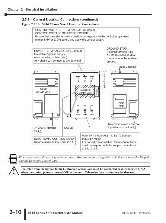
2.5.1 – General Electrical Connections (continued)Figure 2.5.1b: SR44 Chassis Size 2 Electrical Connections
CONTROL VOLTAGE TERMINALS X1, X2 (Input)CONTROL VOLTAGE SELECTOR SWITCHEnsure that the selector switch position corresponds to the control supply used(either 115V or 230V) before you apply the control supply.
POWER TERMINALS L1, L2, L3 (Input)Isolatable 3-phase supply (via contactor, isolator, etc.). Any phase can connect to any terminal.
GROUND STUDElectrical ground (PE)An M8 threaded stud forconnection to the systemground.
KEYPAD CIRCUITCARD
To remove cover, unscrew4 positions (size 2 only)
ELECTRONIC CONTROL CARDRefer to sections 2.5.2 and 2.7.1
POWER TERMINALS T1, T2, T3 (Output)Induction motor. For correct motor rotation, these connections must correspond with the supply connectionsat L1, L2, L3.
(siz
e 2
loca
tion)
(size 2 location)
CABLE
Cover(inside view)
X1,
X2
L1 L2 L3
T1 T2 T3
ElectronicControl Card
When removing and replacing the front cover, take care not to damage the cable that connects the Keypadand the Electronic Control Card.
The cable from the Keypad to the Electronic Control Card must be connected or disconnected ONLYwhen the control power is turned OFF to the unit. Otherwise the circuitry may be damaged.
SR44 Series Soft Starter User Manual 1st Ed, Rev B 07/31/20192–10

2–11
2.5.2 – Electronic Control CardFigure 2.5.2: Electronic Control Card Electrical Connections
D5 (Green LED) Indicates the presence of the control supply.
Keypad connection header.
SR44ElectronicControl Card
J7 Ribbon cableconnectorto optional SR44-RS485 Comm Card
OutputRelay
K2
OutputRelay
K1D5
(output)J8
(output)J9
(input)J10
J11
Programmable output, Relay K2.Change-over contacts that can be mapped from a selected parameter.Default = Top of Ramp
22 24 21 12 14 11 S0 S1
Programmable output, Relay K1.Change-over contacts that can be mapped from a selected parameter.Default = Run Relay
Programmable Input, Control Input 1 (S1, S0).A voltage applied to these terminals will either SET or CLEAR the parameter/bit mapped by P65.Default = Start/Stop
Programmable output Programmable output Programmable input
D5
J8ribbon cable connector J7 J9
InputJ10
22 24 21 12 14 11 S0 S1
SR44 Electronic Control Card
Connection for current transformer (CT).* J3 is factory prewired to SR44 internal CT.User-supplied external CT may be reqired for Bypass operation, depending upon other settings & parameters.* If user-supplied external CT is required, remove the two pre-connected internal CT wires from J3 and short them together. Connect the two external CT wires to J3.Connection polarity is irrelevant.
J3*
Chapter 2: Electrical Installation
SR44 Series Soft Starter User Manual1st Ed, Rev B 07/31/2019

Chapter 2: Electrical Installation
2.6 – Power Supply Connections
2.6.1 – Power Circuit Electrical SupplyPower terminals 1 (L1), 3 (L2), 5 (L3) on all units must be connected to a balanced 3-phase, 3-wireAC power supply that is within the limits specified below.
Phase sequence:
The SR44 will operate with any 3-phase rotation sequence. It is important however, to ensure
that the correct connections are made when used with a rotation sensitive load.
2.6.2 – Motor ConnectionsThe motor connects to terminals 2 (T1), 4 (T2), 6 (T3). All SR44 units will control any standard 3-phase squirrel-cage induction motor capable of operating satisfactorily when connected to themain supply with its normal load coupled.
2.6.3 – Control Circuit Electrical SupplyAll units require a separate 2-wire, single-phase supply connected to terminals X1 and X2. At theControl Voltage Selector Switch, the user can select either 115V or 230V. The diagrams in section2.5 show the location of the terminals X1 and X2 for each model of SR44.
Supply voltage must be in the range 115V (-15%, +10%) or 230V (-15%, +10%).
SR44 Power Electrical Tolerances
Nominal Supply Voltage Range
Rated Operational Voltage (Ve) 230V/460V230V -15% to 460V +10%
(usable on 208V systems down to 196V)
Rated Frequency (Hz) 50/60 +/- 2Hz
SR44 Control Power ConsumptionChassis Size Soft Starter Model Current
RatingNominal PowerConsumption
115V Fuse
230V Fuse
Fuse Type
Size 1
SR44-9 to SR44-23 up to 23A 8VA 125 mA 63mA
CCSR44-30 to SR44-44 30A & 44A 10 VA
200 mA 100 mASR44-59 to SR44-146 59A to 146A 12 VA
Size 2 SR44-174 to SR44-370 174A to 370A 18 VA
1. The control supply requires external fuse protection.2. Ensure that the control Voltage selector switch is set correctly before applying power.
The soft starter must be connected to a 3-phase power supply and a 3-phase load for proper operation.Attempted starts will result in a starter fault if either the 3-phase power or the 3-phase load is notconnected.
SR44 Series Soft Starter User Manual 1st Ed, Rev B 07/31/20192–12

2–13
2.7 – Control Card ConnectionsAll the control inputs and outputs are on the Electronic Control Card (ELC), which is mountedwithin the unit. Diagrams in section 2.5 show the location of the electronic control card.
2.7.1 – Control Inputs
2.7.2 – Control Outputs
2.8 – (Reserved for Future Use)
Control Card Inputs
Identification Description
Start/Stop12/24 VDCor115/230 VAC
Programmable Input, Control Input 1. (S1, S0)Application of a voltage between S1 and S0 will either SET (normal logic sense)
or CLEAR (inverted logic sense) the parameter mapped to by parameter P65.Removal of this voltage will either CLEAR (normal logic sense)
or SET (inverted logic sense) the parameter mapped to by parameter P65.Default setting is P52, Bit 4: Start/Stop, which is active
only when the operator selects and enters REMOTE STARTING at the keypad.The application of a voltage, as specified, between these terminals, will initiate a START.The removal of this voltage will initiate a STOP.
Control Card Outputs
Identification Description
12, 14, 11
Programmable Output, Relay K1.A bit = 1 on the parameter/bit selected by P57 makes Relay K1 ACTIVE (normal logic sense) or INACTIVE (inverted logic sense).
Default setting is P52, Bit 5: Main ContactorRelay change-over contacts:
Contact rating: 230VAC, 3A, AC1 ; 24VDC, 3A11 – Common; 12 – Normally-closed; 14 - Normally-open
22, 24, 21
Programmable Output, Relay K2.A bit = 1 on the parameter/bit selected by P59 makes Relay K2 ACTIVE (normal logic sense) or INACTIVE (inverted logic sense).
Default setting is P8, Bit 3: Top of Ramp or Full VoltsRelay change-over contacts:
Contact rating: 230VAC, 3A, AC1 ; 24VDC, 3A21 – Common; 22 – Normally-closed; 24 – Normally-open
Chapter 2: Electrical Installation
SR44 Series Soft Starter User Manual1st Ed, Rev B 07/31/2019

Chapter 2: Electrical Installation
2.9 – Typical Motor Power at Rated VoltageThe amperage values for the Soft Starter are the maximum continuous current for the model.
The motor ratings are the nearest values for the output powers of standard squirrel-cage motorsbelow the unit current rating of the SR44.
The currents (amps) quoted are for 3-phase, 4-pole motors operating on 50/60Hz power supplies.Actual currents of motors may vary by ±10% depending on size and manufacturer. Motors oflower speeds generally draw higher currents for the same rated output. Typically +10% for 6-poleor +20% for 8-pole as compared to 4 pole motors.
Motor ratings are in kiloWatts (kW) as defined by the IEC or Horsepower (HP) as defined by theAmerican “National Electrical Code” and are, where possible, normal motor sizes.
2.9.1 – Chassis Size 1 Motor Power Ratings
2.9.2 – Chassis Size 2 Motor Power Ratings
NOTE: SR44 soft starters have been discontinued. Please consider SR55 soft starters as a replacements.
SR44 Chassis Size 1 Motor Power Ratings
Model Current(Amps)
208 Volts * 230 Volts 400 Volts 460 Volts
kW HP kW HP kW HP kW HPSR44-9 9 1.5 2 2.2 3 4 5 4 5
SR44-16 16 2.2 3 3.7 5 7.5 10 7.5 10
SR44-23 23 3.75 5 6.3 7.5 11 15 11 15
SR44-30 30 5.5 7.5 7.5 10 15 20 15 20
SR44-44 44 7.5 10 11 15 22 30 22 30
SR44-59 59 11 15 16 20 30 40 32 40
SR44-72 72 15 20 20 25 37 50 40 50
SR44-85 85 18.5 25 22 30 45 60 45 60
SR44-105 105 22 30 30 40 55 75 55 75
SR44-146 146 37 50 45 60 75 100 80 100
* 208V applications are UL listed only as low as 196V.
SR44 Chassis Size 2 Motor Power Ratings
Model Amps208 Volts * 230 Volts 400 Volts 460 Volts
kW HP kW HP kW HP kW HPSR44-174 174 45 60 55 75 90 100 110 150
SR44-202 202 45 60 63 75 110 150 132 175
SR44-242 242 55 75 75 100 132 175 150 200
SR44-300 300 75 100 90 100 160 200 185 250
SR44-370 370 90 125 110 150 200 250 220 300
* 208V applications are UL listed only as low as 196V.
SR44 Series Soft Starter User Manual 1st Ed, Rev B 07/31/20192–14

2–15
2.10 – Fuse and Current Ratings2.10.1 – Full-Load Current Limit and Short-Circuit Protection
These fuses are for short circuit protection of the semiconductors, and must be mounted externallyby the user between the unit and the main power supply.
UL requires Recognized special purpose fuses (JFHR2) for the protection of semi-conductordevices, rated 700 VAC, as indicated in Table 2.10.1, be used to obtain the short circuit ratingsrequired by UL.
Suitable for use on a circuit capable of delivering not more than the RMS Symmetrical Amperesindicated in Table 2.10.1 at maximum rated operational voltage when protected by SemiconductorFuse type, Manufactured by Company and Model Number indicated in Table 2.10.1
Fuse rated 700 VAC, Amps as indicated in Table 2.10.1.
It is the responsibility of the installer and system designer/specifier to ensure that the requiredstandards or regulations are not affected by so doing.
SR44 Fuse and Current Ratings for UL Applications (Table 2.10.1)
ModelIe
(Arms)
Short CircuitCurrent (RMS)
UL Recognized JFHR2 Fuse
Bussman Model #
Mersen (formerly Ferraz)
Model #Amps
SR44-9 9
5kA
170M3110 6.9 URD 30 D08A 0063 63SR44-16 16
SR44-23 23170M3112 6.9 URD 30 D08A 0100 100
SR44-30 30
SR44-44 44 170M3114 6.9 URD 30 D08A 0160 160
SR44-59 59 170M3115 6.9 URD 30 D08A 0200 200
SR44-72 72
10 kA
170M3116 6.9 URD 30 D08A 0250 250SR44-85 85
SR44-105 105170M3119 6.9 URD 30 D08A 0400 400
SR44-146 146
SR44-174 174170M3121 6.9 URD 30 D08A 0500 500
SR44-202 202
SR44-242 242170M4114 6.9 URD 31 D08A 0500 500
SR44-300 30018 kA
SR44-370 370 170M4116 6.9 URD 31 D08A 0630 630
Chapter 2: Electrical Installation
SR44 Series Soft Starter User Manual1st Ed, Rev B 07/31/2019

Chapter 2: Electrical Installation
2.10.1 – Full-Load Current Limit and Short-Circuit Protection (continued)
2.10.2 – External Fuse RequirementsThe rating of HRC (High Rupturing Capacity) fuses for motor protection needs to be carefullyanalyzed when using a Soft Starter due to the longer start times which are involved. When highinertia loads (e.g. fans) are being started, special consideration should be given to fuse ratings dueto the extended ramping times. Most fuse manufacturers have an “extended start” or “dualelement” range of fuses intended for this type of application.
The advantage of an HRC fuse becomes evident during a fault current condition. As a result of thehigh current, large amounts of heat are created within the fuse, melting the filling of the fuse intoglass. Being an insulator, glass suppresses arc-over and breaks the circuit instantly. This behaviorminimizes the possibility of a continuing, dangerous high arc current.
For semiconductor protection fusing, refer to the table in section 2.10.1.
SR44 Fuse and Current Ratings for Non-UL Applications*
ModelIe
(Arms)
Short CircuitCurrent (RMS)
FuseBussman FWP 700V Model #
Edison E70S
Model #Amps
SR44-9 9
5kA
FWP-50B E70S50 50SR44-16 16
SR44-23 23FWP-80B E70S80 80
SR44-30 30
SR44-44 44FWP-125A E70S125 125
SR44-59 59
SR44-72 72
10 kA
FWP-200A E70S200 200SR44-85 85
SR44-105 105FWP-300A E70S300 300
SR44-146 146
SR44-174 174FWP-400A E70S400 400
SR44-202 202
SR44-242 242FWP-500A E70S500 500
SR44-300 300 18 kA
SR44-370 370 FWP-700A E70S700 700
Use these fuses with SR44 soft starters only in NON-UL applications.
SR44 Series Soft Starter User Manual 1st Ed, Rev B 07/31/20192–16

2–17
2.10.3 – Overload Current Profile and Duty Cycle AC-53a
IEC 60947-4-2 Motor Utilization Category: AC-53a (not operating in bypass mode)
IEC Index Ratings for standard operation are comprised of Rated Operational Current (Ie),Utilization Category AC-53a, Overload Current Profile (X-Tx), and Duty Cycle (F-S).
To calculate times for a lower value of current, divide the square of the next highest given currentmultiplied by its given time by the square of the required current.
For example:
• To find the time Tx for X = 2.5 x Ie , then Tx = (32 x 35) / (2.5)2 = 50 seconds.
Index Rating Example – Standard Operation(AC-53a Utilization Category per IEC 60947-4-2)
SR44 Index Ratings (for AC-53a) *
Soft Starter Model Number Ie (A)
Standard Operation
UC X-Tx F-S
SR44-9 to SR44-105 9 to 105 AC-53aAC-53a
5-43-35
99-1099-10
SR44-146 to SR44-202 146 to 202 AC-53aAC-53a
4-63-35
99-1099-10
SR44-242 to SR44-370 242 to 370 AC-53aAC-53a
4-63-35
60-360-3
* Index ratings AC-53a and AC-53b are specified by IEC standard # 60947-4-2
AC-53a Overload Current Profiles (applicable to specified Soft Starter models)
Soft StarterModel
XOverload Current(multiple of Ie)
TxDuration ofOverload (seconds)
FRatio of On-loadPeriod to Total
Load (%)
SNumber of
Operating Cyclesper Hour
SR44-9to SR44-105
3 35 99 10
5 4 99 10
SR44-146to SR44-202
3 35 99 10
4 6 99 10
SR44-242to SR44-370
3 35 60 3
4 6 60 3
9 to 105 - AC-53a: 3-35; 99-10Duty Cycle (F-S) 99-10 = 99% on-load factor - 10 cycles/hr
Overload Current Profile (X-Tx) 3-35 = 3 times rated current (Ie) for 35s
Utilization Category AC-53a = controller semiconductors provide squirrel-cage motor Start, Run, and Stop control
Rated Operational Current (Ie) 9 to 105 = controllers with Rated Operational Currents from 9A to 105A
For a 99% on-load factor and 10 standard operating cycles per hour, the unit can accommodate (3)x(Ie) for 35 seconds
Chapter 2: Electrical Installation
SR44 Series Soft Starter User Manual1st Ed, Rev B 07/31/2019

Chapter 2: Electrical Installation
2.10.4 – Overload Current Profile AC-53b
IEC 60947-4-2 Motor Utilization Category: AC-53b (operating in bypass mode)
IEC Index Ratings for bypassed operation are comprised of Rated Operational Current (Ie),Utilization Category AC-53b, Overload Current Profile (X-Tx), and OFF-time.
Index Rating Example – Bypassed Operation(AC-53b Utilization Category per IEC 60947-4-2)
SR44 Index Ratings (for AC-53b) *
Soft Starter Model Number Ie (A)
Bypassed Operation
UC X-Tx OFF-time
SR44-9 to SR44-105 9 to 105 AC-53bAC-53b
5-43-35
120120
SR44-146 to SR44-202 146 to 202 AC-53bAC-53b
4-63-35
120120
SR44-242 to SR44-370 242 to 370 AC-53bAC-53b
4-63-35
420420
* Index ratings AC-53a and AC-53b are specified by IEC standard # 60947-4-2
AC-53b Overload Current Profiles (applicable to specified Soft Starter models)
Soft Starter ModelX
Overload Current(multiple of Ie)
TxDuration ofOverload (seconds)
OFF-Time(seconds)
SR44-9to SR44-105
3 35 120
5 4 120
SR44-146to SR44-202
3 35 120
4 6 120
SR44-242to SR44-370
3 35 420
4 6 420
9 to 105 - AC-53b: 5-4; 120OFF-time 120 = 120s minimum OFF-time before restart
Overload Current Profile (X-Tx) 5-4 = 5 times rated current (Ie) for 4s
Utilization Category AC-53b = controller semiconductors provide squirrel-cage motor Start control only; bypassed for Run and Stop
Rated Operational Current (Ie) 9 to 105 = controllers with Rated Operational Currents from 9A to 105A
The unit can accommodate (5)x(Ie) for 4 seconds, but requires 120 seconds beforeinitiating any subsequent restart
SR44 Series Soft Starter User Manual 1st Ed, Rev B 07/31/20192–18

2–19
2.10.5 – Overcurrent Trip Graph
‘Current Limit’, ‘Overload Level’ and ’Overload Delay’ settings may be adjusted to limit overloadcurrents in accordance with the trip curves shown in the Overload Trip Graph.
For motors with Full Load Currents lower than the rated current of the SR44, the Overload Levelcan be adjusted using the following formula:
Overload Level = Motor FLC x 1.1 (A)
Fault current ( Motor Current x N )1 2 3 4 5 6 7 8 9 10
Overload start point(adjustable by P34 (or P93) ‡; default setting: 110%)
1000
100
10
1
0.1
0.01
P35 (or P94) ‡
‡ Parameter selected through either the primary or secondary group of value parameters
Delay = 80
Delay = 30
Delay = 10
DefaultDelay = 140
Secondsto trip
The Overload monitors only one of the phases, and the ’Current Limit’ level is only active during motorstarting.
We recommend that the control power supply be maintained between starts to ensure the integrity of theOverload, which will reset on removal of control power.
Chapter 2: Electrical Installation
SR44 Series Soft Starter User Manual1st Ed, Rev B 07/31/2019

Chapter 2: Electrical Installation
BLANKPAGE
SR44 Series Soft Starter User Manual 1st Ed, Rev B 07/31/20192–20