north atlantic right whale: designing a 1/8 scale...
TRANSCRIPT

•*•
NHU-T-05-002 C3
Hampshi
North Atlantic Right Whale: Designing a 1/8 Scale Model
Heather N. McRae
Biology: Marine and FreshwaterCollegeofLife Sciences and Agriculture
Diana J. Lewis
Mechanical EngineeringCollegeofEngineering and Physical Sciences
Rachel J. McMicken
Mechanical EngineeringCollegeof Engineering andPhysical Sciences
Project Advisor: Ken Baldwin
Ocean Projects (Tech 797) 2004-2005University ofNew Hampshire
Submitted April 22, 2005

fflKBI
RW1
t|P\
Acknowledgements
This work is the result of research sponsored in part, by the National Sea Grant CollegeProgram, NOAA, Department of Commerce, under grant #NA16RG1035 through the NewHampshire Sea Grant College Program and the UNH Marine Program.
We would like to thank our advisor Ken Baldwin for giving us the opportunity to be part ofthis project. Dr. LarryHarris, yourassistance was invaluable and appreciated very much.
We cannot thank the crew at the Ocean Engineering building enough for allowing us toconstantly ask questions, request fast service, and doing it mostly with a smile. We would nothave completed any of this project without you Paul LaVoie, AndyMcCleod, John Scott, GlennMcGillicuddy and Judson DeCew. Thank you.
Thank you to Dr. Scott Kraus for your guidance and expertise in construction of the model,Amy Knowlton for your knowledge, support, editing, and assistance, as well as the NorthAtlantic Right Whale Consortium for providing all the necessary pictures for completion of themodel and data for the paper. We are also grateful to Dr. Michael Moore for his morphometrydata collection ofthe peduncle for our model
We would also like to thank Dr. Pingguo He for your assistance with quantitativemeasurements, Bob Bowman for allowing us access to the Center for Coastal Studiesdisentanglement website, Scott Landry for answering many emails during the early stages of theproject, and our Mends, who have been supportive and understanding that our lives have beenconsumed by 'the whale9.
n

LIST OF FIGURES.- 2
ABSTRACT 1
1. INTRODUCTION TO EUBALAENA GLACIALIS. 2
2. BACKGROUND ON EUBALAENA GLACIALIS . . 3
2a. Classification 32b. Population Status 3i. Whaling History 3
2c. Distribution and Ecology 4
i. Habitat 4
ii. Food andfeeding 42d. Life History 5
. /. Behavior..... . 5
ii. Growth and Reproduction 52e. Population Decline 62f. Current Status 62g. Research methods 7
3. STEPS TO DESIGNING A SCALE MODEL . 7
3a. Scaling 73b. Modeling based on scale 10
/. Data acquisition 103c. Design concepts 123d. Generating the final design 13
4. GENERATION OF THE MODEL (NOT INCLUDING PROPULSION DESIGN) 15
4a. The model stepby step 15r. sectionscut andglued together. 15ii. ballasting holes 15Hi smoothingofbody.... '. 15iv. epoxy covering 16v. neopreneoverlay 16vL insertingthe Ballast...* 16
4b. Problems associated with the model 17
5. PROPULSION STRUCTURE OF MODEL 18
5a. Design 18
/. strength. 20ii. rotationability 20
6. FISHING GEAR....... . . . 20
6a. Types of gear 206b. Choosing to model gillnet or lobster pot gear 21
/. Design 21
7. DATA ACQUISITION . ...22
7a. Dataobservation design and construction 227b. Utilizing a camerafor observation 227c. Datasheets 25
8. RESULTS . 25
9. DISCUSSION i 26
in

10. REFERENCES . 28
APPENDIX 30
Appenddc 1: Whale fact sheet. 31
Appendix 2: Baleen whale head structure and filter feeding 32Appendix 3: Reynolds Scaling Calculations 32Appendix 3: Reynolds Scaling Calculations 33Appenddc 4: External Morphometrics 35Appendix 5: Calculations for the design of the peduncle 36
p» Appendix 6: Body cross section measurements 37Appendix 7: Towing Structure Calculations 38Error! Objects cannot be created from editing field codes.Appendix 8: Purchase estimates forCamera 3gAppenddc 8: Purchase estimates for Camera 39Appenddc 9: Datasheet 41Appenddc 10: Tow on April 22,2005 42
W\
•Sn
jp&)
Fpfl
IV

Abstract
This construction ofthe 1/8* scale model ofa North Atlantic Right whale is the first knownscalemodel made to simulateentanglement. This scale model is now a resource and tool for scientists,government, legislation, and education. The construction of the scale model helps to provideinformation on the building of such scale items. The scale model provides an opportunity togather qualitative data for enhancing the understanding of the entanglement ofmarine mammals.It was shown that a scaled model of a North Atlantic right whale can be built and survivesubmersion in water for over a period of 8 hours. Although some materials should not be used infuture model construction, the overall design mimics shape, size, and characteristics. It wasestimated that the scale model would require approximately 300 lbs as weight, however it took296 lbs to make the scale model neutrally buoyant. Initial runs yielded problems areas of themodel, namely the pipe and the way in which it is festened inside the whale. However, initialruns also found that the scaled gear line ripped through the scale model whichwas traveling at 2knots (0.25 m/s), which is half the typical traveling speed ofa right whale. It was found that thismodel is a prototype for future models that will aide in the knowledge of entanglement,particularly insightinto how they occur.

pq
BH
List ofFigures
Figure 1: Scale model length vs. Velocity (whale velocity of0.5m/s) 9
Figure 2: Photographs used in the design ofthe NARW model from the Right Whale
Consortium at the New England Aquarium 11
Figure 3: Giant Whale Caliper (GWC) 11
Figure 4: Full body belly-up 13
Figure 5: Body curvature ofthe NARW 14
Figure 6: Body cross sections... 14
Figure 7: Removal ofEg #1004 14
Figure 8: Peduncle design 14
Figure 9: Step by step process ofthe model construction 15
Figure 10
Figure 11
Figure 12
Figure 13
Figure 14
Figure 15
Figure 16
Figure 17
Figure 18
Neoprene application 16
Lead shot application. .17
The pregnant whale versus the slimmed whale 18
Tow structures 19
Unistrut, bolt and nut 19
Unistrut corner connectors 19
Gillnet and Pot-gear , 21
Critical entanglement area 23
Camera housing attachment 24

1. Introduction to Eubalaena glacialis
There are approximately 350 individuals in the western North Atlantic right whalepopulation (North Atlantic Right Whale Consortium). As a criticallyendangered species, there ishigh concern about the interaction between right whales and fishing gear. This coastal species9habitat ranges from wintering and calving grounds in coastal waters of the southeastern UnitedStates to summer feeding and nursery grounds in New England waters and northward to the Bayof Fundy. These habitat areas are significant to commercial fisherman as well as commercialshipping lanes. It is this interaction between human, technology, and cetacean that causesignificant human-induced mortality thus declining reproductive rates that affect the populationgrowth (Kraus et aL 2001, Pettis et al 2005).
The population growth of the North Atlantic Right whale {Eubalaena glacialis) isthreatened by increasing instances ofhuman-induced mortality (Kozuck et al. 2005, Kraus 1990,Kraus and Knowlton 2001, Moore 2005, Pettis 2004). Including ship strikes and entanglements,human-induced mortality accounted for four fatalities between February 2004 and February 2005off the Atlantic coast (North Atlantic Right Whale Consortium) 3 others - 2 of unknown causeand 1 live stranded neonate during that time frame. Any part of fishing gear has the potential toentangle a whale, and ranks second to ship strikes for known causes ofmortality (Kozuck et al,Kraus, 1990).
There is more known on ship strike mortality than entanglements due to thecharacteristics of mortality type. Whales struck by ships are more likely to wash ashore or beseen, as entanglements oftenoccur fer offshore and the whale is likely to sinkor drift to the openocean (Moore et al 2005). Eubalaena glacialis is known to be vulnerable to fishing gearentanglement along the Atlantic coast oftheUnited States (Kraus, 1990).
Moore et al. (2005) reviewed necropsy reports of thirty Right whale mortalities from1970 to 2002 and found that human induced trauma from ship collisions and fishing gearentanglement were the primary causes ofdeath. It is likely that there is a foraging behavior trendbetween the North Atlantic Right whale and entanglement incidents (Kozuck et aL). Of thirty-one events studied between 1993 and 2002 by Kozuck et al; twenty- four involved the mouthwhere five were responsible for the death of the whale (Kozuck et al). With approximately 350individuals in the North Atlantic Right whale population (North Atlantic Right WhaleConsortium) each death is critical to the overall population.
Mitigation plans to alleviate ship strikes have already been established, such as movingthe shipping lanes in the Bay of Fundy during months when right whales are present as well asthe Mandatory Ship Reporting System established in 1999 (Silber et al 2002). By modeling theprocess of entanglement it is possible to extend that knowledge to the professional communitiesof cetacean biologists as well as fisherman. This understanding may lead to potential gearmodifications and fishery standards. This project aims to quantify the interaction between theNorthAtlantic Right whale and fishing gear viaa scaled model
It is imperative that the interaction between right whales and fishing gear is modeled in acontrolled environment; specifically, using scale models. By designing and building a scalemodel of a North Atlantic right whale, it may be possible to look at how entanglements occur.By observing the average traveling speed of a right whale (0.5 m/s) and pushing it (via a towtank) into scaled gear, it may be possible to determine the effect the gear has on skin surfaces, aswell as the modes by which lines become entangled. A scale model for the purpose of testingentanglement interactions has never been done. This project will help to lay the groundwork for

Wffl
WD
API
future model design, construction, and testing. Through testing, valuable information on the wayin which line interacts with right whales should be obtained, helping to understand how rightwhales become entangled.
2. Background on Eubalaena glacialis
Eubalaena glacialis was listed as an endangered species on June 2, 1970 for the entiretyof its coastal habitat along the Eastern seaboard of the United States (US Fish and WildlifeService). The scientific name translated is 'true whale of the ice' which no longer represents thiscoastal species (Clapham 2004). The common name, the North Atlantic right whale, was givenbecause they were the 'right' whale to hunt. Their characteristic oblong body has no dorsal fin,fiat paddle-like flippers, and a head that is one-third of the body; this is often covered incallosities, or roughened skin patches much like human fecial hair. Today, these marinemammals have an estimated population of approximately 300 individuals and are considered acritically endangered species (Knowlton et al 1994, US Fishand Wildlife Service).
2a. Classification
Baleen whales (Mysticeti) are one of two Cetacean sub-orders (Appendix 1: Right whalefeet sheet). The toothed whales (Odontoceti) rely on the use of teeth, while the Baleen whalesfeed on rice sized copepods by a process of highly specialized filter-feeding. They have what iscalled baleen, a series of keratin plates attached to the gumof the upperjaw that are smooth onthe outside and fringed on the inner side of the mouth. Skeletal differences occur that definethese two species as well as the two blowholes of a baleen whale versus the one of a toothedwhale (Encyclopedia of Marine Mammals - pg. 62). Generally, the size of the baleen whale islarger than the toothed whales. Life histories include long migrations for some species, comingclose to the coast, but having a primarily openocean habitat. The right whales are one of fourfamilies in the Mysticetes; right whales (Neobalaenidae), pygmy right whales (Neobalinidae),gray whales (Eschrichtiidae), and the rorquals (Balaenopteridae). The right whales aredistinguishable due to their narrow and long baleen plates, highly arched upper jaw, large headwhich is one-third of body length, no dorsal fin, and two to five deep creases rather than thetypical ventral grooves of Baleen whales. There are two Families of right whale, the NorthAtlantic rightwhale and the Southern rightwhale.
2b. Population Status
L Whaling History
Commercial whaling in the North Atlantic began during the 11th century in the Bay ofBiscay by the Basque whalers (Aguilar 1986). Thehunt for the right whale spread to Labrador inthe 1530's andthento NewEngland bythe 1600's. Although not the most desirable ofthe huntedwhales (in regards to the Sperm Whale for oil), the right whale was the easiest to hunt. Rightwhales were oftenclose to a beach, visible to the land-based hunters and provided an extensivesupply of blubber. Right whales move slowly through the water and float once killed, making iteasy for a whaler to spot and hunt the whale. The blubber or fat of a right whale comprisesapproximately 40 percent of the body weight, which can reach upwards of 100 tons (NewBedford Whaling Museum). Both the blubber and baleen (food filtering mechanism in themouth) provide a plethora of materials for products such as soap, lamp oil, corset stays, and

hairbrush bristles (New Bedford Whaling Museum). The 1860's marked the technologicaladvancement to mechanized, steam-powered boats from the old traditional sail and oar poweredwhaleboats introduced a new era ofwhaling. This new process was a succession ofrelentless andefficient technology that not only increased efficiency by volume which enabled the whalers tohunt even blue whales and finbacks-the largest species, which, by reason of their speed in thewater, had eluded all previous hunting technologies (New Bedford Whaling Museum). TheInternational Whaling Commission (IWC) was established in 1949 to monitor populationabundance utilizing an expert Scientific Committee. However, the IWC did not use enforcementand in 1972 the United Nations asked for a cessation of whaling while Congress passes theEndangered Species Act. A general moratorium was adopted by the IWC in 1982 (which tookeffect in 1987) to prevent extinction of many cetacean species, including the criticallyendangered North Atlantic right whale (Twiss and Reeves 1999). Currently, the IWC hasassigned "Protected Stock" status to all stocks of the North Atlantic right whale (IWC). Thecatch quota istherefore set at zero for all signatory nations of the IWC. The North Atlantic rightwhale experienced the longest hunting history of any large whale species until the moratorium in1982. Today, the biggest threat the species feces is that of human-induced mortality from shipstrikes and entanglement.
2c. Distributionand Ecology
L Habitat
Historically, right whales occurred in all of the world's oceans from the temperate to sub-artic regions. The distribution of this species relies heavily on the distribution of theirzooplankton prey and their preference for shallow coastal areas (Winn et al 1986). The NorthAtlantic right whale population ranges from wintering and calving grounds in coastal waters ofthe southeastern United States to summer feeding and nursery grounds in New England watersand northward to the Bay of Fundy and the Scotian Shelf (Mitchell et al 1986). Knowlton et al(1992) reported several long-distance movements as far north as Newfoundland, the LabradorBasin, and southeast ofGreenland. In both the North Atlantic and the Southern Hemisphere notall reproductively active females return each year to the calving grounds (Kraus et al 1986;Payne, 1986). The calving grounds extend from southern Georgia to northern Florida during themonths of December through March (Encyclopedia of Marine Mammals - pg. 810). Researchsuggests the existence of six major habitats or congregation areas for western NARW; these arethe coastal waters of the southeastern United States, the Great South Channel, GeorgesBank/Gulf of Maine, Cape Cod and Massachusetts Bays, the Bay of Fundy, and the ScotianShelf(Waring et al2003). These designated areas were created as critical habitats for the westernstock of the right whales due to their importance to the reproductive and feeding activities of thespecies (Kraus andKenney 1991).
it Food and feeding
Although Baleen whales include the largest living animals on earth they are primarilycarnivorous and feed onzooplankton or small fish. The North Atlantic right whale feeds ontinyplankton called copepods (Clapham 2004). The filter-feeding process by which these whalesfeed ishighly specialized and requires three basic features: a flow of water that brings prey to themouth, a filter that allows water to pass through but collects food, and a means to remove thefood and send it to the stomach (Encyclopedia of Marine Mammals pg. 66). The right whale isconsidered a skimmer, in that it skims the surface of the water with its mouth open allowing a
4

flow ofwater through their baleen plates and capturing copepods as its food resource (Appendix2: Baleen whale head structure and filter feeding). The inner and longer border of each plateincludes fringed hairs forming the filter. There are as many as 270 plates on each side of the topjaw (almost 600 total) that reach a length of approximately 2.4 m or 8 feet (Conservation andManagement of Marine Mammals). The whales will use their tongue to remove the copepodswhile forcing water through the plates off the fringe and then they will swallow their prey. Rightwhales can feed at both the surface waters (skim-feeding) as well as near the ocean floordepending on the season and food resource availability. The whales eat an average of 750kilograms of copepods each day, consuming 500,000 calories (the equivalent to 1650hamburgers). Mayo and Marx (1990) suggested that right whales locate and utilize only densepatches of zooplankton for feeding efficiency. Characteristic of the spring, summer, and fellhabitats are these dense patches of zooplankton (Kenney et al 1986,1995). Kenney et al (1995)reported a long-term increase in sighting rates within one feeding area of the western NorthAtlantic (Great South Channel) of 3.8% per year between 1979 and 1989, but extrapolation ofthis rate to the entire stock was inappropriate. These dense zooplankton patches may be causedby a process called upwelling which relies on coolnutrient rich water being forced to the surfacewhere depths of 100-200 m adjacent to steeply sloping bottomtopography drive the cool waterupwards (Winn et al 1986).
2d. Life History
L Behavior
Sound production is thought to be used for communication, display or even establishmentof territory and is heavily used by males within the baleen family. Right whales produce lowfrequency moans and pulses and also utilize a gunshot sound. Most sound is produced at anacoustic energy below 500 Hz. This gunshot sound is thought to be associated with mating oreven to stun food. It is a short intense sound mimicking that ofa gunshot. Researchers observedboth lone and grouped males, where no observations of females making the gunshot sound weremade. Right whales are typically solitary, however observations of social groups in the Bay ofFundy have documented 2-20+ whales in surface active groups. Baleen whales, such as the rightwhale have some of the longest documented migrations where they calve in the warmer tropicalwaters and mate and feed in the cold nutrient rich waters, such as the Bay of Fundy. Rightwhales are also known to complete aerial behaviors such as breaching, lobtailing, and slappingthe waters surface with their flipper. Each behavior produces a loud sound but the reasoningbehind them is still unknown.
ii Growth and Reproduction
The youngest mature female in the western North Atlantic was age 4 and calved at age 5.This data is known from the right whale catalog used in the identification of individuals withinthe population. However, the typical age of maturity/calving is around 9/10 years of age. Thegrowth of these mammals is rapid and body weight of the young (known as calves) doubleswithin the first year. After the first year, growth is dependant on food availability and feedingsuccess. It is thought that right whales reach sexual maturity at body lengths of 13-16m(Encyclopedia of Marine Mammals - pg 811). The longevity of whales is unknown, as mostdeaths (that we know of) occur from anthropogenic influences. The oldest known right whalewas approximately 70 years old, but died due to a ship strike. Thus, the longevity is trulyunknown. During their life, females average 2-3 years between calving. Gestation lasts

approximately one year as does weaning. Milk weaned to young is mostly fat and has been saidto have the consistency ofcottage cheese.
Relative to other populations (Eubalaenaaustralis), the growth and recovery ofthe NorthAtlantic right whale is slow, seen in the increase of the calving interval between 1985 and 1997from 3.33 to 5.36 years (Kraus et al. ?) The number of calves born each year varies and from1990 to 2004 there were an average of 13 calves per season with an average calving interval of5.0 years (Right Whale Consortium unpublished data). Currently, there is no prediction to as thenumber of calves that will be born per season or the calving interval of the species. In contrast,the Southern species (Eubalaena australis) has a reproductive rate double that of the northernspecies (Knowlton et al 1994; Best et al, 2001; Kraus et al, 2001).
2e. Population Decline
The decline in the North Atlantic right whale population is unknownbut thought to be dueto several reasons. Commercial whaling reduced the North Atlantic stock of the right whalesfrom around 12,000 in the 11th century to nearly 300 individuals in the population by the 21stcentury (Waldick et aL 2002). Populations with low numbers face the probability of losinggenetic variability amongst the population which can be detrimental and reduce the ability of thatpopulation to adapt or respond to changes in the environment (Waldick et aL 2002). The NorthAtlantic population varies greatly from their Southern counterpart (Eubalaena australis) whichhas greater genetic diversity, a higher birthing rate, but also a larger population. Walkdick et aL(2002) found that the low genetic variability in the NorthAtlantic right whale predates the mostsevere population decline in the 18th century. However, with already low numbers thepopulation is more susceptible to human-induced mortality such as ship strikes andentanglement, which is tied to foraging and migration habitats along the easternseaboard. NorthAtlantic right whales show a 7% incidence rate of having scars from ship propellers and a 60%incidence rate of entanglement scars (Waring 1999). However, there is a high rate of shippropeller wounds found on stranded whales which indicates that many or most interactionsbetween ships and a whale are fetal (Kraus 1990). Including ship strikes and entanglements,human-induced mortality accounted for six fatalities between February 2004 and February 2005off the Atlantic coast (North Atlantic Right Whale Consortium). Unlike slrip strikes,entanglements are less frequently observed as the whales are more likely to float and moveoffshore with ocean currents (Moore et al 2005). Anthropogenic induced mortality has aprofound effect on the population of the North Atlantic right whale but does not necessarilyaccount for the reason why this population has such low numbers. Otherpotential factors couldinclude pollution, habitat destruction, and potentially whale watching but none have shown tohave profound effects on the population (Marine Fisheries Review). With a reduction of twofemale deaths per year (in a population of 150 females) a positive population growth can beachieved(Fujiwara and Caswell2001).
2f. Current StatusTheNorthAtlantic right whale has been protected from commercial whaling for more than
60 years, but their population remains low. The Southern right whales, in contrast, have shownsigns of recovery over the past 20 years (Best, 1990; Payne et aL 1990). The populations of E.glacialis are spread across the North Atlantic and the North Pacific while Eubalaena australisroams the waters of the Southern Hemisphere. Considered the rarest of the baleen whale species,the North Atlantic right whale (of the western Atlantic population) has no more than 300

individuals (Knowlton et al. 1994). Using photographic identification data Knowlton et al (1994)estimated the annual population growth rate from 1986 to 1992 was at 2.5 percent. The SouthernAtlantic right whales are a thriving population with approximately 7,000 individuals (MarineFisheries Review).
There is very little data available on natural mortality of this species due to the nature ofnatural mortality. Kraus (1990) found an average natural mortality rate of 17% per year in first-year offspring. However, those whales entering their second through fourth year had an averagenatural mortality rate of 3% per year. More information is known on anthropogenic inducedmortality such as entanglement and ship strikes.
2g. Research methods
To date there have been no documented attempts at modeling a right whale and simulatingthe process of entanglement. Early methods included gross anatomical descriptions or publishedhunting records. The use of logbooks, newspapers, and commercial records began to beinvestigated during the 1970's. The 1980's discoveries of right whale habitat areas gave way tolarger conservation and research programs. These field studies utilize ships and planes forsurveys and analysis of behaviors and distribution. Photography of individuals has allowed theidentification of individuals and valuable life history data. There is research every day thatincludes new methods, but researchers are yet to model the most threatened cetacean species.Potentially, the modeling of any animal, especially a marine mammal include many variables, allof which cannot be tested (as of yet) at one time. Recognizing this absence of a lab model andtesting, the scale model of the North Atlantic right whale will help lead the way to improvedunderstanding of the entanglement scenario and conservation of this critically endangered marinemammal i
3. Steps to Designing a Scale Model
3a. Scaling
A mature right whale is 40-50 feet in length. Based on facility constraint, we must scalethe dimensions of the scale model to fit the tow tank we willneed for testing. The tow tank is 8feet deep, 12 feet wide, and approximately 100 feet long. The aluminum carriage is 12 feet wide(to fit tank), 75 inches long, and 12 inches deep. Thusa full size model ofa North Atlantic rightwhale would use halfof the two tank. Due to this, the model is scaled to a smaller size to allowtesting in the two tank.
When scaling, there are three concepts that need to be considered: geometric similarity,kinematic similarity, and dynamic similarity. Models are designed to mimic as much of theoriginal as allowed. The necessity for geometric similarity is based on size comparison.Kinematic similarity uses the scaling of velocity, or fluid flow. Ifyou add dynamic similarity to amodel, the forces will be scaled, however, you cannot scale both kinematic and dynamic at thesame timewhenthe model is geometrically scaled. Thus, the two most importantshouldbe used,which varies with model use and testing.
Two types of scaling result from this distinction between dynamic and kinematic scaling.Froude scaling is used to scale dynamically: it scales to equate inertial and gravitational forces.Reynolds scaling is used to scale kinematically: it is used for immersed objects, where no surfaceinteractionoccurs and the most importantfactor is viscosity.

The Froude number is a ratio of inertial forces to gravitational forces. Froude scaling isused when gravitational forces predominate, such as waves that are created on the surface ofthewater. It equates the Froude Number of the scaled system to the original system. The Froudenumber is
Fr =V2/(gD) (1)where V is the velocity, g is the gravitational constant, and D is the diameter of the object. Toscale using the Froude number, equate the Froude number for the model and the prototype(whale). The gravitational constant will drop out, leaving Vp2/ Dp = Vm2/Dm. Because thediameter ofthe model is specified, and there is a need to know how fast the scale model has to betowed at that diameter, the equation becomes
Vm =VpV(Dn/Dp). (2)This equation showsthat as the diameter ofthe scale model becomes smaller, the velocity ofthewhale decreases by its square.
The Reynolds number measures the relative importance of inertial (pressure) and viscous(friction) stresses on a submerged object when determining flow pattern. Fluid particles resistacceleration and deceleration; this effect is the inertial effect. Not only do the particles want tokeep moving, they also want to stay together and resist the shear and formation of velocitygradients. This scaling allows us to study flows and forces on a submerged object. The Reynoldsnumber is
Re = VD/u (3)where V is the velocity, D is the diameter, and u is the viscosity. To scale using the Reynoldsnumber, equate the two Reynolds numbers of the prototype and scale model to yieldVpDp/up=VmDm/um. Because the tests are in the same fluid as the prototype (the actual whale),the viscosities are the same and drop out ofthe equation, which reduces to VpDp = V„Dm. Witheither scaling regime, the model scale factor influences the model velocity, and vice versa. Thevelocityneedsto be calculated for the chosen scale factor. Therefore, the equation becomes
Vm= VpDi/DnL (4)Notice as the scale model diameter decreases, the velocity of the scale model increases. This isopposite ofthe effect ofFroude scaling, when the scale model velocity decreases when the scalemodel size decreases.
0.000 2.000 4.000 6.000 8.000 10.000 12.000 14.000 16.000
Length (m)
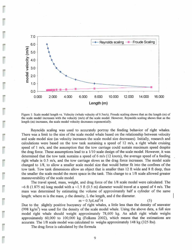
Figure 1: Scale model length vs. Velocity (whale velocity of 0.5m/s). Froude scaling shows that as the length (m) ofthe scale model increases with the velocity (m/s) of the scale model. However, Reynolds scaling shows that as thelength (m) increases, the scale model velocity decreases exponentially.
Reynolds scaling was used to accurately portray the feeding behavior of right whales.There was a limit to the size of the scale model whale based on the relationship between velocityand scale model size (as velocity increases the scale model size decreases). Initially, research andcalculations were based on the tow tank sustaining a speed of 12 m/s, a right whale cruisingspeed of 1 m/s, and the assumption that the tow carriage could sustain maximum speed despitethe drag force. These assumptions lead to a 1/10 scale design of the scale model. However, it wasdetermined that the tow tank sustains a speed of 6 m/s (12 knots), the average speed of a feedingright whale is 0.5 m/s, and the tow carriage slows as the drag force increases. The model scalechanged to 1/8, to allow a smaller scale model size that would better fit into the confines of thetow tank. Tow tank dimensions allow an object that is smaller than 12 ft wide and 8 ft deep, thusthe smaller the scale model the more space in the tank. This change to a 1/8 scale allowed greatermaneuverability of the scale model.
The travel speed, mass, weight, and drag force of the 1/8 scale model were calculated. The~6 ft (1.875 m) long model with a ~1.5 ft (0.5 m) diameter would travel at a speed of 4 m/s. Themass was determined by estimating the volume of approximately half a cylinder of the samelength: where m is the mass, p the density, L the length, and d the diameter.
m= 0.5pL7td2/4 (5)Due to the slightly positive buoyancy of right whales, a little less than the density of seawater(998 kg/m3) was used for the density of the scale model whale. Using the above data, a full sizemodel right whale should weight approximately 78,600 kg. An adult right whale weighsapproximately 60,000 to 100,000 kg (Folkens 2002), which means that the estimations areaccurate. The 1/8 scale model was calculated to weighs approximately 148 kg (325 lbs).
The drag force is calculated by the formula

Fdrag=l/2CpAv2, (6)where A is the area of the surface perpendicular to the flow and C is a drag coefficientbased ongeometry. The drag force is equal for all scale sizesof the whale. This occurs becausedrag forcedepends on the square of both velocity and diameter of the body while Reynolds scaling makesthe velocity and diameter proportional despite the size. The drag was calculated based on asphere, to rnimic that of a whale with its mouth closed. The drag force was calculated at 170 N(Appendix 3: Complete Scaling Calculations).
Material availability was accommodated for in the completed design of the scale model.The design called for foam cross sections. Because the foam used was 3.5 in thick (Section B),the scale was adjusted to 1/7.865. This adjustment did not significantly change the calculatedweight or towing speed. The speed desired to best mimic a traveling right whale was changedfrom 4 m/s to 4.06 m/s. The weight also increased by five pounds (325 lbs to 330 lbs). The finaldesign ofthe scale model relied on the acquired data ofright whale biology and anatomy.
3b. Modeling based on scale
L Data acquisition
The majority of the North Atlantic right whale model design derived from photographs.Survey, entanglement, and necropsy photographs provided a strong background to design theshape and structure of the body. Photographs were provided by the North AtlanticRight WhaleConsortium (Figure 2: Photographs used in the design of the NARW model). Necropsy reportsas well as field measurements of a deceased right whale helped to add quantitative data to thedesign shape. The North Atlantic Right Whale Consortium provided the necropsy report for Eg#1004 and Dr. Michael Moore provided his 2005 publication; Morphometry, gross morphologyand available histopathology in Northwest Atlantic right whale (Eubalaena glacialis) mortalities(1970 to 2002). Dr. Moore also provided specific peduncle measurements from Right whale#2301 found dead on Ship Shoal Island, Virginia March 3, 2005 (Appendix 4: ExternalMorphometries). These data allow a realistic two-dimensional cross section to be modeled withknown width, bottom arc radius, and girth measurements. However, photographs are not alwaystaken as a design drawing would prefer.
Engineers use three views in a design sketch; top, side, and bottom. These three viewsallow for model generation. Based on the photographs provided, the frontal view of a NorthAtlantic right whale was extremely hard to come by. Profile views in a photograph are oftentaken at an angle to encompass the entirety of a whale in a camera lens. Boats also view whalesat angles, and not head on, thus most photographs would be angled. Unfortunately, whenphotographs are taken the angles at which they are taken are not determined nor do they containa coordinate system for reference. Thus, whales photographed in their natural habitat provideuseful information for identification, behavior, and shape. Using photographs of beached whales(deceased) an opposite problem occurs. These views are distorted by gravity on land (versuswater), the weight of the whale in sand, and the bloating (gas) associated with deceased animals.Thus, photographs were used as references for shape (qualitative data) while the necropsy reportsand field measurements provided the necessary information to determine the distances betweenanatomical features (quantitative).
10

•
l-i T_. -
D
Figure 2: Photographs used from the Right Whale Consortium at the New England Aquarium. Figure A -Drepresent the modeling of the head and rostrum. A. A NARW spyhopping and demonstrating a strait dorsal view ofthe head and rostrum. B. A NARW at the surface, notice the flatness at tlic tip of the head. C. The removed head ofStumpy. Here demonstrating the curvature or tlic mouth. D. A dorsal view of the rostrum for model design. E. Usedfor full body design.
11
Figure 3: Giant Whale Caliper (GWC). The GWCwas designed to achieve accurate measurementsalong the body length of a beached whale. Theobtained data would help to design a more accuratemodel of a North Atlantic right whale. Althoughthe GWC does not compensate for bloating ordeterioration, the data would provide verificationof size and shape.
IS
A second alternative for obtaining quantitative measurements was determined. The GiantWhale Caliper (GWC) was designed as a tool to determine the height and width at points alongthe length of the body (Figure 3: Giant Whale Caliper). The GWC would (and could) only beused on beached whales. Made of adjustable rods, the GWC would also have height and widthmarkings for data collection. It was thought that the measurements would provide data (incombination with photographs and necropsy reports) to better determine the design of a rightwhale model. The opportunity for such use is limited due to the short time interval prior to abeached whale being removed. Several opportunities arose for the construction and use of theGWC, however, due to timing the GWC was never implemented.
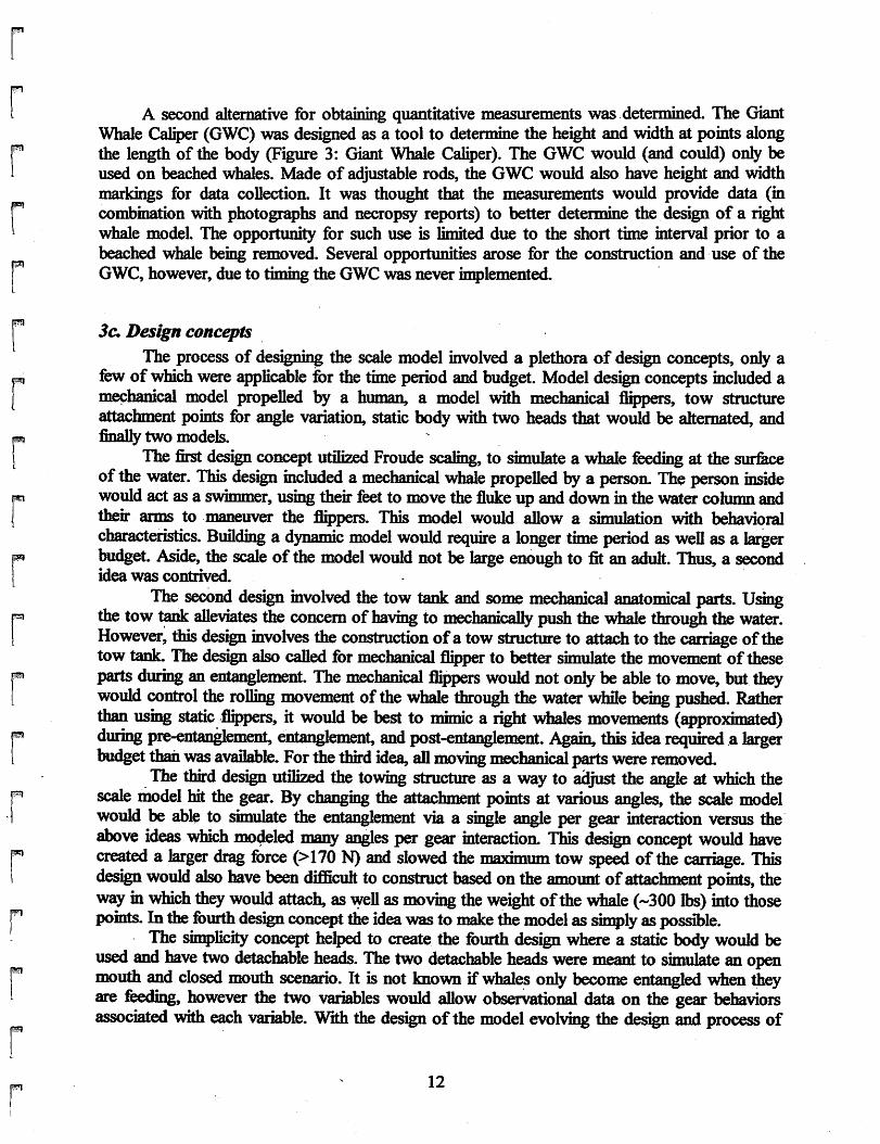
3c, Design conceptsThe process of designing the scale model involved a plethora of design concepts, only a
few of which were applicable for the time period and budget. Model design concepts included amechanical model propelled by a human, a model with mechanical flippers, tow structureattachment points for angle variation, static body with two heads that would be alternated, andfinally two models.
The first design concept utilized Froude scaling, to simulate a whale feeding at the surfaceof the water. This design included a mechanical whale propelled by a person. The person insidewould act asa swimmer, using their feet to move the fluke up and down in the water column andtheir arms to maneuver the flippers. This model would allow a simulation with behavioralcharacteristics. Building a dynamic model would require a longer time period as well asa largerbudget. Aside, the scale of the model would not be large enough to fit an adult. Thus, a secondidea was contrived.
The second design involved the tow tank and some mechanical anatomical parts. Usingthe tow tank alleviates the concern of having to mechanically push the whale through the water.However, this design involves the construction ofa tow structure to attach to the carriage ofthetow tank. The design also called for mechanical flipper to better simulate the movement oftheseparts during an entanglement. The mechanical flippers would not onlybe able to move, but theywould control the rolling movement of the whale through the water while being pushed. Ratherthan using static flippers, it would be best to mimic a right whales movements (approximated)during pre-entanglement, entanglement, and post-entanglement. Again, this idea required a largerbudget than was available. For thethird idea, all moving mechanical parts were removed.
The third design utilized the towing structure as a way to adjust the angle at which thescale model hit the gear. By changing the attachment points at various angles, the scale modelwould be able to simulate the entanglement via a single angle per gear interaction versus theabove ideas which modeled many angles per gear interaction. This design concept would havecreated a larger drag force (>170 N) and slowed the maximum tow speed of the carriage. Thisdesign would also have been difficult to construct based onthe amount ofattachment points, thewayin which theywould attach, aswell as moving theweight ofthe whale (-300 lbs) into thosepoints. In the fourth design concept theidea wasto make the model as simply aspossible.
The simplicity concept helped to create the fourth design where a static body would beused and have two detachable heads. The two detachable heads were meant to simulate an openmouth and closed mouth scenario. It is not known if whales only become entangled when theyare feeding, however the two variables would allow observational data on the gear behaviorsassociated with each variable. With the design of the model evolving the design and process of
12

"
the detachable heads was questionable. With a removable head the main concern was to not havea seam. Seams on a model of a seamless animal provide more potential areas of entanglement.Also, the question arose on how to attach heads when using foam as many materials do not stickto foam or withstand the prolonged exposure to water. The fifth concept derived from this model.
Desiring both the open and closed mouth models, the fifth design concept included twoseparate scale models. There would be no seam along the body for potential gear entanglementthat may not exist in the natural environment, while also alleviating the pressure of detaching ahead on a -300 lb scale model. The closed mouth model was begun prior to the open mouth forseveral reasons. First, the closed mouth model was easier to reproduce based on the availabilityof photographs and data. Second, a closed mouth does not require simulated baleen to be present.Baleen, the filter for the right whales' food would have been another project to create. Givenmore project time and consideration to the potential ways in which to model baleen, the openmouth model would be invaluable. However, completing a closed mouth design is alsoinvaluable as it provides the first attempt to build a scale model of a right whale for entanglementsimulation.
3d. Generating thefinal designThe final design of the North Atlantic right whale model was constructed via cross-
sections derived from calculated intervals along a right whale body length. The data for scaleddimensions was provided in necropsy reports and field measurements of Eg #1004 and Eg#2301. Three sections were determined for the scale model design; head, body, and peduncle.
The head section dimensions were determined by using photographs and cross-referencingquantitative data. The photographs from Clapham (2004) demonstrated several cetaceanbehaviors, where the head is clearly defined. The body, unlike the head does not have a clearlydefined shape.
The shape of the body utilized varyinganatomical photographs of Eg # 1004. Thelength of the design was found using aphotograph of a full view belly up carcass(Figure 4:Full body belly-up of Eg #1004).Photographs of body features like the curvatureof a whales belly typically derive from floatingcarcasses (Figure 5: Body curvature of theNARW) or the curvature of the head originatefrom beached and decapitated carcasses (Figure5: Body curvature of the NARW). A finalsketch of the body shaping includes foursections (Figure 6: Body cross sections). Thepoint at which the body becomes the pedunclewas determined by angled profiles of a beachedwhale (Figure 7: Removal of Eg #1004).
Figure 4: Full body belly-up of Eg #1004. This photoprovides tlic length of body measurement.
13

•
!
r
^^^^PPI ^^^fc-Wj' «^T^L, "is*.
r j
HbL.^ .^T^rn -lA -' i A.
Figure 5: Body curvature of the NARW. A. Belly-up deceased whale. This view provides the curvature to producethe underside of the model. B. Arc of Eg #1004 head. This gives a great view to how the body curves.
Figure 6: Body cross sections. Thefinal drawing of the body shape based
on photographs and morphometry.
Figure 7: Removal of Eg #1004.
/' 2^l-(aUh)
Figure 8: Peduncle design. This figure demonstrates the process ofI converting circumferences into the elliptical shape of the peduncle.
Equation 1: Ellipse equation. This was used to determine the shape ofthe peduncle.
The peduncle measurements from the field ensured an accurate representation of size on themodel. The peduncle girths were measured at 20 cm increments from the fluke insertion (Figure7: Removal of Eg #1004). It was assumed the peduncle was shaped like an ellipse. Using theequations for an ellipse, the girth measurements (P), width dimensions (b) gave height (a)(Figure 8: Peduncle design). The calculations yielded the elliptical shape of the peduncle(Appendix 5: Calculations for the design of the peduncle). Completion of dimension calculationsrequired scaling the design to the preferred scale of 1/7.865 (Appendix 6: Body cross sectionmeasurements).
14

-
•
I
4. Generation of the Model (not including propulsion design)
4a. The model step by step
The scale model of the North Atlantic right whale was generated using foam board (3.5 inthick) cut to the design of the calculated 18 cross-sections. The design drawings were copiedonto overhead transparencies where they were projected onto the foam board using the 1/7.865scale.
i. sections cut and glued together
The foam board cross sections were then labeled according to head (H), body (B), orpeduncle (P). Each cross section was cut using a hand saw then aligned vertically to produce thebasic shape of the scale model. Using a digital photograph of the base model and the graphic of aright whale skeleton the exact placement of the cross-sections was determined. (Figure 9: Stepby step process of the model construction). The sections were secured using Liquid Nails.
ii. ballasting holes
The body sections had ballasting holes carved into them to create a body cavity that wouldallow weights to be placed inside to keep the whale neutrally buoyant once it was in the water.A 1 5/8 inch hole was drilled through each cross section to allow for a pole to be inserted alongthe central line of the whale. This pole was used to attach the whale to the towing structure andto provide axial structural support to the body of the whale.
iii. smoothing of body
The edges on the body and peduncle cross sections were designed with positive space sothe edges could be cut off and smoothed down. The three head cross sectional pieces were madewith negative space and filled with Great Stuff. They were then smoothed and shaped based onthe photographs and meetings with Dr. Scott Kraus. The flippers were created from knowndimensions and outlines from Eg #1004 and provided by Dr. Ken Baldwin. These were initiallymade out of foam, but concerns about the forces being applied by the fishing line led to theconstruction of wooden flippers. The fluke was created by scaling the pictures to Eg #1004 andthen scaled once more to fit our model.
Figure 9: Step by step process of the model constniction. A. The cross-sections placed vertically prior to properplacement. B. The shaved body and filled head. Pictures showing are guides to the body shape and head design. C.The shaped head and rostrum out of Great Stuff foam spray.
15

•
iv. epoxy covering
To create a strong structural integrity a fiberglass coating was applied. Here epoxy resinand hardener were mixed and coated over the fiberglass fabric smoothed onto the scale modelbody. Once the fiberglass had hardened, visible holes were filled with epoxy and any roughedges were sanded down.
v. neoprene overlay
Neoprene was determined to best mimic the skin layer of the North Atlantic right whale. Ascale thickness of neoprene was used uniformly around the body (Figure 10: Neopreneapplication). A 3M multi-purpose extra strength glue was used as an adhesive to the fiberglass.Uniform neoprene was cut out and glued to the fiber glassed model. To make the seams lessnoticeable, each side was cut at a 45 degree angle to allow for smooth overlapping. They werethen filled with Neoprene glue which seals and waterproofs the seams. Although blubberthicknesses do vary, a uniform thickness prevented uneven surfaces. Varying thicknesses withimperfect seams would lead to disruptions in the fluid flow as well as allowing a greater potentialfor gear entanglement based on snags. To create the upper and lower jaw intersection, neoprenewas folded at the tip of the head and gradually unrolled towards the dorsal end.
B.
Figure 10: Neoprene application. A. The beginning process of overlaying the neoprene on the body. Seams were cutalong the mouth arch to allow for better simulation of gum line and groove. B. Final product of the neoprenelayering.
vi. inserting the Ballast
Upon completion of covering the scale model North Atlantic right whale with neoprene,the ballast was tested. Ballasting is traditionally referred to as a heavy substance used to improvethe stability and control the draft of a ship. Ballasting in a submergible model was used to createdesired buoyancy. As North Atlantic right whales are almost neutrally buoyant (meaning theydo not sink or float unless an outside force is applied), calculations needed to be made todetermine the force needed to sink the foam model to the point where it would be neutrallybuoyant. As lead is an inexpensive metal with high density (11340 kg per cubic meter) it waschosen for the ballast.
The ballast was applied along the central cavity of the whale. This went from the 4thcross section to the 11th cross section (from the head). To access this cavity, a trapdoor was cutthrough the bottom of the whale through the neoprene, fiberglass, and foam layers. This allowedweights to be added and removed until the desired buoyancy was attained.
16

-
r
r
Initially, seven bricks were placed in the body cavity of the whale (each brick weighs14.7 lbs.) and the model was placed in the tank to test if it was neutrally buoyant. With these103 pounds of force and the free space - the body cavity flooded with water and the model didnot sink. An additional 3 bricks were crammed into the body cavity, having little effect on thebuoyancy. The body cavity was then hollowed out to allow more ballasting room and to removefoam to reduce the buoyancy force of the model. After hollowing out approximately five gallonsof foam pieces, fourteen bricks could fit snugly in the body cavity providing a total of 206pounds of ballasting. This allowed about 2/3 of the model to sink. Unfortunately, there was notenough room for more bricks, and further carving out of the body cavity could severelycompromise the integrity of the model structure. One hundred pounds of lead shot waspurchased and sealed in Ziploc bags in small, moldable quantities (Figure 11: Lead shotapplication). These bags were placed in the spaces around the bricks and the model was put intothe tank. The model was past neutral buoyancy at 306 lbs. After removing 13.8 pounds of leadshot the model was neutrally buoyant for a total of 293 of ballast.
•M^^HHHHi^^^HII^M B.
Figure 11: Lead shot application. A. The shot is poured into doubled-up 1 gal. Ziploc bags. B. The bags are placedaround the bricks within the cavity.
4b. Problems associated with the model
Problems associated with the model were a pregnant look, too large of curvature of themouth due to juvenile whale photographs, and spray glue that melted the foam upon application.The biggest problem encountered was the initial designing of the cross sections. The picturesused to model the cross sections were of a dead carcass that had experienced bloating due togasses (Figure 12: The pregnant whale versus the slimmed whale). This caused the whale tohave a rather "pregnant" look that was modified by slimming down the sides on the bodysections closest to the peduncle. Other pictures gave what turned out to contain misleadinginformation as well.
The pictures chosen to model the head of the whale were actually of a juvenile whale.This affected the design of the mouth curvature, the width of the head, the shape of the head andthe definition of the mouth. Under the guidance of Dr. Scott Kraus, a realistic head replica wasattained by altering the shape with Greatstuff and reworking the model with a dremmel tool.Simpler problems to solve were due to incompatible materials.
An initial spray adhesive was to be used to glue the foam pieces. However,preliminary testing on with this substance showed that the spray glue melted straight through thefoam.
17

18
A. HBHHBHB^H •••BKG^HB.Figure 12: The pregnant whale versus the slimmed whale. A. The pregnant-like bloated whale. B. The slimmeddown un-pregnant whale which mimics a whale more accurately. Picture B shows a whale when it is alive, ratherthan A, which mimics the shaping of a dead bloated whale.
5. Pushing/Tow structure of Model
5a. DesignIt was decided that our model must be pushed in the tank as opposed to pulled, because the
front of the whale must run into the fishing gear without interference from the towing structure.However, pushing something creates a tendency for the object wanting to twist to the side ratherthan straight. This creates a bending moment that could not be supported by a single pole.Therefore, a more complicated towing structure had to be designed.
Our initial design was to have a tow structure that was two-dimensional (Figure 13: Towstructures). There is a beam (A) that is attached by a steel plate to the tow carriage that extendsdown to the whale bar. The second beam that extends down to the whale level was put in place toreduce moments on the first beam (B). It was designed to be in line with the front beam to keepthe drag force as low as possible. These two bars would attach to a horizontal beam (C) and abeam that was angled from the top of the first bar down to the top of the second bar (D). Thesewould stabilize the structure in the axial direction. Then, two cables were going to be attachedfrom the top of the second bar to the corners of the tow carriage to stabilize the structure in thehorizontal direction (E). Although this design is useful for producing a minimum amount of dragforce in the water, it had to be modified because the design would probably be too wobbly in thehorizontal direction. The modifications to this model yielded our current tow structure.
Our chosen design expanded upon the first idea to have more stability in the horizontaldirection (Figure 13:Tow structures). The beams descending down to the whale (A and C) weredoubled and horizontal bars (B) added to make a box shape, shown below. Also, a cable (D) wasrun to the front of the tow carriage to reduce the pull on the back of the carriage. The towcarriage itself is 12 inches thick, and it is located 26 inches above the surface of the water. Thetow carriage was made such that the box was 2 feet by 2 feet by 4 feet tall, so the bottom of thetow structure is another 48 inches below the surface of the water. It was designed to keep thewhale as close to the center of the tank as possible.

•
A. B.Figure 13: Tow structures. A. The original diagram shows the theoretical construction of the original tow structuredesign, as well as how it would attach to the tow carriage and whale. B. The final tow structure design shows thefinal tow structure design and how it relates to the tow carriage and whale.
Notice that the angled bar from the back piece to the top of the front piece was removedfor this design. The reason is that the material we chose to build the structure out of was Unistrut,shown below. Unistrut is steel U-shaped beams that attach together with nuts that fit inside theU-shape and can be put anywhere, kind of like an oversized erector set (Figure 14 and 15) . Theconvenience of Unistrut can be cumbersome when an angle greater than 90° is needed, thereforethe angled bar was removed.
Figure 14: Unistrut, bolt and nut. This imageshows the general U-shape of the Unistrut, aswell as the nut that fits inside on the groovededges of the pipe, (www.unistrut.com)
19
Figure 15:Unistrut corner connectors. Thesetwo types of corner brackets were used tocreate the Unistrut tow structure.
(www.unistrut.com)
L strength
Unistrut is a strong material It is made of steel, and is 1-5/8 (www.unistrut.com) wide by avariable depth. A Unistrut piece that has a depth of 1- 5/8 inches (www.unistrut.com)has anallowable moment of 5080 in-lbs (www.unistrut.com). A Unistrut piece that has a depth of 7/8has an allowable moment of 1810 in-lbs, and a piece that has a depth of 2-7/16 inches has anallowable moment of 9830 in-lb (www.unistrut.com). The pull-out force for the three nuts insidethe channel is 900 lbs (www.unistrut.com). After doing the calculations for the forces on thetowing structure (Appendix 7: Towing structure calculations), it was determined that the frontmembers of the structure would undergo a worst-case bending moment of 3060 in-lbs (notincluding drag force on the structure). With the two front members made out of the 2 7/16Unistrut, together they have a maximum load of 19,660 in-lbs. There is a safety factor of 6 inincase the bending moment was calculated improperly. The structural supports would experiencethe greatest bending moment and were considered the critical structural element. While the backpieces do add rigidity to the support, it is an indeterminate problem that requires finite elementanalysis software to calculate the actual forces unless the structure is assumed to be a truss(pinned at the corners instead of fixed). It was assumed that this partofthe structure would neverundergo a bending moment higherthan 5000 in-lbs, and so the 1 5/8 Unistrut pieces would work.The corners of the Unistrut were braced with angle brackets and plates (Figure 15: Unistrutcorner connectors). These provided increasedrigidity to the cornersofthe Unistrut.
ii. rotation ability
It was decided to allowthe whale to rotateon the structure, and perhapseventuallybe ableto turn it with a motor attached to the whale's pole. Therefore, the two structure was designed sothat the pole was attached in a way to allowrotation. Four 7/16" U-boks were placed around thepole and attached around the two horizontal bars on the bottom ofthe tow structure. Additionalpieces of Unistrut were used across the bottom of the U-bolts to secure the pole to the towstructure. The curve of the bolts left some extra room if needed to apply bearings or anotherslippery surface around the pole so that it couldrotate. To prevent the pole from sliding throughthe U-bolts, four collars were tightened onto the pole in front and behind each set of U-bolts.These collars shouldprevent front-to-back motion, but not preventany rotationalmotion.
6. Fishing gear
6a. Types ofgearThe gear most commonly associated with entanglement is pot gear and gillnet. There is
no direct evidence to show what type has a greater affect on the populations. There is also nospecific data to show the percentage of entanglement due to right whale death based on thenature ofentanglements. Whales may drown from gear or even float to sea where they are neverspotted. The threat ofthese two gear types involves floating lines at the surface and through thewater column. Gillnets act like giant tennis nets strungtogether at the ocean floor while pot gear,such as lobster pots, use floating line between pots that form arches in the water. (Figure 16:Gillnet and pot-gear ).
Gillnets are used globally and target various species of ground fish based on mesh size.Monofilament line is used and traps the gills of the fish (thus the fish) in the line as the fish movethrough. In the Gulf of Maine region these nets are used to catch monkfish, hake, cod, and
20

"
"
haddock. These nets are typically strung together in up to 10 sections that can each reach 10 feethigh and 300 feet long (91 m). Buoys mark the end lines between the nets or panels as a weightwill hold the floating anchor line as well as the end line. The connecting bridle (below thesurface) floats to reduce snag. The bottom line of the net is lead-filled to sink, while the top ofthe net uses small floats.
Lobster pots include a single line with an attached buoy at the surface and a trap atthe ocean floor. Typically the gear is strung together with synthetic line and marked with buoysat the end lines for gear identification. The gangions and lines between the traps float to reducesnag. The gangion lines are typically five feet long and make an arc 15-20 feet high whenattached to 80-90 feet of floating line between traps. There is no specific piece of gear that ismore likely to entanglewith a whale over another type, they all pose a threat.
ird nets
':: 'i i B i :r;
S
BOM* anchor Ire -, I ^ Rg ^^ ^ .Ja{.canciscorn ctcatytrit^ .' ">N
' A.^
Figure 16: Gillnet and Pot-gear. A. An example of a gillnet. B. An example of pot-gear.Bothfigures from the Center for Coastal Studies (www.coastalstudies.org).
6b. Choosing to model gillnet or lobster pot gearThe choice to model lobster pot line over gillnet was twofold. First, to scale and build lobstergear is much simpler than a gill net. The model design initially called for an open mouth andclosed mouth, but due to time and modeling constraints the project settled on the close mouthdesign. Therefore the construction of the two gear types was taken into account. A whale feedingat the surface will be more likely to snag a single line (all lines to the surface are single lines)versus a whale feeding near the ocean floor where there are more lines to take into account.Although these are estimates, the modeling of a single lobster pot line proved simpler than agillnet given the materials, size of tank, and maneuverability of the model in the water.
A publication by Lyman and McKeirnan (2005) looked at the entanglement threat ofconfigured buoy line and ground line profiles using scale modeling of fixed fishing gear. Thisreport helped to understand the process of scaling buoy lines.
i. Design
1. ScalingA typical inshore lobster buoy is approximately 1 foot in length and 8-12 inches in
diameter, with a 2-foot rod going through it. Offshore lobster buoys are said to be much larger(could not find an actual measurement), so we assumed that they were twice the size of aninshore lobster buoy. This would make the buoy two feet in length, with a four foot rod throughit. A 1/8 scale buoy would then be 3 inches in length and approximately 1.5 inches in diameter.
21

This was made out of the same foam as the model, and four stainless steel bolts were insertedinto a hole cut into the bottom of it to make it float correctly. A loop of fishing line was insertedthrough the buoy to attach the lobster line.
Lobstermen usually deploy the lobster pots with a lead line to the surface that has someslack in it. This slack is called scope, and a lobster line usually has 20-30 %ofscopein it at hightide. The median value of 25% was taken to scale the fishing line. For this project, it wasassumed that the whale would become entangled when the greatest amount of slack was presentin the line. This would represent low tide. High tide is normally eight feet higher than low tide,which in a 1/8 scaling system would add another foot to the tank height. For the calculatedscope, 25% of nine feet was used (2.25 ft). The total length of line used in testing was 11.25 ft(lift 3 in).
2. Mooring constructionA mooring line with a weight of approximately 5 lbs and large enough to create a drag
force if the whale moves it. The lead bricks used in the whale as a ballast may be too heavy (15lbs) and cause the line to break. A smallerlead weight, such as a diving weight would work. Theline used to attach to the mooring should be either crochet thread (red color easy to see, slightlysmall size), fishing line (right size, hard to see), fly fishing line (right size, yellow to see easily,but floated), or mason twine which is colorful, slightly big but fluorescent pink. The mason linewas chosen based on the fluorescent coloring.
7. Data Acquisition
7a. Data observation design and constructionThere are several components included in the collection and analysis ofdata for the
simulation ofentanglement with a 1/8* scale right whale model. Forthepreliminary testing, datawere acquired by observation. Observations were accomplished by humans and a video cameradeployed on the pushing/tow structure.
7b. Utilizing a camerafor observationThe use of a video camera is an important component to the observation and analysis of
this project. It provides real-time video and a record of the process by which entanglementsoccur. Human observations provide insight into the process, what occurs - pre-entanglement andpost-entanglement. It is the camera that provides the center of the entanglement process as wellas detailed description of movement by both whale and gear during the simulation. By cross-referencingvideo and human observations a more accurate depiction ofentanglement is gained.
The design of this process is tiered and involves the tow carriage, the view required formaximum data, the function of the water when towing a whale in a tank, and the types ofcamera's available for such needs. The tow structure is attached on the trailing edge of the towcarriage leaving the ventral end of the whale model free from obstruction (see Section 5 fordesign). This leaves the leading edge of the carriage available and a good place of attachment forthe camera. Unfortunately, an underwater camera is needed to avoid water turbulence (whitewater) that occurs at the surface from the movement of the tow structure. This white waterrequires that the camera be placed a few feet below the water's surface for maximum viewing
22

Tow bridge
Top of"tank
Water line 6Camera view
Tow
structure ^^^^J v7>
. __-- -
, ,'/'..".,;:."..v.-,..V. h:.[:.^'.~'::'^:lr'^ ^^~I;Critical entanglementarea
Line
(Lobster gear)
Figure 17: Critical entanglement area. Tins drawing defines the area of the critical entanglement area as well asdepicting the original camera design for the filming of the tow. The camera now sits on the top cross beam of thetow structure. This drawing not to scale.
capabilities. However, this lends to needing a wide angle lens due to the depth of the camera, thedistance away of the whale model, and the need to capture not only the line but the criticalentanglement area (Figure 17: Critical entanglement area) The line is approximately 8 ft awayfrom the ventral surface of the whale model at rest. As the whale is pushed by the tow structure,at a given point the camera will capture the whale model moving into the line, giving a full viewfrom line to just aft of the flippers. The first place of proposed entanglement of a whaleswimming into gear, or the critical entanglement area, is the tip of the head to the dorsal end ofthe flipper. Camera types investigated included surveillance cameras either weatherproof or witha housing, home use video camera with waterproof housings, and high-end underwater filmingequipment through Under Water Photo Tech. in Deny, NH.
The main components of the final design included a Sony miniDV camcorder, Bluefinunderwater housing unit, wide angle lens, Bluefin remote monitor and an extension cable for thehandheld monitor. This package allows the greatest manipulation of data capture as well as datarecording. The remote monitor allows the researchers to stand away from the carriage at all timesand manually controlling the camera in regards to all camera functions. These include, start, stop,playback, and lighting. Two estimates were given; one at 12, 032.95 (Appendix 8: Purchaseestimates for Camera) and the other at 9,897.30 (Appendix 8: Purchase estimates forCamera).The former quote included a Sony VX-2100 professional camera, carrying case for thecamera, and a $600.00 discount. The later estimate included a Sony HC-1000 camera system(more of a consumer camera), no carrying case, and a 10% discount totaling $1,099.70. Bothestimates included L&M Bluefin HC1000 Housing, Wide angle lens, Bluefin Remote Monitor,Remote Monitor extension cord (50'), and a Video Out whip. The later was chosen as the viableoption due to the financial capabilities of the groups pooling money. However, due to timeconstraints, the allocation of funds for an Ocean Engineering camera unit will be purchased at a
23

later date. Underwater Photo Tech agreed to rent a camerafor $210 a week. This camerautilizesa Top Dawg III sport housing and a Sony DCR-TRV-19 Mini-DV camcorder.
The final design of the filming apparatus involves several criteria. First, the designmust include the maximum camera angle. Second, the design must not interfere with the modelor the towing of the model. The final design utilizes the existing tow structure (on the trailingedge of the tow carriage) as the basis for the camera structure. This was done to ensure that thecamera did not interfere with the tow of the whale and includes the best camera angle possiblefor its position. Having a camera just above the head would allow the maximum viewing rangefor the entanglement simulation, however, upon further examination; the structure wouldpotentially interfere with the fishing line, thus affecting the results of the test. In place, theviewing angle has been slightly compensated to a more rear orientation view of the head andflippers as opposed to a strictly dorsal view. The head and flippers compose the criticalentanglement area and require the greatest viewing scope for data analysis. The rear-orientatedangle will show where the line moves to, but will not provide an up close analysis of flipper orrostrum entanglement. The camera is attached to the tow structure via two 2 ft Unistrut sections(Figure 18: Camera housing attachment). These pieces hang vertically from the leading topcross-beam of the tow structure. Using L-shape hangers and 5/8111 hex bolts the 2 ft Unistrutsections are secured to the cross beam. The handles of the camera housing were removed toallow camera attachment between the Unistrut sections. Again, L-shape hangers were used forattachment to the two Unistrut sections (Figure 18: camera housing attachment). Thisconfiguration, however, does not make filming simple.
The rental camera must be turned on before entering the housing and while the oneconnector cable is attached. The camera then stays on until the housing is either opened or thecontrol on the side of the housing is used to turn it off. Once the camera is turned off from thehousing, it cannot be turned back on. This is not so much a problem as not having access to thecontrols. With a separate structure on the leading edge of the tow carriage, moving the camera inand out of the water would be simple and only require lifting the body from the water. However,with the camera attached to the large tow structure, there is a greater level of difficulty to operatethe camera. The cross-beam that holds to the two Unistrut sections lies below the water line,which is 26 in from the tow carriage. The camera is then another 1 ft 3 in below the surface. Thecamera needs to be turned on before the tow structure is attached to the carriage and must remainon through the duration of the set up, testing, and break down. To ensure maximum use of thecamera the battery was charged the night before the tow structure entered the water and a newtape was placed in the camera.
24
Figure 18: Camera housing attachment. A. is theentire attachment andassembly from theaftportion ofthecamera.Note the L-shape hangers. B. Close-up viewof the L-shape hangersholding the two 2 ft Unistrut sections.

r
Wl
s?
PI
m*l
W]
7a Data sheets
The data sheets were used as a way to cross-reference and organize the video data. Thereare six sections to the data sheet; general information, tow characteristics, changes to procedure,general observations, problems associated with the tow, and a diagram (Appendix 9: Data sheet).The general information section includes date, time, and trial and observers while the towcharacteristics section include tow speed, rotation, rotation speed, and water depth ofthe model.The last section includes a top-view diagram of a general right whale. This outline drawingallows the observer to draw the process as well as the outcome of the simulated entanglement.This will help to cross-reference will the video to look at the process to the final outcome ofeachtrial These data sheets will also help to organize and reference each video clip when analyzingdata and reporting any observations and findings.
8. ResultsThe construction of the North Atlantic right whale proved to be a difficult and time
consuming task. Materials used could be modified or changed based on extended watersubmergence time. Foam insulation, the basis of the model makes for a sturdy structure,however, may not be strong enough for the 296 pounds held in the belly. This could lead tomodifications of an epoxy lined gut cavity. Even with a fiberglass coating, the whale isextremely susceptible to damage due to the foam base and approximately 300 lb belly which actsas a ballast. The fiberglass/epoxy worked very well to smooth down the foam sections and tocreate a base for the neoprene. Smaller pieces offiberglass cloth would be ideal due to the shapeof the body, however, with small pieces there are more seams which tend to create bumps nearthe surface of the neoprene. The 3M glue used to attach the neoprene to the epoxy made for agreat tack glue, but once exposed to the water for short periods of the time the resin lost itsability to stick creating air pockets throughout the body. The neoprene wet suit ofthe whale hasmany seams, and was sealed with wet suit glue much like rubber cement. This glue should havebeen used as the underside tack to prevent boils and make for a tighter seam construction. Also,the fluke insertions create bumps with the neoprene creating potential entanglement snags. Thistoo was a problem with covering a rounded shape with neoprene. It was necessary to make surethe leading edge of the flipper was free of nicks and seams due to the critical entanglement area.The 3M glue initially bought to attach the foam sections to one another; melted the foam. Theliquid nails glue used to attach the foam boards together often took too long to dry and on manyoccasions broke the bond due to extensive movement. Materials are needed that are durable, longlasting, water resistant, fairly inexpensive, and easily maneuverable.
Based on calculations the desired weight for the model was estimated at 325-330 lbs.The final weight of ballast, including the lead bricks and lead pellets was 296 lbs. The differencein the weight estimate includes the water that flooded the cavity, the weight ofthe foam, and theextra weight of the pipe that was attached to the body. While this could not be accuratelymeasured, it is estimated that all three combine to approximately 40 lbs.
The lone day of testing yielded promising results (Appendix 10: Tow on April 22,2005). The tow structure remained sturdy throughout the day. The scale model North Atlanticright whale appeared to be ballast correctly as seen when it dislodged from the tow structure andglided slowly to just below the surface. The flippers of the whale did not dislodge when towed.However, when the scale model dislodged the pole did break through the neoprene. Anothermaterial should be taken into consideration to close the hole at the nose top to ensure that doesnot occur. The one tow at 2 m/s ran the right flipper into the fishing line which ripped through
25

P*J
¥p?l
the neoprene layer down to the wood flipper. With only one test run into gear, a conclusioncannot be made to as the severity of the speed and line interaction. However, it can be inferredthat if a whale traveling at a speed of 0.25 m/s (model at 2 m/s) then given this interaction theline would have gone through the blubber. Although minimal tow tests were run, the resultsyielded from the design and construction of the model prove that creating a realistic 1/8 scalemodel on a 5,000 dollar budget is obtainable.
9. DiscussionThe 178th scale model is the first known scale model made specifically for entanglement
simulation. There are known scale models of North Atlantic right whales made for educationalpurposes and museums, however, no model construction has been published or shared with thepublic. The importance of designing such a model involves two main factors. First, the criticallyendangered population of the North Atlantic right whale includes approximately 350 individualsand is affected by anthropogenic influences. Second, by providing the first step to designing amodel this project will aide in future research of the subject. The relationship between the rightwhale and fishing gear will rely on simulation in the near future.
The use of photography for the study of marine mammals is typically used foridentification purposes. Long term studies provide information that helps to understand thepopulation and life history traits of marine mammals. However, because most photographs areused for identification purposes only, there are no means by which to scale the photographs. Arealistic goal for the future would be to have certain criteria on given surveys to provideengineers with a better base from which to model a whale. These criteria would include taking aphotograph from dead on the front, side, back, bottom, or top, a coordinate system to reference,as well as any external information or past history of the known individual Photographs fromdead on angles, although difficult to obtain due to the nature of boats at sea and right whaleregulations, would however provide the necessary basis to build a more accurate scale model orto verify the current model By utilizing a coordinate system or scale reference the whale in thephotograph would provide a much stronger quantitative measurement than combining necropsyreports of bloated whales and their live counterparts. However, it should not be overlooked matnecropsy reports provide a plethora ofdata, as might the Giant Whale Caliper (GWC) ifthey areable to be implemented.
The Giant Whale Calipers (GWC) provides a basis from which to acquire morphometrydata on a larger scale than a typical necropsy. The information needed is the circumference anddiameters of the whale body. Although smoothing a whale down out of foam based on cross-sections appears to have worked well, having another way in which to measure the body isanotherresource of numbers. The GWC could potentiallyaide in more detailed measurements ofthe headto better model jaw, arch, and baleen height. This would allowa more strongly detailedand orientated open and closed mouth models.
The importance behind having the open and closed mouth scale models of the NorthAtlantic right whale pertains to the statistics of found gear in/on the whales. Although it isestimated that many of the whales that become entangled in gear humans never see, those thatare found contain line wrapped in their baleen most of the time. This indicates that there is apotential correlation between feeding right whales and fishing gear versus non-feeding rightwhales and gear. The simulation of both scale models would provide a basis on which tocompare these two interaction scenarios. It is important that a second model is made, learningfrom experiences of the present scale model If the fishing line cut through the flipper of the
26

scale model traveling at a speed of 2 m/s (0.25 m/s scaled for a large whale), than it could cutmore into the flesh at the whales true traveling speed of 0.5 m/s. This information is importantand can lead to valuable discussion on the gear used in the ocean and the effect it has on marinelife, such as the critically endangered right whale. The challenge to the second model will be thesimulation of baleen as it is not an easy shape or texture to emulate. More testing would availmany more answers as to the interaction between fishing gear and the North Atlantic right whale.
Entanglements are fascinating to study based on their complexity. They are broken intothree steps, pre-entanglement, entanglement, and post-entanglement. There is always a basicknowledge of the species prior to an entanglement. This is when the whale is free of any gearand in a normal state. Entanglement is the process of line becoming lodged on the body or in themouth. Post-entanglement involves the process of disentanglement until the whale is free ofgear.In most cases, scientists have seen the pre-entanglement and post-entanglement, but the actualprocess of entanglement is yet to be seen or studied. This model will aide in the simulation ofsuch entanglement events to better understand the interaction between the whale and the line.
There are extensive files on the disentanglement of individuals housed at the Center forCoastal Studies (CCS) in Provincetown, MA The CCS fwww.coastalstudies.org) is the only eastcoast organization in the United States federally authorized by National Marine Fisheries Serviceto disentangle large, free swimming whales. They have built an entire network to aide in therapid response of entanglements along the eastern seaboard. However, by the time the whales areidentified it is past the moment of entanglement and into the post-entanglement stage. Byutilizing drawings of gear locations it may be possible to look backwards and emulate aparticular entanglement with the model to help the disentanglement team better understandwhere to cut lines or scientists understand the movements involved when the entanglementoccurs.
This ability to utilize past data with model maneuverability and interaction may help tobetter explain the reasons to as how entanglements occur. Ideas include; scenarios ofentanglement with various cetacean behaviors (feeding versus traveling), determining ratios andpercentages of gear type interactions (such that one gear type gets trapped on a flipper whileanother type in the mouth), this could help to overlay particular feeding behaviors with habitatand gear types. There is a great potential for the use of this model or the construction of futuremodels.
More specialized design models may help to enhance the testing scenario. Although thecurrent model provides a basis for all future testing, it is a model to learn from. Various materialsand construction patterns could be modified for material longevity and a more efficient buildingprocess. Potential ideas are to team-up with another school to build a robotic version of thewhale for a fully operational aquatic right whale robot. This would allow the greatest flexibilityfor real simulation as obtainable with model material, simulation, and tanks. Upgraded materialssuch as a waterproofglue to stick the neoprene onto the foam, or even the use ofa materialotherthan foam would help to better the model construction, durability, and longevity. Length of timeallotted for the project also takes a toll onto what can be done, and what cannot. It is the intent,that with a basic model built, future models will branch into new avenues of exploration withmaterialsand methods to further the reality ofsimulation.
The importance of a scale North Atlantic right whale model is to provide insight intothe processes ofentanglement, not just the result. This project aimed to create a model that couldbe used for and as a basis of further entanglement simulation.
27

1 10. References
Aguilar, A. 1986. A review of old Basque whaling and its effect on the right whales (Eubalaenaglacialis) ofthe North Atlantic. Rep. int. Whal Commn (special issue) 10:191-9.
m Berteaux, H.O. Buoy Engineering. New York: JohnWiley & Sons, 1976[ Best, P.B., Bannister, J.L., Brownell, R.L., Donovan, G.P. (eds.) 2001. Right whales: worldwide
status Journal ofCetacean Research and Management (Special Issue) 2p Clapham, P. (2004) Right Whales: Natural History and Conservation (World Life Library
Series). Voyageur Press, Stillwater MN, USA.Evans, Peter. 1987.The Natural History ofWhales and Dolphins. Helm, London.
wm Fujiwara, M., and Caswell, H. 2001. Demography of the endangered North Atlantic right whale.Nature (Lond.), 414: 537-541.
Kenney, R. D., H. E. Winn, and M C. Macaulay. 1995. Cetaceans in the Great South Channel,m 1979-1989:right whale (Eubalaena glacialis). Cont. ShelfRes. 15: 385-414.I Kenney, R. D., M. A. M. Hyman, R. E. Owen, G. P. Scott, and H. E. Winn. 1986. Estimation of
prey densities required b y western North Atlantic right whales. Mar. Mammal Sci. 2(1):rl-13 .
Knowlton, AIL, and Kraus, S.D. 2001. Mortality and serious injury of northern right whales(Eubalaena glacialis) in the western North Atlantic Ocean. J. CetaceanRes. Manag. Spec.
*» Issue, 2: 193-208.Knowlton, A.R., Kraus, S.D., and Kenney, R.D. 1994. Reproduction in North Atlantic right
whales (Eubalaena glacialis). CanJ. Zool 72: 1297-1305.m Knowlton, A. R., J. Sigurjonsson, J . N. Ciano , and S. D. Kraus. 1992 . Long-distance
movements of North Atlantic Right whales (Eubalaena glacialis). Mar. Mammal Sci.8(4): 397-405.
m Kozuck, A., Salvador, G., Kenney, J., Robbins, J., Kraus, S., Landry, S. and Clapham, P. 2004 .Analysis of fishing gear involved in entanglements of right and humpback whales.Marine Mammal Science (in review).
m Kraus, S.D. 1990. Rates and potential causes of mortality in North Atlantic right whales(Eubalaena glacialis). Mar. Mammal Sci.6(4):278-91.
Kraus, S.D., and R.D. Kenney. 1991. Information on the right whale (Eubalaena glacialis) inm three proposed critical habitats in U.S. waters of the western North Atlantic Ocean. Final
report to the U.S. Marine Mammal Commission in fulfillment of contracts T-7fl33740andT-75133753. 65p.
m Kraus, S.D., Hamilton, P.K., Kenney, R.D., Knowlton, A.R., and Slay, C.K. 2001. Reproductiveparameters of the North Atlantic right whale. J. Cetacean Res. Manag. Spec. Issue, 2:231-236.
P Kraus, S.D., Moore, K.E., Price, C.A., Crone, M.J., Watkins, W.A., Winn, H.E., and Prescott,I J.H. 1986. The use of photographs to identify individual North Atlantic right whales
(Eubalaena glacialis). Rep. Int. Whaling Comm. Spec. Issue No. 10. pp. 139-144.r Perry, SX., DeMaster, D.P., and G.K. Silber. The Great Whales: History and Status of Six• Species Listed as Endangered Under the U.S. Endangered Species Act of 1973. Marine
Fisheries Review. 61(1): 1999. Accessed on February 9, 2005 at[ http://spo.nwr.noaa.gov/mfr61 l/mfr6112.pdf.
28
Rffl
pB)
MB|
Mayo, C . A. and M .K. Marx. 1990 . Surface foraging behaviour of the North Atlantic rightwhale, Eubalaena glacialis , and associated zoo plankton characteristics. Can. J. Zool 68:2214-2220.
McMaster Carr. Accessed on March 31, 2005 at http://www.mcmaster.com/Mitchell, E., V.M. Kozicki, and R.R. Reeves. 1986. Sightings of Right Whales, Eubalaena
glacialis, on the Scotian Shelf; 1966-1972. Report of the International WhalingCommission (Special Issue 10):83-107.
Moore M, Knowlton A, Kraus S, McLellan W, Bonde R. 2005. Morphometry, gross morphologyand available histopathology in Northwest Atlantic right whale (Eubalaena glacialis)mortalities (1970 to 2002). J. CetaceanResearch and Management 6: 199-214
New Bedford Whaling Museum accessed on January 8, 2005 athttp ://www.whalingmuseum. org/kendall^ndex_KI.html.
North Atlantic Right Whale Consortium. New England Aquarium. Central WharfBoston,MA 02110.
Payne, R. 1986. Long term behavioral studies of the southern right whale (Eubalaena australis).Report ofthe International Whaling Commission Special Issue, 10,161-168.
Perrin, W., B. Wursig, and J.G.M Thewissen. "Encyclopedia of Marine Mammals." AcademicPress, 2002,1414.
Pettis, H.M, Rolland, R.M., Hamilton, P.K., Brault, S., Knowlton, A.R., Kraus, S.D. 2004.Visual health assessment of North Atlantic right whales (Eubalaena glacialis) usingphotographs. Can. J. Zool Vol. 82:8-19.
Twiss, JR., Jr. and Reeves, R.R. 1999. Conservation and Management of Marine Mammals.p Smithsonian Institution Press, Washington D.C., USA.[ Unistrut channels. Accessed March 28, 2005 at
http://www.uristmt.conVpd^General_14/S02_channel.pdfm US Fish and Wildlife Service. Accessed March 13 at http://www.fws/gov.( Waldick, R.C., Kraus, S., Brown, M., and White B.N 2002. Evaluating the effects of historic
bottleneck events: an assessment of microsatellite variability in the endangered, Northw Atlantic right whale. Molecular Ecology 11: 2241-2249
Waring, G. T. et al. U.S. Atlantic and Gulf of Mexico Marine Mammal Stock Assessments(1999).NOAA Technical Memorandum NMFS-NE-153 (Northeast Fisheries Science
f» Center, Woods Hole, Massachusetts, 1999.[ Waring, G., R. Pace, J. Quintal, C. Fairfield, and K. Maze-Foley. 2004. U.S. Atlantic and Gulfof
Mexico Marine Mammal Stock Assessments - 2003. NOAA Tech. Mem. NMFS NE-18
» Winn HE, Price CA, Sorensen PW. 1986. The distributional biology of the right whale(Eubalaena glacialis) in the western North Atlantic. Report of the International WhalingCommission Special Issue, 10: 129- 138.
29

F'. 'Appendix
si
pi
ip'
si
IP!
•SI 30

Appendix 1: Whale fact sheetEverythingyou wanted to know about right whale in one page.Scientific name: Eubalaena glacialis
(Classification!
Kingdom Animal iaPhyla ChordataSub-phyla VertebraClass Mammalia
Order Cetacea
Sub-order MysticetiFamily Balaenidae
Common name: North Atlantic Right
Whale. Named because it was the 'right'whale to hunt.
Status: Critically endangered
Population: Approximately 300-350 individuals in the western North Atlantic.Mow big arc the right whales?
Adult: 45-55 ft (14-17 m) and about 139,700 lb (63,500 kg).Calf: 15-20 ft (4.5-6 m) and weigh approximately 1 ton at birth.
What is that funntj stuff hanging in a whale's mouth? Baleen, which is made of keratin (the stuff yourfingernails are made of). Baleen can reach a maximum length of 5 m with an average of 300 plates oneither side.
What does the whale use the baleen for'? Baleen acts like a giant strainer. Because whales eat such tiny
food, the baleen traps the food and the water runs out of the mouth.Mow big is a right whales head? Thehead is enormous, close to one-third thebody length.Mow many blow holes docs a whale have? Baleen whales, like a right whale have two distinct nares.However, toothed whales like a dolphin have one nare.Are males bigger than females? No. Adult females are typically larger than adult malesWhat do right whales eat? Tiny crustaceanscalledCopepods.Mow much Ao whales eat a day? Whales eat an average of 750,000 kg per dayWhat is the bodtj temperature ofawhale? 36 degrees Celsius (96.8 Fahrenheit)Mow often Ao the females have young? Every 3-5 years is the typical calving interval.Where do the North Atlantic right whales live? Right whales move from sub polar regions with the onset ofwinter to lower latitudes. Some good areas to see them are from Cape Cod north to the Bay of Fundy.Depending on the time of year,, right whales will spend much of their time near bays and peninsulas andin shallow, coastal waters.fun | acts:
- Right whales have the greatest amount of blubber compared to all the whales. It comprises 36-45% ofthe total body weight.- Right whales are identified by using their callosity pattern which contains roughened skin patches,barnacles, and whale lice (cyamids).- The right whale has no dorsal fin unlike other cetaceans.- Over 50% of Northern right whales and New England humpback whales have scars from prior fishinggear entanglements.
Reference: The North Atlantic Right Whale Consortium, http://www.rightwhaleweb.org.
31

Appendix 2: Baleen whale head structure and filter feeding
Evans, Peter. 1987. The Natural History of Whales and Dolphins. Helm, London.
Figure 6.1 How baleen works, (a) Cross section ofhead ofbaleen whale, (b) In rorquals such •as the sei whale, the broad, gently curved rostrum and expandable throat grooves oUowUu dmouth to open widely to engulffood organisms in alarge quantity ofwater. ThewoterisUm ...sieved through the spaces between the baleen plates as the mouth closes, the throat Browntighten up and the tongue is raised. Food material such as plankton is retained on the bnsUttlining the inner edges ofthe baleen plates before being swallowed, (c) The right malesrepresent the opposite extreme, with along narrow rostrum and much longer baleen plates.They feed bv skimming the surface, collecting food organisms on their baleen, and thendislodging the food with the tongue. Nevertheless, the principles offilter-feeding throughbaleen are similar (see (d))
32

L
Appendix 3: Reynolds Scaling Calculations
2
Uw := 0.5- Lw := 15m v := .000001002—s s
^ ,. Uw-Lw „ .. _ .„, ,_6Reynolds := • Reynolds = 7.485 x 10
For Reynolds' scaling, the Reynolds numbers must be equal. Because we willbe using water, theviscosity willbe the same. Therefore, the equation to obtain the model velocity based on a length scaleand the original parameters of the whale willbe as follows.
Lm:= 1.5m
Uw-Lw mUm:= Um= 5—
Lm s
The rightwhale's width is approximately 3.66 m; this was also scaled down and used along with thelength in determining the volume and mass of the model. The model volume was approximated byusing the volume of half a cylinder of the same length and diameter.
Wm := 0366m
k2
(W- Lm
Volm := v " x Volm =0.079m3
Mm := Volm 998-^ 1 Mm =78.749kg< m J
Because of Reynold's scaling, the drag force on the model will be the same no matter the scale.However, itwillchanged based on the geometry of the head. The closed mouth was modeled as asphere for these calculations, while the open mouth was modeled as a parachute.
p:= 1000^|m
2
Fclosed:=0.5 0.42pUm2—— Fclosed= 175.817N4
2 WmFopen := 0.5-1.4-p-Um Fopen = 586.058N
33

psi
W\
Wj
pw
p&)
velocity (m/s) Length (m) scale model L model wid vol mass (kg) model v m/s
0.5 15 1.0000 15.000 3.657 78.777 78619.741 0.5
0.5000 7.500 1.829 9.847 9827.468 1.0
0.3333 5.000 1.219 2.918 2911.842 1.5
0.2500 3.750 0.914 1.231 1228.433 2.0
0.2000 3.000 0.731 0.630 628.958 2.5
0.1667 2.500 0.610 0.365 363.980 3.0
0.1429 2.143 0.522 0.230 229.212 3.5
Chosen Scale 0:1250 1.875 - 0.457 0.154 153.554 4.0 ~/Y
0.1111 1.667 0.406 0.108 107.846 4.5
0.1000 1.500 0.366 0.079 78.620 5.0
0.0909 1.364 0.332 0.059 59.068 5.5
0.0833 1.250 0.305 0.046 45.498 6.0
L*v/viscosity
Re
7485030
7485030
7485030
7485030
7485030
7485030
7485030
7485030
7485030
7485030
7485030
7485030
Fdrag = .5*Cd*vA2*dA2/4
Cd = 1.4 Cd = 0.42
Fdrag open Fd closed
585.097 175.529
585.097 175.529
585.097 175.529
585.097 175.529
585.097 175.529
585.097 175.529
585.097 175.529
585.097 175.529
585.097 175.529
585.097 175.529
585.097 175.529
585.097 175.529
34
0.5mvA2
KE model
9827.468
4913.734
3275.823
2456.867
1965.494
1637.911
1403.924
1228.433
1091.941
982.747
893.406
818.956

jpi
w
tw)
pi)
p?l
Appendix 4: External Morphometries
Right Whale External MorphometriesWRITE MORPHOMETRY ON LINES
1490 cm TOTALLENGTH
Right flipper measured:LENGTH AT BASE
I 85 cm I
R. half fluke width: 271 cm
FLIPPER LENGTH
Peduncle girths measured every 20 cm, measurements in cm:365 332 296 262 230 215
35
Fluke insertion
I207

psi
Iflpl
BBS)
PH
Appendix 5: Calculations for the design of the peduncle
\
\\
v^L
/
PI
Ellipse calculations in meters
Perimeter a(unscaled) b(unscaled) width height
PI 3.65 0.64407 0.51 1.02 1.28814
P2 2.96 0.546297 0.3813 0.7626 1.092594
P3 2.3 0.4386 0.275 0.55 0.8772
P4 2.07 0.376099 0.275 0.55 0.752198
36

(IWJ
m
WW)
Bffi)
Appendix 6: Body cross section measurements
Body section length from point A to point B (m)
un-scaled scaled
A 2.71 0.344564526
1 3.05 0.387794024
2 3.56 0.452638271
3 3.7288 0.474100445
4 3.7288 0.474100445
5 3.686 0.468658614
6 3.644 0.4633185
7 3.5 0.445009536
8 3.305 0.420216147
9 2.711 0.344691672
10 2.2 0.27972028
37

Appendix 7; Towing Structure Calculations
Tow structure is 80 inches tall -12 inches across tow carriage, 26 inches to water, and 42 inchesto whale. Calculation on front beam uses this measurement.
Lbeam :=80in Fdrag :=Fclosed Fdrag = 38.241bf
Moment := Lbeam-Fdrag
Moment = 345.643Nm = 3060 in-lb
38

pEI
|W)
psn
if^S)
Appendix 8: Purchase estimates for Camera
Quote905207 on April 5, 2005 by UNDERWATERPHOTO-TECH LLC Deny, NH.Cost: $12,032.95
39

UNDERWATER PHOTO-TECH LLC
16 MANNING STREET
SUITE 104
DERRY, NH 03035USA
603-432-1997
Quoted to:
UNIVERSITY OF NH
ACCOUNTS PAYABLE
11 BOOKHZAY
DURHAK, NH 03824-3561
Ship To:
UNIVERSITY OF NH
3ZPT OF ZOOLOGY-LARRY HARRIS
FIRST FLOOR- EUDMAN
DURHAK, NH 3824
QuotationQuote Number.
905208
Quote Date:Apr 5, 2005
Page:i
Customer ID Good Thru Payment Terms Sates Rep
UNH
Quantity
1.00
1.00
1.0C
1.0C
1.00
1.0C
-0.10
item
SODCR-HC1000
S52-C054
SC2-C177
SC2-C122
68C-007C
680-0063
5/5/05 Preoaid
Description
SONY EC-1O0C MINI DV CAMCORDER 3
CHI?
L&M BLUEFTN HC1000 HOUSING
UWA1C0 WIDEAKGLE LENS
BLUEFIN REMOTE MCKITOR
REMOTE MONITOR EXT. CORD 50'
VIDEO OUT WHIP
PACKAGE DISCOUNT
FRED
Unit Price
1,695.00
2,995.00
4,000.00
1,695.0C
350.00
250.00
10,597.00
Subtotal
Freight
Total
Extension
1,695.00
2,995.00
4,000.00
1,695.00350.00
250.00
-1,099.70
9,897.30
5,897.30
Quote 905208 on April 5, 2005 by UNDERWATERPHOTO-TECH LLC Derry, NHCost: $9,897.30
40

pi
|(ws)
'^1
p£1
Appendix 9: Data sheet
North Atlantic Right Whale Model Testing
General Information
Date:Time:Trial:
Tow Characteristics
Depth in water:Travel speed:Rotation (in turns):Speed ofrotation: _
Observations:
Problems associated with tow:
41

SBJ
Appendix 10: Tow on April 22, 2005
TestingFriday, April 22 2005
The tow structure was attached without incident to the tow carriage at 7:30 am. Thecamerawas turned on before the tow structure was put in the water, but it was not set to record.
m The whale was then attached to the bottom of the tow structure by two divers. When they[ finished attaching it, one of them warned that the pole was no longer fixed inside the whale,
meaning that the whale could now rotate on the pole. It was not considered a big problemm because the tow carriage would be pushing it, and the pole could only be removed through the
back ofthe whale.
The camera was then checked to make sure that it was on. It was not This requiredm taking it out ofthe underwater housing and turning it back on. The underwater housing must be
removed from the towing structure and brought up to the surface to be opened, which turned outto be a bit of a chore, even with it designed so only two bohs had to be removed. After the
n camera was turned on again, it was reinserted into the housing, and replaced on the towing[ structure. This time, it was also set to record so that it would not shut off if it had a battery-
saving shutofftimer.F The tests needed to be run at 4 knots, but to make sure that the tow structure and whale
were sturdy enough to take this speed; it wasdecided to makea runat 1 knot, then2 knots, then3 and 4 knots. The run at 1 knot went without incident. At 2 knots, the whale slipped a little ways
F off the pole when the carriage rapidry decelerated at the end of the tank. A long tankhook wasused to try pushing the whale back onto the pole, but to no avail. After trying to accelerate it at ahigh rate to try to slide it backontothe pole that way, the carriage decelerated at a high rate and
F the whale slid the rest ofthe way offof the pole. It was interesting to note that the whale sailedoff nicely, making a slight turnto the left as it slowly floated to the surface. Once it Teached thesurface, only the top of the tail and a bit ofthe back ofthe whale were above the water; it was
m only slightly buoyant, whichis exactlywhat it should have been.One diver was called back at this time to reinsert the pole into the whale. After this was
done, the whale was lashed to the tow structure using the peduncle to prevent any further* supping off ofthe pipe. The three knot run was abandoned, because the tow structure and whale
seemed adequately stable enough to undergo 4 knots. The first run at 4 knots broke the towcarriage system, however. At the startup acceleration, the carriage jiggled a bit and caused the
m steel cable drive train to jump off its track. One hour passed before this was completely fixed.After the cable wasreplaced on the track, the tension in the systemwas increased to compensatefor anybumpinesscausedby the acceleration.
F Once the carriage was fixed, a second test run at 4 knots was attempted. This time, thecarriage worked fine, but the drag force onthe front ofthewhale caused thewhale to be pushedback onto the pipe, and thepipe to break through thenose. Luckily, there was atwo-foot section
m in front of the 8-foot sectionthat could be easily removed so that testing could continue withoutinterruption.
The test runs were now complete, and a real run was setupusing fluorescent pinkmasonm line as the model fishing gear. An eighteen-pound weight was attached to the bottom ofthe line
as an anchor, and the top was suspended at the water's surface using a scaled lobster buoy. Theline was 11 feet, 3 inches long. After this was put in the water, a run was attempted, butthe line
42

IfSfl
IJIB)
psi
ipi
had floated away from the center of the tank, and the whale missed it. To avoid this, the line wasshortened by two feet. The test was then run again, and this time the whale was caught in therope by the flipper. It was observed that the line cut all the way through the neoprene on theflipper, down to the fiberglassed wood.
This was the last run due to time constraints - the camera had to be returned at noon, andit was 11:15. After the camera was removed from the tow tank, it was discovered that the tapeinside only had 100 minutes of film time, which had been used up shortly after the whale slid offthe pipe, so the actual run was not taped. There are still pictures ofthe actual run, however.
43