north american technical support elevator ropes and ...€¦ · north american distribution...
TRANSCRIPT

North American distribution locations and ordering information
United States
Draka Elevator Products 877-DRAKA-EP (877-372-5237) (252-972-6001 7• Chicago (Schaumburg, IL)• Houston, TX• Los Angeles (Commerce, CA)• Memphis (Walnut, MS)• Metro NYC (Long Island City, NY)• Rocky Mount, NC
Benfield Electric & Elevator Supply Corp.718-706-8600 (718-706-8665 7• Metro NYC (Bronx, NY) S.E.E.S., Inc./Southern Elevator & Electric Supply 800-526-0026 (954-917-7337 7• Pompano Beach, FL Canada
Draka Elevator Products 877-DRAKA-EP (877-372-5237) (252-972-6001 7• Calgary, AB• Edmonton, AB• Toronto (Brantford, ON)• Vancouver, BC
Mexico
Draka Elevator Products 252-972-6000 (252-972-6001 7
North American technical supportGustav WolfRichard L. LindemeyerGeneral Manager – North America 919-878-5605 ([email protected]
Elevator Ropes and Accessoriesfor North America5th Edition

General Information
Note on New Ropes and Existing Sheaves 1
Codes and Standards 1
Replacement Criteria (ASME A17.1/CSA B44 and A17.6) 1 - 4
Ordering 5
Handling, Tensioning and Surface Line 6
Wire Rope Installation 7
Wedge Socket Installation 8
Re-lubrication 9
Wire Rope
Selection Guide for Imperial Diameters 10
Imperial Diameters for Standard Applications 11
Imperial Diameters for Special Applications 12
Metric Diameters 13 - 15
Metric Diameters with Electrical Conductors 15
Wire Rope Accessories
Wedge Sockets and Wedge Socket Components 16 - 17
Babbitt Sockets 17
Lubricants and Oilers 18
Reeving Splices, Cable Bands and Rope Clips 18
Selector/Door Cable 18
Wire Rope Tools
Tension Measuring 19 - 20
Diameter Measuring 20
Cutting 20
In 2012 Gustav Wolf, headquartered in Germany, celebrated its 125th anniversary and is widely recognized as one of the world’s most important producers of steel wire ropes for elevators. Today, with six factories in five countries, we offer a full line of elevator wire ropes designed and manufactured to meet the requirements of the elevator industry worldwide.
Our product line for elevator ropes includes imperial and metric diameters in natural and synthetic fiber core, PAWO F3 und PAWO F7 steel-reinforced natural fiber core, PAWO F7S and PAWO 819W full steel core, PAWO F10 nine-strand full steel core, TopTrac™ nine-strand full steel core in double-parallel lay, CompactTrac™ compacted-strand natural fiber core, PowerTrac™ compacted- strand full steel core and PAWO F4e and PAWO F5e synthetic fiber core galvanized ropes with electrical conductor(s) for use on outdoor maintenance platforms and similar applications.
©2016 Gustav Wolf (USA), Inc.Information in this catalog is subject to change at any time without notice.
Table of Contents
Gustav Wolf wire ropes are available from:Draka (US/Canada) 1-877-DRAKA-EP (1-877-372-5237) Benfield (Metro NYC) 1-718-706-8600 S.E.E.S. Inc. (Florida) 1-800-526-0026For technical support 1-919-878-5605
www.gustav-wolf.com
10
20
high, mid, low,
fast or slow,
gustav wolf
has the rope
you need.
pawo f10
for high-rise
and high-speeds
PAWO F10 is designed for high-rise/
high-speed elevators. Its full steel core
nine-strand/filler wire design achieves
the ultimate in performance.
pawo f3
for mid-rise
and mid-speeds
PAWO F3 is for mid-rise/mid-speed
elevators, with a steel-reinforced core
that reduces/eliminates the labor cost
of repeated rope shortening.
low-stretch
Natural Fiber Core
for low-rises
Low-Stretch, the economical low-rise
choice, delivers prestretched perfor-
mance without the premium price.
Compacttrac™
for basement machines
CompactTrac™, designed for use with
basement machines, uses compacted
strands to extend reverse-bend rope
service life.
Gustav Wolf factory circa 1887

1
8.11.2.1.3(cc) Wire Suspension and Compensating Ropes8.11.2.1.3(cc)(1) Wire suspension and compensating ropes shall be replaced:
(a) if the broken wires are equally distributed among the strands, when the number of broken wires per rope lay in the worst section of the rope exceeds the values shown in column A of Table 8.11.2.1.3(cc) (1); or
(b) if the distribution of the broken wires is unequal, and broken wires predominate in one or two strands, when the number of broken wires per rope lay in the worst section of the rope exceeds the values shown in column B of Table 8.11.2.1.3(cc)(1); or
(c) if four or five wires, side by side, are broken across the crown of any strand, when the number of broken wires per rope lay in the worst section of rope exceeds values shown in column C of Table 8.11.2.1.3(cc) (1); or
(d) if in the judgment of the inspector, any unfavorable condition, such as fretting corrosion (red dust or rouge), excessive wear of individual wires in the strands, unequal tension, poor sheave grooves, etc., exists, the criteria for broken wires will be reduced by 50% of the values indicated in Table 8.11.2.1.3(cc)(1) for any of the three conditions described above; or
(e) if there is more than one valley break per rope lay.
Replacement Criteria
Table 8.11.2.1.3(cc)(1) Wire Suspension and Compensation Ropes
Types of Wire Rope A* B* C*
6x19 class (6 strands w/ 16-26 wires/strand) 24-30 8-12 12-20
8x19 class (8 strands w/ 16-26 wires/strand) 32-40 10-16 16-24
*The upper limits may be used when inspections are made monthly by a competent person.
8.11.2.1.3(cc)(2) On winding drum machines, the ropes shall be replaced:
(a) if the broken wires are equally distributed among the strands, when the number of broken wires per rope lay in the worst section of rope exceeds 12 to 18; or
(b) if wire breaks predominate in one or two strands, when the number of broken wires per rope lay in the worst section of rope exceeds 6 to 12; or
(c) if there is more than one valley break per rope lay.
IT Is sTrOngly reCOmmended that the sheaves of existing elevators be carefully checked and re-grooved or replaced as necessary prior to rope replacement.
The diameter of the new ropes is greater than that of the old ropes and failure to bring the sheave grooves into the machine manufacturer’s specified tolerances can lead to vibration, metal shavings and other problems.
New Wire Ropes and Existing Sheaves
Codes and Standards1) The ASME A17.1b-2009/CSA B44b-09 code permits the use of steel wire suspension (hoist) and governor ropes with a minimum diameter of 9.5 mm (0.375 in). The minimum permitted d/d ratio for suspension (hoist) ropes is 40:1 and for governor ropes is per Asme A17.1b-2009/CsA B44b-09 2.18.7.4. This code establishes a minimum d/d ratio of 32:1 for, but does not restrict the diameter of steel wire compensating ropes. For suspension (hoist), governor and compensating ropes this code also specifies minimum factors of safety.
2) The ASME A17.1-2010/CSA B44-10 code (last revised in 2013) and ASME A17.6-2010 standard permit the use of steel wire suspension (hoist) ropes with a minimum diameter of 4.0 mm (0.156 in) and steel wire governor ropes
with a minimum diameter of 6.0 mm (0.25 in). The minimum permitted d/d ratio for suspension (hoist) ropes is 40:1 and for governor ropes is per Asme A17.1-2010/CsA B44-10 2.18.7.4. This code establishes a minimum d/d ratio of 32:1 for, but does not restrict the diameter of steel wire compensating ropes. For suspension (hoist), governor and compensating ropes this code also specifies minimum factors of safety.
3) local code always takes precedence regarding minimum rope diameters, d/d ratios, factors of safety, etc. refer to the code/standard document ap-plicable in your jurisdiction or contact your gustav Wolf representative for additional information.
For more details, see ASME code/standard excerpts below (the applicable code/standard differs by jurisdiction and therefore we have listed both Asme A17.1b-2009/CsA B44b-09 and Asme A17.6-2010 information in this catalog - local code always takes precedence).
1) Crown breaks: The crown wires are those that make contact withthe sheave and they will show signs of abrasion. If enough abrasion and/or rope fatigue due to bending takes place, the crown wires will break. When using this criterion, an inspector is looking for the number of total crown wire breaks within a rope lay. A rope lay is approximately 6.5 times the diameter of the rope. For example, the rope lay for 3/8 in • 9.5 mm ropes is
2.44 in • 62 mm, for 1/2 in • 12.7 mm ropes is 3.25 in • 83 mm and for 5/8 in • 15.9 mm ropes is 4.06 in • 103 mm.
2) Valley breaks: The valley wires are located in the valleys of two adja-cent strands. They do not make contact with the sheave and therefore should not experience abrasion. Valley breaks are attributed to rope fatigue due to bending.
3) Diameter reduction: If the ropes reach a specified diameter reduction, they should be replaced even if no crown or valley breaks are present.
4) Red dust or rouge: The existence of red dust, or rouge, is also a factor in determining rope replacement.
Excerpts from ASME A17.1b-2009/CSA B44b-09, Part 8
reprinted from Asme A17.1b-2009 and Asme A17.6-2010 with permission of The American society of mechanical engineers. All rights reserved.
The replacement criteria for steel wire ropes fall into four categories

2
Replacement CriteriaExcerpts from ASME A17.1b-2009/CSA B44b-09, Part 8 continued
8.11.2.1.3(cc)(3) On any type of elevator, the suspension, compensation and governor ropes shall be replaced when their actual diameter is reduced below the value shown in Table 8.11.2.1.3(cc)(3):
Table 8.11.2.1.3(cc)(3)
Nominal Size Maximum Reduced Diameter inches inches • decimal inches
3/8 11/32 • 0.344
7/16 13/32 • 0.406
1/2 15/32 • 0.469
9/16 17/32 • 0.531
5/8 37/64 • 0.578
11/16 41/64 • 0.641
3/4 45/64 • 0.703
1 15/16 • 0.938
8.6.3.2 Replacement of a Single Suspension RopeIf one rope of a set is worn or damaged and requires replacement, the entire set of ropes shall be replaced, except, where one rope has been damaged during installation or acceptance testing prior to being subjected to elevator service, it shall be permissible to replace a single damaged rope with a new rope, provided that the requirements of 8.6.3.2.1 through 8.6.3.2.6 are met.
8.6.3.2.1 The wire rope data for the replacement rope must correspond to the wire rope data specified in 2.20.2.2(a), (b), (c), (f), and (g) for the other ropes.
8.6.3.2.2 The replacement rope shall be provided with a wire rope data tag conforming to 2.20.2.2.
8.6.3.2.3 The suspension ropes, including the damaged rope, shall not have been shortened since their original installation.
8.6.3.2.4 The diameter of any of the remaining ropes shall not be less than the nominal diameter minus 0.4 mm (0.015 in.).
8.6.3.2.5 The tension of the new replacement rope shall be checked and adjusted as necessary at semi-monthly intervals over a period of not less than two months after installation. If proper equalization of rope tension cannot be maintained after six months, the entire set of hoist ropes shall be replaced.
8.6.3.2.6 The replacement rope shall be provided with the same type of suspension-rope fastening used with the other ropes.
8.6.3.3 Replacement of Ropes Other than Governor Ropes8.6.3.3.1 replacement of all ropes, except governor ropes (see 8.6.3.4) shall conform to the following:
(a) replacement ropes shall be as specified by the original elevator manufacturer or be at least equivalent in strength, weight, and design.
(b) ropes that have been previously used in another installation shall not be reused.
(c) When replacing suspension, compensating, and car or drum counterweight ropes, all ropes in a set shall be replaced, except as permitted by 8.6.3.2.
(d) The ropes in the set shall be new, all from the same manufacturer, and of the same material, grade, construction, and diameter.
NOTE: ASME A17.1/CSA B44 does not require that the ropes be from the same master reel/production run.
(e) data tags conforming to 2.20.2.2 shall be applied.
(f) suspension, car, and drum counterweight rope fastenings shall conform to 2.20.9.
8.6.3.4 Replacement of Governor or Safety Rope8.6.3.4.1 governor ropes shall be of the same size, material, and construc-tion as the rope specified by the governor manufacturer, except that a rope of the same size but of different material or construction shall be permitted to be installed in conformance with 8.7.2.19.
8.6.3.4.2 The replaced governor ropes shall comply with 2.18.5.
8.6.3.4.3 After a governor rope is replaced, the governor pull-through force shall be checked as specified in 8.11.2.3.2(b).
8.6.3.4.4 A test tag indicating the date when the pull-through test was per-formed shall be attached.
NOTE: Some in the industry believe that all ropes for an installation must be cut from the same master reel/production run. This is not stated in ASME A17.1/CSA B44.
When using a caliper to measure wire rope, measure from crown to crown...
YES
...and not from valley to valley.
NO

Notes:(1) replacement criteria for steel wire rope are based on the worst condi-tions of diameter and wire breaks. Crown wires are subject to both wear that reduces the diameter of the rope and the breaks that occur in the wear area. Breaks that are visible and occur outside of the crown wear area with the crown wire intact are called valley breaks.
(2) Where ropes are subjected to reverse bends or where ropes are installed on nonmetallic sheaves or sheaves with nonmetallic liners or inserts, extra attention must be given to the rope due to possible accelera-tion of valley breaks.
1.10.1 Traction Drive Machines1.10.1.1 replacement requirements for steel wire suspension ropes for trac-tion elevators shall be as follows (see nonmandatory Appendix A):
(a) The steel wire rope(s) shall be replaced if the rope is permanently kinked, bent, or deformed in any way (see 1.10.5).
(b) For rope diameters equal to or greater than 8 mm (0.315 in.), the ropes shall be replaced in accordance with 1.10.1.2(a) through 1.10.1.2(g) and 1.10.3.
(c) For rope diameters less than 8 mm (0.315 in.), the ropes shall be replaced in accordance with 1.10.1.2(a) through (g), 1.10.1.2.1 and 1.10.1.2.2, and 1.10.3. In addition, other replacement criteria based on the application shall be permitted to be applied. The replacement criteria shall be documented in the maintenance Control Program (see Asme A17.1/CsA B44, requirement 8.6.1.4.1).
1.10.1.2 Criteria for replacement include at least one of the following:
(a) if the broken crown wires are equally distributed among the strands, when the number of broken wires per rope lay in the worst section of rope exceeds the values shown in the “normal Wear Conditions,” first column of Table 1.10.1.2-1
(b) if the distribution of breaks is unequal and broken crown wires predominate in one or two strands, when the number of broken wires per rope lay in the worst section of rope or the minimum diameter exceeds the values shown in the “normal Wear Conditions,” first column of Table 1.10.1.2-1
(c) if four wires, side by side, are broken across the crown of any strand, when the number of broken wires per rope lay in the worst section of rope exceeds the values shown in the “normal Wear Conditions,” first column of Table 1.10.1.2-1
(d) if an unfavorable condition exists, such as but not limited to corrosion due to external conditions, excessive wear of individual wires in the strands, unequal tension, poor sheave grooves; the criteria for broken crown wires shall be the values indicated in the “Unfavorable Wear Conditions,” second column of Table 1.10.1.2-1 for any of the conditions described above
(e) if red dust or rouge exists, the criteria for broken wires shall be the values indicated in the “rope showing rouge,” third column of Table 1.10.1.2-1 for any of the conditions described above
(f) if there is more than one valley break per rope lay
(g) if there are any valley breaks at any location where rouge exists.
1.10.1.2.1 The elevator manufacturer using information from the rope manu-facturer and considering the application, shall establish the design life limit to ensure that the residual strength of wire ropes less than 8 mm (0.315 in.) diameter is not less than 60% of the minimum breaking force at the time of replacement.
1.10.1.2.2 steel wire ropes of less than 8 mm (0.315 in.) in diameter shall be replaced when there is evidence of rouge.
Table 1.10.1.2-1 Wire Breaks: Crown Wire Breaks Per Lay Length
6-Strand Normal Unfavorable Ropes Rope Applications Wear Wear Showing Conditions Conditions Rouge
distributed breaks (max.) 24 12 12
Unequal breaks (max.) 8 4 4
4 side-by-side breaks 12 6 6
8- and 9-Strand Normal Unfavorable Ropes Rope Applications Wear Wear Showing Conditions Conditions Rouge
distributed breaks (max.) 32 16 16
Unequal breaks (max.) 10 5 5
4 side-by-side breaks 16 8 8
generAl nOTes:
(a) Where ropes are subjected to reverse bends or where ropes are installed on nonmetallic coated, plastic, fiber-reinforced plastic sheaves or sheaves with nonmetallic liners or inserts, extra attention must be given to any steel wire rope (6, 8, or 9 strand) due to possible acceleration of valley breaks.
(b) This table does not apply to Winding drum machines. see 1.10.2 for replacement criteria.
(c) no more than one valley break per lay length and no valley breaks allowed if visible rouge.
(d) For ropes less than 8 mm, also see 1.10.1.2.2 for additional replacement requirements.
1.10.2 Winding Drum Machinessuspension ropes shall be replaced on winding drum machines if:
(a) the broken crown wires are equally distributed among the strands, when the number of broken wires per rope lay in the worst section of rope exceeds 12;
(b) the broken crown wires predominate in one or two strands, when the number of broken wires per rope lay in the worst section of rope exceeds 6;
(c) there is more than one valley break per rope lay; or
(d) there are any valley breaks at any location where rouge exists
1.10.3 All Elevator TypesThe suspension, compensation, and governor ropes shall be replaced when their actual diameter is reduced below the value shown in Table 1.10.3-1 (see next page). For nominal diameters not listed in Table 1.10.3-1, the minimum diameter reduction shall be calculated using the criteria outlined in general notes (a) and (b) of Table 1.10.3-1. normal wear diameters, unfavorable wear, and rouge conditions as listed in the table shall apply. Compensation and governor ropes shall also conform to 1.10.1.1(a) and 1.10.1.2(a) through 1.10.1.2(g).
3
Replacement CriteriaExcerpts from ASME A17.6-2010, Section 1.10

measurement for diameter shall be taken on a straight portion of rope at the worst location. Two measurements at the same position at right angles shall be taken. The ropes shall be replaced if both of these measurements are below the replacement value. However, if only one of the measurements is below the replacement value, then the criteria for wire breaks under “Unfavorable Wear Conditions” shall apply. see Table 1.10.1.2-1.
1.10.4 Replacement of Ropesreplacement of all ropes, except governor ropes (see Asme A17.1/CsA B44, requirement 8.6.3.4), shall conform to the requirements of 1.10.4.1 through 1.10.4.6.
1.10.4.1 replacement ropes shall be as specified by the original elevator manufacturer or be at least equivalent in strength, weight, and design.
1.10.4.2 ropes that have previously been installed and used on another installation shall not be reused.
1.10.4.3 When replacing suspension, compensating, and car or drum coun-terweight ropes, all ropes in a set shall be replaced, except as permitted by 1.10.5.
1.10.4.4 The ropes in the set shall be new, all from the same manufacturer and of the same material, grade, construction, and diameter.
NOTE: ASME A17.6 does not require that the ropes be from the same master reel/production run.
1.10.4.5 data tags conforming to Asme A17.1/CsA B44, requirement 2.20.2.2 shall be applied.
1.10.4.6 suspension, car, and drum counterweight rope fastenings shall con-form to Asme A17.1/CsA B44, requirement 2.20.9.
1.10.5 Replacement of a Single Suspension RopeIf one rope of a set is worn or damaged and requires replacement, the entire set of ropes shall be replaced; except, where one rope has been damaged during installation or acceptance testing prior to being subjected to elevator service, it shall be permissible to replace a single damaged rope with a new rope provided that the requirements of 1.10.4.4 and 1.10.5.1 through 1.10.5.1.6 are met. nOTe: damage includes but is not limited to kinked ropes.
1.10.5.1 The steel wire rope data for the replacement rope must correspond to the steel wire rope data specified in AsmeA17.1/CsA B44, requirement 2.20.2.2.
1.10.5.2 The replacement rope shall be provided with a data tag conforming to Asme A17.1/CsA B44, requirement 2.20.2.2.
1.10.5.3 The suspension ropes, including the damaged rope, shall not have been shortened since their original installation.
1.10.5.4 The diameter of any of the remaining ropes shall not be less than the nominal diameter minus 0.4 mm (0.015 in.).
1.10.5.5 The tension of the new replacement rope shall be checked and adjusted as necessary at semi-monthly intervals over a period of not less than 2 months after installation. If proper equalization of the rope tension cannot be maintained after 6 months, the entire set of suspension ropes shall be replaced.
1.10.5.6 The replacement rope shall be provided with the same type of sus-pension rope fastening used with the other ropes.
NOTE: Some in the industry believe that all ropes for an installation must be cut from the same master reel/production run. This is not stated in ASME A17.6.
4
Replacement CriteriaExcerpts from ASME A17.6-2010, Section 1.10 continued
Table 1.10.3-1 Metric Minimum Diameter6-, 8-, and 9-Strand Rope Applications
Nominal Normal Unfavorable Ropes Rope Size Wear Wear Showing Conditions Conditions Rouge
4 mm 3.875 mm 3.875 mm note (1)
5 mm 4.844 mm 4.844 mm note (1)
6 mm 5.813 mm 5.813 mm note (1)
6.5 mm 6.297 mm 6.297 mm note (1)
6.7 mm 6.491 mm 6.491 mm note (1)
8 mm 7.500 mm 7.500 mm 7.750 mm
9 mm 8.438 mm 8.438 mm 8.719 mm
10 mm 9.375 mm 9.375 mm 9.688 mm
11 mm 10.31 mm 10.31 mm 10.66 mm
12 mm 11.25 mm 11.25 mm 11.63 mm
13 mm 12.19 mm 12.19 mm 12.59 mm
14 mm 13.13 mm 13.13 mm 13.56 mm
15 mm 14.06 mm 14.06 mm 14.53 mm
16 mm 15.00 mm 15.00 mm 15.50 mm
18 mm 16.88 mm 16.88 mm 17.44 mm
19 mm 17.81 mm 17.81 mm 18.41 mm
20 mm 18.75 mm 18.75 mm 19.38 mm
22 mm 20.63 mm 20.63 mm 21.31 mm
Table 1.10.3-1 Imperial Minimum Diameter6-, 8-, and 9-Strand Rope Applications
Nominal Normal Unfavorable Ropes Rope Size Wear Wear Showing Conditions Conditions Rouge
1⁄4 in. 0.242 in. 0.242 in. note (1)
5⁄16 in. 0.303 in. 0.303 in. note (1)
3⁄8 in. 0.352 in. 0.352 in. 0.363 in.
7⁄16 in. 0.410 in. 0.410 in. 0.424 in.
1⁄2 in. 0.469 in. 0.469 in. 0.484 in.
9⁄16 in. 0.527 in. 0.527 in. 0.545 in.
5⁄8 in. 0.586 in. 0.586 in. 0.605 in.
11⁄16 in. 0.645 in. 0.645 in. 0.666 in.
3⁄4 in. 0.703 in. 0.703 in. 0.727 in.
13⁄16 in. 0.762 in. 0.762 in. 0.787 in.
7⁄8 in. 0.820 in. 0.820 in. 0.848 in.
15⁄16 in. 0.879 in. 0.879 in. 0.908 in.
1 in. 0.938 in. 0.938 in. 0.969 in.
1 1⁄8 in. 1.055 in. 1.055 in. 1.090 in.
1 1⁄4 in. 1.172 in. 1.172 in. 1.211 in.
1 3⁄8 in. 1.289 in. 1.289 in. 1.332 in.
1 1⁄2 in. 1.406 in. 1.406 in. 1.453 in.
generAl nOTes:(a) maximum allowable diameter reduction below nominal for rope diameters less than 8 mm is 3.125%.(b) maximum allowable diameter reduction below nominal for rope diameters equal to or greater than 8 mm are as follows: (1) normal wear or unfavorable wear conditions is 6.25%. (2) ropes showing rouge is 3.125%.nOTe: (1) For ropes less than 8 mm, the rope must be replaced if rouge is evident. see 1.10.1.2.2.

5
Ordering hoist ropesThe information needed to order hoist ropes is the number (quantity), length and diameter of the ropes; the stranding, construction and lay; the grade or tensile strength; and the breaking force (load or strength). While this information may be provided on the wire rope tag, it should be noted that the tag information may not always be accurate; it is not uncommon to find that the wrong tag has been applied. Use the following procedure for ordering hoist ropes for a traction elevator:
1) Count the number of ropes on the elevator.
2) Determine the length of each rope. The length can often be found on the installation layout.
3) Measure the diameter of the rope. If you don’t have a measuring tool, the crosshead data plate on top of the car should show the diameter or the diameter may be stamped on the existing shackles.
4) Determine the stranding and construction of the rope. stranding is the number of strands per rope and the number of wires per strand (e.g. an 8-strand rope with 19 wires per strand has 8 x 19 stranding). determine whether the rope has 6, 8 or 9 strands by looking at the shackles where the stranding is more easily seen. The rope construc- tion (seale, Warrington, Filler Wire, etc.) can be found by matching up the rope cross-section with the cross-sections shown in this catalog.
If there is not a crosshead data plate and the building is over 50 years old, the ropes used are usually 6 x 25 Filler Wire with right regular lay (most 6-strand hoist ropes are of this construction). An 8-strand hoist rope is usually 8 x 19 seale. lay can vary (see step 5 below).
5) Determine the lay of the rope. Compare a right regular lay rope to a right lang lay rope:
note that the orientation of the individual wires is parallel to the centerline in a right regular lay rope. right regular lay is assumed if the lay is not indicated on your order.
6) Determine the grade or tensile strength of the rope. In north America, grades are commonly expressed as Iron, Traction or extra High strength Traction (eHsT).
Iron rope is normally used for governor and compensation ropes.
Traction rope can be used for hoist, governor and compensation applications.
extra High strength Traction (eHsT) rope is frequently specified for high-rise/high-speed hoisting conditions.
grade is sometimes expressed as tensile strength in newtons/square millimeter (n/mm2) or pounds/square inch (psi).
For help in selecting the correct grade, see the table on page 10 for information on rope type, wire tensile strength and sheave hardness.
7) Determine the breaking force, which can aid in confirming the grade and is usually indicated on the crosshead data plate. For example, if a breaking load of 14,500 lbf • 64,500 n is indicated for 1/2 in • 12.7 mm 8 x 19 ropes, refer to the information in this catalog or call your gustav Wolf representative for the correct grade (in this case, traction grade).
Other considerations:
1) Core: The purpose of the core is to provide support for the strands. natural fiber is the most common core used in elevator ropes in north America. However, in some high-rise/high-speed, most mrl and certain hydraulic applications, the use of steel-reinforced or full steel core
(IWrC) ropes is becoming more common. Contact your gustav Wolf representative for more information.
2) Preforming: In the preforming process, the strands are formed into a helix (spiral) prior to closing. Preformed rope is the industry standard and provides longer service life while being easier to handle. All the ropes in this catalog are preformed.
3) Coating: Bright (uncoated) is the industry standard and comes without any coating on the rope other than lubrication. For protection from weather and corrosion (e.g. outdoor and mine elevators), the use of a galvanized coating is often recommended. gustav Wolf 3/8 in • 9.5 mm, 1/2 in • 12.7 mm and 5/8 in • 15.9 mm 8 x 19 seale galvanized hoist/governor ropes in traction grade are in stock for immediate delivery. see page 12 for details.
4) Compacted strands: A rope design with flattened wires/strands to increase contact area, reduce surface pressure and help to extend rope service life associated with rope fatigue due to reverse bends (e.g. basement machines). see page 12 for details.
5) Stretch/Elongation: elevator wire rope stretch results from two main factors. Elastic stretch is an increase in rope length due to increase in load (as load increases, the rope becomes longer and narrower and vice versa). Constructional stretch is an increase in rope length due to the settling/compression of the core and strands when a load is applied (most occurs shortly after the rope is put into service). ropes made by different manufacturers and ropes of different strandings, constructions, grades, etc. exhibit different stretch characteristics. For more information on wire rope stretch refer to page 10 of this catalog or contact your gustav Wolf representative.
6) Prestretching: some wire rope manufacturers promote pre-stretched rope at a premium price. laboratory testing has shown that standard gustav Wolf natural fiber core rope exhibits comparable elongation to commonly used brands of pre-stretched fiber core rope without the associated increase in price. Contact your gustav Wolf representative for more information on gustav Wolf low-stretch natural fiber core wire rope.
Ordering governor and compensation ropesThe ordering procedure is similar to hoist ropes but you may have to rely on the rope tag to a greater degree because there is no crosshead data plate for governor or compensation ropes. However:
1) Measure the diameter of the rope. Use a caliper, micrometer or go/no go gauge (available on page 20 of this catalog).
2) Go to the shackles and confirm the stranding of the rope. Compare your rope to the rope cross-sections shown in this catalog. Almost all compensation and governor ropes have 8 strands.
look at the rope tag to determine breaking force and then refer to the information in this catalog or contact your gustav Wolf representative for the correct grade (Iron or Traction).
3) Consider the rope grade or tensile strength. governor and compensation ropes are either Iron or Traction - never extra High strength Traction (eHsT).
4) Confirm the lay of the rope. governor and compensation ropes are always right regular lay and never right lang lay.
Other considerations:
1) Preformed rope is always preferred for its longer life and ease of installation.
2) replace all governor and compensation ropes with preformed ropes.
Ordering
Right Regular Right Lang

Handling of wire ropes prior to and during installation1) reels are best transported on the job site by rolling on a clean flat surface or by lifting from a pipe in the reel center hole.
2) Wire rope should be stored indoors, off the ground and covered to protect it from moisture, dirt, dust, sunlight, etc.
3) Care must be taken to unroll and not laterally pull wire rope when paying it off the reel. Kinking and dragging ropes over sharp edges must be avoided.
4) ropes must be prevented from rotating during installation since free- hanging ropes will untwist under their own weight. The use of reeving splices is recommended and these are available on page 18.
5) loose rope ends should always be seized or secured with cable bands to prevent untwisting. Cable bands are available on page 18.
6) The installers should continually inspect wire rope during installation to identify any areas which may have been damaged in shipment or while in storage on the job site. Per Asme A17.1b-2009/CsA B44b-09 8.6.3.2 and Asme A17.6-2010 1.10.5, where one suspension rope has been damaged during installation or acceptance testing prior to being subjected to elevator service, it shall be permissible to replace a single damaged rope with a new rope, provided that the requirements of 8.6.3.2.1 through 8.6.3.2.6 and 1.10.4.4 and 1.10.5.1 through 1.10.5.6 respectively are met.
Tensioning of hoist ropesAsme A17.1-2010/CsA B44-10 8.6.4.1.3 requires that equal tension be maintained between individual ropes in a set. In order to avoid differential wear of sheave grooves and ropes, and to extend rope service life, gustav Wolf recommends that hoist ropes be equally tensioned at time of installa-tion, after 4-6 weeks, after 6 months and annually thereafter.
Per 8.6.4.1.3 (2013 revision), ropes are considered to be equally tensioned when the smallest tension measured is within 10% of the highest tension measured. ropes with greater tension/load will press harder into the sheave grooves resulting in increased overall rope wear while ropes with lesser tension/load will slide through the sheave grooves causing increased crown and sheave wear.
some in the industry use techniques such as “tuning/plucking” or a torque wrench to determine tensioning but the results are rough at best.
Today, highly accurate electronic rope tension measuring devices are avail-able which allow the quick and accurate checking and adjustment of ten-sion. Tension measuring devices are available on pages 19 and 20.
refer to page 8 for more information on hoist rope tensioning.
Surface linesome hoist ropes come with surface lines which help the installers in determining if the ropes have untwisted (this weakens the rope structure and reduces the rope service life).
To use the surface line, make a full up or down run of the elevator after installation and count the number of rotations of the surface line. If the rotations per 100 feet • 30 meters exceed the numbers below, the ropes should be adjusted by rotating the wedge sockets prior to tensioning, installing the retaining clips or tying off the hoist ropes:
Full steel/mixed core (IWrC) with 1:1 roping = 1.5
Full steel/mixed core (IWrC) with 2:1 roping = 3.0
natural fiber core ropes with 1:1 or 2:1 roping = 3.0
Handling, Tensioning and Surface Line
Wire rope may be payed off a reel supported by jack stands with a helper using a board as a brake...
...or by paying it off a bollard as the helper rotates it.
...or by paying it off a coil as the helper rotates it...
YES
NO
YES
YES
NO
DO NOT pay the rope off the top of a coil.
DO NOT pay the rope off the top of a reel.
6
NO YES

7
Overhead 1:1 ropingOverhead 1:1 roping, with its simple path from cab to counterweight, is the most common elevator hoist rope configuration.
Position the carOn a new installation, if the car was not erected at the top landing, raise it there with a hoist. lock it into position by setting the safety.
Position the counterweightPlace the counterweight in the pit and use proper support to hold it above the floor by this formula:
rope stretch + runby + buffer height
refer to page 10 or contact your gustav Wolf representative to get the approximate amount of stretch for your rope.
runby is the space between the bottom of the counterweight and the top of the buffer and it can vary due to the specif-ics of the installation and/or local code. local code always takes precedence. In this example, a runby of 6 in • 152 mm is assumed.
For example, if your rope under load has a stretch of about 7 in • 178 mm per 100 ft • 30 m of rope and the rope length is 200 ft • 60 m, it will stretch about 14 in • 356 mm. After adding in runby (6 in • 152 mm) and buffer height (e.g. 18 in • 457 mm), the counterweight should be braced with steel supports 14 + 6 + 18 in • 965 mm above the pit floor.
Pull the new rope into positionrope, either from a reel or a coil, is fed from the top landing to the top of the car. Unreel it as shown on page 6. do not allow the rope to kink or reverse bend.
The rope is then fed into the machine room and through the first sheave groove.
The rope is then run down to the counterweight. It’s sometimes helpful to attach a weight to the rope end using a temporary loop secured with a rope clip.
Use a board as a brake on the reel (like in the yes diagram at the top of page 6) to keep the reel from overspinning.
Use of reeving splices in replacing ropeIn re-roping operations, an old rope can be used to pull a new rope into position. reeving splices (available on page 18 of this catalog) temporar-ily marry old and new rope ends together. When the old rope is pulled, it guides the new rope over or under the sheaves and to the attachment point at either the car or counterweight.
reeving splices are designed for specific rope lays and diameters, so make sure to select the proper splice size. They carry a limited working load (refer to page 18 of this catalog for additional information). The weight of the rope load can be calculated from the net Weight column shown on pages 11 through 15 of this catalog.
reeving splices are to be used OnCe and then discarded.
supportedcounterweightframe
Wire Rope Installation
Overhead 2:1 ropingOther roping configurations include the overhead 2:1, which is popular because it permits the use of smaller traction motors.
The same basic principles of hoist rope installation apply. There are several methods of installation, includ-ing using a pull rope to raise the hoist rope end to the attachment point at the top of the hoistway.
Basement 1:1 ropingAnother roping configuration is the basement type 1:1 that features a machine at or below ground level that uses deflecting sheaves to guide the rope into the hoistway.
The same basic principles of hoist rope installation apply. There are several methods of installation, including using a pull rope at-tached to the hoist rope end to raise the hoist rope from the pit.
AlWAys follow safe working practices including: wearing of personal protective equipment (eye, face, head, foot, hearing, fall-arrest, hand and respiratory), use of lock-out/tag-out procedure, barricading of landing doors, etc. see your company’s safety program and the elevator Industry Field employee’s safety Handbook, edited by the neII safety Committee and published by elevator World.
regardless of the manufacturer, all wire ropes have the tendency to un-twist leading to weakening of the rope structure and reduced rope service life. Care must always be taken during handling, installation and tensioning to prevent untwisting of the ropes.

Attach the wedge socketsWedge sockets (for hoist and compensa-tion ropes) should be attached as shown to both the car and counterweight frames. The threaded rod must be placed with enough exposed thread to permit installation of the washer, nuts and cotter pin.
Prior to cutting the rope, make sure the rope is secure and will not fall down the hoistway. If the rope is set in the sheave groove, that should give enough grip to hold the rope, but you will also need to use a rope clamp at-tached to the rail to hold the rope.
mark the cut point of the rope, making sure to leave enough slack for installation (2 to 3 ft • 610 to 915 mm), then seize and cut the rope.
The socket bodies and wedges are color coded and/or marked with their associated rope diameter.
It is common on passenger elevators to install isolation bushing spring assemblies on both the car and counterweight wedge sockets to isolate the car from vibration, provide a more comfortable ride and possibly aid in equal-izing the load on the ropes.
Attach the rope at the car1) run the rope down through the wedge socket body.
2) Thread the rope dead end back up through the top of the wedge socket body. leave a loop of rope just large enough to insert the wedge.
3) Insert the wedge into the loop.
4) Pull down on the rope with one hand to keep it taut. Use a quick pull on the dead end to seat the wedge.
5) The washer and nuts can now be tightened. Use the lower nut to lock the upper nut and washer against the crosshead or the coun-terweight frame. Insert and bend the cotter pin. (Optional isolation bushing spring assembly shown.)
6) Install two wire rope retaining clips to hold the dead end in place. For clip locations, see diagram 6 at right. Apply no more than 8 ft/lbs • 11 n/m of torque on the bolt and nut.
Wedge Socket Installation
DR
AK
A
DR
AK
A
DR
AK
A
DR
AK
A
DR
AK
A
DR
AK
A
DR
AK
A
DR
AK
A
DR
AK
A
DR
AK
A
Attach the rope at the counterweightThe counterweight wedge sockets should be attached to the counterweight frame like the wedge sockets at the car frame.
run the rope down through the counterweight wedge socket body. repeat the technique shown in steps 1 through 5 in the left hand column of this page.
The rope should be as taut as you can get it using only manual effort.
If the rope is still slack, the rope may need to be re-seated in the wedge socket. Use a hammer and a drift pin to tap the wedge down until the rope loosens. repeat steps 2 through 4 in the left hand column of this page to tighten the rope.
Final “set” under loadAfter all ropes are installed and the counterweight loaded (on a new installa-tion), release the car and let the weight of the car and counterweight rest on the ropes. The rope and wedge will rise about 1 in • 25 mm to the final “set” under load. All wedges must be visible within the socket bodies after the ropes are loaded.
Tension the hoist ropesIf the hoist ropes have surface lines, refer to the “surface line” section on page 6 of this catalog before proceeding with tensioning.
Use one of the tension measuring devices shown on page 19 or 20 of this catalog to determine which ropes are carrying the most load. Any ropes tighter than the rest can be slackened and equalized using the hammer/drift pin method shown above.
equalize final rope tension by adjusting the wedge socket rod nuts until all ropes carry tension within a 10% range of each other. do nOT let the wedge socket rotate during the tensioning process. rotating the socket body will let the rope untwist and weaken the rope. Hold the wedge socket body to prevent rotation.
Install the retaining clipsretaining clips bear no load - they are used only to keep the wedge in place should there be a momentary loss of load on the rope. Cut any surplus rope off the rope dead end to leave a tail of about 6 in • 152 mm.
Install two wire rope retaining clips to hold the dead end in place like step 6 to the left. retaining clips are required at the car and counterweight.
Tie off the hoist ropesOnce equal tension is established, the ropes need to be tied off or secured so that the wedge sockets do not rotate while the elevator is in operation.
Take a length of wire rope (1/2 in • 12.7 mm diameter is customary, but see local codes for approved diam-eter) and thread it through the wedge socket bodies.
Use wire rope clips to tie together the ends of the binding rope.
Governor rope wedge socketsThe use of governor rope wedge sockets (two per rope) to attach the governor rope is recommended. governor rope wedge sockets are available on page 16 of this catalog.
DR
AK
A
DR
AK
A
DR
AK
A
DR
AK
A
DR
AK
A
DR
AK
A
DR
AK
A
DR
AK
A
DR
AK
A
DR
AK
A
DR
AK
A
DR
AK
A
DR
AK
A
DR
AK
A
DR
AK
A
8
1 2
3 4
5
8x rope dia.(max)
4x rope dia.(max)
6

Field lubrication policygustav Wolf strongly recommends an annual lubrication application every spring, if the ropes become dry (see “signs of a rope needing lubrication” in left hand column of this page) or at 250,000 cycles, whichever occurs first.
ropes should be field lubricated prior to summer and the increased tem-perature and humidity it brings. Condensation caused by the combination of an air conditioned machine room and a humid hoistway must be kept from entering the rope core.
The practice of re-lubrication based on time interval alone is no longer valid. As already mentioned, ropes on modern elevators are subject to greater stress which requires that cycle counts also be considered when deciding the right time to to re-lubricate. studies show that following the 250,000 cycle guideline will contribute to extended rope service life.
NOTE: Governor ropes should NEVER be re-lubricated.
Amount of lubricantThe rope needs to have sufficient lubricant to eliminate friction between the wires in the strands and between the strands in the rope but not so much as to cause rope slippage in the sheaves. In order to avoid over-lubrication, it is recommended to apply a small amount of lubricant frequently rather than a large amount infrequently.
Table 1 indicates the suggested amount of lubricant for a non-solvent-based lubricant such as drakalube. Table 2 shows the recommended amount of lubricant for a solvent-based lubricant such as gustav Wolf T 86.
Table 1 - DrakaLube
Rope Size Lubricant per 100 ft • 30 m of Rope inches • mm ounces • milliliters
3/8 • 9.5 1.5 • 45
1/2 • 12.7 2.75 • 80
5/8 • 15.9 4.0 • 120
11/16 • 17.5 5.0 • 150
3/4 • 19.0 6.0 • 175
Table 2 - Gustav Wolf T 86
Rope Size Lubricant per 100 ft • 30 m of Rope inches • mm ounces • milliliters
3/8 • 9.5 3.0 • 90
1/2 • 12.7 5.5 • 160
5/8 • 15.9 8.0 • 240
11/16 • 17.5 10.0 • 300
3/4 • 19.0 12.0 • 350
After evaporation of the solvent, approximately 50% of the lubricant remains in the rope.
What to do if wire rope gets wetno amount of lubrication can displace water in ropes that have been in direct contact with water. exposure of ropes to water results in permanent damage and a very short life expectancy. The only solution for problems associated with wet ropes is to replace them.
Field re-lubrication of wire ropesWire ropes have been compared to a machine since they consist of many moving parts (8x19 seale incorporates 152 individual wires) which are con-stantly in contact and motion and under pressure. One result of this con-tact, motion and pressure is the squeezing out of lubricant from the rope core and its transfer to the sheave grooves.
gustav Wolf elevator ropes are carefully lubricated in the factory for proper operation. However, with usage, time and exposure to the environment it is necessary that the ropes be re-lubricated in the field. In general, elevator system start cycles today are higher than in the past as fewer elevators serve more passengers. Consider too, that modern elevators using smaller sheaves, aggressive sheave groove profiles, fewer ropes, sharper bend radii and increased groove pressures put even greater stress on ropes.
Failure to re-lubricate can result in accelerated sheave groove wear, inter-nal notching, crown wear, core degradation and even rouging. lack of prop-er lubrication can reduce rope service life by up to 80%. A regular program of wire rope lubrication is essential to achieve long rope service life and the proper operation of the elevator installation.
Signs of a rope needing lubricationIf there is no established lubrication policy, the easiest way to check the ropes is to stop, safely secure the car and lightly wipe a finger on the ropes. This finger test should show a visible and slippery film of oil. If there is no film, the ropes are in desperate need of lubrication. If the film is visible but does not feel oily, then the ropes need a light amount of lubricant. In the past, mechanics were taught to put a finger in the groove of the sheave to check for the slippery film. This method is no longer acceptable because as ropes dry out, lubrication will be deposited into the undercut (where the rope has no contact). The ‘finger in the groove’ test will show a tacky black smudge but the ropes could still be bone dry.
Type of lubricantIn north America, gustav Wolf recommends the use of drakalube™ which is available from draka elevator Products (or any gustav Wolf distributor listed on the back cover of this catalog). drakalube™ reduces wear, pro-tects against corrosion and displaces moisture in the rope core.
If a lubricant containing solvent is preferred, gustav Wolf’s T 86™ rope lubricant is available.
For more details on both drakalube and T 86, see page 18 of this catalog.
Lubricant applicationAutomatic lubricators (available on page 18 of this catalog) are the most time-efficient way to lubricate ropes, but make sure to manually lubricate the ropes that are over the sheave when the car is at its lowest landing, as the oiler does not touch that section of the ropes. manual methods, such as paintbrushes or rollers, are also acceptable. Whichever method you choose, take care to avoid over-lubrication.
Prior to lubricating, clean all lubrication build-up and dirt from the ropes using an automatic metal-brush cleaner or wire brush. do nOT use solvents to clean ropes; solvents will break down the rope lubricant and the rope will deteriorate.
Re-lubrication
9

Wire Rope Selection Guide Imperial diameters with part numbers, E-Module and elongation values
Application Recommended Rope Rope E-Module† Elongation†† per 100’ • 30 m of Hoist Rope and Rope Part Number Description N/mm2 (Elastic) + (Constructional) = Total inches • mm
Hoist for Low/Mid-rise F 819 S-FC DT 8x19 seale 65000 - 70000 (2 - 3) + (2 - 4) = 4 - 7 inches •(up to 200’ • 60 m) 3/8” = 80-001-A traction grade (51 - 76) + (51 - 102) = 102 - 178 mm 1/2” = 80-002-A natural fiber core 5/8” = 80-003-A 11/16” = 80-039-AHoist for Mid/High-rise F 819 S-FC DT EHS 8x19 seale 65000 - 70000 (2 1/2 - 3) + (2 - 4 1/2) = 4 1/2 - 7 1/2 inches • (> 200’ • 60 m) 3/8” = 80-001eHs-A eHs traction grade (63 - 76) + (51 - 114) = 114 - 190 mm 1/2” = 80-002eHs-A natural fiber core 5/8” = 80-003eHs-A 11/16” = 80-039eHs-A PAWO F3 8x19 seale 75000 - 80000 (1 1/2 - 2) + (1 1/2 - 2) = 3 - 4 inches • 3/8” = 80-016-A eHs traction grade* (38 - 51) + (38 - 51) = 76 - 102 mm 1/2” = 80-020-A steel-reinforced natural fiber core 5/8” = 80-024-A (lower-stretch alternative 11/16” = 80-047-A to F 819 s-FC dT eHs above)Hoist for High-rise PAWO F10 9x17 or 9x21 Filler Wire 80000 - 85000 (1 1/2 - 2) + ( 1/2 - 1 ) = 2 - 3 inches •(> 300’ • 90 m) 3/8” = 80-104 eHs traction grade* (38 - 51) + (13 - 25) = 51 - 76 mm 1/2” = 80-108 full steel core 5/8” = 80-113 11/16” = 80-115Hoist for Installations CompactTrac™ 8x19 seale/compacted strands 65000 - 70000 (2 - 3) + (2 - 4) = 4 - 7 inches •with Reverse Bends 3/8” = 80-001Csll-A traction grade (51 - 76) + (51 - 102) = 102 - 178 mm(e.g. Basement machines) 1/2” = 80-002Csll-A natural fiber core 5/8” = 80-003Csll-A Governor F 819 S-FC DT 8x19 seale – – -(select seale in Traction or 1/4” = 80-000-A traction grade Warrington in Traction or Iron) 3/8” = 80-001-A natural fiber core 1/2” = 80-002-A 5/8” = 80-003-A F 819 W-FC DT 8x19 Warrington – – - 3/8” = 80-001W traction grade natural fiber core F 819 W-FC DT Iron 8x19 Warrington – – - 3/8” = 80-010IrOnW iron grade 7/16” = 80-007IrOn-K (seale) natural fiber coreCompensation/Governor F 819 F-FC DT 8x25 Filler Wire – – -(select Traction or Iron) 1/2” = 80-002FW traction grade 5/8” = 80-003FW natural fiber core 3/4” = 80-013FW F 819 F-FC DT Iron 8x25 Filler Wire – – - 1/2” = 80-011IrOnFW iron grade 5/8” = 80-012IrOnFW natural fiber core 3/4” = 80-013IrOnFW-K
Other imperial diameters are available. refer to pages 11 - 12 of this catalog or contact your gustav Wolf representative for additional information.
1) The goal of the suggested hoist rope guidelines is to achieve maximum rope service life and minimum rope elongation. The guidelines for hoist rope are based on rise/Travel and apply to standard 1:1 overhead machine installations only unless otherwise indicated. Other machine arrangements should be discussed with your gustav Wolf representative prior to ordering.
2) It is strongly recommended that the sheaves of existing elevators be carefully checked and re-grooved or replaced as necessary prior to rope replacement. The diameter of the new ropes is greater than that of the old ropes and failure to bring the sheave grooves into the machine manufacturer’s specified tolerances can lead to vibration, metal shavings and other problems.
3) To insure maximum rope and sheave life a program of regular re-lubrication should be adopted. refer to page 9 of this catalog for information on field re-lubrication. drakalube™ and gustav Wolf T 86 are available (see page 18).
4) rope and sheave life will be maximized if hoist rope tension is equalized (within a 10% range) at the time of rope installation and at regular intervals thereafter (see page 6 for more information). The use of the portable rTs rope Tensioning system (available on page 19 of this catalog) is recommended.
† modulus of elasticity is calculated per VdI 2358-1984. †† elongation is calculated at 10% of minimum Breaking Force (mBF).*Actual minimum tensile strength of outer wires is 1570 n/mm2 (227,800 psi).
10
Range of acceptable traction sheave hardness based on rope grade/tensile strength:
Wire Rope Type Minimum Tensile Strength Hardness of(see table above and of Outer Wires Traction Sheaveother ropes in this catalog) (N/mm2 • psi) (Brinell)
F 819 W-FC dT Iron & 680 • 100,000 For governor/F 819 F-FC dT Iron (iron grade) compensation onlyF 819 s-FC dT, CompactTrac™, 1180 • 170,000 180 - 200F 819 W-FC dT & F 819 F-FC dT (traction grade)metric F 819 s-FC dT 1370 • 198,800 200 - 230PAWO F3, F7, F7s & F10 1570 • 227,800 220 - 240F 819 s-FC dT eHs 1670 • 245,000 230 - 250 (eHs traction grade)

Hoist and governor - 8 x 19 Seale with natural fiber corePart Application Diameter Grade Right Lay Min. Breaking Force Net WeightNumber inches lbf • N lbs/ft • kg/m
80-000-A Hoist / gov. 1/4 Traction regular 3600 • 16025 0.09 • 0.1480-001-A Hoist / gov. 3/8 Traction regular 8200 • 36475 0.21 • 0.3180-001EHS-A Hoist 3/8 eHsT regular 9900 • 44050 0.21 • 0.3180-001EHSLL-A Hoist 3/8 eHsT lang 9900 • 44050 0.21 • 0.3180-007IRON-K governor 7/16 Iron regular 5600 • 24900 0.28 • 0.4280-002-A Hoist / gov. 1/2 Traction regular 14500 • 64500 0.36 • 0.5480-002LL-A Hoist 1/2 Traction lang 14500 • 64500 0.36 • 0.5480-002EHS-A Hoist 1/2 eHsT regular 17500 • 77850 0.36 • 0.5480-002EHSLL-A Hoist 1/2 eHsT lang 17500 • 77850 0.36 • 0.5480-038-A Hoist 9/16 Traction regular 18500 • 82300 0.46 • 0.6880-038EHS-A Hoist 9/16 eHsT regular 22100 • 98300 0.46 • 0.6880-003-A Hoist / gov. 5/8 Traction regular 23000 • 102300 0.58 • 0.8680-003LL-A Hoist 5/8 Traction lang 23000 • 102300 0.58 • 0.8680-003EHS-A Hoist 5/8 eHsT regular 27200 • 121000 0.58 • 0.8680-003EHSLL-A Hoist 5/8 eHsT lang 27200 • 121000 0.58 • 0.8680-039-A Hoist 11/16 Traction regular 27000 • 120100 0.69 • 1.0380-039LL-A Hoist 11/16 Traction lang 27000 • 120100 0.69 • 1.0380-039EHS-A Hoist 11/16 eHsT regular 32800 • 145900 0.69 • 1.0380-039EHSLL-A Hoist 11/16 eHsT lang 32800 • 145900 0.69 • 1.0380-013-A Hoist 3/4 Traction regular 32000 • 142350 0.82 • 1.2280-013EHS-A Hoist 3/4 eHsT regular 38900 • 173025 0.82 • 1.2280-013EHSLL-A Hoist 3/4 eHsT lang 38900 • 173025 0.82 • 1.2280-040-A Hoist 13/16 Traction regular 37000 • 164575 0.96 • 1.4380-014-A Hoist 7/8 Traction regular 42000 • 186825 1.11 • 1.6580-042-A Hoist 1 Traction regular 54000 • 240200 1.45 • 2.16
most popular rope design in north America. eight-strand/seale construction with its larger outer wires better resists abrasion and wear. dual-tensile design provides high-breaking strength without damage to sheaves with lower Brinell hardness. Available in Traction or extra High strength Traction (eHsT) grade and right regular or right lang lay.
Governor - 8 x 19 Warrington with natural fiber corePart Application Diameter Grade Right Lay Min. Breaking Force Net WeightNumber inches lbf • N lbs/ft • kg/m
80-001W governor 3/8 Traction regular 8200 • 36475 0.20 • 0.3080-010IRONW governor 3/8 Iron regular 4200 • 18675 0.20 • 0.30
eight-strand/Warrington construction is more flexible and makes this rope well-suited for governor applications. Available in Traction or Iron grade.
Compensation and governor - 8 x 25 Filler Wire with natural fiber corePart Application Diameter Grade Right Lay Min. Breaking Force Net WeightNumber inches lbf • N lbs/ft • kg/m
80-002FW Comp./gov. 1/2 Traction regular 14500 • 64500 0.36 • 0.54
80-011IRONFW Comp./gov. 1/2 Iron regular 7200 • 32025 0.36 • 0.54
80-003FW Comp./gov. 5/8 Traction regular 23000 • 102300 0.62 • 0.92
80-012IRONFW Comp./gov. 5/8 Iron regular 11200 • 49825 0.62 • 0.92
80-013FW Compensation 3/4 Traction regular 32000 • 142350 0.82 • 1.22
80-013IRONFW-K Compensation 3/4 Iron regular 16000 • 71175 0.82 • 1.22
eight-strand/Filler Wire construction with its higher wire count provides greater flexibility and makes this rope a good match for compensation applications. Available in Traction or Iron grade.
All listed gustav Wolf wire rope is preformed, right lay with a bright (uncoated) finish. All popular items are in stock for immediate delivery.less popular items and other diameters, strandings, constructions, grades, coatings, etc. are available by special order.
Wire Rope Imperial diameters to meet ASME A17.1/CSA B44 and A17.6 for standard applications
11

12
Hoist and compensation PAWO F3 - 8 x 19 Seale with steel-reinforced natural fiber core Part Application Diameter Tensile Strength Right Lay Min. Breaking Force Net WeightNumber inches N/mm2 lbf • N lbs/ft • kg/m
80-016-A Hoist 3/8 1570 regular 12225 • 54400 0.24 • 0.35 80-020-A Hoist 1/2 1570 regular 22100 • 98300 0.42 • 0.62 80-024-A Hoist/Comp. 5/8 1570 regular 34800 • 154800 0.66 • 0.98 80-047-A Hoist/Comp. 11/16 1570 regular 42050 • 187000 0.81 • 1.2080-048-A Hoist/Comp. 3/4 1570 regular 48925 • 217600 0.93 • 1.38
steel-reinforced natural fiber core provides reduced stretch and cross-section deformation with higher breaking strength. eight-strand/seale construction with its larger outerwires increases wear resistance. recommended for use on mid/high-rise elevators wherever extra High strength Traction (eHsT) grade wire rope is specified to extend rope ser-vice life and reduce or eliminate the labor cost of repeated rope shortening. PAWO F3 comes with a green surface line.
Hoist and compensation PAWO F10 - 9 x 17 or 9 x 21 Filler Wire with Independent Wire Rope Core Part Construction Application Diameter Tensile Strength Right Lay Min. Breaking Force Net WeightNumber inches N/mm2 lbf • N lbs/ft • kg/m
80-104 9 x 17 Filler Wire Hoist 3/8 1570 regular 13600 • 60500 0.26 • 0.3880-108 9 x 21 Filler Wire Hoist 1/2 1570 regular 24625 • 109500 0.46 • 0.68 80-113 9 x 21 Filler Wire Hoist/Comp. 5/8 1570 regular 39125 • 174000 0.73 • 1.08 80-115 9 x 21 Filler Wire Hoist/Comp. 11/16 1570 regular 46750 • 208000 0.87 • 1.3080-117 9 x 21 Filler Wire Hoist/Comp. 3/4 1570 regular 55050 • 244900 1.02 • 1.51
designed specifically for demanding high-rise/high-speed applications. Full steel core (IWrC) and nine-strand/Filler Wire construction work together to achieve minimal stretch, a round cross-section, excellent flexibility, increased resistance to rope fatigue due to bending and maximized breaking strength. recommended for use on high-rise/high-speed elevators wherever extra High strength Traction (eHsT) grade wire rope is specified to achieve the ultimate in wire rope performance. PAWO F10 comes with a white surface line.
Hoist CompactTrac™ compacted strand - 8 x 19 Seale with natural fiber core Part Application Diameter Tensile Strength Right Lay Min. Breaking Force Net WeightNumber inches N/mm2 lbf • N lbs/ft • kg/m
80-001CSLL-A Hoist 3/8 Traction lang 9400 • 41800 0.22 • 0.3280-002CSLL-A Hoist 1/2 Traction lang 17050 • 75800 0.39 • 0.5880-003CSLL-A Hoist 5/8 Traction lang 26925 • 119800 0.62 • 0.92
Compacted strand design of this eight-strand/seale rope increases bending resistance. The larger contact area between ropes and sheaves reduces surface pressure and helps extend short rope service life associated with rope fatigue due to reverse bends e.g. basement machines. This is a right lang lay rope in Traction grade.
Hoist and governor galvanized - 8 x 19 Seale with fiber core Part Application Diameter Tensile Strength Right Lay Min. Breaking Force Net WeightNumber inches N/mm2 lbf • N lbs/ft • kg/m
80-001G-K Hoist / gov. 3/8 Traction regular 8200 • 36475 0.21 • 0.31 80-002G-A Hoist / gov. 1/2 Traction regular 14500 • 64500 0.36 • 0.54 80-003G-A Hoist / gov. 5/8 Traction regular 23000 • 102300 0.58 • 0.86
galvanized coating on wires helps protect ropes from weather and corrosion associated with outdoor and mine elevators. This is an eight-strand/ seale construction rope in Traction grade.
Hoist, compensation and governor - 6 x 25 Filler Wire with natural fiber corePart Application Diameter Tensile Strength Right Lay Min. Breaking Force Net WeightNumber inches N/mm2 lbf • N lbs/ft • kg/m
80-075FW Hoist 1/2 Traction regular 14500 • 64500 0.40 • 0.60
80-075EHSFW Hoist 1/2 eHsT regular 20400 • 90750 0.40 • 0.60
80-076FW-K Hoist 5/8 Traction regular 23000 • 102300 0.63 • 0.94
80-076IRONFW Comp./gov. 5/8 Iron regular 12800 • 56925 0.63 • 0.94
six-strand/Filler Wire rope is less flexible than eight-strand/Filler Wire rope but it is used in a limited number of older hoist, compensation and governor applications. Available in Traction, extra High strength Traction (eHsT) or Iron grade.
All listed gustav Wolf wire rope is preformed, right lay with a bright (uncoated) finish (except for 80-001g-K, 80-002g-A and 80-003g-A above which are galvanized). All popular items are in stock for immediate delivery. less popular items and other diameters, strandings, constructions, grades, coatings, etc. are available by special order.
Wire Rope Imperial diameters to meet ASME A17.1/CSA B44 and A17.6 for special applications
80-1049 x 17 Filler Wire with IWrC
80-108 to 80-1179 x 21 Filler Wire with IWrC
13
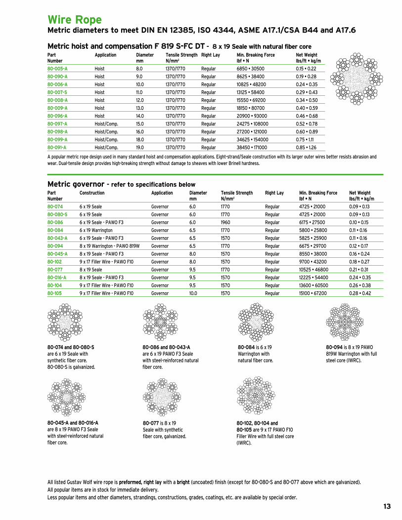
Wire Rope Metric diameters to meet DIN EN 12385, ISO 4344, ASME A17.1/CSA B44 and A17.6
Metric hoist and compensation F 819 S-FC DT - 8 x 19 Seale with natural fiber corePart Application Diameter Tensile Strength Right Lay Min. Breaking Force Net WeightNumber mm N/mm2 lbf • N lbs/ft • kg/m
80-005-A Hoist 8.0 1370/1770 regular 6850 • 30500 0.15 • 0.2280-090-A Hoist 9.0 1370/1770 regular 8625 • 38400 0.19 • 0.2880-006-A Hoist 10.0 1370/1770 regular 10825 • 48200 0.24 • 0.3580-007-S Hoist 11.0 1370/1770 regular 13125 • 58400 0.29 • 0.4380-008-A Hoist 12.0 1370/1770 regular 15550 • 69200 0.34 • 0.5080-009-A Hoist 13.0 1370/1770 regular 18150 • 80700 0.40 • 0.5980-096-A Hoist 14.0 1370/1770 regular 20900 • 93000 0.46 • 0.6880-097-A Hoist/Comp. 15.0 1370/1770 regular 24275 • 108000 0.52 • 0.7880-098-A Hoist/Comp. 16.0 1370/1770 regular 27200 • 121000 0.60 • 0.8980-099-A Hoist/Comp. 18.0 1370/1770 regular 34625 • 154000 0.75 • 1.1180-091-A Hoist/Comp. 19.0 1370/1770 regular 38450 • 171000 0.85 • 1.26
A popular metric rope design used in many standard hoist and compensation applications. eight-strand/seale construction with its larger outer wires better resists abrasion andwear. dual-tensile design provides high-breaking strength without damage to sheaves with lower Brinell hardness.
Metric governor - refer to specifications belowPart Construction Application Diameter Tensile Strength Right Lay Min. Breaking Force Net WeightNumber mm N/mm2 lbf • N lbs/ft • kg/m
80-074 6 x 19 seale governor 6.0 1770 regular 4725 • 21000 0.09 • 0.13 80-080-S 6 x 19 seale governor 6.0 1770 regular 4725 • 21000 0.09 • 0.13 80-086 6 x 19 seale - PAWO F3 governor 6.0 1960 regular 6175 • 27500 0.10 • 0.15 80-084 6 x 19 Warrington governor 6.5 1770 regular 5800 • 25800 0.11 • 0.1680-043-A 6 x 19 seale - PAWO F3 governor 6.5 1570 regular 5825 • 25900 0.11 • 0.16 80-094 8 x 19 Warrington - PAWO 819W governor 6.5 1770 regular 6675 • 29700 0.12 • 0.17 80-045-A 8 x 19 seale - PAWO F3 governor 8.0 1570 regular 8550 • 38000 0.16 • 0.24 80-102 9 x 17 Filler Wire - PAWO F10 governor 8.0 1570 regular 9700 • 43200 0.18 • 0.2780-077 8 x 19 seale governor 9.5 1770 regular 10525 • 46800 0.21 • 0.3180-016-A 8 x 19 seale - PAWO F3 governor 9.5 1570 regular 12225 • 54400 0.24 • 0.35 80-104 9 x 17 Filler Wire - PAWO F10 governor 9.5 1570 regular 13600 • 60500 0.26 • 0.3880-105 9 x 17 Filler Wire - PAWO F10 governor 10.0 1570 regular 15100 • 67200 0.28 • 0.42
All listed gustav Wolf wire rope is preformed, right lay with a bright (uncoated) finish (except for 80-080-s and 80-077 above which are galvanized).All popular items are in stock for immediate delivery.less popular items and other diameters, strandings, constructions, grades, coatings, etc. are available by special order.
80-074 and 80-080-S are 6 x 19 seale with synthetic fiber core.80-080-s is galvanized.
80-086 and 80-043-A are 6 x 19 PAWO F3 seale with steel-reinforced natural fiber core.
80-084 is 6 x 19 Warrington with natural fiber core.
80-094 is 8 x 19 PAWO 819W Warrington with full steel core (IWrC).
80-045-A and 80-016-Aare 8 x 19 PAWO F3 seale with steel-reinforced natural fiber core.
80-077 is 8 x 19seale with synthetic fiber core, galvanized.
80-102, 80-104 and 80-105 are 9 x 17 PAWO F10 Filler Wire with full steel core (IWrC).

Wire Rope Metric diameters to meet DIN EN 12385, ISO 4344, ASME A17.1/CSA B44 and A17.6
Metric hoist and compensation PAWO F3 - 8 x 19 Seale with steel-reinforced natural fiber corePart Application Diameter Tensile Strength Right Lay Min. Breaking Force Net WeightNumber mm N/mm2 lbf • N lbs/ft • kg/m
80-045-A Hoist 8.0 1570 regular 8550 • 38000 0.16 • 0.2480-015-A Hoist 9.0 1570 regular 10850 • 48300 0.21 • 0.3180-017-A Hoist 10.0 1570 regular 13600 • 60500 0.26 • 0.3980-018-A Hoist 11.0 1570 regular 16500 • 73400 0.32 • 0.4780-019-A Hoist 12.0 1570 regular 19525 • 86800 0.37 • 0.5580-021-A Hoist 13.0 1570 regular 23175 • 103100 0.44 • 0.6580-022-A Hoist 14.0 1570 regular 26825 • 119300 0.51 • 0.7580-023-A Hoist/Comp. 15.0 1570 regular 30925 • 137600 0.59 • 0.8780-024-A Hoist/Comp. 16.0 1570 regular 34800 • 154800 0.66 • 0.9880-026-A Hoist/Comp. 18.0 1570 regular 43525 • 193600 0.83 • 1.2380-048-A Hoist/Comp. 19.0 1570 regular 48925 • 217600 0.93 • 1.38
steel-reinforced natural fiber core provides reduced stretch and cross-section deformation with higher breaking strength. eight-strand/seale construction with its larger outer wires increases wear resistance. PAWO F3 comes with a green surface line.
Metric hoist PAWO F7 - 8 x 19 Warrington with steel-reinforced natural fiber corePart Application Diameter Tensile Strength Right Lay Min. Breaking Force Net WeightNumber mm N/mm2 lbf • N lbs/ft • kg/m
80-056-A Hoist 8.0 1570 regular 9125 • 40600 0.18 • 0.2680-027-A Hoist 9.0 1570 regular 11650 • 51800 0.22 • 0.3380-029-A Hoist 10.0 1570 regular 14250 • 63400 0.27 • 0.4080-030-A Hoist 11.0 1570 regular 17275 • 76800 0.33 • 0.4980-031-A Hoist 12.0 1570 regular 20400 • 90700 0.38 • 0.5780-033-A Hoist 13.0 1570 regular 23600 • 105000 0.45 • 0.6780-034-A Hoist 14.0 1570 regular 27950 • 124300 0.53 • 0.7880-035-A Hoist 15.0 1570 regular 31450 • 139900 0.60 • 0.8980-036-A Hoist 16.0 1570 regular 36050 • 160400 0.69 • 1.0280-059-A Hoist 19.0 1570 regular 50725 • 225600 0.96 • 1.42
steel-reinforced natural fiber core provides reduced stretch and cross-section deformation with higher breaking strength. more flexible eight-strand/Warrington construction resists rope fatigue due to bending in installations with numerous rope bends. PAWO F7 comes with a green surface line.
Metric hoist PAWO F7S - 8 x 19 Warrington with Independent Wire Rope CorePart Application Diameter Tensile Strength Right Lay Min. Breaking Force Net WeightNumber mm N/mm2 lbf • N lbs/ft • kg/m
80-056SC Hoist 8.0 1570 regular 10025 • 44600 0.19 • 0.2880-027SC Hoist 9.0 1570 regular 12600 • 56000 0.24 • 0.3680-029SC-S Hoist 10.0 1570 regular 15625 • 69500 0.30 • 0.4480-030SC Hoist 11.0 1570 regular 18675 • 83100 0.35 • 0.5280-031SC Hoist 12.0 1570 regular 22225 • 98900 0.42 • 0.6280-033SC Hoist 13.0 1570 regular 26075 • 116000 0.49 • 0.7380-034SC Hoist 14.0 1570 regular 30300 • 134800 0.58 • 0.8680-035SC Hoist 15.0 1570 regular 34350 • 152800 0.65 • 0.9680-036SC Hoist 16.0 1570 regular 39600 • 176100 0.74 • 1 . 1080-004SC Hoist 18.0 1570 regular 49150 • 218600 0.93 • 1.3880-059SC Hoist 19.0 1570 regular 55125 • 245200 1.04 • 1.54
Full steel core (IWrC) reduces stretch and cross-section deformation to a minimum while maximizing breaking strength. more flexible eight-strand/Warrington construction resists rope fatigue due to bending in installations with numerous rope bends and smaller sheaves. PAWO F7s comes with a green surface line.
All listed gustav Wolf wire rope is preformed, right lay with a bright (uncoated) finish. All popular items are in stock for immediate delivery.less popular items and other diameters, strandings, constructions, grades, coatings, etc. are available by special order.
14

15
Wire Rope Metric diameters to meet DIN EN 12385, ISO 4344, ASME A17.1/CSA B44 and A17.6
Metric hoist PAWO F10 - 9 x 17 Filler Wire with Independent Wire Rope CorePart Application Diameter Tensile Strength Right Lay Min. Breaking Force Net WeightNumber mm N/mm2 lbf • N lbs/ft • kg/m
80-102 Hoist 8.0 1570 regular 9700 • 43200 0.18 • 0.2780-103 Hoist 9.0 1570 regular 12325 • 54800 0.23 • 0.3480-105 Hoist 10.0 1570 regular 15100 • 67200 0.28 • 0.4280-106 Hoist 11.0 1570 regular 18025 • 80200 0.34 • 0.5180-107 Hoist 12.0 1570 regular 21500 • 95600 0.40 • 0.60
designed specifically for demanding high-rise/high-speed applications using rope diameters of 8.0 to 12.0 mm. Full steel core (IWrC) and nine-strand/Filler Wire construction work together to achieve minimal stretch, a round cross-section, excellent flexibility, increased resistance to rope fatigue due to bending and maximized breaking strength. PAWO F10 comes with a white surface line.
Metric hoist and compensation PAWO F10 - 9 x 21 Filler Wire with Independent Wire Rope CorePart Application Diameter Tensile Strength Right Lay Min. Breaking Force Net WeightNumber mm N/mm2 lbf • N lbs/ft • kg/m
80-109 Hoist 13.0 1570 regular 25500 • 113400 0.48 • 0.7180-110 Hoist 14.0 1570 regular 30500 • 135700 0.57 • 0.8580-112 Hoist/Comp. 15.0 1570 regular 34350 • 152800 0.64 • 0.9580-113 Hoist/Comp. 16.0 1570 regular 39125 • 174000 0.73 • 1.0880-116 Hoist/Comp. 18.0 1570 regular 49400 • 219700 0.92 • 1.3780-117 Hoist/Comp. 19.0 1570 regular 55050 • 244900 1.02 • 1.51
designed specifically for demanding high-rise/high-speed applications using rope diameters of 13.0 mm and larger. Full steel core (IWrC) and nine-strand/Filler Wire construction work together to achieve minimal stretch, a round cross-section, excellent flexibility, increased resistance to rope fatigue due to bending and maximized breaking strength. PAWO F10 comes with a white surface line.
Wire Rope with Electrical Conductors Metric diameters to meet DIN EN 12385, DIN EN 1808, ASME A17.1/CSA B44 and A17.6
Metric hoist PAWO F4e - 8 x 19 Seale with synthetic fiber core and two 0.96 mm2 (>18 AWG) conductors Part Application Diameter Tensile Strength Right Lay Min. Breaking Force Net WeightNumber mm N/mm2 lbf • N lbs/ft • kg/m
80-081 Hoist 8.0 1770 regular 7475 • 33200 0.17 • 0.25
galvanized coating on wires and two (2) electrical conductors make this eight-strand/seale rope suitable for use on outdoor maintenance platforms and similar applications. diameters in addition to 8.0 mm are available.
Metric hoist PAWO F5e - 6 x 19 Seale with synthetic fiber core and one 0.96 mm2 (>18 AWG) conductor Part Application Diameter Tensile Strength Right Lay Min. Breaking Force Net WeightNumber mm N/mm2 lbf • N lbs/ft • kg/m
80-067 Hoist 8.0 1770 regular 8600 • 38200 0.16 • 0.23
galvanized coating on wires and one (1) electrical conductor make this six-strand/seale rope suitable for use on outdoor maintenance platforms and similar applications. diameters in addition to 8.0 mm are available.
All listed gustav Wolf wire rope is preformed, right lay with a bright (uncoated) finish (except for 80-081 and 80-067 above which are galvanized). All popular items are in stock for immediate delivery.less popular items and other diameters, strandings, constructions, grades, coatings, etc. are available by special order.

16
Wire Rope AccessoriesTo meet ASME A17.1/CSA B44 • New York MEA approval #410-03-M
Wire rope wedge sockets Part Rope Size Dim (A) nom Dim (B) nom Dim (C) Usable Thread Dim (D) nom Number inches • mm inches • mm inches • mm Metric minimum inches • mm (+/- 3/16 • 5) (+/- 3/16 • 5) Thread inches • mm (+/- 3/8 • 10)
WSY-516-12 5/16 • 8 17-1/2 • 445 12-19/32 • 320 m12 7-7/8 • 200 8-27/32 • 225 WSY-516-18 5/16 • 8 23-3/4 • 603 18-7/8 • 480 m12 9-13/16 • 250 10-13/16 • 275 WSY-516-24 5/16 • 8 30-1/8 • 765 24-3/16 • 640 m12 15-3/4 • 400 16-23/32 • 425 WSY-38-12 3/8 • 9 to 10 17-1/2 • 445 12-19/32 • 320 m12 7-7/8 • 200 8-27/32 • 225 WSY-38-18 3/8 • 9 to 10 23-3/4 • 603 18-7/8 • 480 m12 9-13/16 • 250 10-13/16 • 275 WSY-38-24 3/8 • 9 to 10 30-1/8 • 765 24-3/16 • 640 m12 15-3/4 • 400 16-23/32 • 425 WSY-12-12-A 7/16 to 1/2 • 11 to 13 18 • 457 12-19/32 • 320 m20 7-7/8 • 200 8-27/32 • 225 WSY-12-18-A 7/16 to 1/2 • 11 to 13 24-3/8 • 619 18-7/8 • 480 m20 9-13/16 • 250 10-13/16 • 275 WSY-12-24-A 7/16 to 1/2 • 11 to 13 30-5/8 • 778 24-3/16 • 640 m20 15-3/4 • 400 16-23/32 • 425 WSY-12-30-A 7/16 to 1/2 • 11 to 13 36-7/8 • 937 30-1/2 • 800 m20 15-3/4 • 400 16-23/32 • 425 WSY-12-36-A 7/16 to 1/2 • 11 to 13 43-1/4 • 1099 36-13/16 • 960 m20 15-3/4 • 400 16-23/32 • 425 WSY-58-12 9/16 to 5/8 • 14 to 16 19-3/4 • 502 12-19/32 • 320 m20 7-7/8 • 200 8-27/32 • 225 WSY-58-18 9/16 to 5/8 • 14 to 16 26-1/8 • 664 18-7/8 • 480 m20 9-13/16 • 250 10-13/16 • 275 WSY-58-24 9/16 to 5/8 • 14 to 16 32-3/8 • 822 24-3/16 • 640 m20 15-3/4 • 400 16-23/32 • 425 WSY-58-30 9/16 to 5/8 • 14 to 16 38-3/4 • 984 30-1/2 • 800 m20 15-3/4 • 400 16-23/32 • 425 WSY-58-36 9/16 to 5/8 • 14 to 16 45 • 1143 36-13/16 • 960 m20 15-3/4 • 400 16-23/32 • 425 WSY-34-12 11/16 to 3/4 • 17.5 to 19 21-1/4 • 540 12-19/32 • 320 m24 7-7/8 • 200 8-27/32 • 225 WSY-34-18 11/16 to 3/4 • 17.5 to 19 27-1/2 • 699 18-7/8 • 480 m24 9-13/16 • 250 10-13/16 • 275 WSY-34-24 11/16 to 3/4 • 17.5 to 19 33-3/4 • 857 24-3/16 • 640 m24 15-3/4 • 400 16-23/32 • 425 WSY-34-30 11/16 to 3/4 • 17.5 to 19 39-3/4 • 1010 30-1/2 • 800 m24 15-3/4 • 400 16-23/32 • 425 WSY-34-36 11/16 to 3/4 • 17.5 to 19 46-1/4 • 1175 36-13/16 • 960 m24 15-3/4 • 400 16-23/32 • 425
each wedge socket consists of the socket, rod, 1 wedge, 2 nuts, 1 washer, 1 cotter pin and 2 retaining clips.
Wedge sockets are tested with full steel core (IWrC) rope and exceed Asme A17.1 rule 2.20.9 and all other applicable safety codes.
Component Specifications: socket: Cast steel AsTm-A27, grade 60-30 stress relieved rod: rolled or forged steel AsTm 668 Wedge: Cast steel AsTm-A27, grade 60-30
Wedge socket wedges Part Size / Color Number inches • mm / color
WS-WEDGE-516 5/16 • 8 / green WS-WEDGE-38 3/8 • 9 to 10 / blue
WS-WEDGE-12-B 7/16 to 1/2 • 11 to 13 / black WS-WEDGE-58 9/16 to 5/8 • 14 to 16 / red WS-WEDGE-34 11/16 to 3/4 • 17.5 to 19 / yellow
Wedge: Cast steel AsTm-A27, grade 60-30 These wedges are for use Only with the wedge sockets listed above.
Wedge socket retaining clips Part Size and Description Number inches • mm
WS-CLIP-38 5/16 to 3/8 • 8 to 10 retaining clip WS-CLIP-1258 7/16 to 5/8 • 11 to 16 retaining clip WS-CLIP-34 11/16 to 3/4 • 17.5 to 19 retaining clip
Governor rope wedge sockets Part Size and Description Number inches • mm
WSY-38-GOV 3/8 • 10 wedge socket, wedge and 2 retaining clips, 14 mm mounting hole WSY-12-GOV 1/2 • 13 wedge socket, wedge and 2 retaining clips, 17.5 mm mounting hole
Wedge socket components Part Size and Description Number inches • mm
WS-NUT-38 5/16 to 3/8 • 8 to 10 nut WS-NUT-12 7/16 to 1/2 • 11 to 13 nut WS-NUT-58 9/16 to 5/8 • 14 to 16 nut WS-NUT-34 11/16 to 3/4 • 17.5 to 19 nut WS-CPIN-38 5/16 to 3/8 • 8 to 10 cotter pin WS-CPIN-12 7/16 to 1/2 • 11 to 13 cotter pin WS-CPIN-58 9/16 to 5/8 • 14 to 16 cotter pin WS-CPIN-34 11/16 to 3/4 • 17.5 to 19 cotter pin WS-WSHR-38 5/16 to 3/8 • 8 to 10 washer WS-WSHR-12 7/16 to 1/2 • 11 to 13 washer WS-WSHR-58 9/16 to 5/8 • 14 to 16 washer WS-WSHR-34 11/16 to 3/4 • 17.5 to 19 washer
A
B
D
C

17
Wire Rope AccessoriesTo meet ASME A17.1/CSA B44
Rope isolation bushing springs - assemblies and components Part Size and Description Spring Length† nom Spring O.D. nom Spring I.D. nom Number inches • mm inches • mm inches • mm inches • mm
WS-SA-38* 5/16 to 3/8 • 8 to 10 complete assembly 4-13/16 • 122 1-5/16 • 33 11/16 • 17 WS-SA-12-A* 7/16 to 1/2 • 11 to 13 complete assembly 6-1/8 • 156 1-15/16 • 49 1 • 25 WS-SA-58* 9/16 to 5/8 • 14 to 16 complete assembly 6-7/8 • 175 2-1/2 • 64 1-1/4 • 32 WS-SA-34* 11/16 to 3/4 • 17.5 to 19 complete assembly 7-1/16 • 179 3-11/32 • 85 2-9/16 • 65 WS-IBUSH-38 5/16 to 3/8 • 8 to 10 bushing - - - WS-IBUSH-12-A 7/16 to 1/2 • 11 to 13 bushing - - - WS-IBUSH-58 9/16 to 5/8 • 14 to 16 bushing - - - WS-IBUSH-34 11/16 to 3/4 • 17.5 to 19 bushing - - - WS-SPR-38 5/16 to 3/8 • 8 to 10 bushing spring 4-13/16 • 122 1-5/16 • 33 11/16 • 17 WS-SPR-12 7/16 to 1/2 • 11 to 13 bushing spring 6-1/8 • 156 1-15/16 • 49 1 • 25 WS-SPR-58 9/16 to 5/8 • 14 to 16 bushing spring 6-7/8 • 175 2-1/2 • 64 1-1/4 • 32 WS-SPR-34 11/16 to 3/4 • 17.5 to 19 bushing spring 7-1/16 • 179 3-11/32 • 85 2-9/16 • 65 WS-BUSH-38 5/16 to 3/8 • 8 to 10 bushing washer - - - WS-BUSH-12-A 7/16 to 1/2 • 11 to 13 bushing washer - - - WS-BUSH-58 9/16 to 5/8 • 14 to 16 bushing washer - - - WS-BUSH-34 11/16 to 3/4 • 17.5 to 19 bushing washer - - -
*each isolation bushing spring assembly includes 1 spring, 3 bushings and 2 washers. The wedge socket is nOT included. †spring measured when relaxed.
Component Specifications: socket: Cast steel AsTm-A27, grade 60-30 stress relieved rod: rolled or forged steel AsTm 668 Wedge: Cast steel AsTm-A27, grade 60-30
Babbitt sockets Part Rope Size Dim (A) nom Dim (B) nom Metric Number inches • mm inches • mm inches • mm Thread
BSY-12-12 1/2 • 13 18 • 457 12 • 305 m20 BSY-12-18 1/2 • 13 24 • 610 18 • 457 m20 BSY-12-24 1/2 • 13 30 • 762 24 • 610 m20 BSY-58-12 5/8 • 16 19 • 483 12 • 305 m24 BSY-58-18 5/8 • 16 25 • 635 18 • 457 m24 BSY-58-24 5/8 • 16 31 • 787 24 • 610 m24
All Babbitt sockets are special order and are not normally stocked.
Component Specifications: socket: Forged carbon steel per JIs s35C or s38C equivalent to sAe 1035 or 1038, hot forged then normalized and tempered Hex nuts: AsTm A563 grade O Cotter pin: steel, per AnsI B5.20
A
B

18
DrakaLube™ wire rope treatment/lubricant Part Description Number
WR-DRAKALUBE DrakaLube wire rope treatment/lubricant, 1 gallon • 3.785 liter jug
drakalube wire rope treatment/lubricant has been specifically formulated for use with all types and brands of elevator wire rope. drakalube penetrates the rope core and contains additives that fight bending stresses, high groove pressures, friction, wear and corrosion. most importantly, it can also displace moisture in the rope core.
Gustav Wolf T 86™ wire rope lubricant Part Description Number
80-4500T8601 Gustav Wolf wire rope lubricant, 0.264 gallon • 1 liter bottle
T 86 lubricant is a low-viscosity fluid which absorbs readily into the rope interior. It contains solvent (the flash point is 140° F • 60° C before the evaporation of the solvent and 455° F • 235° C after the evaporation of the solvent). Approximately 50% of the lubricant remains in the rope after evaporation of the solvent. For T 86 safe handling instructions, refer to the associated msds information available at www.gustav-wolf.com. T 86 is supplied in a handy one liter applicator bottle.
Rope oilers Part Description Number
MIS-100 Automatic rope oiler, with 9 in • 229 mm wick MIS-102 Automatic rope oiler, with 12 in • 305 mm wick MIS-103 Extension bracket, for rope oiler MIS-103A Replacement wick, for all size rope oilers MIS-103B Replacement wick, 1/2 x 6 1/2 x 12 in • 12.7 x 165 x 305 mm
The automatic rope oiler is nOT recommended for use with T 86 rope lubricant.
Reeving splices - for right lay ropes only Part Color Code For Rope Diameter Length Rod Diameter Max. Working Load Number inches • mm inches • mm inches • mm lbs • kg
RS-2103 yellow 3/8 • 9.5 22 • 559 .051 • 1.3 300 • 136 RS-2105 Orange 1/2 • 12.7 29 • 736 .070 • 1.8 2000 • 907 RS-2107 Black 5/8 • 15.9 36 • 914 .086 • 2.2 2000 • 907
reeving splices are provided three to a package. Use OnCe and then discard. Other sizes are available.
Cable bands Part For Rope Diameter Quantity in Number inches • mm Package
WR-CB-38 3/8 • 9.5 50 WR-CB-12 1/2 • 12.7 50 WR-CB-58 5/8 • 15.9 50
Selector/hoistway door relating cable - preformed, flexible and zinc-coated Part Diameter Stranding Min. Breaking Force Net Weight Number inches • mm lbf • kgf lbs/kft • kg/km
040219 1/16 • 1.6 7 x 7 480 • 218 7.5 • 11 040218 3/32 • 2.4 7 x 7 920 • 418 16 • 24 040215 1/8 • 3.2 7 x 19 2000 • 907 29 • 43 040216 5/32 • 4.0 7 x 19 2800 • 1270 45 • 67 040220 3/16 • 4.8 7 x 19 4200 • 1905 65 • 97 040225 1/4 • 6.4 7 x 19 7000 • 3175 110 • 164
do nOT use selector/hoistway door relating cable for hoisting applications.
Wire Rope Accessories
Wire rope clips - malleable iron Part For Rope Diameter Number inches • mm
79-107 1/8 • 3.2 79-114 3/16 • 4.8 79-122 1/4 • 6.4 79-123 3/8 • 9.5 79-126 1/2 • 12.7 79-127 5/8 • 15.9

19
RTS Rope Tensioning System portable, mounts on individual ropes above car or counterweight Part Description Number
WR-RTS Control unit for RTS rope tensioning system, includes lCd touch-screen operation with built-in power supply, UsB cable for PC connection, T-handle allen wrench (for attaching sensors to ropes), six (6) sensors and hard-shell carrying case WR-WRS Wire rope sensor for RTS system, additional sensor and couplings for rope diameters of 1/6 in • 4 mm to 5/8 in • 16 mm, order one per rope from 7 up to a maximum of 12 per control unit (six sensors are included with part number Wr-rTs)
The rTs (rope Tensioning system) is a portable electronic device for quickly and accurately measuring the tension of elevator wire ropes within an accuracy of 3%. The system includes a lCd touch-screen control unit with a capacity of up to 12 sensors attached via UsB connections (six sensors are included with part number Wr-rTs).
In the Weighing mode, the individual rope tension readings and average weight are shown graphically and numerically in either imperial or metric units for up to 12 ropes. The clearly displayed tension information allows the field technician to quickly and accurately equalize the rope tensions. since the information is displayed in real time for each rope, the impact of a tensioning adjustment made to one rope is immediately visible on the other ropes.
In the Adjust mode, the before and after tension values for up to 150 installations can be stored in the internal memory. This information can then be downloaded to a PC via the included UsB cable.
Coupling hardware for each sensor is included which permits the sensors to be attached to rope diameters of 1/6 in • 4 mm to 5/8 in • 16 mm. each sensor has a maximum capacity of 2400 lbs • 1200 kg.
The weight of the cab and counterweight can also be conveniently and precisely measured with the rTs.
Features
Portable readout in both pounds and kilograms Accurate to within 3% Can measure up to 12 ropes at once with a maximum weight of 2400 lbs • 1200 kg per rope Both graphic and numeric displays Fits 1/6 in • 4 mm to 5/8 in • 16 mm ropes display languages include english, spanish, german, Italian, French and Portuguese Comes with all cables, T-handled allen wrench and a hard-shell case six sensors are included, with a capacity of up to 12 sensors stores and downloads to PC pre- and post-tensioning values low battery indicator Factory reset switch
Heavy duty RTS Rope Tensioning System similar to rTs above but for higher-capacity elevators with larger hoist ropes Part Description Number
WR-RTS-A Control unit for heavy duty RTS rope tensioning system, includes lCd touch-screen operation with built-in power supply, UsB cable for PC connection, T-handle allen wrench (for attaching sensors to ropes), six (6) sensors and hard-shell carrying case WR-WRS-A Wire rope sensor for heavy duty RTS system, additional sensor and couplings for rope diameters of 1/2 in • 13 mm to 3/4 in • 20 mm, order one per rope from 7 up to a maximum of 12 per control unit (six sensors are included with part number Wr-rTs-A)
The heavy duty version of the rTs is for higher-capacity elevators with larger hoist ropes. It has all of the features of the standard rTs but with a sensor that fits 1/2 in • 13 mm to 3/4 in • 20 mm ropes. each sensor has a maximum capacity of 6600 lbs • 3000 kg.
Features
similar to rTs above, except can measure up to 12 ropes at once with a maximum weight of 6600 lbs • 3000 kg per rope Fits 1/2 in • 13 mm to 3/4 in • 20 mm ropes
Wire Rope ToolsTension measuring

20
Wire Rope ToolsTension/diameter measuring and cutting
Quick-Balance tension meter Part Description Number
WR-QBTM-2 Wire rope tension measurement meter, 10000 lbf/4500 kgf/45000 n capacity
The Quick-Balance tension meter can be attached to a rope, used to measure tension, and removed in just seconds. In the Balance mode the load on each rope can be adjusted to equalize tensioning across all ropes. The device also allows a single field technician to determine the weight of the elevator and counterweight in minutes. The digital load cell assures accuracy of up to +/- 3% when calibrated to the specific rope size and type.
The meter is shipped from the factory with 1/2 in • 12.7 mm, 9/16 in • 14.3 mm and 5/8 in • 15.9 mm diameter calibrations (other diameters are available by special order). The standard sheave set accommodates rope diameters of 1/4 in • 6.4 mm through 3/4 in • 19 mm. A hard-shell carrying case is included.
Digital caliper Part Description Number
WR-CALIPER-C Digital wire rope caliper, imperial and metric scales, includes special jaws for ease of use and a hard-shell carrying case
Measuring tool - conforms to Asme A17.6 standard Part Description Number
WR-MT Wire rope measuring gauge, for imperial diameters, go/no go style, 3/8, 7/16, 1/2, 9/16, 5/8, 11/16 and 3/4 in WR-MT-METRIC Wire rope measuring gauge, for metric diameters, go/no go style, 6, 8, 10, 11, 12, 13, 16 and 19 mm
Convenient machined-aluminum tool for quick and accurate measurement of wire rope diameters. If the rope fits in the groove, or if a rope with rouge fits the stepped groove, retire the rope.
Impact-style rope cutter Part Description Number
WR-IMPACT Impact-style wire rope cutter, morse-starrett 101, for diameters up to 3/4 in • 19 mm
Hydraulic-style rope cutter Part Description Number
WR-HYDRAULIC Hydraulic-style wire rope cutter, morse-starrett W-075, for diameters up to 3/4 in • 19 mm
Ratchet-style rope cutter Part Description Number
WR-RATCHET Ratchet-style wire rope cutter, Cooper Tools 8690 Tn, for diameters up to 3/4 in • 19 mm

General Information
Note on New Ropes and Existing Sheaves 1
Codes and Standards 1
Replacement Criteria (ASME A17.1/CSA B44 and A17.6) 1 - 4
Ordering 5
Handling, Tensioning and Surface Line 6
Wire Rope Installation 7
Wedge Socket Installation 8
Re-lubrication 9
Wire Rope
Selection Guide for Imperial Diameters 10
Imperial Diameters for Standard Applications 11
Imperial Diameters for Special Applications 12
Metric Diameters 13 - 15
Metric Diameters with Electrical Conductors 15
Wire Rope Accessories
Wedge Sockets and Wedge Socket Components 16 - 17
Babbitt Sockets 17
Lubricants and Oilers 18
Reeving Splices, Cable Bands and Rope Clips 18
Selector/Door Cable 18
Wire Rope Tools
Tension Measuring 19 - 20
Diameter Measuring 20
Cutting 20
In 2012 Gustav Wolf, headquartered in Germany, celebrated its 125th anniversary and is widely recognized as one of the world’s most important producers of steel wire ropes for elevators. Today, with six factories in five countries, we offer a full line of elevator wire ropes designed and manufactured to meet the requirements of the elevator industry worldwide.
Our product line for elevator ropes includes imperial and metric diameters in natural and synthetic fiber core, PAWO F3 und PAWO F7 steel-reinforced natural fiber core, PAWO F7S and PAWO 819W full steel core, PAWO F10 nine-strand full steel core, TopTrac™ nine-strand full steel core in double-parallel lay, CompactTrac™ compacted-strand natural fiber core, PowerTrac™ compacted- strand full steel core and PAWO F4e and PAWO F5e synthetic fiber core galvanized ropes with electrical conductor(s) for use on outdoor maintenance platforms and similar applications.
©2016 Gustav Wolf (USA), Inc.Information in this catalog is subject to change at any time without notice.
Table of Contents
Gustav Wolf wire ropes are available from:Draka (US/Canada) 1-877-DRAKA-EP (1-877-372-5237) Benfield (Metro NYC) 1-718-706-8600 S.E.E.S. Inc. (Florida) 1-800-526-0026For technical support 1-919-878-5605
www.gustav-wolf.com
10
20
high, mid, low,
fast or slow,
gustav wolf
has the rope
you need.
pawo f10
for high-rise
and high-speeds
PAWO F10 is designed for high-rise/
high-speed elevators. Its full steel core
nine-strand/filler wire design achieves
the ultimate in performance.
pawo f3
for mid-rise
and mid-speeds
PAWO F3 is for mid-rise/mid-speed
elevators, with a steel-reinforced core
that reduces/eliminates the labor cost
of repeated rope shortening.
low-stretch
Natural Fiber Core
for low-rises
Low-Stretch, the economical low-rise
choice, delivers prestretched perfor-
mance without the premium price.
Compacttrac™
for basement machines
CompactTrac™, designed for use with
basement machines, uses compacted
strands to extend reverse-bend rope
service life.
Gustav Wolf factory circa 1887

North American distribution locations and ordering information
United States
Draka Elevator Products 877-DRAKA-EP (877-372-5237) (252-972-6001 7• Chicago (Schaumburg, IL)• Houston, TX• Los Angeles (Commerce, CA)• Memphis (Walnut, MS)• Metro NYC (Long Island City, NY)• Rocky Mount, NC
Benfield Electric & Elevator Supply Corp.718-706-8600 (718-706-8665 7• Metro NYC (Bronx, NY) S.E.E.S., Inc./Southern Elevator & Electric Supply 800-526-0026 (954-917-7337 7• Pompano Beach, FL Canada
Draka Elevator Products 877-DRAKA-EP (877-372-5237) (252-972-6001 7• Calgary, AB• Edmonton, AB• Toronto (Brantford, ON)• Vancouver, BC
Mexico
Draka Elevator Products 252-972-6000 (252-972-6001 7
North American technical supportGustav WolfRichard L. LindemeyerGeneral Manager – North America 919-878-5605 ([email protected]
Elevator Ropes and Accessoriesfor North America5th Edition