north american 2014 microtunnelingtrenchlesstechnology.com/pdfs/2014-micro-supp.pdf · special...
TRANSCRIPT
ALSO INSIDE
NORTH AMERICAN MICROTUNNELING
I N D U S T R Y R E V I E W
2014
ACHIEVEMENT AWARDColuccio’s Rene Inosanto, MWH’s Greg Raines and Contractor Ward and Burke Earn Honors
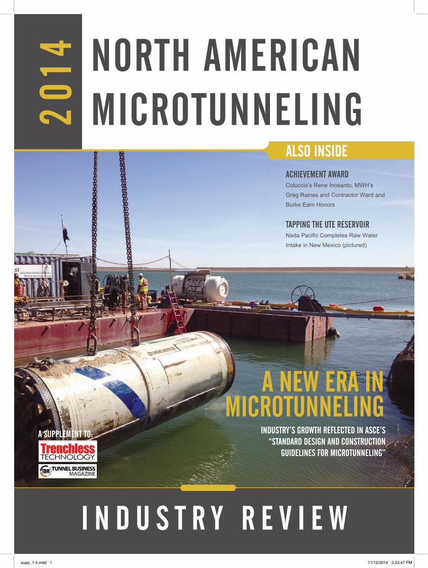
TAppING THE UTE RESERVOIRNada Pacific Completes Raw Water Intake in New Mexico (pictured)
A NEW ERA IN MICROTUNNELING
A SUppLEMENT TO: INDUSTRY’S GROWTH REfLECTED IN ASCE’S “STANDARD DESIGN AND CONSTRUCTION
GUIDELINES fOR MICROTUNNELING”
supp_1-5.indd 1 11/12/2014 3:23:47 PM
supp_1-5.indd 2 11/12/2014 3:23:50 PM
3
tunnelingonline.com SpECIAL SUppLEMENT: NORTH AMERICAN MICROTUNNELING
AECOM .......................................................................................................... 13Akkerman Inc.................................................................................................. 17Barbco ............................................................................................................ 11Benjamin Media Resource Center ................................................................. 23Bradshaw Construction Corporation .............................................................. 13Colorado School of Mines Microtunneling Short Course .................................. 5Derrick Equipment Co. .....................................................................Back Cover
Herrenknecht Tunneling Systems .................................................................... 2Hobas Pipe USA Inc. ........................................................................................ 9Jacobs Associates ............................................................................................ 7Microtunneling Inc. ......................................................................................... 25Northeast Remsco .......................................................................................... 19Rhino Traders ................................................................................................. 27Ward & Burke Microtunneling ......................................................................... 15
TABLE Of CONTENTSEDITOR’S MESSAGE ASCE’s update of its microtunneling guidelines highlights industry developments in 2014.By: Jim Rush
DEVELOpING THE NEW STANDARDA look inside the publication of ASCE’s Standard Design and Construction Guidelines for Microtunneling. By: Jim Rush
MICROTUNNELING ACHIEVEMENT AWARD WINNERS Coluccio’s Rene Inosanto, MWH’s Greg Raines and contractor Ward and Burke will be honored during the 2015 Microtunneling Short Course at the Colorado School of Mines in February.
DESIGN-BUILD IN CINCINNATINew contracting method helps save money and time on utility construction project.
TAppING THE UTE RESERVOIRNada Pacific constructs a raw water intake in Logan, New Mexico, using microtunneling. By: Laura Anderson
4
20
6
13
18
OVERCOMING THE CHALLENGES Of MIxED fACE MICROTUNNELINGBradshaw Construction completes difficult crossing of the Schuylkill River in Reading, Pennsylvania. By: Jim Rush
DIRECTORYA listing of microtunneling contractors and suppliers in the United States and Canada.
JOB LOGA recap of recently completed, ongoing and upcoming microtunneling projects in North America.
TRENCHLESS DEfINITIONSA glossary of terms used in the microtunneling industry. This is excerpted from the ASCE’s forthcoming Standard Design and Construction Guidelines for Microtunneling.
28
32
24
26
ADVERTISERS INDEx
supp_1-5.indd 3 11/12/2014 3:23:52 PM

Jim Rush | Editor
4
pUBLISHERBernard P. [email protected]
EDITORIALEditor: James W. [email protected]
Managing Editor: Sharon M. [email protected]
Assistant Editor: Mike [email protected]
Contributing Staff Editors:Andrew Farr • Brad Kramer • Keith Gribbins Kelly Pickerel • Pam Kleineke
SALES+MARKETINGMarketing Director: Kelly [email protected]
Brand Sales Manager: Dan [email protected]
Regional Sales Representative: Renee [email protected]
Conferences Sales Coordinator: Brittany [email protected]
pRODUCTION+fULLfILLMENTProduction Manager: Chris [email protected]
Graphic Artists:Sarah Haughawout • Joan SatowDeborah McManus • Elizabeth Stull
Web/Interactive Manager: Mark [email protected]
Fulfillment Specialist: Lillian [email protected]
Chief Executive Officer: Bernard P. [email protected]
President: Robert Krzys [email protected]
Controller: Marianne [email protected]
10050 Brecksville Rd.Brecksville, OH 44141 USA (330) 467-7588 • Fax: (330) 468-2289 www.trenchlessonline.com e-mail: [email protected]
EDITOR’S MESSAGE
EVOLUTION Of THE INDUSTRY
When we first published the Microtun-neling Annual in 2009, the biggest news were some of the exciting projects that were expanding the boundaries of the industry in North America. Longer drives, curved drives and the completion of proj-ects through difficult ground conditions were among the highlights of those first few issues.
While we continue to innovate and im-prove, the biggest development this year has been the compilation of the ASCE’s “Standard Design and Construction Guidelines for Microtunneling,” which are on track to be published in early 2015. The document is a revision of a 2001 publica-tion and incorporates the substantial de-velopments in the industry over the inter-vening time.
Glenn Boyce of Jacobs Associates is the chairman of the committee respon-sible for publishing the revised guidelines. “The intent of the update is to incorporate new changes; the technology is changing and there are new procedures and adopt-ed practices,” he said.
One recent significant development in the industry was the founding of the North American Microtunneling Associa-tion (NAMA) in 2012. NAMA represents major microtunneling contractors active in the United States and Canada. NAMA was invited to participate in the process of revising the guidelines and helped to broaden its scope through its construction experience.
The result, according to committee member Dave Bennett of Bennett Trench-less Engineers, is a useful tool for all par-ties involved in microtunneling. “I believe
we have achieved a very practical docu-ment that has a tremendous amount of de-tail, yet it avoids being overly prescriptive,” he said. “It allows innovation. It allows judgment. It allows experienced practitio-ners the flexibility to use that experience and judgment.”
We explore this issue further beginning on page 6. We invited members of the committee to discuss the process behind creating the document, its goals and the industry in general.
On page 18 we present the Oakley Sta-tion sewer separation project in Cincinnati. While it is not technically a microtunneling project, this trenchless pipe jacking and utility tunneling project is interesting in the fact that it showcases the use of trench-less new construction in conjunction with design-build contracting. By using design-build as part of this redevelopment proj-ect, the owner – the Metropolitan Sewer District of Greater Cincinnati (MSD) – was able to save 13 months off the schedule and more than 20% from the initial con-struction estimate of $12.2 million – all the while helping MSD to agree to terms of its EPA consent decree to control sanitary and combined sewer overflows. What is also interesting about this project is the fact that it is one of the first to be complet-ed in the State of Ohio to use design-build contracting, which until recently had not been permissible under Ohio’s construc-tion laws.
As microtunneling marked its 30th an-niversary in North America in 2014, there is still room for the market to grow.
Regards,
SpECIAL SUppLEMENT: NORTH AMERICAN MICROTUNNELING trenchlessonline.com
supp_1-5.indd 4 11/12/2014 3:23:54 PM
Course DirectorsTimothy CossLevent Ozdemir
Organized by:Microtunneling, Inc. Ozdemir Engineering Trenchless Technology
In Cooperation With:Office of Special Programs and Continuing Education Colorado School of Mines
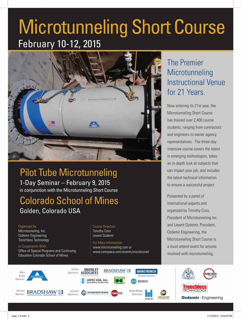
Microtunneling Short CourseFebruary 10-12, 2015
Pilot Tube Microtunneling1-Day Seminar – February 9, 2015in conjunction with the Microtunneling Short Course
Colorado School of MinesGolden, Colorado USA
For More Information:www.microtunneling.com or www.csmspace.com/events/microtunnel
Main Event
Sponsor:
Coffee Sponsors:
Session Sponsor:
Lanyard Sponsors:
Name Badge Sponsors:
TM
The Premier Microtunneling Instructional Venue for 21 Years.Now entering its 21st year, the
Microtunneling Short Course
has trained over 2,400 course
students, ranging from contractors
and engineers to owner agency
representatives. The three-day
intensive course covers the latest
in emerging technologies, takes
an in-depth look at subjects that
can impact your job, and includes
the latest technical information
to ensure a successful project.
Presented by a panel of
international experts and
organized by Timothy Coss,
President of Microtunneling Inc.
and Levent Ozdemir, President,
Ozdemir Engineering, the
Microtunneling Short Course is
a must-attend event for anyone
involved with microtunneling.
supp_1-5.indd 5 11/12/2014 3:23:55 PM
SPECIAL SUPPLEMENT: NORTH AMERICAN MICROTUNNELING trenchlessonline.com
6
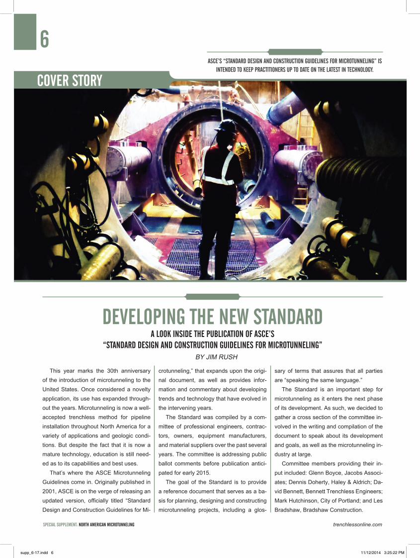
COVER STORY
ASCE’S “STANdARd dESIGN ANd CONSTRUCTION GUIdELINES fOR MICROTUNNELING” IS INTENdEd TO kEEP PRACTITIONERS UP TO dATE ON THE LATEST IN TECHNOLOGY.
This year marks the 30th anniversary of the introduction of microtunneling to the United States. Once considered a novelty application, its use has expanded through-out the years. Microtunneling is now a well-accepted trenchless method for pipeline installation throughout North America for a variety of applications and geologic condi-tions. But despite the fact that it is now a mature technology, education is still need-ed as to its capabilities and best uses.
That’s where the ASCE Microtunneling Guidelines come in. Originally published in 2001, ASCE is on the verge of releasing an updated version, officially titled “Standard Design and Construction Guidelines for Mi-
crotunneling,” that expands upon the origi-nal document, as well as provides infor-mation and commentary about developing trends and technology that have evolved in the intervening years.
The Standard was compiled by a com-mittee of professional engineers, contrac-tors, owners, equipment manufacturers, and material suppliers over the past several years. The committee is addressing public ballot comments before publication antici-pated for early 2015.
The goal of the Standard is to provide a reference document that serves as a ba-sis for planning, designing and constructing microtunneling projects, including a glos-
sary of terms that assures that all parties are “speaking the same language.”
The Standard is an important step for microtunneling as it enters the next phase of its development. As such, we decided to gather a cross section of the committee in-volved in the writing and compilation of the document to speak about its development and goals, as well as the microtunneling in-dustry at large.
Committee members providing their in-put included: Glenn Boyce, Jacobs Associ-ates; Dennis Doherty, Haley & Aldrich; Da-vid Bennett, Bennett Trenchless Engineers; Mark Hutchinson, City of Portland; and Les Bradshaw, Bradshaw Construction.
dEVELOPING THE NEw STANdARd
By JIM RUSH
A LOOk INSIdE THE PUbLICATION Of ASCE’S “STANdARd dESIGN ANd CONSTRUCTION GUIdELINES fOR MICROTUNNELING”
supp_6-17.indd 6 11/12/2014 3:25:22 PM
7
tunnelingonline.com SPECIAL SUPPLEMENT: NORTH AMERICAN MICROTUNNELING
wHAT wAS THE IMPETUS fOR UPdATING THE STANdARd? wHAT dO YOU HOPE TO ACCOMPLISH wITH THE PUbLICATION Of THE UPdATEd dOCUMENT?
GLENN BOYCE – To be an ASCE Standard, there are certain protocols and requirements that must be met. One of them is that it needs to be updated every five years to keep current. The committee began the process of updating the original Standard in 2008, but didn’t really get going in earnest until 2010.
The intent of the update is to incorporate new changes; the technology is changing and there are new procedures and adopted practices. The process of writing the origi-nal Standard started in 1995 and took six years to complete. It didn’t go into the level of detail that some thought that it should have, but I believe we were successful in getting people’s attention and getting them started on the right path. The idea with the revision is to try to make it much more in-formative, much more adopted to the prac-tices and changes that have occurred in the industry. One thing that has helped has been the involvement of the North Ameri-can Microtunneling Association (NAMA), which is a group of the 15 largest micro-tunneling contractors in North America that formed within the last couple of years. They got involved and added their thoughts and needs and what they felt were areas that needed improvement.
So it has taken awhile, but we are hop-ing to create document that is up-to-date, with current technology, and will be used by everyone in the industry.
MARK HUTCHINSON – I attended training in the 1990s presented by Glenn Boyce using the old ASCE Standard. The old ASCE standard was a good introduc-tion to microtunneling; it discussed the ma-jor subjects which were relatively new at the time.
I hope the new Standard provides a framework of the best practices and raises questions owners should be asking their consultants and themselves when con-sidering microtunneling as an option for a project. I also hope that the document can be used to educate owners’ engineers on the private and government side about the usefulness of the tool and how to have a successful project.
LES BRADHSAW – There have been substantial improvements in microtunnel-ing and the utilization of the method. With our broadened experience and equipment, we are able to complete projects in ground conditions – like rock and soft soils – that we could not do 15 years ago. We tried to address all these improvements in the Standard. I also think we did a better job of summarizing the history, the methodolo-gies, and the lessons learned. As contrac-tors, NAMA was reluctant to get involved
initially, but we couldn’t be happier with the response from the engineering lead-ers of this new Standard in working with us to make things not just theoretical, but practical and usable. I think it really reflects where the industry is. It is a work in prog-ress, however, and there are new challeng-es out there that are being embraced every day. The industry is moving forward in spite of the deepest recession this country has seen since the 1930s.
DAVE BENNETT – NAMA and its con-tractor members brought a lot of practical experience and knowledge to bear. One of the things that I am most proud of, is that I believe we have achieved a very practical document that has a tremendous amount of detail, yet it avoids being overly prescrip-tive. It allows innovation. It allows judg-ment. It allows experienced practitioners the flexibility to use that experience and judgment.
supp_6-17.indd 7 11/12/2014 3:25:23 PM
SPECIAL SUPPLEMENT: NORTH AMERICAN MICROTUNNELING trenchlessonline.com
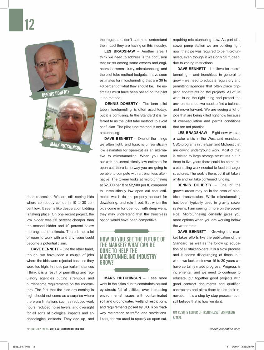
DENNIS DOHERTY – The original document was referred to as “Standard Construction Guidelines for Microtunnel-ing,” and it was realized that engineers who were perhaps not experienced were referring to the document, so with this re-vision we changed it to “Standard Design and Construction Guidelines for Microtun-neling” so that owners and engineers can understand the details that go into making a successful project.
wHAT ARE SOME Of THE SPECIfIC AREAS THAT wERE CHANGEd OR AddEd? wHY?
GLENN BOYCE – When we wrote the original Standard in the 1990s and into the early 2000s, microtunneling was used primarily in soils and generally in smaller diameters. Now the industry has migrat-ed into larger machines with more horse-power and more torque, so we are able to go through rock conditions. We have gone from drive lengths of 200 or 500 ft to thousands of feet. The new Standard details how we deal with boulders, using modern guidance systems, using big-ger machines with face access and air-locks, and using new pipe materials. It is a method that is now used in mixed face conditions in larger diameters with longer drive lengths. It is simply more reflective of what is in the industry.
LES BRADSHAW – MTBMs with cut-ter wheel access allow us to get in and change tooling where before they would wear out in most rock conditions before we were able to complete the drive. So what has happened is we were able to take a methodology that had severe limitations and expand out the market for it.
GLENN BOYCE – Ultimately we would like to see everyone use the Standard, and we need to spread the word that it exists. As a Standard, it represents consensus best practices, and I can see it becoming a reference document for various disputes if that is where the project ends up.
LES BRADSHAW – I absolutely think it will be used in evaluation of whether an appropriate standard of care was taken, whether it is from the engineer or contrac-tor standpoint. It can be used as a guideline and a reference, but it shouldn’t be used as a specification. As detailed and instructive as it is, one of our greatest concerns as a contractor group was that sections should
not be lifted and pasted into specifications out of context with the entire document.
DENNIS DOHERTY – It is important to note that this Standard is not presented as a specification. It is a guideline and there is specific language in the document calling out the fact that it should not be used as a specification.
DAVE BENNETT – I think all of us want to guard against this being used as a speci-fication instead of a guideline to help craft project-specific documents. It does happen, unfortunately, that sometimes the informa-tion is put in as a technical specification. We want to make sure that doesn’t happen here. On the flip side, we had buy-in from essentially all segments of the industry, so this document cannot be ignored nor can it be argued that it doesn’t apply because it only represents one point of view. It rep-resents a consensus that was fought over tooth and nail in many long meetings and teleconferences.
GLENN BOYCE – The result of the revi-sions is that we have gone from a docu-ment that was 40 pages and expanded it approximately threefold to 120 pages-plus. We have added commentary to pro-vide readers some insight into why some of these things are important and what to look for, what can go wrong and what they should be doing to avoid problems. We have added information on earth loads and jacking forces; evaluation of jacking forces and settlement; risk evaluation; drilling fluid design; and curved alignments. We also expanded the sections related to construc-tion, including information on types of sub-mittals, retrievals of MTBMs, drilling fluids, lubrication, overcut, and annular space, to name a few of the changes.
DENNIS DOHERTY – We also wanted to establish a common language, so we in-cluded the section on definitions. We went back and forth to make sure that every-thing was covered and formed a common language.
DAVE BENNETT – That is a good point. Definitions are boring but they are extreme-
8
GLENN bOYCE
LES bRAdSHAw
dAVE bENNETT
supp_6-17.indd 8 11/12/2014 3:25:25 PM
supp_6-17.indd 9 11/12/2014 3:25:27 PM
SPECIAL SUPPLEMENT: NORTH AMERICAN MICROTUNNELING trenchlessonline.com
ly important in creating a common language and common terminology. All of us have seen things incorrectly referred to and it happens all the time. So, while boring, it was understood by all of how important the definitions were and it was something that we kept at and refined as we went along.
LES BRADSHAW – One that struck home for NAMA was the definition of obstruction. It no longer means what the layman would think in terms of an obstruction being something that stops you; it is actually something that either stops you or prevents you from installing the pipeline within the design tolerances. If it deflects the machine and knocks the pipe off usable line and grade, then it is an obstruction.
PLEASE dESCRIbE THE PROCESS Of HOw THE dOCUMENT wAS COMPILEd? HOw wAS CONSENSUS REACHEd?
LES BRADSHAW – It took a willingness to listen to all sides and con-tinually work at alternative ways until everybody said, “I think that sums it up” or “I can live with that.” Ultimately we came up with the realities of the method that we have to deal with and that we can’t ignore. It took a long time to express all the different viewpoints and good leadership to finally come up with the right terms and document these terms.
DENNIS DOHERTY – I think one of the important steps forward was a meeting that Craig Camp and I had with NAMA at the Rapid Excavation and Tunneling Conference in Washington, D.C., in 2013. We sat down with the group and were able to address their issues and get them involved with the process. I think that was when they really got involved and it was a good addition to have greater representation from the contractors.
DAVE BENNETT – Every one of us who have participated in this effort brought an agenda to the table, but in the end we also recognized the value and respected the opinions and perspective of the other parties. Getting the contractors involved was a tremendous benefit to the whole process, but within the individual sections the same kind of thing happened. We had a group of designers and we all had our specific agendas and our opinions about the best way to go about particular issues. In the end we decided that we would reference and discuss all or at least the leading philosophies and approaches and give proper reference and credits but then leave it to the judgment of the individual practitioner about how they would go about that particular task.
wHAT kINd Of fEEdbACk HAVE YOU HAd RELATEd TO THE dOCUMENT SO fAR?
DAVE BENNETT – At the ACSE Pipelines Conference in Portland we hosted a workshop based on the new Standard that was well received. In fact, ASCE has approached us to do more to expand it.
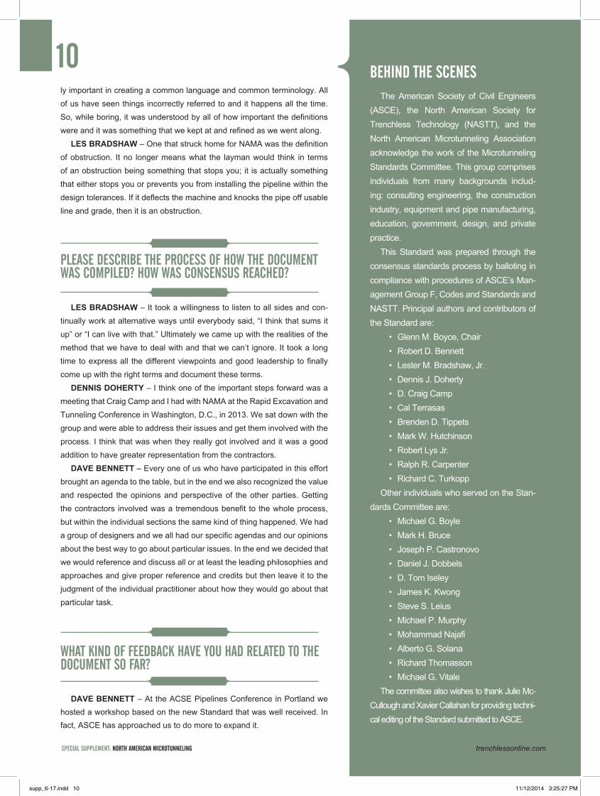
10The American Society of Civil Engineers
(ASCE), the North American Society for Trenchless Technology (NASTT), and the North American Microtunneling Association acknowledge the work of the Microtunneling Standards Committee. This group comprises individuals from many backgrounds includ-ing: consulting engineering, the construction industry, equipment and pipe manufacturing, education, government, design, and private practice.
This Standard was prepared through the consensus standards process by balloting in compliance with procedures of ASCE’s Man-agement Group F, Codes and Standards and NASTT. Principal authors and contributors of the Standard are:
• Glenn M. Boyce, Chair • Robert D. Bennett • Lester M. Bradshaw, Jr.• Dennis J. Doherty • D. Craig Camp• Cal Terrasas• Brenden D. Tippets• Mark W. Hutchinson• Robert Lys Jr.• Ralph R. Carpenter • Richard C. Turkopp
Other individuals who served on the Stan-dards Committee are:
• Michael G. Boyle • Mark H. Bruce • Joseph P. Castronovo• Daniel J. Dobbels • D. Tom Iseley • James K. Kwong• Steve S. Leius • Michael P. Murphy• Mohammad Najafi • Alberto G. Solana • Richard Thomasson • Michael G. Vitale
The committee also wishes to thank Julie Mc-Cullough and Xavier Callahan for providing techni-cal editing of the Standard submitted to ASCE.
bEHINd THE SCENES
supp_6-17.indd 10 11/12/2014 3:25:27 PM

11
tunnelingonline.com SPECIAL SUPPLEMENT: NORTH AMERICAN MICROTUNNELING
GLENN BOYCE – The workshop really helped provide a lot of exposure to the new Standard and we got a lot of positive feed-back from it. Basically it was a 4-hour ses-sion that went through the sections of the new Standard and highlighted some of the changes that were made and the reasons behind the changes. But the document is still in progress. When it gets published and gets into people’s hands it will start to have a bigger impact.
DENNIS DOHERTY – One thing I found interesting about it was that there was a representative from the railroad at the workshop in Portland. Railroads have historically been reluctant to accept new technologies but this individual was at the conference to specifically attend the micro-tunneling workshop. They want to be more progressive and understand what is hap-pening in the industry.
wHAT AbOUT THE INdUSTRY IN GENERAL? HOw dO YOU VIEw THE STATE Of THE INdUSTRY? HOw HAS IT EVOLVEd?
MARK HUTCHINSON – When Portland began microtunneling in the 1990s, there were just a few engineers around with ex-perience who could design the projects, and it was hard to get advice on what to be concerned about or specify. At that time, there were only a handful of contractors and they came with the machine they had with limited ability. Most projects ended with claims, and some projects didn’t get completed. The method was considered too risky or expensive to try from an own-er’s perspective.
Today there are more options when it
comes to hiring engineers, but still only a few good ones. The contractors are much more sophisticated; they bring engineers and innovative ideas. We also see con-tractors who are jack-and-bore contrac-tors who sell their work as microtunneling. I think the machines, and the contractors’ people have improved. The shafts and pipe continue to be a challenge. We often have general civil/structural guys design-ing shafts or placing design constraints on them. We see pipe that is not properly specified requiring testing.
The social requirements also contin-ue to increase in regard to allowed work hours, shielding operations from the pub-lic, settlement and vibration effects or per-ceived effects on structures, and unrealistic settlement requirements.
LES BRADSHAW – Right now the in-dustry is significantly overcapacity from the
supp_6-17.indd 11 11/12/2014 3:25:27 PM
SPECIAL SUPPLEMENT: NORTH AMERICAN MICROTUNNELING trenchlessonline.com
12
deep recession. We are still seeing bids where somebody comes in 10 to 30 per-cent low. It seems like desperation bidding is taking place. On one recent project, the low bidder was 25 percent cheaper than the second bidder and 40 percent below the engineer’s estimate. There is not a lot of room to work with and any issue could become a potential claim.
DAVE BENNETT – One the other hand, though, we have seen a couple of jobs where the bids were rejected because they were too high. In these particular instances I think it is a result of permitting and reg-ulatory agencies putting strenuous and burdensome requirements on the contrac-tors. The fact that the bids are coming in high should not come as a surprise where there are limitations such as reduced work hours, reduced noise levels, and oversight for all sorts of biological impacts and ar-chaeological artifacts. They add up, and
the regulators don’t seem to understand the impact they are having on this industry.
LES BRADSHAW – Another area I think we need to address is the confusion that exists among some owners and engi-neers between slurry microtunneling and the pilot tube method budgets. I have seen estimates for microtunneling that are 30 to 40 percent of what they should be. The es-timates must have been based on the pilot tube method.
DENNIS DOHERTY – The term ‘pilot tube microtunneling’ is often used today, but it is confusing. In the Standard it is re-ferred to as the ‘pilot tube method’ to avoid confusion. The pilot tube method is not mi-crotunneling.
DAVE BENNETT – One of the things we often fight, and lose, is unrealistically low estimates for open-cut as an alterna-tive to microtunneling. When you start out with an unrealistically low estimate for open-cut, there is no way you are going to be able to compete with a trenchless alter-native. The Owner looks at microtunneling at $2,000 per ft or $2,500 per ft, compared to unrealistically low open cut cost esti-mates which do not properly account for dewatering, and rule it out. But when the bids come in for open-cut with deep wells, they may understand that the trenchless option would have been competitive.
HOw dO YOU SEE THE fUTURE Of THE MARkET? wHAT CAN bE dONE TO HELP THE MICROTUNNELING INdUSTRY GROw?
MARK HUTCHINSON – I see more work in the cities due to constraints caused by streets full of utilities, ever increasing environmental issues with contaminated soil and groundwater, wetland restrictions, and requirements posed by DOTs on road-way restoration or traffic lane restrictions. I see jobs we used to specify as open-cut,
requiring microtunneling now. As part of a sewer pump station we are building right now, the pipe was required to be microtun-neled, even though it was only 25 ft deep, due to zoning restrictions.
DAVE BENNETT – I believe for micro-tunneling – and trenchless in general to grow – we need to educate regulatory and permitting agencies that often place crip-pling constraints on the projects. All of us want to do the right thing and protect the environment, but we need to find a balance and move forward. We are seeing a lot of jobs that are being killed right now because of over-regulation and permit conditions that are not practical.
LES BRADSHAW – Right now we see a water crisis in the West and mandated CSO programs in the East and Midwest that are driving underground work. Most of that is related to large storage structures but in three to five years there could be some mi-crotunneling work needed to feed the larger structures. The work is there, but it will take a while and will take continued funding.
DENNIS DOHERTY – One of the growth areas may be in the area of elec-trical transmission. While microtunneling has been typically used in gravity sewer systems, I am seeing it more on the power side. Microtunneling certainly gives you more options when you are working below the water table.
DAVE BENNETT – Growing the mar-ket takes efforts like the publication of the Standard, as well as the follow up educa-tion of all stakeholders. It is a slow process and it seems discouraging at times, but when we look back over 15 to 20 years we have certainly made progress. Progress is incremental, and we need to continue to educate, put together good projects with good contract documents and qualified contractors and allow them to use their in-novation. It is a step-by-step process, but I still believe that is how we do it.
JIM RUSH IS EdITOR Of TRENCHLESS TECHNOLOGY & TbM.
dENNIS dOHERTY
MARk HUTCHINSON
supp_6-17.indd 12 11/12/2014 3:25:28 PM
13
tunnelingonline.com SPECIAL SUPPLEMENT: NORTH AMERICAN MICROTUNNELING
It is often said that it takes cooperation and teamwork among all parties to complete a successful microtunneling project. Generally, this relates to the contractor, engineer and owner, but it is also true of the individual par-ties themselves – the contractor executives and field personnel or the project engineer and the home office. When all of these oars are rowing in the same direction, the challenges presented by Mother Nature can be overcome.
In an effort to recognize the individuals and companies that have worked toward successfully completing complicated projects and advanced the in-dustry, the Microtunneling Achievement Awards were created. The awards are presented annually at the Microtunneling Short Course in February. This year’s awards, which were established by course organizers Tim Coss, Micro-tunneling Inc., and Levent Ozdemir, Ozdemir Engineering, will be bestowed at the annual banquet on Thursday, Feb. 13, 2015, in Golden, Colo.
MICROTUNNELING ACHIEVEMENT AwARdSINdUSTRY LEAdERS TO RECEIVE HONORS AT MICROTUNNELING SHORT COURSE
fEATURE STORYPast winners of the Microtunneling Achievement Award:• Northwest Boring (2002)• Franco Coluccio, Frank Coluccio Construction Co.
(2004)• Glenn Boyce, Jacobs Associates (2006)• Dr. James Kwong, yogi Kwong Engineers (2007,
2013)• Stefan Trumpi-Althaus, Jack Control Inc. (2008)• Matt Roberts, Kiewit (2009)• Dennis Molvik, Northwest Boring (2011)• Rick Turkopp, Hobas (2012)• Gary Huber, Permalok (2012)• James W. Fowler Co. (2014)• Rene Inosanto, Frank Coluccio Construction Co.
(2015)• Greg Raines, MWH (2015)• Ward and Burke (2015)
MICROTUNNELING ACHIEVEMENT AwARd wINNERS
supp_6-17.indd 13 11/12/2014 3:25:29 PM
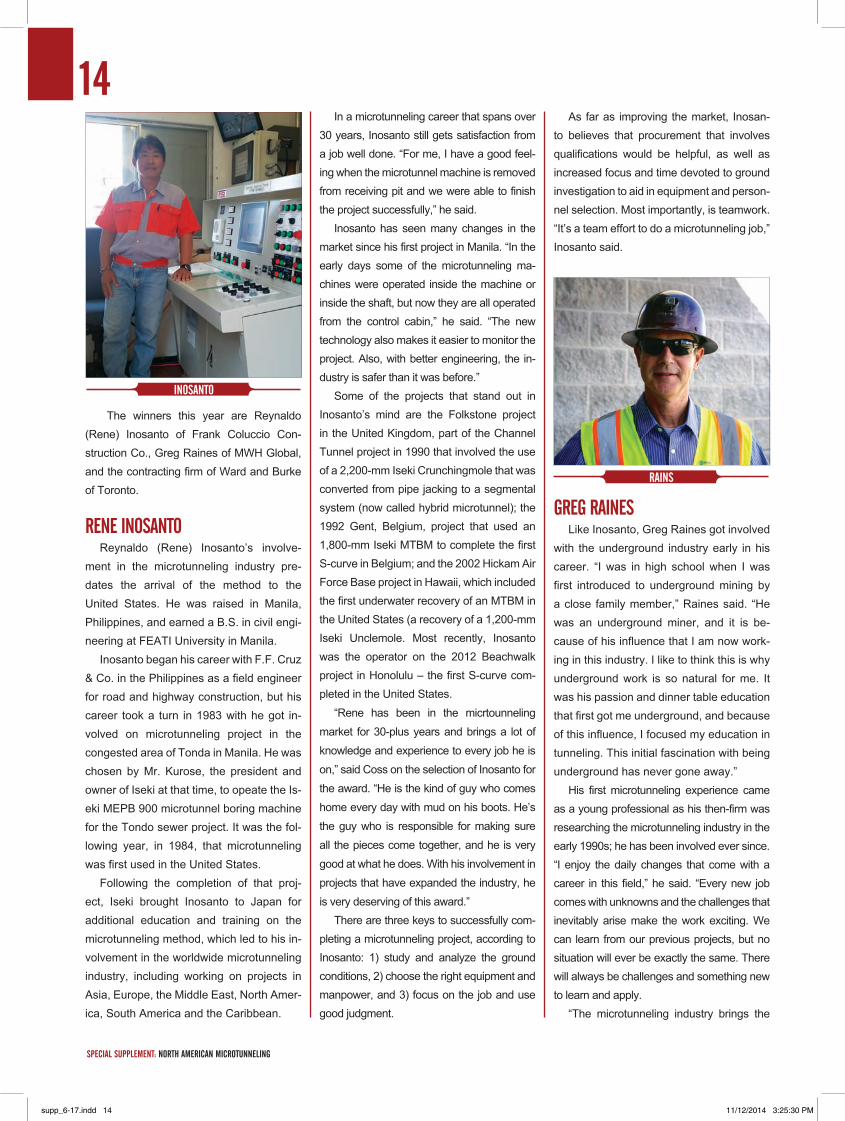
The winners this year are Reynaldo (Rene) Inosanto of Frank Coluccio Con-struction Co., Greg Raines of MWH Global, and the contracting firm of Ward and Burke of Toronto.
RENE INOSANTOReynaldo (Rene) Inosanto’s involve-
ment in the microtunneling industry pre-dates the arrival of the method to the United States. He was raised in Manila, Philippines, and earned a B.S. in civil engi-neering at FEATI University in Manila.
Inosanto began his career with F.F. Cruz & Co. in the Philippines as a field engineer for road and highway construction, but his career took a turn in 1983 with he got in-volved on microtunneling project in the congested area of Tonda in Manila. He was chosen by Mr. Kurose, the president and owner of Iseki at that time, to opeate the Is-eki MEPB 900 microtunnel boring machine for the Tondo sewer project. It was the fol-lowing year, in 1984, that microtunneling was first used in the United States.
Following the completion of that proj-ect, Iseki brought Inosanto to Japan for additional education and training on the microtunneling method, which led to his in-volvement in the worldwide microtunneling industry, including working on projects in Asia, Europe, the Middle East, North Amer-ica, South America and the Caribbean.
In a microtunneling career that spans over 30 years, Inosanto still gets satisfaction from a job well done. “For me, I have a good feel-ing when the microtunnel machine is removed from receiving pit and we were able to finish the project successfully,” he said.
Inosanto has seen many changes in the market since his first project in Manila. “In the early days some of the microtunneling ma-chines were operated inside the machine or inside the shaft, but now they are all operated from the control cabin,” he said. “The new technology also makes it easier to monitor the project. Also, with better engineering, the in-dustry is safer than it was before.”
Some of the projects that stand out in Inosanto’s mind are the Folkstone project in the United Kingdom, part of the Channel Tunnel project in 1990 that involved the use of a 2,200-mm Iseki Crunchingmole that was converted from pipe jacking to a segmental system (now called hybrid microtunnel); the 1992 Gent, Belgium, project that used an 1,800-mm Iseki MTBM to complete the first S-curve in Belgium; and the 2002 Hickam Air Force Base project in Hawaii, which included the first underwater recovery of an MTBM in the United States (a recovery of a 1,200-mm Iseki Unclemole. Most recently, Inosanto was the operator on the 2012 Beachwalk project in Honolulu – the first S-curve com-pleted in the United States.
“Rene has been in the micrtounneling market for 30-plus years and brings a lot of knowledge and experience to every job he is on,” said Coss on the selection of Inosanto for the award. “He is the kind of guy who comes home every day with mud on his boots. He’s the guy who is responsible for making sure all the pieces come together, and he is very good at what he does. With his involvement in projects that have expanded the industry, he is very deserving of this award.”
There are three keys to successfully com-pleting a microtunneling project, according to Inosanto: 1) study and analyze the ground conditions, 2) choose the right equipment and manpower, and 3) focus on the job and use good judgment.
As far as improving the market, Inosan-to believes that procurement that involves qualifications would be helpful, as well as increased focus and time devoted to ground investigation to aid in equipment and person-nel selection. Most importantly, is teamwork. “It’s a team effort to do a microtunneling job,” Inosanto said.
GREG RAINESLike Inosanto, Greg Raines got involved
with the underground industry early in his career. “I was in high school when I was first introduced to underground mining by a close family member,” Raines said. “He was an underground miner, and it is be-cause of his influence that I am now work-ing in this industry. I like to think this is why underground work is so natural for me. It was his passion and dinner table education that first got me underground, and because of this influence, I focused my education in tunneling. This initial fascination with being underground has never gone away.”
His first microtunneling experience came as a young professional as his then-firm was researching the microtunneling industry in the early 1990s; he has been involved ever since. “I enjoy the daily changes that come with a career in this field,” he said. “Every new job comes with unknowns and the challenges that inevitably arise make the work exciting. We can learn from our previous projects, but no situation will ever be exactly the same. There will always be challenges and something new to learn and apply.
“The microtunneling industry brings the
14
SPECIAL SUPPLEMENT: NORTH AMERICAN MICROTUNNELING trenchlessonline.com
INOSANTO
RAINS
supp_6-17.indd 14 11/12/2014 3:25:30 PM
excitement of technological advancements as well. Completing an entire project through remote control is a unique and cutting-edge. These projects put me and my team on the cusp of innovation. We are a part of the fu-ture.”
Like Inosanto, Raines has seen numer-ous developments in the field of microtunnel-ing. “There have been significant changes in the industry since I first joined, from the guidance systems to the separation systems and now curved drives are finally happening in the United States,” he said. “The design of cutterhead technology is a major change also, with disk cutters for rock and systems to handle hard sticky clay, which expands the range of ground conditions we can apply the technology to.”
So what does Raines see as the keys to success? “I believe successful comple-tion always begins with early planning and investigation,” he said. “This starts with an understanding of the geotechnical character-
izations, and from there, the selection of the appropriate equipment. After planning, the key is experience and a good contract. Any difficult job is going to need flexibility and a contractual means to adjust to uncertainties, as well as a strong team with the experience to know how to handle these inevitable un-known difficulties.”
Despite its growth and maturation, micro-tunneling still has work to do if it is going to expand. “Our industry is using cutting-edge technology and is achieving amazing things,” he said. “However, across the tunneling in-dustry, I think we have to be more realistic and manage expectations better with our clients. The industry tends to be too optimistic of what can be achieved within a set time and budget. I think a better understanding of the true time-tables and budgets will significantly help the industry in the future.
“Microtunneling was hit hard by the Great Recession, because local municipalities were unable to fund much needed infra-
structure projects. However, now that we are coming out of that, I expect the market to pick up as long as we deliver to our custom-ers, as promised.”
Raines’ baskground and impact on the market make him an ideal candidate for the award, Coss said. “Greg has always promot-ed the industry with common-sense engineer-ing,” he said. “Some engineers don’t under-stand what is going on in the field, but Greg understands the geology and the construction aspects – he can balance what is practical and what the owner needs.”
wARd ANd bURkEIn 2011, Ward and Burke Construction,
a heavy civil contracting company based in Ireland, re-introduced microtunneling to To-ronto with the completion of the Gore Road project. That project involved the construction of a new 1,200-mm ID sanitary sewer pipe running directly under an existing 1,800-mm concrete pressure pipe water transmission
15
tunnelingonline.com SPECIAL SUPPLEMENT: NORTH AMERICAN MICROTUNNELING
supp_6-17.indd 15 11/12/2014 3:25:31 PM

line and an existing creek at Gore Road, in Brampton, Ont. Because of the presence of groundwater, cohesionless ground and the 1.5-m clearance between the two lines, settlement to the transmission line was a sig-nificant threat and traditional open-face tun-neling methods were not suitable.
Due to the uniqueness of the project and limited options, Ward and Burke was able to bring microtunneling technology back to the area. The successful completion of the project then opened the door for additional projects in the area. The completion of each subsequent project then began opening the door a little wider.
“Some clients and consultants were fa-miliar with the technology, but until some-body actually completed a project, no one was willing to specify it as microtunneling,” said John Grennan, a founding member of Ward and Burke’s Canadian operations with Robert Ward. “We started with some small, 10-m long tunnels, then 20 m, then up to 100 m and more. So the more tunnels that we did and the longer they got, everyone built up confidence, but it took a lot of jobs to build up that confidence. ”
Ward and Burke was founded in Ireland in 2001 by Padraig Burke, Robert Ward and Michael Ward as a construction company engaged in heavy civil construction, includ-ing tunnels, pipelines, road and bridges. Ward and Burke expanded to the U.K. mar-ket in 2008 before entering the Canadian market in 2011.
Some of Ward and Burke’s notable proj-ects include: the Keswick WPCP Effluent Out-
fall Expansion, the first-ever combined vertical and horizontal curve microtunnel constructed in North America, as well as the first curved drive in Canada and the first wet recovery of an MTBM in Canada; and the Elgin Mills Road Waterman, the longest, curved micro-tunnel ever constructed in North America. The project was completed in October 2013.
Grennan says the success of Ward and Burke is attributable to a number of factors. First and foremost is a keeping the focus on doing the job right. “Our No. 1 goal is keep the client happy at all times and doing good work,” he said.
Ward and Burke is able to achieve this goal by relying on a technically led work-force. “All of our owners, directors, project managers and site managers are fully quali-fied civil engineers. They have graduated from some of the best universities around the world, including Massachusetts Institute of Technology (MIT),” he said. “We currently fund research programs at MIT, University of Western Ontario (UWO), and National Uni-versity of Ireland Galway (NUIG) that focus on solving field problems.
“Our philosophy is to put our best people closest to the work where they are able to evaluate all the data and risk as it hap-pens, so that they can react before a prob-lem happens. We have also been fortunate to acquire excellent operators, technicians, mechanics and electricians, who are all im-portant to the operation.”
Grennan credits the Microtunneling Short Course with helping the company find its di-rection in North America. “In 2010, Ward and Burke went to the Short Course for the first time with the aim to learn and improve from industry leaders, and we were not disappoint-ed,” he said. “We were highly impressed by the caliber and knowledge level of the vari-ous presenters and attendees at the event. The Microtunneling Short Course set new benchmarks and targets for our company to achieve. We still believe we have a lot of work to do to reach these benchmarks. Therefore, we are honored, privileged, and humbled to receive this award from this group.”
SPECIAL SUPPLEMENT: NORTH AMERICAN MICROTUNNELING trenchlessonline.com
16
Established at the Colorado School of Mines in 1994, the Microtunneling Short Course is recognized as the lead-ing instructional venue for microtunnel-ing worldwide. Since its introduction, well over 2,000 professionals, ranging from contractors and engineers to own-er agency representatives, have gone through the course.
The Microtunneling Short Course was established at a time when the method was still gaining acceptance in the utility construction industry, and has helped grow the market through education and understanding. It has continued to evolve along with the industry, offering high-level education on leading-edge technologies and topics. Since that time, the art and sci-ence of microtunneling has changed dramatically, with projects being com-pleted in North America today that would not have been considered even a decade ago.
The 2015 Microtunneling Short Course, which will be held Feb. 10-12 with a one-day Pilot Tube seminar on offered on Feb. 9, covers the latest in emerging technologies from this grow-ing field. With more and more demand for underground services in urban ar-eas, the need to use minimally invasive construction techniques like microtun-neling will only increase.
The Microtunneling Short Course is a three-day, intensive course pre-sented by a panel of international ex-perts and organized by Prof. Levent Ozdemir of Ozdemir Engineering and Timothy Coss of Microtunneling Inc. It will be held at the Green Center on the campus of the Colorado School of Mines in Golden, 40 miles west of Den-ver International Airport.
MICROTUNNELING SHORT COURSE: THE INdUSTRY LEAdER IN EdUCATION
wARd & bURkE CREw
supp_6-17.indd 16 11/12/2014 3:25:33 PM
tunnelingonline.com SPECIAL SUPPLEMENT: NORTH AMERICAN MICROTUNNELING
17
The course covers all aspects of micto-tunneling including site investigation, ground stabilization, shaft construction, pipe consid-erations, microtunneling and slurry equip-ment advances, case studies, and more. It is intended for public works and utility officials, engineers, planners, managers, contractors, and equipment manufacturers involved in any phase of trenchless technology.
Another attraction of the Microtunneling Short Course is the presentation of the Mi-crotunneling Achievement Award winners,
which are bestowed on the companies or individuals who have made a lasting impact on the microtunneling industry. This year the awards will be given to Rene Inosanto of Frank Coluccio Construction Co., Greg Raines of MWH, and the contracting firm of Ward and Burke.
The winners will be presented during an evening banquet on Thursday, Feb. 12 at the Golden Hotel. In addition to the awards pre-sentation, the banquet includes a reception and guest speaker, and serves as a network-
ing event to cap off the course. If you are involved with microtunneling or
are planning to be involved, the Microtun-neling Short Course is a must-attend event to obtain the latest technical information to ensure a successful project. The course is presented in cooperation with Microtunneling Inc., Trenchless Technology magazine and the Colorado School of Mines’ Office of Spe-cial Programs and Continuing Education. To register for the course visit: http://csmspace.com/events/microtunnel
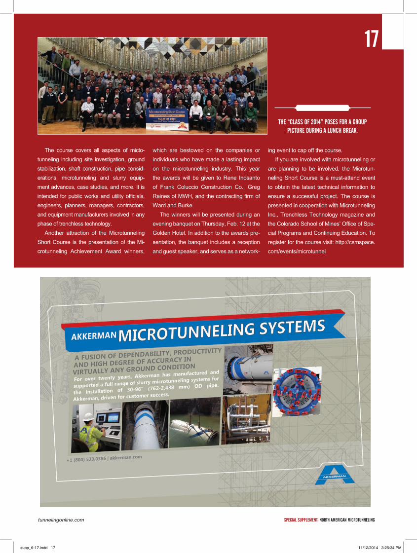
THE “CLASS Of 2014” POSES fOR A GROUP PICTURE dURING A LUNCH bREAk.
17
supp_6-17.indd 17 11/12/2014 3:25:34 PM
18
SPECIAL SUPPLEMENT: NORTH AMERICAN MICROTUNNELING trenchlessonline.com
FEATURE STORY
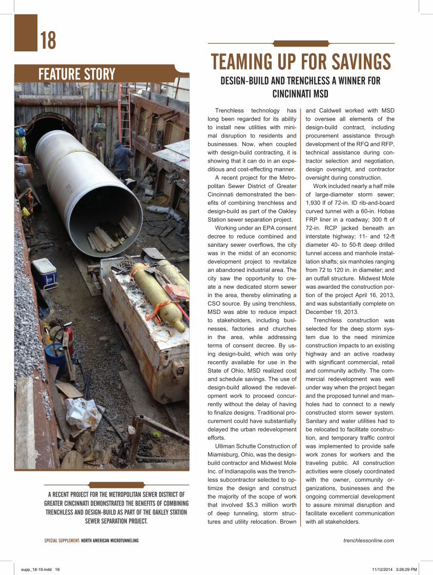
A RECENT PROjECT FOR THE METROPOLITAN SEwER DISTRICT OF GREATER CINCINNATI DEMONSTRATED THE bENEFITS OF COMbINING TRENCHLESS AND DESIGN-bUILD AS PART OF THE OAkLEY STATION
SEwER SEPARATION PROjECT.
Trenchless technology has long been regarded for its ability to install new utilities with mini-mal disruption to residents and businesses. Now, when coupled with design-build contracting, it is showing that it can do in an expe-ditious and cost-effecting manner.
A recent project for the Metro-politan Sewer District of Greater Cincinnati demonstrated the ben-efits of combining trenchless and design-build as part of the Oakley Station sewer separation project.
Working under an EPA consent decree to reduce combined and sanitary sewer overflows, the city was in the midst of an economic development project to revitalize an abandoned industrial area. The city saw the opportunity to cre-ate a new dedicated storm sewer in the area, thereby eliminating a CSO source. By using trenchless, MSD was able to reduce impact to stakeholders, including busi-nesses, factories and churches in the area, while addressing terms of consent decree. By us-ing design-build, which was only recently available for use in the State of Ohio, MSD realized cost and schedule savings. The use of design-build allowed the redevel-opment work to proceed concur-rently without the delay of having to finalize designs. Traditional pro-curement could have substantially delayed the urban redevelopment efforts.
Ulliman Schutte Construction of Miamisburg, Ohio, was the design-build contractor and Midwest Mole Inc. of Indianapolis was the trench-less subcontractor selected to op-timize the design and construct the majority of the scope of work that involved $5.3 million worth of deep tunneling, storm struc-tures and utility relocation. Brown
and Caldwell worked with MSD to oversee all elements of the design-build contract, including procurement assistance through development of the RFQ and RFP, technical assistance during con-tractor selection and negotiation, design oversight, and contractor oversight during construction.
Work included nearly a half mile of large-diameter storm sewer; 1,930 lf of 72-in. ID rib-and-board curved tunnel with a 60-in. Hobas FRP liner in a roadway; 300 ft of 72-in. RCP jacked beneath an interstate highway; 11- and 12-ft diameter 40- to 50-ft deep drilled tunnel access and manhole instal-lation shafts; six manholes ranging from 72 to 120 in. in diameter; and an outfall structure. Midwest Mole was awarded the construction por-tion of the project April 16, 2013, and was substantially complete on December 19, 2013.
Trenchless construction was selected for the deep storm sys-tem due to the need minimize construction impacts to an existing highway and an active roadway with significant commercial, retail and community activity. The com-mercial redevelopment was well under way when the project began and the proposed tunnel and man-holes had to connect to a newly constructed storm sewer system. Sanitary and water utilities had to be relocated to facilitate construc-tion, and temporary traffic control was implemented to provide safe work zones for workers and the traveling public. All construction activities were closely coordinated with the owner, community or-ganizations, businesses and the ongoing commercial development to assure minimal disruption and facilitate excellent communication with all stakeholders.
TEAMING UP FOR SAvINGSDESIGN-bUILD AND TRENCHLESS A wINNER FOR
CINCINNATI MSD
supp_18-19.indd 18 11/12/2014 3:26:29 PM
19
tunnelingonline.com SPECIAL SUPPLEMENT: NORTH AMERICAN MICROTUNNELING
Geotechnical investigation showed that the tunnel would be constructed in relatively dry, stiff silty clays with occasional seams of perched water. Midwest Mole modified an Akkerman 720 TBM by adding self-contained hydraulics and an extended conveyor that allowed the use of three muck cars to complete one 4-ft tunnel set per muck cycle. This TBM was used to steer a radius section of tunnel that terminated where the TBM inter-sected the one of two deep shafts constructed using a drilled shaft lined with a 10-ft diameter grouted corrugated metal pipe. The tunnel crew navigated the 87-ft, 5-in. OD TBM through the center of a 120-in. OD manhole shaft. A standard closed-face Akkerman 720 TBM and SP 400 ton jacking system was used for the 300 ft of 72-in. RCP highway crossing.
The project included several technical challenges. The 1,930 ft of tunnel was constructed in a busy roadway with one 50-ft work shaft, two small-diameter, drilled CMP-lined deep access shafts and one 25-ft deep receiving pit. The small-diameter pits were used for the installation of precast storm manholes with 60-in. FRP lined through them. Small drilled shafts were necessary to minimize traffic disruption and utility relocation. These two man-holes also had to connect to the newly constructed site drainage system that was already installed and temporarily connected to the existing combined sewer. One of these connections required jacking a 72-in. steel casing at a depth of 25 ft from inside an 11-ft diameter shaft to connect to a 48-in. storm line.
Other challenging aspects included the discovery of a buried
building in the path of the proposed 72-in. RCP tunnel that was to be the system outfall. This obstruction was discovered while con-structing the jacking pit and the project had to be redesigned by moving the proposed crossing within a very limited working area. The lower section of the project was redesigned while the upper end of the system continued to be constructed. Had this been a traditional design-bid-build project, the entire project would have been stopped until the changed condition was recognized and a new alignment was determined and designed, causing delays and associated costs.
Design-build contacting allowed the project to proceed while portions were redesigned with minimal cost and zero schedule impact. There were other instances where unexpected conditions posed challenges. In each case, the high degree of trust between the design-build team and the owner allowed the best solutions to be proposed and accepted rapidly.
Overall, the project proved a successful marriage of trenchless technology, design-build contracting and excellent project execu-tion, which resulted in a very satisfied group of stakeholders who saved time and money who while proceeding with an ambitious redevelopment project while simultaneously meeting consent de-cree requirements. The design-build implementation was estimat-ed to have saved more than 20% of the construction cost of $12.2 million, and saved 13 months off of the schedule. It was named a Trenchless Technology magazine 2014 Projects of the Year Hon-orable Mention for the New Installation category.
supp_18-19.indd 19 11/12/2014 3:26:30 PM
SPECIAL SUPPLEMENT: NORTH AMERICAN MICROTUNNELING trenchlessonline.com
20
FEATURE STORY
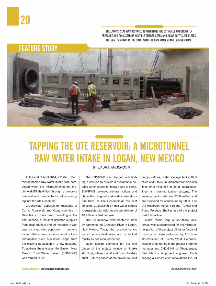
At the end of April 2014, a 236-lf., 60-in. microtunneled raw water intake was com-pleted when the microtunnel boring ma-chine (MTBM) drilled through a concrete headwall and tremmie block before emerg-ing into the Ute Reservoir.
Groundwater supplies for residents of Curry, Roosevelt and Quay counties in New Mexico have been dwindling in the past decade, a result of depleted supplies from local aquifers and an increase in well taps by a growing population. It became evident that current sources could not ac-commodate even sustained usage from the existing population in a few decades. To address these issues, the Eastern New Mexico Rural Water System (ENMRWS) was formed in 2010.
The ENMRWS was charged with find-ing a solution to provide a sustainable po-table water source for many years to come. ENMRWS reviewed several options and chose the design of a lakeside intake struc-ture from the Ute Reservoir as the best solution. Capitalizing on this water source is suspected to yield an annual delivery of 16,450 acre feet per year.
The Ute Reservoir was created in 1959 by damming the Canadian River in Logan, New Mexico. Today, the reservoir serves as a tourist’s destination and is flanked mostly by seasonal properties.
Major design elements for the first phase of the project include an intake structure, intake tunnel and pump forebay shaft. Future phases of the project will add
pump stations, water storage tanks, 87.5 miles of 30- to 54-in. diameter transmission lines, 94.8 miles of 8- to 36-in. lateral pipe-lines, and communication systems. The entire project costs are $550 million and are projected for completion by 2033. The Ute Reservoir Intake Screens, Tunnel and Pump Forebay Shaft phase of the project cost $14 million.
Nada Pacific Corp. of Caruthers, Cali-fornia, was subcontracted for the microtun-nel portion of the project. All other facets of construction were performed by ASI Con-structors Inc. of Pueblo West, Colorado. Occam Engineering is the project program manager and CH2M Hill of Albuquerque, New Mexico, is project engineer. Engi-neering & Construction Innovations Inc., of
TAPPING THE UTE RESERvOIR: A MICROTUNNEL RAw wATER INTAkE IN LOGAN, NEw MExICO
By LAURA ANdERSON
THE LAUNCH SEAL wAS dESIGNEd TO wITHSTANd THE ESTIMATEd GROUNdwATER PRESSURE ANd CONSISTEd OF MULTIPLE RUbbER SEALS ANd HEAvY-dUTY SLIdE PLATES.
THE SEAL IS SHOwN IN THE SHAFT wITH THE AkkERMAN MT460 jACkING FRAME.
supp_20-23.indd 20 11/12/2014 3:31:50 PM
tunnelingonline.com SPECIAL SUPPLEMENT: NORTH AMERICAN MICROTUNNELING
21Oakdale, Minnesota, a sister company to ASI, provided expertise for the specialized drill-and-blast operations. ASI Marine Ser-vices, another sister company to ASI, pro-vided professional services, personnel and equipment for the underwater construction.
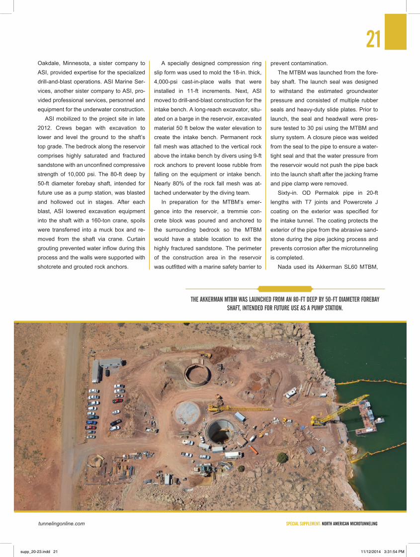
ASI mobilized to the project site in late 2012. Crews began with excavation to lower and level the ground to the shaft’s top grade. The bedrock along the reservoir comprises highly saturated and fractured sandstone with an unconfined compressive strength of 10,000 psi. The 80-ft deep by 50-ft diameter forebay shaft, intended for future use as a pump station, was blasted and hollowed out in stages. After each blast, ASI lowered excavation equipment into the shaft with a 160-ton crane, spoils were transferred into a muck box and re-moved from the shaft via crane. Curtain grouting prevented water inflow during this process and the walls were supported with shotcrete and grouted rock anchors.
A specially designed compression ring slip form was used to mold the 18-in. thick, 4,000-psi cast-in-place walls that were installed in 11-ft increments. Next, ASI moved to drill-and-blast construction for the intake bench. A long-reach excavator, situ-ated on a barge in the reservoir, excavated material 50 ft below the water elevation to create the intake bench. Permanent rock fall mesh was attached to the vertical rock above the intake bench by divers using 9-ft rock anchors to prevent loose rubble from falling on the equipment or intake bench. Nearly 80% of the rock fall mesh was at-tached underwater by the diving team.
In preparation for the MTBM’s emer-gence into the reservoir, a tremmie con-crete block was poured and anchored to the surrounding bedrock so the MTBM would have a stable location to exit the highly fractured sandstone. The perimeter of the construction area in the reservoir was outfitted with a marine safety barrier to
prevent contamination. The MTBM was launched from the fore-
bay shaft. The launch seal was designed to withstand the estimated groundwater pressure and consisted of multiple rubber seals and heavy-duty slide plates. Prior to launch, the seal and headwall were pres-sure tested to 30 psi using the MTBM and slurry system. A closure piece was welded from the seal to the pipe to ensure a water-tight seal and that the water pressure from the reservoir would not push the pipe back into the launch shaft after the jacking frame and pipe clamp were removed.
Sixty-in. Od Permalok pipe in 20-ft lengths with T7 joints and Powercrete J coating on the exterior was specified for the intake tunnel. The coating protects the exterior of the pipe from the abrasive sand-stone during the pipe jacking process and prevents corrosion after the microtunneling is completed.
Nada used its Akkerman SL60 MTBM,
THE AkkERMAN MTbM wAS LAUNCHEd FROM AN 80-FT dEEP bY 50-FT dIAMETER FOREbAY SHAFT, INTENdEd FOR FUTURE USE AS A PUMP STATION.
supp_20-23.indd 21 11/12/2014 3:31:54 PM
SPECIAL SUPPLEMENT: NORTH AMERICAN MICROTUNNELING trenchlessonline.com
MT460 jacking frame, control container and bentonite pump with a derrick Flo Line Primer slurry separation plant for microtunnel-ing operations. The MTBM was outfitted with a bulkhead to seal off the sensitive internal components of the MTBM from water damage when retrieved from the reservoir. The MTBM cutterhead was equipped with disc cutters, drag teeth, and picks to meet the 15,000-psi rock cutter baseline.
Nada mobilized on site on March 11, 2014. After a few minor delays, crews launched the MTBM on April 7, 2014, and had to contend with constant wind, sometimes as strong as 70 mph, dur-ing their six weeks onsite. They experienced an average produc-tion rate of 34 lf per 11-hour shift, and reported a peak installation rate of 52 lf in one shift.
Prior to launch, crews welded a bulkhead in the first pipe behind the MTBM. After retrieval of the MTBM, the bulkhead served as a watertight seal between the reservoir and the jacking shaft to allow for simultaneous work on both ends of the project. After the MTBM drilled through the headwall, the 5-ft space between the back end of the MTBM and the bulkhead was closed and pressure tested before the MTBM was removed from the pipe string. The bulkhead would later be removed by ASI when the complete intake system was ready for operation.
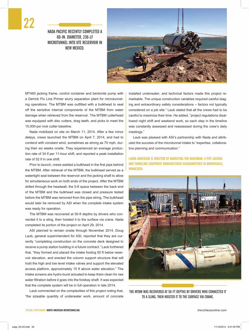
The MTBM was recovered at 50-ft depths by drivers who con-nected it to a sling, then hoisted it to the surface via crane. Nada completed its portion of the project on April 29, 2014.
ASI planned to remain onsite through November 2014. doug Laub, general superintendent for ASI, reported that they are cur-rently “completing construction on the concrete deck designed to receive a pump station building in a future contract.” Laub furthered that, “they formed and placed the intake footing 50 ft below reser-voir elevation, and erected the column support structure that will hold the high and low level intake valves and support the elevated access platform, approximately 15 ft above water elevation.” The intake screens are hydro-burst actuated to keep them clean for raw water filtration before it goes into the forebay shaft. It was expected that the complete system will be in full operation in late 2014.
Laub commented on the complexities of this project noting that, “the sizeable quantity of underwater work, amount of concrete
installed underwater, and technical factors made this project re-markable. The unique construction variables required careful stag-ing and extraordinary safety considerations – factors not typically considered on a job site.” Laub stated that all the crews had to be careful to maximize their time. He added, “project regulations disal-lowed night shift and weekend work, so each step in the timeline was constantly assessed and reassessed during the crew’s daily meetings.”
Laub was pleased with ASI’s partnership with Nada and attrib-uted the success of the microtunnel intake to “expertise, collabora-tive planning and communication.”
LAURA ANdERSON IS dIRECTOR OF MARkETING FOR AkkERMAN, A PIPE jACkING ANd TUNNELING EqUIPMENT MANUFACTURER HEAdqUARTEREd IN bROwNSdALE, MINNESOTA.
22NAdA PACIFIC RECENTLY COMPLETEd A
60-IN. dIAMETER, 236-LF MICROTUNNEL INTO UTE RESERvOIR IN
NEw MExICO.
THE MTbM wAS RECOvEREd AT 50-FT dEPTHS bY dRIvERS wHO CONNECTEd IT TO A SLING, THEN HOISTEd IT TO THE SURFACE vIA CRANE.
supp_20-23.indd 22 11/12/2014 3:31:55 PM

supp_20-23.indd 23 11/12/2014 3:31:57 PM
SPECIAL SUPPLEMENT: NORTH AMERICAN MICROTUNNELING trenchlessonline.com
While microtunneling is never “routine” – careful planning and atten-tion to detail are prerequisites of every successful project – the reality is that some jobs are more difficult than others. Mixed faced conditions, abrasive rock and strict requirements for line and grade accuracy can challenge even the most seasoned professionals.
In a recent microtunneling project in Pennsylvania, the contractor faced all three of these difficulties in a single run, which also included shallow cover as it passed below the Schuylkill River in Reading.
As part of the project, crews from Bradshaw Construction of Elder-sburg, Maryland, completed a 436-ft bore through mixed face condi-tions, including rock that measured 34,300 psi. To complicate matters, crews had to hit a small-diameter (9-ft) receiving shaft, which meant that accuracy of plus/minus 1.5 in. was needed to allow recovery of the microtunnel boring machine (MTBM). Given the potential for deflec-tion due to the mixed face and hard rock conditions, this presented a significant challenge.
PROjECT BACkGROUNdWith a population of just less than 100,000, Reading is the fifth-larg-
est city in Pennsylvania. Like many other cities in the United States, Reading is in the process of updating its sewer system as part of an EPA consent decree. Part of that work includes a $9.8 million project that includes the microtunneled crossing of the Schuylkill to construct a new sewer main from the City’s pump station at 6th and Canal Streets to the wastewater treatment plant (WWTP) located on Fritz Island.
The 6th and Canal Pump Station conveys about 75 percent of the flowing heading the WWTP. The current pipeline from the pump station to the plant was constructed about 60 years ago, and has experienced recent breaks. The new pipeline comprises about 7,000 lf of 42-in. diameter ductile iron force main and will allow the old main to be taken out of service for repair. Additional benefits of the new main include a redundant supply for the future, increased capacity for future growth, and lower operating pres-sures when both pipelines are in operation.
Most of the new pipeline was constructed by open-cut, but micto-tunneling was selected to install the 436-ft reach under the Schuylkill River. The design called for construction of shafts on either side of the river, with a 60-in. casing installed to host the 42-in. pipeline. Entech Engineering of Reading was the project designer and Hill International Inc. of Philadelphia was the project manager. Pact Construction of Rin-goes, New Jersey, was the general contractor.
Several challenges were associated with the construction of the jacking shaft, including: the presence of contaminated groundwater, which restricted dewatering; the deteriorated condition of the existing pipeline, which limited blasting for shaft excavation in rock; the poten-tial for flooding due to the proximity to the river; constraints related to the keeping operations at the pump station unimpeded; and limited shaft support options due to the geologic conditions.
FORGING AHEAdTo minimize groundwater inflow and dewatering, a secant pile
shaft 32-ft in diameter and 40 ft deep was constructed. Drilled piles were viewed as preferential to steel sheeting because of the rock conditions near the pipeline invert. Once the piles were drilled and the shaft excavated subaqueously, the plan was the install a con-crete tremie plug at the shaft bottom.
During shaft construction, however, it was discovered that the top of rock was higher than expected. This was despite an extensive geo-technical investigation program that included 12 borings, nine of which were within the river, along the 436-ft bore. Due to the presence of
By JIM RUSH
BRAdSHAw CONSTRUCTION COMPLETES dIFFICULT CROSS-ING OF THE SCHUyLkILL RIvER IN REAdING, PENNSyLvANIA
24
OvERCOMING THE CHALLENGES OF MIxEd FACE MICROTUNNELING
FEATURE STORy
supp_24-31.indd 24 11/12/2014 3:33:58 PM
tunnelingonline.com SPECIAL SUPPLEMENT: NORTH AMERICAN MICROTUNNELING
25rock requiring mechanical excavation, a reinforced concrete slab was constructed, which minimized the amount of rock excavation needed. A concrete thrust block was installed to accommodate the MTBM and 520-metric ton jacking frame.
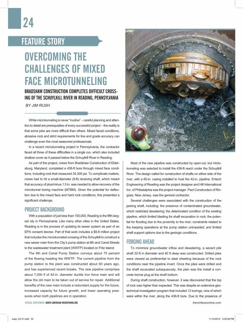
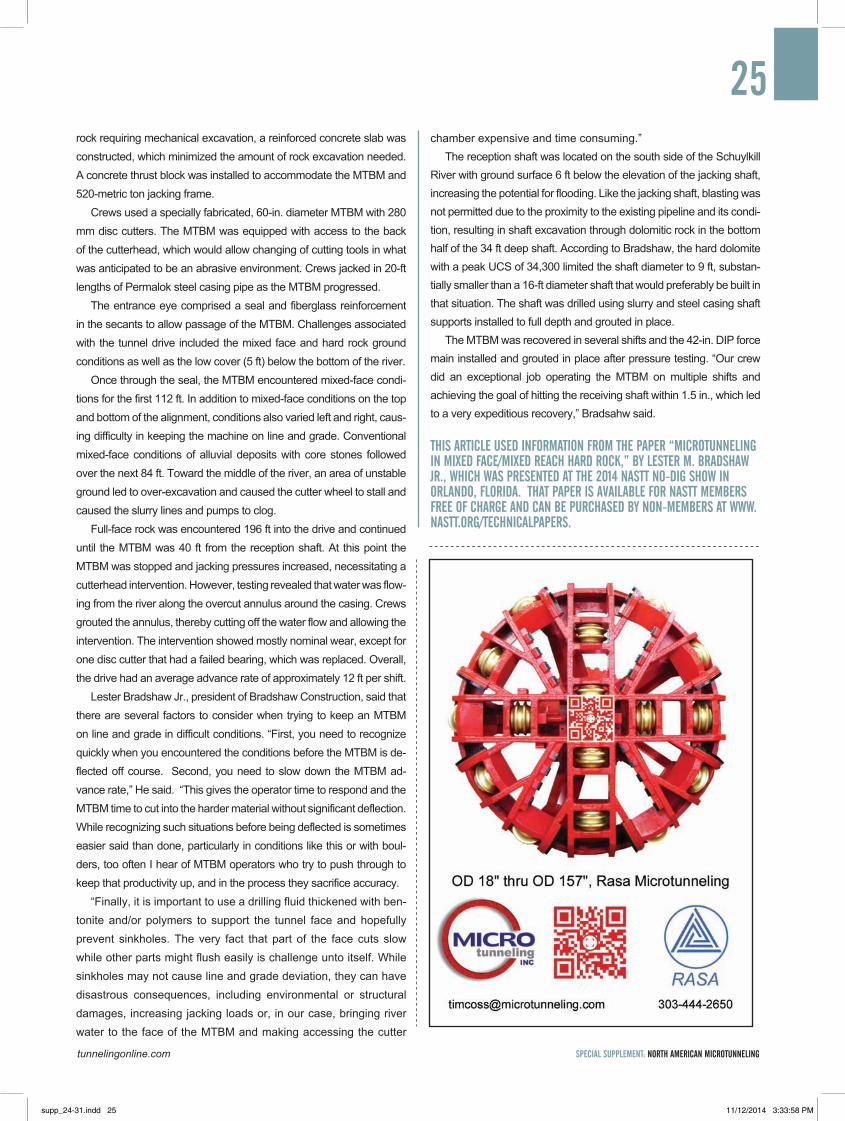
Crews used a specially fabricated, 60-in. diameter MTBM with 280 mm disc cutters. The MTBM was equipped with access to the back of the cutterhead, which would allow changing of cutting tools in what was anticipated to be an abrasive environment. Crews jacked in 20-ft lengths of Permalok steel casing pipe as the MTBM progressed.
The entrance eye comprised a seal and fiberglass reinforcement in the secants to allow passage of the MTBM. Challenges associated with the tunnel drive included the mixed face and hard rock ground conditions as well as the low cover (5 ft) below the bottom of the river.
Once through the seal, the MTBM encountered mixed-face condi-tions for the first 112 ft. In addition to mixed-face conditions on the top and bottom of the alignment, conditions also varied left and right, caus-ing difficulty in keeping the machine on line and grade. Conventional mixed-face conditions of alluvial deposits with core stones followed over the next 84 ft. Toward the middle of the river, an area of unstable ground led to over-excavation and caused the cutter wheel to stall and caused the slurry lines and pumps to clog.
Full-face rock was encountered 196 ft into the drive and continued until the MTBM was 40 ft from the reception shaft. At this point the MTBM was stopped and jacking pressures increased, necessitating a cutterhead intervention. However, testing revealed that water was flow-ing from the river along the overcut annulus around the casing. Crews grouted the annulus, thereby cutting off the water flow and allowing the intervention. The intervention showed mostly nominal wear, except for one disc cutter that had a failed bearing, which was replaced. Overall, the drive had an average advance rate of approximately 12 ft per shift.
Lester Bradshaw Jr., president of Bradshaw Construction, said that there are several factors to consider when trying to keep an MTBM on line and grade in difficult conditions. “First, you need to recognize quickly when you encountered the conditions before the MTBM is de-flected off course. Second, you need to slow down the MTBM ad-vance rate,” He said. “This gives the operator time to respond and the MTBM time to cut into the harder material without significant deflection. While recognizing such situations before being deflected is sometimes easier said than done, particularly in conditions like this or with boul-ders, too often I hear of MTBM operators who try to push through to keep that productivity up, and in the process they sacrifice accuracy.
“Finally, it is important to use a drilling fluid thickened with ben-tonite and/or polymers to support the tunnel face and hopefully prevent sinkholes. The very fact that part of the face cuts slow while other parts might flush easily is challenge unto itself. While sinkholes may not cause line and grade deviation, they can have disastrous consequences, including environmental or structural damages, increasing jacking loads or, in our case, bringing river water to the face of the MTBM and making accessing the cutter
chamber expensive and time consuming.” The reception shaft was located on the south side of the Schuylkill
River with ground surface 6 ft below the elevation of the jacking shaft, increasing the potential for flooding. Like the jacking shaft, blasting was not permitted due to the proximity to the existing pipeline and its condi-tion, resulting in shaft excavation through dolomitic rock in the bottom half of the 34 ft deep shaft. According to Bradshaw, the hard dolomite with a peak UCS of 34,300 limited the shaft diameter to 9 ft, substan-tially smaller than a 16-ft diameter shaft that would preferably be built in that situation. The shaft was drilled using slurry and steel casing shaft supports installed to full depth and grouted in place.
The MTBM was recovered in several shifts and the 42-in. DIP force main installed and grouted in place after pressure testing. “Our crew did an exceptional job operating the MTBM on multiple shifts and achieving the goal of hitting the receiving shaft within 1.5 in., which led to a very expeditious recovery,” Bradsahw said.
THIS ARTICLE USEd INFORMATION FROM THE PAPER “MICROTUNNELING IN MIxEd FACE/MIxEd REACH HARd ROCk,” By LESTER M. BRAdSHAw jR., wHICH wAS PRESENTEd AT THE 2014 NASTT NO-dIG SHOw IN ORLANdO, FLORIdA. THAT PAPER IS AvAILABLE FOR NASTT MEMBERS FREE OF CHARGE ANd CAN BE PURCHASEd By NON-MEMBERS AT www.NASTT.ORG/TECHNICALPAPERS.
supp_24-31.indd 25 11/12/2014 3:33:58 PM
SPECIAL SUPPLEMENT: NORTH AMERICAN MICROTUNNELING trenchlessonline.com
BRAdSHAw CONSTRUCTION CORP. Lester M. Bradshaw, President 173 West Liberty Rd.. Eldersburg, MD 21784 United States 410-970-8300 [email protected] www.bradshawcc.com Large Diameter Tunneling, Microtunneling, Pipe Jacking, Shafts, Tunneling-Large Diameter
BRH-GARvER CONSTRUCTIONPeck Boswell, President Phil Reed, VP Estimating 7600 S. Santa Fe, Bldg. A-1East Houston, TX [email protected]
BTRENCHLESS9885 Emporia St. Henderson, CO 80640-8459303-286-0202www.BTrenchless.com
CRS TUNNELLING CANAdA Walter Trisi, Vice PresidentToronto, ON647-204-1405 [email protected] Pipe Jacking, Microtunneling
CRUz CONTRACTORS LLC Dominic Pillari, Chief Project Mgr. 952 Holmdel Rd. Holmdel, NJ 07733 732-946-8400 [email protected] www.cruzcontractors.com Pipe Jacking, Microtunneling, Shafts
d’AGOSTINI & SONS 15801 23 Mile Road Macomb, MI 48042 586-781-5800
E E CRUz & CO. INC.Edward Cruz 952 Holmdel Rd., Cruz PlazaHolmdel, NJ 07733732-946-9700www.eeccruz.com
EIC ASSOCIATES 140 Mountain Ave., Suite 303 Springfield, NJ 07081 973-315-0200www.eicassociates.com
EjM PIPE SERvICES Mark Montgomery, VP7807 Lake DriveLino Lakes, MN 55014651-786-8041www.ejmpipe.com
FRANk COLUCCIO CONSTRUCTION CO. Don Bergman, Cheif Estimator Joe Coluccio, President 9600 Martin Luther King Way South Seattle, WA 98118-5693 United States 206-722-5306 [email protected] www.coluccio.com Grouting, Shafts, Pipe Jacking, Microtunneling, Dewatering, Auger Boring, Relining, Tunnel Lin-ings, Tunnel Support, Jet Grouting, Large Diameter Tunneling, Drilling, Shafts, Microtunneling, Pipe Jacking , Tunneling-Large Diameter
HORIzONTAL BORING & TUNNELING CO. Brent L. Moore, President505 S. River Ave. PO Box 429 Exeter, NE 68351 United States 402-266-5347 [email protected] Auger Boring , Tunneling-Large Diameter, Pipe Jacking, Microtunneling, Auger Boring, Large Diameter Tunneling, Drilling, Microtunneling, Pipe Jacking , Grouting, Grouting
HUxTEd TUNNELINGSteve Caneen, President3208 17th St.East Palmetto, FL 34221941-722-6613scaneen@huxtedtunneling.comwww.huxtedtunneling.com
IOwA TRENCHLESSJason ClarkPO Box 846, 222 SE 12th St.Panora, IA [email protected]
jAMES w. FOwLER CO.John Fowler, Executive VP Sondra Jameson, Marketing Manager PO Box 489 Dallas, OR 97338 USA 503-623-5373 [email protected] www.jwfowler.com Large Diameter Tunneling Tunnel Linings Relining Auger Boring Microtunneling Pipe Jacking Shafts Tunneling-Large Diameter
jAy dEE CONTRACTORS INC Mike Allen, Engineer38881 Schoolcraft Rd. Livonia, MI 48150 USA 734-591-3400 www.jaydeecontr.com Large Diameter Tunneling, Large Diameter Shaft Drilling, Dewatering, Microtunneling, Pipe Jacking, Shafts, Tunneling-Large Diameter
jR CRUz CORP.675 Line Rd.Aberdeen, NJ [email protected]
kIEwIT CONSTRUCTION CO. 1000 Kiewit Plaza Suite E200 Omaha, NE 68131 402-346-8535 www.kiewit.com Drilling, Tunneling-Large Diameter, Shafts, Pipe Jacking, Microtunneling, Relining, Tunnel Linings, Tunnel Support, Large Diameter Shaft Drilling, Raise Bore, Jet Grouting, Slurry Wall, Ground Freezing & Dewatering, Large Diameter Tunneling, Grouting
LAMETTI & SONS INC. Guy Larson, VP PO Box 375 Hugo, MN 55038 United States 651-426-1380 [email protected] www.lametti.com
MICHELS CANAdA1102-16 Ave. Nisku, AB T9E 0A9 780-955-2120 www.michelscanada.com
MICHELS TUNNELING Ray Post 16500 W. Rogers Dr. New Berlin, WI 53151 262-814-0100 www.michels.com Pipe Jacking , Microtunneling, Shafts, Drilling, Large Diameter Tunneling, Large Diameter Shaft Drilling
MIdwEST MOLE Jason Miller, President 6814 W. 350 N. Greenfield, IN 46140 USA 317-545-1335 [email protected] www.midwestmole.com Large Diameter Tunneling, Relining, Microtunneling, Pipe Jacking, Tunneling-Large Diameter, Other
NAdA PACIFIC CORP.Frank Lorenzen, VP Operations P.O. Box 8 Caruthers, CA 93609 559-864-8850 www.nadapacific.com
NORTHEAST REMSCO CONSTRUCTION INC. Richard Palmer, Tunneling Manager 1433 Route 34 South Building B Farmingdale, NJ 07727 732-557-6100 [email protected] Diameter Tunneling, Divers, Auger Boring, Microtunneling, Pipe Jacking, Grouting
26CONTRACTORS
supp_24-31.indd 26 11/12/2014 3:33:59 PM
tunnelingonline.com SPECIAL SUPPLEMENT: NORTH AMERICAN MICROTUNNELING
NORTHwEST BORING CO. INC.Don Gonzales13248 NE 177th Pl. Woodinville, WA [email protected] Boring, Rock Drilling, Pipe Jacking, Pipe Ramming, Microtunneling
SECAC TUNNEL CO.Stephen Leius8229 Fischer Rd.Baltimore, MD [email protected]
SOUTHLANd CONTRACTING, INC. 6635 Sandshell Blvd. Fort Worth, TX 76137 USA 817-293-4263 [email protected] www.scitunneling.com Drilling, Tunneling-Large Diameter, Shafts, Pipe Jacking, Microtunneling, Dewatering, Divers, Large Diameter Shaft Drilling, Jet Grouting, Ground Freezing & Dewatering, Large Diameter Tunneling, Grouting
SUPER ExCAvATORS INC.Pete Schraufnagel, PresidentN59 W 14601 Bobolink Ave. Menomonee Falls, WI 53951262-252-3200 [email protected] Boring, Microtunneling, Tunneling-Large Diameter, Sliplining, Pipe Ramming, Pipe Jacking, Grouting, Pipe Bursting/Splitting, Pipe Fusion, Shafts
vAdNAIS CORP.Paul Vadnais, PresidentDan Schitea, VP2130 La Mirada Drive Vista, CA [email protected] Microtunneling
wALTER C. SMITH CO., INC.Mike DeBenedetto, President849 Osmun Circe Clovis, CA [email protected] Boring, Pipe Jacking, Pipe Ramming, Tunneling, Microtunneling
wARd & BURkE MICROTUNNELLING 2410 Meadowpine Blvd., Suite 101Mississauga, ON L5N 6S2905-821-3012www.wardandburke.com/canada/
AkkERMAN INC. 58256 266th St. Brownsdale, MN 55918 United States 800-533-0386 Fax: 507-567-2605 [email protected] www.akkerman.com
AMERICAN AUGERSPO Box 814West Salem, OH 44287419-869-7107www.americanaugers.com
BARBCO315 Pekin Ave., SEEast Canton, OH [email protected]
HERRENkNECHT TUNNELING SySTEMS USA INC.1221 29th St. NW Ste. DAuburn, WA 98001253-833-7366jbrockway@herrenknecht-usa.comwww.herrenknecht.de
ICON EqUIPMENT dISTRIBUTORS INC.300 Ryders LaneEast Brunswick, NJ [email protected]
jACkCONTROL AGBuchholzstrasse 50CH-8750 [email protected]+41 55 650 20 20
MICHAEL ByRNE MFG.1855 Earth Boring Rd., PO Box 444Mansfield, OH [email protected]
MICROTUNNELING INC.PO Box 7367 Boulder, CO 80306303-444-2650timcoss@microtunneling.comwww.microtunneling.com
RHINO TRAdERSPO Box 7367 Boulder, CO [email protected]
TBM ExCHANGE INTERNATIONAL 17 Everett St. Sherborn, MA 1770 United States 508-650-3600 [email protected] www.tbmexchange.com
TECHNICORE UNdERGROUNd CORP. 102 Bales Dr East PO Box 93089 Newmarket, ON L3y 8K3 Canada 905-898-4889 [email protected] www.technicore.ca
THE ROBBINS COMPANy29100 Hall St.Solon, OH [email protected]
vERMEER1210 Vermeer Rd. EastPella, IA [email protected]
vMT (USA) TECHNICAL MEASUREMENT SOLUTIONS INC. 1613 132nd Ave E, Suite 200Sumner, WA [email protected]
BORING MACHINEMANUFACTURERS/SUPPLIERS
27
supp_24-31.indd 27 11/12/2014 3:33:59 PM
SPECIAL SUPPLEMENT: NORTH AMERICAN MICROTUNNELING trenchlessonline.com
28
ALABAMABIRMINGHAMCarson Loop Phase VI-BBradshaw Construction Corp.Bradshaw is under way on a project to install 60-in. steel casing for 36-in. DIP waterline underneath interstate and state highways. The 1,165-ft casing is to be installed by microtunneling. The subsurface conditions consist of shale with some clay transitioning to hard sandstone. The project is scheduled to be complete in October 2014. Information: Mike Wanhatalo; [email protected].
CALIFORNIACARLSBAdCarlsbad Seawater DesalinationVadnais TrenchlessThis $2.08 million project for Poseidon Channelside in-volves a single tunnel drive of 790 lf of 78-in. OD Permalok casing. The launch shaft will be a secant pile/shotcrete configuration approximately 70 ft deep. The groundwater table is approximately 20 ft above the tunnel horizon. The drive is to be installed with the use of a mixed-ground cutter head using a Soltau RVS800AS 78-in. OD MTBM. Crews will work from a small diameter (17-ft) launch shaft and intercepting and retrieving through a conventional rib-and-lagged horseshoe tunnel.
Foxfire Constructors is the prime contractor and Tetra Tech is the engineer. Work is scheduled to begin in mid-November.
CAPITOLANoble Gulch Trunkline Relocation ProjectVadnais TrenchlessThis $2.15 million project for the Santa Cruz County Sani-tation District includes four separate tunnel drives totaling 1,800 lf of 42-in. OD Permalok casing with 15-in. HDPE carrier pipe. Drive lengths vary from 240 to 860 lf. Shafts will be between 14 to 40 ft deep. Mixed ground conditions will encounter silty sands and weathered bedrock well be-low the groundwater table. Crews will use an Iseki TCS900 42-in. OD MTBM.
The project includes extremely tight work areas within exist-ing mobile home communities. One reach is beneath High-way 1 (Pacific Coast Highway), a heavily trafficked scenic highway in Northern California. McGuire & Hester is the prime contractor. Carollo is the en-gineer. Work is scheduled to begin in March 2015.
FREMONTPG&E L-107 36” Pipeline Replacement Vadnais TrenchlessThis $780,520 project for Pacific Gas & Electric involved two tunnel drives totaling 591 lf of 36-in. OD steel gas pipe-line. Sacrificial Permalok casing was used on the second drive as a “slick bore.” Shafts were approximately 20 to 30 ft deep. The job was completed in moderate groundwa-ter in primarily clayey soils using an Iskei TCC600 36-in. OD. Crews direct jacked 40-ft lengths of product gas line beneath busy city streets.
ARB Inc. was the prime contractor with PG&E serving as the engineer. Work was performed between June and September.
IMPERIAL BEACHAnnual Mainline Repairs by MicrotunnelingVadnais TrenchlessVadnais will complete a single tunnel drive of 165 lf of 16-in. OD steel casing pipe with 8-in. fusion-welded PVC carrier pipe. Shafts will be approximately 20 to 24 ft deep. Crews will use an Iseki TCZ300 16-in. ODMTBM for this $183,000 project.
The prime contractor is Blue Pacific Engineering & Con-struction. The engineer is Tran Engineering. Work is scheduled to be performed in February 2015.
MURRIETAWhitewood Gravity SewerVadnais TrenchlessThis $2 million project for the Eastern Municipal Water District comprised four separate tunnel drives totaling 1,191 lf of 38.5-in. OD Permalok steel casing with 21.5-in. OD VCP carrier pipe. The drive lengths ranged from 155 to 545 ft. Shafts were approximately 20 ft deep. The drives were installed up to 15 ft below the groundwater table in alluvium soils with bedrock intrusions and gabbro rock. Tunneling was completed beneath Interstate 215, environmentally sensitive open areas, and residential streets that had to remain open. Difficult ground condi-tions required the replacement of the MTBM with a mixed face MTBM (Iskei TCC800 39.5-in. OD).
Utah Pacific Construction Co. was the prime contractor. Hunsaker & Associates was the engineer. The project was completed in late April.
NEwPORT BEACHNewport Force Main RehabilitationVadnais TrenchlessThis $2.24 million project for the Orange County Sanita-tion District consists of two tunnel drives totaling 1,430 lf of 42-in. OD Permalok casing with 32-in. HDPE carrier pipe. Drive lengths are 410 and 1,020 lf with shafts that will be approximately 12 to 22 ft deep. The groundwater table is approximately 12 ft above of the tunnel horizon. The drives are to be installed with the use of a mixed-ground cutter head in siltstone bedrock to running sands using an Iseki TCS900 42-in. OD MTBM.
The project will be constructed within a very tight work area in the center median of Highway 1 (Pacific Coast Highway), a heavily trafficked thoroughfare in Southern California. The alignment is severely congested with ex-isting utilities. This is a high-visibility project being con-structed in affluent area of Orange County.
Kiewit Infrastructure West is the prime contractor and Brown & Caldwell is the engineer. Work is scheduled to begin in December.
NORCOChino Desalter Phase 3 Expansion Prod-uct Water PipelineVadnais TrenchlessThis $979,500 project for the Chino Desalter Authority con-sisted of a single tunnel drive of 725 lf of 48-in. OD Per-malok casing. Shafts were approximately 30 to 40 ft deep. Moderate groundwater was present in ground consisting of primarily fine sand. Large, unknown obstructions prevented completion of original drive. The project crossed beneath the Santa Ana River.
Vido Artukovich & Son Inc. was the prime contractor. Dudek was the engineer. Crews used an Iskei TCC800 48-in. OD. The work was performed between May and July 2014.
SANTA MONICASanta Monica Bay Low Flow DiversionVadnais TrenchlessThis $2 million project for the City of Los Angeles consists of a single tunnel drive of 846 lf of 63-in. OD Permalok casing. Shafts will be approximately 18 to 20 ft deep. The ground-water table is approximately at springline of the tunnel. The drive is to be installed with the use of a mixed-ground cutter head in beach deposits with silty sands, gravel, cobbles and potentially boulders. Crews will use a Soltau RVS600AS 63-in. OD MTBM.
Ford E.C. Inc. is the prime. Psomas is the engineer. The project will be constructed within extremely tight work areas along Highway 1 (Pacific Coast Highway), a heavily traf-ficked thoroughfare in Southern California. The alignment is severely congested with existing utilities. Work is scheduled to begin in November.
vISTAWatson Way ProjectJames W. Fowler Co.The Watson Way project involved the installation of 3,800 ft of approximately 20-in. diameter sewer pipeline near Watson Way in Vista, California. As designed, the project included about 2,600 ft of microtunneling, 400 ft of horizon-tal directional drilling (HDD), and 800 ft of cut-and-cover pipeline. A series of launching and receiving pits were envi-sioned to keep the microtunnel drive lengths at about 400 to 500 ft. Ground conditions include artificial fill, alluvium, and highly weathered to fresh granitic rock.
Site conditions and/or construction contractor preference resulted in a variety of modifications to the design layout, including reducing the number of launching/receiving pits, lengthening the tunnel drives, substituting a pipe ram for the HDD drive, auger boring one reach, and increasing the amount of cut-and-cover construction. Jacobs Associates was contracted by M.J.S. Construction Management and the City of Vista to provide reviews of the microtunneling specifications, review of contractor submittals, construction observation, analysis of as-built geologic conditions, and evaluation of microtunneling progress and methods.
The project was awarded in April 2012, the contractor began mobilization and constructed a launch shaft in late 2012, and microtunneling began in January 2013. The
jOB LOG
supp_24-31.indd 28 11/12/2014 3:33:59 PM
tunnelingonline.com SPECIAL SUPPLEMENT: NORTH AMERICAN MICROTUNNELING
microtunneling generally went smoothly, except where cobbles and an interval of strong granitic rock were en-countered. In these cases, the difficulty was remedied by excavating rescue shafts. When tunneling was complete, attention turned to annular grouting of the PVC carrier pipe. Although common practice suggests that filling the carrier pipe with water will adequately dissipate heat, because of the relatively large annular space, there was a concern about excessive heat. Jacobs Associates helped resolve this issue by conducting a full-scale field test with detailed automated temperature monitoring. Test results showed a 70 to 80 degree F rise within the center of the annular grout, a 45 to 50 degree F rise at the outside wall of the carrier pipe, and a 30-degree F rise on the inside wall of the car-rier pipe. The results were used to select maximum injection pressures for the annular grouting.
(Source: Jacobs Associates Blog - http://www.jacobssf.com/blog/)
FLORIdATAMPACIAC River CrossingBradshaw Construction Corp.Bradshaw has started construction on a microtunnel project 30 ft under the Hillsborough River. The project consists of shafts on either side of the river and a 430-ft x 60-in. steel cas-ing containing a 36-in. water pipeline. Deep soil mixing (DSM) was used to construct the 23-ft diameter launch shaft. The recovery shaft was drilled 41 ft deep and a 120-in. steel casing
was installed. The geology is expected to include weathered limestone, clayey sand and clay. The microtunneling should commence in October 2014. Information: Gerald Lowe, Proj-ect Manager; [email protected].
HAwAIIkANEOHE/kAILUAKaneohe/Kailua Sewer Tunnel Project Southland/Mole JVThis $173 million project for the City and County of Hono-lulu, Department of Design and Construction, Wastewater Division, was given NTP on Jan. 6, 2014 and has an es-timated completion date of Jan. 9, 2017. The project con-sists of 16,338 lf of tunnel (1,388 lf conventional tunnel via Roadheader, 14,950 lf TBM tunnel) with a tunnel diameter of 13 ft. The final liner, fiberglass reinforced pipe, will have an ID of 10 ft. The project contains two slurry wall shafts: an 87-ft diameter, 95-ft deep launching shaft (Kailua Site), and a 30.5-ft diameter, 54-ft deep receiving shaft (Kaneohe Site). The predominant ground condition is basalt. The proj-ect includes microtunneling for surface pipelines, and con-struction of diversion and junction structures connecting to existing pipelines.
Slurry wall panels installation for 87-ft diameter launching shaft (4-ft thick walls) has been completed. Current activi-ties include jet grouting microtunneling pipeline and con-ventional tunnel alignment; excavation of launching shaft in Kailua; and installation of slurry wall panels for receiving shaft in Kaneohe.
Lead Designer: Wilson Okamoto Corp.; Tunnel Designer: Jacobs Associates; Construction Manager: Bowers and Kubota Consulting; Major Subcontractors: Layne Chris-tensen Co. (slurry wall and jet grout); James W. Fowler Co. (microtunnel); Brierley Associates (Design Consultant). Hobas Pipe USA is supplying the fiberglass pipe and The Robbins Co. is supplying the TBM.
Key Project Personnel – SMJV Project Director: Tim Winn; SMJV Project Manager: Don Painter; SMJV Quality Con-trol Manager: Craig Kolell; SMJV Senior Project Engineer: Quang D. Tran; SMJV Project Administrator: Bill Kominek; CM Director: Mike young.
MICHIGANwORTH TOwNSHIPKaregnondi Water Intake Pipeline ProjectL. D’Agostini & Sons L. D’Agostini & Sons was the low bidder in February 2013 with a bid of $24.6 million for the Karegnondi Water Authority project. The intake consists of 1.5 miles of 78-in. tunnel, and is nearing completion, according to the Port Huron Times Herald. About 1,500 ft of tunnel had yet to be excavated as of late October, according to the report. Crews are using a Herrenknecht MTBM to build the tunnel. The intake is part of a larger project for the authority that involves about 74 miles of 5 to 5.5-ft pipe through Sanilac, Lapeer and Genesee counties. The new pipeline and intake will allow the author-ity to supply water to the county, rather than purchasing it from Detroit. The pipeline will supply untreated water to the
29
PLEASE PRINT CLEARLY
Name _____________________________________________________________________
Title ______________________________________________________________________
Company __________________________________________________________________
Address ___________________________________________________________________
___________________________________________________________________
City _______________________________________________________________________
State/Prov __________________________________________________________________
Zip/Postal Code __________________________________Country______________________
Phone _________________________________Fax _________________________________
Email _____________________________________________________________________
Free* Subscription!
Please allow 4 - 6 weeks for processing. | *This offer is free in USA & Canada. TTMICRO14
CONTRACTING FIRMSA. ❑ UtilityB. ❑ DistributionC. ❑ Road Boring/
Directional Drilling D. ❑ TunnelingE. ❑ PipelineF. ❑ CableG. ❑ GeneralH. ❑ Pipe CleaningI. ❑ Other; Specify:_____________________
ENGINEERING FIRMSJ. ❑ ConstructionK. ❑ GeotechnicalL. ❑ EnvironmentalM. ❑ PipelineN. ❑ Other; Specify:_____________________
GOV./ PWO. ❑ Water and SewerP. ❑ Gas and ElectricQ. ❑ Other; Specify:_____________________ UTILITY COMPANIESR. ❑ Water and SewerS. ❑ ElectricT. ❑ GasU. ❑ Cable/TelephoneV. ❑ Other Utilities; Specify_____________________
INDUSTRIAL FACILITYW. ❑ In-House ContractingX. ❑ In-House ConstructionY. ❑ In-House EngineeringZ. ❑ Other; Specify_____________________
MFG/SUPPLIER1. ❑ Manufacturer2. ❑ Rehabilitation Systems3. ❑ Pipe Manufacturer4. ❑ Pipe Cleaning; Mfg/
Supplier5. ❑ Other; Specify_____________________
OTHERS IN THE TRENCHLESS INDUSTRY6. ❑ Consultant,7. ❑ Library8. ❑ Student/Professor9. ❑ Other; Specify_____________________
What is your company’s primary function? (check only one)
How would you describe your primary trenchless activity?
❑ Rehabilitation ❑ New Installation ❑ Both
A. ❑ Owner/Partner B. ❑ President C. ❑ Vice President D. ❑ C.E.O. E. ❑ C.O.O./C.F.O. F. ❑ Manager/Coordinator/ Admin.G. ❑ Supv./Foreman/Insp.
H. ❑ Superintendent I. ❑ Engineer/Estimator/Consultant J. ❑ Director/Commissioner K. ❑ Safety L. ❑ Operator/Field Personnel/ Technician M. ❑ Other; Specify: _________________________
I want to renew/subscribe to Trenchless Technology ❑ YES ❑ NO
Signature: ____________________________ Date: ___________________
❑ YES, I want to receive the FREE Trenchless Technology E-Newsletter
E-mail: __________________________________________________________________
Which title group best describes your job title? (check only one)
1) Scan this code with your smart phone and subscribe online!
2) Fax: 888.585.0180
supp_24-31.indd 29 11/12/2014 3:34:00 PM
SPECIAL SUPPLEMENT: NORTH AMERICAN MICROTUNNELING trenchlessonline.com
municipalities of the region, industrial customers, agribusi-nesses, rural agriculture developments, residential com-mercial light and heavy manufacturers. The boundaries of the water supply encompass over 2,400 square miles and over a half a million people. This is estimated to save the county about $3 million per year.
NEBRASkAGRANd ISLANdGrand Island North Interceptor – Phase II (Project No. 2013-S-4)Super ExcavatorsThis project is still in the process of determining final scope but has an approximate microtunneling value of $1.5 million. The owner is the city of Grand Island and the prime contractor is SJ Louis with Super Excavators as the microtunneling subcontractor.
The scope of the microtunneling includes construction of approximately 730 lf of 57-in./60-in. OD Hobas pipe in two drives (212 and 520 lf). All work will be completed with Super Excavators’ Akkerman SL-60. Ground conditions consist of wet sands, silts and poorly graded silty sands.
Microtunneling is expected to begin during the second quarter of 2015.
NEw HAMPSHIRENASHUACSO 005-006 Screening and Disinfection FacilityNortheast Remsco Construction Inc.This $950,000 project for the City of Nashua involved 540 lf of 60-in. RCP in a single drive beneath a U.S. Army Corps of Engineers’ flood control levee to convey CSO effluent to the river after screening and disinfection. The pipe was installed approximately 10 ft below the ground-water table through silty sand mixed with occasional cobbles.
Northeast Remsco used company-owned Herrenknecht AVN 1500T with a skin-up kit to match the 73.5-in. OD of the jacking pipe and equipped with a mixed ground cutting wheel. Northeast Remsco worked as the microtunnel sub-contractor to GC Methuen Construction Co. Inc. Hazen & Sawyer was the engineer.
Machine recovery was completed in a cofferdam built along the edge of the Merrimack River. The project was completed in August 2014.
OHIOAkRONEnglewood Avenue – Little Cuyahoga In-terceptor (LCI)Vadnais TrenchlessThis $2.295 million project for the City of Akron comprised four separate tunnel drives totaling 2,800 lf of 57-in. ID Hobas primarily along Englewood Avenue. Drive lengths varied from 445 to 988 lf. Shafts were approximately 22 to 37 ft deep. The alignment was in a high groundwater table with boulders, cobbles, silts and sand. Vadnais used a Soltau RVS600AS microtunnel TBM with a 61-in. OD.
RHOdE ISLANdPROvIdENCENarragansett Bay Commission CSO Abatement-Phase IINortheast RemscoThree of the five construction contracts of the Narragan-sett Bay Commission’s (NBC) Combined Sewer Over-flow (CSO) Phase II Abatement Program have reached substantial completion. Only minor punch list items re-main. The two remaining tunnel contracts are nearing completion
Under Contract 303.03C, the Woonasquatucket CSO main contract, approximately 12,000 feet (365 m) of reinforced concrete pipe (RCP), ranging from 30 to 72 inches in diameter (760–1,830 mm), were microtunneled and pipe jacked. In addition, a reach of 1,800 feet (550 m) of connecting adit tunnel to the Phase I Foundry shaft has been excavated by drill-and-blast methods. The adit was lined with 96-inch-diameter (2,440 mm) prestressed concrete cylinder pipe (PCCP) and the annulus filled with 50 psi LDCC (foam cement). The 96-inch pipe was tran-sitioned down to 54-inch (1,370 mm) PCCP into the de-aeration chamber, which was formed and cast in place. The 60-inch-diameter (1,525 mm) PCCP drop shaft and the 24-inch-diameter (610 mm) mortar-lined ductile iron vent shaft were placed and encased in 20-foot (6 m) incre-ments up to the bottom of the vortex chamber. The con-tract is on schedule to go into service by the end of 2014, with only minor restoration items remaining. The Barletta Heavy/Shank/Balfour Beatty Joint Venture is the general contractor for Contract 303.03C.
Under Contract 303.04C, for the Seekonk CSO Inter-ceptor, Northeast Remsco Construction has constructed approximately 5,720 feet (1,745 m) of 48- and 60-inch-diameter (1,220 and 1,525 mm) RCP by microtunneling. Remsco is currently completing some structure work and should be demobilized by October of this year. The Gil-bane/Jacobs Associates JV team is providing construc-tion management services on this Providence, Rhode Island, project to the program manager, Louis Berger.
The NBC CSO Phase II Abatement Program contractually completed in June 2015, but only minor restoration work will remain by January 2015. Depending on the weather, this work could be completed by February.
(Source: Jacobs Associates Blog - http://www.jacobssf.com/blog/)
TExASAUSTINMansfield WTP Intake TunnelBradshaw Construction Corp.Bradshaw was selected to install a 42-in. steel casing from a 170-ft deep pump station shaft at the shoreline of Lake Travis to an intake structure in the lake. The 530-ft casing is to be installed by microtunneling. The MTBM will be recovered underwater. The subsurface conditions con-sist of weak limestone transitioning to clay at the lake bot-tom. Project start is scheduled for December 2014. Infor-mation: Mike Wanhatalo; [email protected].
LIvINGSTONLivingston WTP Intake TunnelsBradshaw Construction Corp.Bradshaw was selected to install twin 36-in. steel casings from a 30-ft deep pump station shaft at the shoreline of Lake Livingston Reservoir to an intake cofferdam in the lake. The 390-ft (each) casings are to be installed by microtunneling. The subsurface conditions consist of clay and sandy silt 20 ft below the water table. Project start is scheduled for October 2014. Information: Mike Wanhatalo; [email protected].
HOUSTONBintliff, Eppes & Frawley Forcemain Re-placementVadnais TrenchlessThis $2.35 million project for the City of Houston will consist of five tunnel drives totaling 2,180 lf of 30-in. OD Hobas and three tunnel drives totaling 839 lf of 42-in. OD Permalok steel casing with 30-in. carrier pipe. Drive lengths range from 116 to 570 lf. Shafts will be approximately 20 to 30 ft deep. Tunneling is to be per-formed below the groundwater table in predominately stiff fat clay. Crews will use Iseki TCC600 30-in. OD and TCC900 42-in. OD MTBMs.
Huff & Mitchell Inc. is the prime contractor and CH2M Hill is the engineer. Work is scheduled to begin in early 2015.
wISCONSINMILwAUkEE COUNTyZoo IC, Zoo Interchange Phase I, State Project 1060-33-80Super Excavators
This $3.75 million project for the Wisconsin Depart-ment of Transportation includes construction of 1,474 lf of 60-in. concrete storm sewer in five runs (282 lf, 287 lf, 532 lf, 124 lf and 249 lf). All work will be com-pleted with our Akkerman SL-74 at an average depth of 40 vf. Ground conditions consist primarily of clay soils, with some pockets of sands. The microtunneling subcontract also includes construction of six launch-ing/receiving shafts. Wisconsin Constructors II, LLC (Lunda Construction Co., Michels Corp., and Edgerton Contractors) is the prime contractor.
The microtunneling for this job is part of a very large, $198 million WiDOT contract that includes coordina-tion between several agencies and numerous con-tractors. The project is located over a large area that includes three cities including West Allis, Wauwatosa and Milwaukee. Challenges include a fairly aggressive schedule, uncertainties of winter weather, and micro-tunneling beneath highways and utilities in a highly congested area.
Shaft construction and microtunneling is scheduled to commence in early November 2014, and reach com-pletion by early summer 2015.
30
supp_24-31.indd 30 11/12/2014 3:34:01 PM
CANAdAONTARIOBOLTONKing Street FeedermainDibso/CRS Tunnelling JVThis $12 million project (approximately $3 million for microtunnel-ing) for the Region of Peel is being built by a joint venture of Dibco and CRS Tunnelling with Gamsby and Mannerow/CIMA as the engineer. The contractor is using an Akkermann SL60 slurry MTBM to complete three tunnel drives (152 m, 380 m and 320 m) at an average depth of 12-14 m through soft ground (silty-clay with boulders). Crews are using 1,200-mm ID Hanson RCP. The project is being built through the congested downtown core of Bolton with tight spaces and working areas, and restricted work-ing hours. Mining took place during one of the coldest winters on record. Extensive settlement, vibration and noise monitoring were used due to age of downtown core. The project began Sept. 26, 2013, and reached substantial completion on Sept. 22, 2014.
GUELPHYork Sanitary Trunk Sewer and Paisley-Clythe Watermain Project CRS TunnellingThis $1.1 million project is being constructed for the City of Guelph, with Drexler Construction Ltd. as the genereal contractor and MMM Group as the engineer. SRS Tunnelling is using an Akkerman SL60 Slurry MTBM with rock cutterhead to complete a 192-m long single drive through difficult dolomite limestone using 1,200-mm ID Hanson RCP. Crews are mining under the road and along a river and into an active park with mining restrictions due to activities in the park. Microtunneling started in October 2014 and is scheduled for completion (full demobilization) by mid De-cember 2014.
CST ANNOUNCEd AS ExCLUSIvE dERRICk U.S. CIvIL dISTRIBUTOR
Derrick Equipment Co. (Derrick), a leading provider of solids control equipment, an-nounced its partnership with Clean Slurry Technology (CST). This partnership posi-tions CST as the exclusive U.S. Civil Dis-tributor for Derrick’s premium line of solids control products to the underground con-struction industry.
CST maintains a fleet of Derrick equipment for sale and rental out of its Bakersfield, California, location. CTS’s inventory of Derrick solutions includes Flo-Line Prim-ers, High “G” Linear Motion Shakers, High Speed Decanting Centrifuges, various size separation plants along with a parts, and screen panel inventory. CST offers full ser-vice solid separation system design, set-up, and operation supported by a team of fully trained technical and service personnel. The company provides additional services such as mud engineering, polymer selec-tion testing, and polymer dosing system
design – all of which are tailored to the spe-cific needs of the project. CST has plans to expand its national presence by adding an East Coast facility in the near future.
Derrick, a family-owned company founded in 1951, has a 25-year history of offering premium solids control products to the worldwide microtunneling, horizontal di-rectional drilling, large-diameter tunneling, slurry wall/foundation drilling, water well drilling, and various other underground construction industries. All Derrick ma-chines, screen panels, and tanks systems are manufactured in-house at the Buffalo, New york, headquarters facility.
For information, contact Ben Clark, Der-rick Equipment Company (p: 866-337-7425, em: [email protected]), or Barry Sorteberg, Clean Slurry Technol-ogy (p: 661-332-9480, em: [email protected]).
tunnelingonline.com SPECIAL SUPPLEMENT: NORTH AMERICAN MICROTUNNELING
31
TBMMICRO14
TUNNELINGONLINE.COM
Signature: ____________________________________________________ Date: _______________________
Name _____________________________________________________________________________________
Job Title: ____________________________ Company: ___________________________________________
Address: __________________________________________________________________________________
City: ________________________________ State/Province: _________ Zip/Postal Code: ____________
Country: __________________________________________________________________________________
Phone: _____________________________ Fax: _______________________________________________
*The Subscription is free in USA and Canada only **Please include email to receive E-newsletter
PLEASE PRINT CLEARLy
ContraCting FirmsA. Utility ContractorB. Tunnelling ContractorC. General ContractorD. Other Contractor _____________________
EnginEEring FirmsE. Design/Construction
of TunnelsF. GeotechnicalG. Other _____________________
mining FirmsH. OperationsI. EngineeringJ. Other _____________________
PubliC Works/utilitiEs FirmsK. Water & SewerL. RoadsM. Transportation SystemsN. Other Public Works/Utilities _____________________
othErO. Equipment ManufacturerP. SupplierQ. LibraryR. Other _____________________
What is your primary business? (ChECk onlY onE):
Please allow 4-6 weeks for processing
FREE* SubScRiptionScan this code with your smart
phone and subscribe online!
Fax: 888.585.0180
CHECK your job TITLE A. Owner/PartnerB. CEOC. COO CFOD. PresidentE. Vice PresidentF. Manager/Coordinator/AdministratorG. Supervisor/Foreman/InspectorH. Director/CommissionerI. SuperintendentJ. Engineer/Estimator/ConsultantK. SafetyL. Other______________________
OR
I want to renew/subscribe to TBM: Tunnel Business Magazine FREE
❑ Y E S ❑ N O❑ YES, I want to receive the FREE TBM: Tunnel Business Magazine E-Newsletter**
E-mail:**
supp_24-31.indd 31 11/12/2014 3:34:01 PM
32
Microtunneling Definitions
When planning, designing, building and overseeing a construction project, it
is critically important that all parties – owner, engineer and contractor – are speaking the same language, so to speak. As part of the ASCE’s revised Standard Design and Construction Guidelines for Microtunneling, which
is nearing completion, the authors included a glossary of terms so that all stakeholders are on the same page. The authors of the Guidelines, who represent a cross-section of the industry, hope that these terms will find common usage going forward. (For more information about the Guidelines, see the article beginning on page 6 of this issue.)
“We wanted to establish a common language,” said Glenn Boyce of Jacobs Associates, who served as the chairman of the committee responsible for the publication of the revised Guidelines. “We went back and forth to make sure that everything was covered, and that we formed a common language to use.”
SPECIAL SUPPLEMENT: NORTH AMERICAN MICROTUNNELING trenchlessonline.com
supp_32-36.indd 32 11/12/2014 4:08:32 PM

tunnelingonline.com SPECIAL SUPPLEMENT: NORTH AMERICAN MICROTUNNELING
Aa adapter ring: In microtunneling, a
fabricated ring, usually made from steel, that is mounted on the first pipe of the pipe string. This ring is intended to transfer the jacking force from the microtunnel boring machine’s (MTBM’s) bearing area to the jacking pipe and to create a waterproof seal between the machine and the spigot of the first joint.
advance rate: Forward progress over a given period of time; includes penetration rate, makeup time, downtime, and idle time; typically measured in feet or meters per shift.
annular space: The theoretical volume between the gauge cut and the outside radius of the jacking pipe times the length of the installation, equal to annulus x length of tunnel.
annular thickness: The radial distance between the excavated radius created by the gauge cutter and the outside radius of the jacking pipe. The radial distance is equal to the overcut (gauge cut) plus the shield cut.
annulus: The theoretical area between the gauge cut and the pipe outside diameter (OD) equal to (π x (gauge cut OD2 – pipe OD2)/4). It is the combined area created by the overcut and the shield cut.
auger boring: A technique for forming a bore from a jacking or drive shaft to a receiving shaft by means of a rotating auger with cutting tools. The casings are jacked forward sequentially in a cyclic process while the auger is turned. Spoils are removed back to the drive shaft by helically wound auger flights rotating in the steel casing. The equipment may have limited guidance and steering capability.
auger MTBM: A type of microtunnel boring machine that uses auger flights to remove the spoils through a separate, smaller casing placed through the jacking pipe.
Bb backfill grouting: Grout injected
into the void space between the carrier pipe and casing after the drive is completed.
belly pans: Shims or other steel plates added to the bottom of the MTBM to adjust the machine’s location within the excavation. Also known as belly plates.
Berlin construction method: A sewer collection system developed in Berlin, Germany, whereby sewer laterals are brought to a manhole and then dropped into the sewer interceptor. This method of connecting laterals to sewer is more compatible with trenchless installations.
boulder: Per ASTM D653, a rock fragment, usually rounded by weathering or abrasion, with a dimension of 12 in. (305 mm) or more.
buried objects: Items in the ground that can affect MTBM advancement and line and grade control. Buried objects that prevent continued advancement along the design path, which includes tolerances, are called obstructions.
Cc caisson: A watertight chamber used in shaft
construction under water. The ground within the chamber is excavated allowing the chamber to sink under its own weight into the ground.
carbon footprint: The amount of carbon dioxide generated and caused by a construction project, including any traffic effects.
carrier pipe: Pipe for conveyance of water, gas, sewage, or other products and services. Some carrier pipe can be installed by direct jacking (i.e., one-pass microtunneling).
cased bore: A bore in which a pipe, usually a steel casing, is inserted simultaneously with the boring operation.
casing: A jacked pipe in a two pass system that supports a bore. The casing is not a carrier pipe.
cemented soils: Soils in which the particles are held together by a naturally occurring or man-made chemical agent that changes the soils’ physical and mechanical properties.
charge line: See feed line.closed-face: Term referring to one mode of
operation of a traditional TBM.cobble: Per ASTM D653, a rock fragment,
usually rounded or semirounded, with dimensions between 3 and 12 in. (75 and 305 mm).
cohesionless soils (noncohesive soils): Earth materials containing less than 20
percent soil particles passing the No. 200 sieve. Any free-running soil, such as sand or gravel, whose strength depends on friction between particles.
cohesive soils: Earth materials containing 20 percent or more soil particles passing the No. 200 sieve.
compression ring: A ring fitted between the end-bearing area of the leading pipe bell and the trailing pipe spigot to help distribute jacking forces more uniformly. A compression ring is attached to the trailing end of each pipe and is compressed between the pipe sections during jacking. The compression ring compensates for steering corrections, pipe misalignment, and pipe dimensional tolerances. Also referred to as a packer.
contact grouting: Grout injected into the theoretical space between the jacking pipe and the ground after the drive is completed.
contaminated plume: The underground trace of an environmental pollutant.
contract documents: Documents prepared by the owner and project engineer for bidding and for awarding a project; they can include bid forms, general conditions, special conditions, technical specifications, drawings, geotechnical data reports, and geotechnical baseline reports.
control console: An electronic unit typically inside a container located on the ground surface that controls the operation of the microtunneling machine. As the machine operator drives the tunnel from the control console, electronic information is transmitted to the control console from the MTBM. This information includes head position, steering angle, jacking force, penetration rates, machine-face torque, slurry feed and return flow rates and pressures, and laser position. Some control consoles are equipped with a computer that tracks and stores the data and allows real time analysis of the tunnel drive.
controls: Part of the microtunneling system that allows synchronized excavation, removal of spoils, and jacking of pipe to balance forward movement with excavation so that ground settlement and heave are managed.
crossing: Pipeline installation in which the primary purpose is to provide one or more passages beneath a waterway, road, or other surface obstruction.
crown: The highest point of the pipe or tunnel.cut and cover: See open-cut.cutability: The capacity of rock to be
spalled, ripped, chipped, and broken into smaller pieces to allow the advance of the MTBM. Key properties affecting cutability include the frequency of discontinuities, unconfined compressive strength, tensile strength, hardness, and abrasiveness of the rock.
cutter chamber access: See face access.cutter wheel: Any rotating tool or system of
tools on a common support that excavates at the face of a bore.
cuttings: See spoils.
Dd delay time: Lost time
associated with the owner’s issues.design specification: A document t
hat establishes specific requirements the contractor must use, including means and methods. A design specification creates an implied warranty that if the contractor uses the specified means and methods along with industry-accepted good practices, the constructed product will meet the specification requirements.
desktop study: A compilation and review of available site, geotechnical, and other information pertinent to a project. Typically performed at the outset of a project, before field explorations and detailed design.
dewatering: The act of removing groundwater or lowering the groundwater elevation, using a system of wells and pumps.
differential cut: The spiral, screwlike pattern created on the excavated surface as the gauge cutter is advanced while being rotated around the bored periphery of the cutter wheel.
direct-jacked pipe: Pipe installed in the ground and serves as the casing and carrier pipe.
discharge line: See return line.downtime: Time lost when the MTBM is unable to
operate; generally associated with equipment failure.drilling fluid: Water that may contain
additives, including bentonite, polymers, soda ash, surfactants, or other materials, to enhance stability and excavatability. If the drilling fluid contains additives and it designed to have specific properties, it is considered to be an engineered drilling fluid, whether specified by the engineer or selected by the contractor. Some additives may increase the effectiveness of the drilling fluid and reduce adhesion of the spoils (cuttings). The drilling fluid is used in a closed-loop system for transporting spoils and for counterbalancing earth and groundwater pressures during microtunneling.
drive: Designation of the pipe installed from a jacking shaft to a reception shaft.
drive shaft: See jacking shaft.
Ee earth piercing: The use of a tool that
comprises a percussive hammer within a suitable, generally torpedo-shaped casing. The hammer may be pneumatic or hydraulic. The term is usually associated with nonsteered devices.
effective stresses: In a saturated mass of soil or rock, the total stress P minus pore water pressure, Uw.
emergency recovery shaft: See rescue shaft.
engineered drilling fluid: See drilling fluid.
entrance seal: See launch seal.entry ring: See launch seal.EPB machine: Earth pressure balance tunneling
machine, by which mechanical pressure is applied to the material at the face and controlled to provide the correct counterbalance to earth and groundwater pressures in order to prevent heave or subsidence. The term is not applicable to microtunneling systems for which the primary counterbalance of earth and groundwater pressures is supplied by pressurized slurry.
exit seal: Same as a launch seal except for the retrieval of the machine at the reception shaft. Used in high groundwater and unstable soils to prevent loss of ground.
exit shaft: See reception shaft.eye: The opening in the shaft wall through which
the MTBM is launched.
Ffface: The location where excavation is taking place.face access: Access to the location where
supp_32-36.indd 33 11/12/2014 4:08:39 PM
excavation is taking place, typically through the cutting chamber. MTBM configuration may only allow limited personnel access to the back of the cutter wheel from within the pipe string. An air lock may also be required in the rear of the MTBM to maintain air pressure for counterbalancing earth and groundwater pressures.
face pressure: Earth and groundwater pressures applied against the cross-sectional area of the microtunnel face.
factor of safety: The ratio of the structural capacity of a system to expected or actual loads on the system.
feed line: Pipeline that transports drilling fluid from the slurry separation plant to the face of the MTBM. Also known as a charge line.
filter cake: A thin layer of clay or polymer from the slurry at the face and perimeter of the formation being excavated. The filter cake is formed through filtrate loss.filtrate: A liquid that has passed through a filter.
fines: Portion of a soil finer than a No. 200 (75 mm) US standard sieve.
frac-out: See inadvertent return and hydrofracture.
Gg gauge cut: The outermost projection of the
excavation, measured as a diameter. The gauge cut is subject to cutter wear and to the differential cut.
gauge cutter: The cutter that creates the gauge cut and is subject to wear.
gel: Per ASTM D653, the condition of a liquid that has begun to exhibit measurable shear strength.
gel time: The measured time interval between the point when the slurry mix is in a fluid state and the point when it begins to form a gel.
gravel: Per ASTM D653, rounded or semirounded particles of rock that will pass a 3-in. (76.2-mm) sieve and be retained on a No. 4 (4.75-mm) US standard sieve.
ground cover: Distance between the ground surface and the crown of the pipe.
groundwater: All subsurface water, as distinct from water on the surface. .
grouting: The process of filling voids or of modifying or improving ground conditions. Grouting materials may be cementitious, chemical, or composed of other mixtures.
guidance system: System that locates the actual position of the MTBM relative to the laser or other device. The laser or other device should be referenced to the design line and grade.
guided boring method: Another term for the pilot tube method, in which an auger boring power unit is used with a pilot tube’s guidance and steering system.
Hh heave: Measurable upward movement of the
ground or structure as the result of the excavation process.
horizontal directional drilling (HDD): A surface-launched trenchless technology
for the installation of pipes, conduits, and cables. HDD creates a pilot bore along the design pathway and reams the pilot bore in one or more passes to a diameter suitable for the product, which is pulled into the prepared bore in the final step of the process.
HQ: A diamond core wire line tube drill bit size where the hole diameter is 96 mm and the core diameter is 63.5 mm.
hydrofracture: A special form of inadvertent return in which drilling fluid reaches the surface or waterway. Also called a frac-out.
Ii idle time: Lost time when the MTBM is not in
operation; not including makeup time or downtime.
in-line microtunneling: A method of replacing an existing pipe by filling the pipe with flowable fill to prevent fluid loss and then excavating the entire pipe and surrounding ground with an MTBM for a new installation.
inadvertent return: The loss of drilling fluid, including slurry and lubrication, from the slurry or lubrication system. A special form of inadvertent return, where the fluid exceeds the strength and confining pressure of the ground and reaches the surface or waterway, is called a hydrofracture or frac-out.
inclinometer: (1) A geotechnical instrument used to measure horizontal deflection transverse to an installed vertical pipe casing by passing a probe through a casing (via two sets of grooves in the casing). (2) An instrument used within the MTBM to measure pitch and roll.
inlet line: See feed line.interjack pipes: Pipes specially designed for use with an intermediate jacking station.intermediate jacking station (IJS):
A fabricated steel cylinder fitted with hydraulic jacks, which is incorporated into a pipeline between two specially fabricated pipe segments. Its function is to provide additional thrust in order to overcome skin friction and distribute the jacking forces over the pipe string on long drives.
invert: The lowest point of the pipe, tunnel, or shaft.
Jjjacking force: The total force required to
overcome the face pressure component and the frictional resistance component along the pipe to allow forward movement of the MTBM and the trailing pipe string.
jacking frame: A structural component that houses the hydraulic cylinders used to propel the microtunneling machine and pipeline. The jacking frame cradles the MTBM and jacking pipes, and serves to distribute the thrust load to the pipeline and the reaction load to the shaft wall or thrust block.
jacking loads: See jacking force.jacking pipes: Pipes designed to be installed
using pipe jacking techniques.jacking shaft: Excavation from which
trenchless technology equipment is launched for the installation of a pipeline. The jacking shaft may incorporate a thrust wall to spread reaction loads to the ground and an entry ring to control inflows of groundwater and soil at the portal.
jacking shield: A fabricated steel cylinder from within which the excavation is carried out either by hand or machine. An articulated steering section and steering jacks are incorporated into the shield to allow it to be adjusted to control line and grade. The term is associated with traditional tunneling.
Jersey barrier: See K-rail.
Kk K-rail: A modular concrete or plastic barrier
used to separate lanes of traffic. Also known as Jersey barrier.
Lllaser: A device commonly incorporated into the
guidance system and used to track alignment and grade during the tunneling or jacking operation.
launch seal: A mechanical seal, usually consisting of a rubber flange that is mounted to the wall of the jacking shaft. The flange seal is distended by the MTBM as the machine passes through the shaft. The seal is intended to prevent the flow of groundwater, soils, slurry, and lubrication into the shaft during tunneling operations.
lubrication: The act of injecting a fluid, normally bentonite and/or polymers, to reduce the skin friction and jacking forces on the jacking pipe during installation. The fluid fills the annular space.
Mm makeup time: The time spent to add a pipe
segment and make connections.Marsh funnel viscosity: A measure of
the flow rate of a fluid through a calibrated funnel. A Marsh funnel is typically used to measure drilling fluid and slurry viscosity, in seconds per quart (sec/qt) of fluid. The Marsh funnel viscosity of water is 26 sec/qt.
maximum allowable jacking force: The largest jacking force that can be applied to the jacked pipe, allowing for an appropriate factor of safety.
maximum anticipated jacking force: The largest anticipated jacking force required to advance jacking pipe and machine along a drive.
microtunneling: A construction method to install pipe into the ground with no imposed size limitations provided the following are used during construction:• Remote control: The microtunneling boring machine (MTBM) is operated from a control panel, normally located on the surface. The system simultaneously installs pipe as the ground is excavated and removed. Personnel entry is not required for routine operation.• Guidance: The guidance system usually consists of a laser beam projected onto a target in the MTBM. With this system, the MTBM is capable of installing gravity sewers or other types of pipelines to the required tolerance for line and grade.• Pipe jacking: A pipeline is constructed by consecutively pushing pipes and the MTBM through the ground, using a jacking system for thrust.• Continuous support: Continuous pressure is provided to the face of the excavation to balance groundwater and earth pressures.
mixed face: An interface within the excavated \tunnel zone between two geological units that have a significant contrast in engineering properties (e.g., rock overlain by soft ground, or very soft, low-strength soil overlain or underlain by a very stiff, high-strength soil).
mixed ground: The excavated tunnel zone, \without a defined interface, that contains soil and coarse fractions of gravels, cobbles, and boulders (i.e., silt with boulders). This term is not currently defined by ASTM or USCS.
mixed reach: A significant change in ground \type, characteristics, or behavior along the excavated tunnel between the jacking and receiving shafts. This term is not currently defined by ASTM or USCS.
muck: Spoils or removal of same.
Nn N-value: The number of blows per foot required
to drive a standard penetration test (SPT) soil sampler into the ground during geotechnical exploration. The N-value is often used to estimate in situ consistency of clays and silts and relative density of sands.
noncohesive soils: See cohesionless soils.NQ: A diamond core wire line tube drill bit size
where the hole diameter is 75.7 mm and the core diameter is 47.6 mm.
Oo obstruction: Any buried object that lies
completely or partially within the cross section of the microtunnel and that impedes continued forward progress along the design path and within allowable tolerances.
one-pass: A procedure by which the carrier pipe is directly jacked into the ground without a casing.
open-cut: A method by which access is gained to the required underground level for installation, maintenance, or inspection of a pipe, conduit, or
SPECIAL SUPPLEMENT: NORTH AMERICAN MICROTUNNELING trenchlessonline.com
supp_32-36.indd 34 11/12/2014 4:08:45 PM

cable. The excavation is then backfilled, and the surface is reinstated.
open-face: Term referring to one mode of operation of a traditional TBM.
overcut: The theoretical difference between the radial measurement of the gauge cut and the MTBM shield; equal to (gauge cut OD - MTBM OD)/2. Actual overcut is reduced as the gauge cutter is worn and because of the differential cut.
over excavation: A process of excavating more material than the theoretical volume of the tunnel based on diameter and advanced distance. Over excavation can lead to ground settlement and the formation of voids.
Pp packer: See compression ring.penetration rate: Instantaneous excavation
distance per time while the MTBM is operating, typically measured in inches per minute or millimeters per minute.
perched water: An accumulation of groundwater that is above the regional groundwater table in an unsaturated zone.
performance specification: A document that establishes the performance criteria the constructed product must meet. A performance specification leaves the selection of means and methods to the contractor.
piercing tools: See earth piercing.piezometer: A specialized monitoring well that provides discrete screens and underground seals to
produce a measurement of the groundwater pressure at specific intervals below ground. The groundwater pressure may be measured using open standpipes or vibrating wire transducers.
pilot tube method: A multistage method of accurately installing a product pipe to line and grade by use of a guided pilot tube followed by upsizing to install the product pipe. The pilot tube method does not fit within the definition of microtunneling.
pipe brake: A mechanical device designed to prevent the MTBM and pipe string from moving back into the shaft.
pipe eating: See in-line microtunneling.pipe jacking: A system of using hydraulic
jacking from a drive shaft to directly install pipes behind a shield machine so that they form a continuous string in the ground.
pipe lubricant: See lubrication.pipe ramming: A trenchless installation
method whereby a percussive hammer is attached, via an adapter, to an open-end casing, which is then driven through the ground. To create an open casing, the spoils within the casing are removed after the drive is completed, or periodically during the drive.
pipe string: The succession of joined individual pipes being used to advance and support the excavation.
pitch: The upward or downward angle of the MTBM, measured from a theoretical horizontal plane passing through the longitudinal axis of the MTBM.
plastic viscosity: A measure of the internal resistance to fluid flow, expressed as the tangential shear stree in excess of the yield stress divided by the resulting rate of shear.
plowing: A condition where the MTBM is being steered in one direction, yet continues along an undesired direction.
pore water pressure: The pressure of the groundwater held within a soil or rock: in gaps (pores) between particles.
potholing: Small, carefully dug, nonmechanized excavation, used to locate a utility or other subsurface feature.
product pipe: See carrier pipe.push ring adapter: Mechanical component
mounted on the thrust ring to prevent the thrust ring from coming into contact with and damaging the pipe collar.
Rr receiving shaft: See reception shaft.reception shaft: Excavation into which the
microtunneling equipment is driven and recovered.
rescue shaft: An unplanned additional shaft required to remove obstacles/obstructions and/or retrieve or repair the MTBM. The rescue shaft may need to function as a jacking shaft to complete the drive.
return line: Pipeline that transports slurry from the face of the MTBM to the slurry separation plant. Also known as discharge line.
rider: A shallow collection line that runs along the microtunneled trunk sewer to a drop manhole.
rock: Per ASTM D653 and ISRM, any naturally formed aggregate of mineral matter occurring in large masses or fragments.
roll: The angle of rotation about the theoretical longitudinal centerline of the MTBM, measured from the 12 o’clock position.
Ss settlement: Measurable downward movement
of the ground or of an overlying utility or other structure as the result of excavation or dewatering.
settlement point or marker: An instrument installed at ground surface or driven into the ground to monitor vertical ground deformations before, during, and after construction.
shield cut: The theoretical difference between the radial measurement of the MTBM shield and the jacking pipe equal to (MTBM OD - pipe OD)/2.
skinning: The act of fitting a steel cylinder over the MTBM shield body to increase the diameter of an existing MTBM with the use of an appropriately upsized cutter wheel. Also referred to as upsizing.
slurry: A mixture of drilling fluid and spoils.slurry chamber: A chamber in which
excavated material is mixed with slurry for transport through the return line to the separation plant at the surface. The slurry chamber is located behind the cutter wheel of a slurry microtunneling machine.
slurry lines: Parallel hoses or pipes that transport spoils and slurry from the face of a slurry microtunneling machine through the return line to the ground surface for separation, and then return the slurry to the face for reuse through the feed line (the feed line is also known as a chrge line).
slurry separation: A process in which excavated material is separated from the circulation slurry. Mechanical separation is typical, although gravity separation in pits or tanks is possible with coarse-grained soils.
spacers: Mechanical structures used to transfer the jacking force from the jacking thrust ring to the pipe and to accommodate lengths of pipe that are longer than the stroke length of the jacks.
specials: Pipe sections immediately ahead of and behind the IJS. Specials have ends that are specifically manufactured to physically accommodate the IJS.
spoils: Earth, rock, and other materials excavated during the installation process. Also referred to as cuttings.
sump pump: A device placed at the base of a shaft or in an MTBM to collect and remove fluids incidental to the construction process and resulting from shaft leakage, and to prevent the excavation equipment from flooding.surface water: Any water encountered or collected at ground level.
Tt thrust block: An engineered structure,
located between the jacking frame and the shaft wall, that distributes the jacking force developed by the hydraulic jacking frame over a large surface area to the ground behind the back wall of the shaft.
thrust ring: A fabricated ring that is mounted on the face of the jacking frame. It is intended to transfer the jacking force from the jacking frame to the thrust-bearing area of the pipe section being jacked.
tooling: Ground-engaging elements of the cutter wheel designed to excavate and penetrate the ground.
top hat: A steel can with a faceplate bolted to a reception shaft wall to receive the arriving MTBM.
trailing can: A principal module that ispart of a shield machine such as an MTBM or tunnel boring machine (TBMs); its use depends on the installation dimensions required and the presence of an articulated joint to facilitate steering.
trenching: See open-cut.trenchless technology: A family of
construction techniques for installing or rehabilitating underground infrastructure with minimal disruption to surface traffic, businesses, and residents. Also includes technologies for inspection, leak location, and leak detection with minimal disruption and minimal excavation from the ground surface.
tunnel horizon: The vertical band within the ground where the tunnel is excavated. Includes one tunnel diameter above the crown and one tunnel diameter below the invert.
two-pass: A procedure by which the carrier pipe is installed within a jacked casing.
Uu unanticipated return: See inadvertent
return.upsizing: Process of creating a larger diameter
MTBM than a machine with the original factory configuration. Also referred to as skinning. Also, any method that increases the cross-sectional area of an existing pipeline, replacing it with a larger cross-sectional area pipe.
utility monitoring point (UMP): An instrument designed to measure movement of an individual utility when exposed to construction activities.
utility tunneling: A construction method for excavating an opening beneath the ground without continuous disturbance of the ground surface. The excavation is of sufficient diameter to permit personnel access, and allow excavation, transport of spoils, and erection of a ground support system.
Ww waler: Beam used within a braced
excavation as support to control wall deflections.water jetting: Process of using the internal
cleansing mechanism of the cutter head, by which high-pressure water is sprayed from nozzles to help remove cohesive soils.
Yy yaw: The angle of the MTBM to the left or right
of a theoretical vertical plane passing through the MTBM’s longitudinal axis.
Zzzone of influence: Volume of ground that
could possibly be affected by settlement or heave from tunnel mining, shaft excavation, pile driving, or other construction activities.
tunnelingonline.com SPECIAL SUPPLEMENT: NORTH AMERICAN MICROTUNNELING
supp_32-36.indd 35 11/12/2014 4:08:51 PM

supp_32-36.indd 36 11/12/2014 4:08:52 PM