project design limitations for microtunneling design limitations for microtunneling no dig india: 9...
TRANSCRIPT

part of Aker
© 2010 Aker Solutions
Project design limitations for microtunneling
No Dig India: 9 – 11 December 2010 I New Delhi, India
Terry Davis: Product Sales Manager Aker Wirth GmbH

© 2010 Aker Solutions part of Aker © 2010 Aker Solutions part of Aker Slide 2
About Aker Wirth
■ Drilling technology “made in Germany” for more than 110 years
■ Headquarters in Germany and more than 700 employees worldwide
■ Part of Aker Solutions with about 22000 employees worldwide
■ Products and solutions:
● For the mining and construction industry
■ Tunnel boring machines
■ Microtunneling machines
■ Roadheaders
■ Pile Top drill rigs
● Core components for drilling rigs to the oil and gas industry

© 2010 Aker Solutions part of Aker © 2010 Aker Solutions part of Aker Slide 3
Program - Considerations for microtunneling success
■ Microtunneling
● Advantages of microtunneling
● Utilities installation by microtunneling
■ Project limitations
● Distance between shafts
● Maximum depth of operation
■ Information transfer
● Information needed from the client
● Information available to the client
■ Project considerations
● Choosing the correct alignment – urban situation
● Choosing the correct alignment – soil interfaces
● Obstructions in the path of the machines
● Buried services – investigations
● Maximum soil strengths

© 2010 Aker Solutions part of Aker © 2010 Aker Solutions part of Aker Slide 4
Microtunneling: advantages
■ Trenchless technology
■ Remote non-man-entry
■ Less disruption to traffic
■ Compact foot print
■ No disturbance of ground water table
■ Less impact on environment

© 2010 Aker Solutions part of Aker © 2010 Aker Solutions part of Aker Slide 5
Microtunneling: utilities installation
■ Gas lines
■ Cable duct and service tunnels
■ Sewerage lines and collectors
■ Freshwater lines
■ Sea outfalls
■ Lake taps
■ Pipe arch applications
Any installation requiring accurate on line and grade to high tolerances in soils
of all types with minimal disruption to urban situations and environmental
concerns.

© 2010 Aker Solutions part of Aker © 2010 Aker Solutions part of Aker Slide 6
Project limitations: distance between shafts
Machine diameter:
DN400 – 700
Drive length:
100 / 140m
Diameter prevents use of tunnel
pump and Interjack Station, (IJS)
Slurry flow
Laser refraction through heat in
the tunnel
Skin friction – good lubrication
Available jacking force
Machines with surface power pack
Laser beam

© 2010 Aker Solutions part of Aker © 2010 Aker Solutions part of Aker Slide 7
Project limitations: distance between shafts
Machine diameter:
DN800 – 1200
Drive length:
240 / 300m
Diameter allows use of tunnel
pump and Interjack Station, (IJS)
Drive length increased by:
● Use of tunnel pump
● Use of IJS
● Hydraulic pressure loss
from surface container
Machines with surface power pack
Laser beam

© 2010 Aker Solutions part of Aker © 2010 Aker Solutions part of Aker Slide 8
Project limitations: distance between shafts
Laser beam
Machine diameter:
DN1000 – 1500
DN1500 – >
Drive length:
400 / > 600m
400 / >1000m
Drive length increased by: ● Direct power to cutter head
950V
● Tunnel slurry pump
● Using IJS
● Limited by volt drop, possible to increase using higher voltage supply and step up step down transformers and automatic bentonite lubrication system
Machines with tunnel power pack
© 2010 Aker Solutions part of Aker © 2010 Aker Solutions part of Aker Slide 9
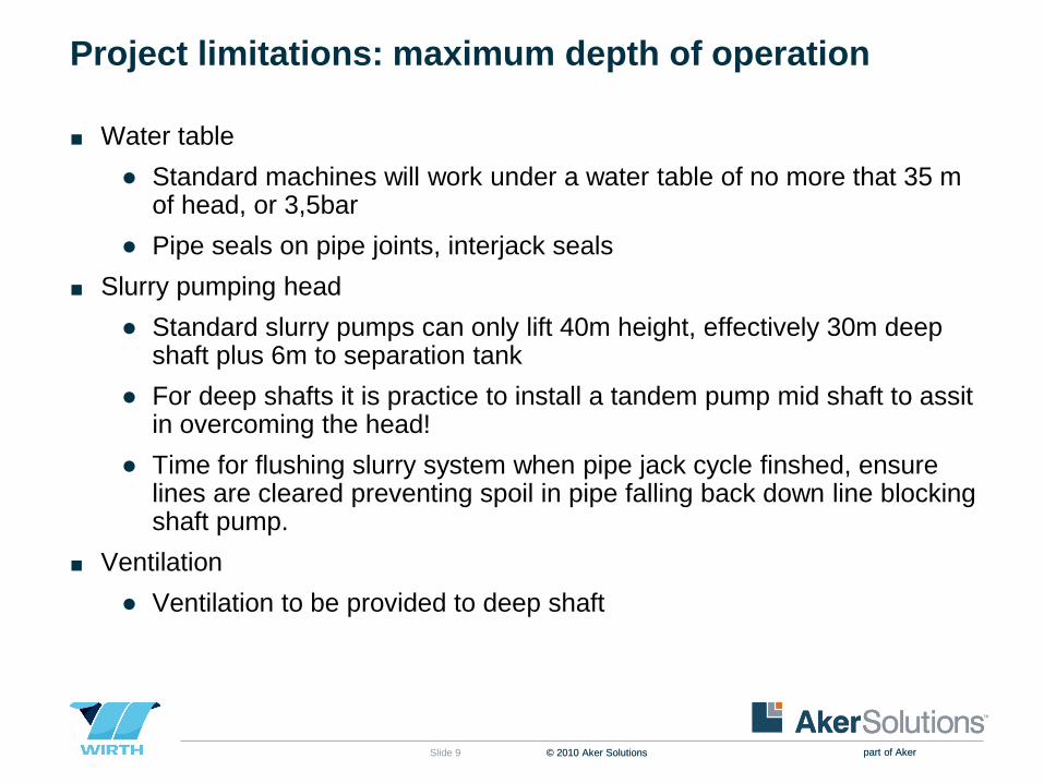
Project limitations: maximum depth of operation
■ Water table
● Standard machines will work under a water table of no more that 35 m of head, or 3,5bar
● Pipe seals on pipe joints, interjack seals
■ Slurry pumping head
● Standard slurry pumps can only lift 40m height, effectively 30m deep shaft plus 6m to separation tank
● For deep shafts it is practice to install a tandem pump mid shaft to assit in overcoming the head!
● Time for flushing slurry system when pipe jack cycle finshed, ensure lines are cleared preventing spoil in pipe falling back down line blocking shaft pump.
■ Ventilation
● Ventilation to be provided to deep shaft

© 2010 Aker Solutions part of Aker © 2010 Aker Solutions part of Aker Slide 10
Project limitations: minimum clearances?
■ Minimum pipe depth below street level
● 1,5 – 2 pipe diameters below street level

© 2010 Aker Solutions part of Aker © 2010 Aker Solutions part of Aker Slide 11
Information transfer: client to manufacturer
■ Soils information with soil reports and bore logs
■ Depth of water over the intended axis for tunnel
■ Shaft depth
■ Total length of project
■ Longest distance between shafts
■ Pipe material and dimensions, length, ID, OD
■ Straight or curved alignments required
■ Delivery time on site
■ Execution time for project
■ Experience level of client

© 2010 Aker Solutions part of Aker © 2010 Aker Solutions part of Aker Slide 12
Information transfer: manufacturer to client
Microtunneling system must have, be capable of the following:
■ Data recording with direct printing or electronic copy of drive record for:
● Steering position
● Laser position on target a
● Length driven, day date time
● Torque cutter head and jacking force
■ Working under water depth of maximum 3,5 bar
■ Offer minimum 3 IJS stations controls
■ Bearing lubrication system
■ Automatic bentonite lubrication system
■ Capacity of working in maximum MPa UCS material
■ Straight or curved alignments required

© 2010 Aker Solutions part of Aker © 2010 Aker Solutions part of Aker Slide 13
Project considerations: urban situation
Jacking shaft
Receiving shaft
Alignment
D=1200m
D=1500m
D=1500m
D=2000m
D=1200m

© 2010 Aker Solutions part of Aker © 2010 Aker Solutions part of Aker Slide 14
Project considerations: soil interfaces

© 2010 Aker Solutions part of Aker © 2010 Aker Solutions part of Aker Slide 15
Project considerations: soil interfaces

© 2010 Aker Solutions part of Aker © 2010 Aker Solutions part of Aker Slide 16
Project considerations: buried services – investigations
■ Check for buried services
■ Bore holes
■ Permissions from utility companies
■ Know what is there!

© 2010 Aker Solutions part of Aker © 2010 Aker Solutions part of Aker Slide 17
Recap on today’s discussion
■ Microtunneling
● Advantages of microtunneling
● Utilities installation by microtunneling
■ Project limitations
● Distance between shafts
● Maximum depth of operation
■ Information transfer
● Information needed from the client
● Information available to the client
■ Project considerations
● Choosing the correct alignment – urban situation
● Choosing the correct alignment – soil interfaces
● Obstructions in the path of the machines
● Buried services – investigations
● Maximum soil strengths

© 2010 Aker Solutions part of Aker © 2010 Aker Solutions part of Aker Slide 18
Thank you for
your kind attention!
Merry Christmas and a safe journey home to
your families
© 2010 Aker Solutions part of Aker © 2010 Aker Solutions part of Aker Slide 19
Copyright
■ Copyright of all published material including photographs, drawings and images in this document remains vested in Aker Solutions and third party contributors as appropriate. Accordingly, neither the whole nor any part of this document shall be reproduced in any form nor used in any manner without express prior permission and applicable acknowledgements. No trademark, copyright or other notice shall be altered or removed from any reproduction.

© 2010 Aker Solutions part of Aker © 2010 Aker Solutions part of Aker Slide 20
Disclaimer
■ This Presentation includes and is based, inter alia, on forward-looking information and statements that are subject to risks and uncertainties that could cause actual results to differ. These statements and this Presentation are based on current expectations, estimates and projections about global economic conditions, the economic conditions of the regions and industries that are major markets for Aker Solutions ASA and Aker Solutions ASA’s (including subsidiaries and affiliates) lines of business. These expectations, estimates and projections are generally identifiable by statements containing words such as “expects”, “believes”, “estimates” or similar expressions. Important factors that could cause actual results to differ materially from those expectations include, among others, economic and market conditions in the geographic areas and industries that are or will be major markets for Aker Solutions’ businesses, oil prices, market acceptance of new products and services, changes in governmental regulations, interest rates, fluctuations in currency exchange rates and such other factors as may be discussed from time to time in the Presentation. Although Aker Solutions ASA believes that its expectations and the Presentation are based upon reasonable assumptions, it can give no assurance that those expectations will be achieved or that the actual results will be as set out in the Presentation. Aker Solutions ASA is making no representation or warranty, expressed or implied, as to the accuracy, reliability or completeness of the Presentation, and neither Aker Solutions ASA nor any of its directors, officers or employees will have any liability to you or any other persons resulting from your use.
■ Aker Solutions consists of many legally independent entities, constituting their own separate identities. Aker Solutions is used as the common brand or trade mark for most of these entities. In this presentation we may sometimes use “Aker Solutions”, “we” or “us” when we refer to Aker Solutions companies in general or where no useful purpose is served by identifying any particular Aker Solutions company.