nonpremixed and premixed flamelets les of partially title ... · 228 y. hu, r. kurose / combustion...
TRANSCRIPT

TitleNonpremixed and premixed flamelets LES of partiallypremixed spray flames using a two-phase transport equation ofprogress variable
Author(s) Hu, Yong; Kurose, Ryoichi
Citation Combustion and Flame (2018), 188: 227-242
Issue Date 2018-02
URL http://hdl.handle.net/2433/230559
Right
© 2017 The Author(s). Published by Elsevier Inc. on behalf ofThe Combustion Institute. This is an open access article underthe CC BY-NC-ND license.(http://creativecommons.org/licenses/by-nc-nd/4.0/)
Type Journal Article
Textversion publisher
Kyoto University

Combustion and Flame 188 (2018) 227–242
Contents lists available at ScienceDirect
Combustion and Flame
journal homepage: www.elsevier.com/locate/combustflame
Nonpremixed and premixed flamelets LES of partially premixed spray
flames using a two-phase transport equation of progress variable
Yong Hu
∗, Ryoichi Kurose
Department of Mechanical Engineering and Science, Kyoto University, Kyoto daigaku-Katsura, Nishikyo-ku, Kyoto 615–8540, Japan
a r t i c l e i n f o
Article history:
Received 1 June 2017
Revised 24 July 2017
Accepted 3 October 2017
Available online 5 November 2017
Keywords:
Mixed reaction regime
Large eddy simulation
Flamelet
Spray effect
Reaction progress variable
a b s t r a c t
Partially premixed spray flames are simulated with flamelet-based tabulated chemistry parameterized by
the mixture fraction and progress variable. The transport equation of the reaction progress variable C is
reconsidered, and its formulation for the reacting two-phase flows is derived and employed, which allows
the inclusion of spray impacts through a new spray source term that is absent in its gaseous form. Both
the nonpremixed and premixed flamelets assuming single reaction regime are implemented in LES, and
their validities in spray flames and dependence on the evaporation effect when considering two-phase
C equation are examined. The effect of spray, reaction and turbulence interaction is then investigated in
comparison with experiments of Sydney reacting acetone sprays, covering the rich, lean and stoichio-
metric cases. The computed results generally follow the experimental data, but a disagreement between
two flamelet simulations is observed especially in rich and lean flames. The premixed flamelets tend
to capture the downstream jet spreading while overestimating the peak temperature compared to the
nonpremixed chemistry. Flame index analysis indicates that in the present spray flames an evaporation-
dominated regime exists inside the upstream core jet and it promotes the coexistence of subsequent
interacting premixed and nonpremixed reaction zones, which impedes accurate flame prediction by the
single regime flamelets. Furthermore, the spray source term appearing in the derived C equation is iden-
tified to act as scalar fluxes driven by sprays in flamelet structures. Including this new source term is
found to be important to account for the dissipation effect induced by evaporation on the reaction zone
in the flamelet simulation of turbulent spray flames.
© 2017 The Author(s). Published by Elsevier Inc. on behalf of The Combustion Institute.
This is an open access article under the CC BY-NC-ND license.
( http://creativecommons.org/licenses/by-nc-nd/4.0/ )
1. Introduction
The use of liquid fuel in turbulent combustion is prevalent
in many industrial devices. The process in those systems in-
volves complex multi-physics and features interactions among
spray evaporation, turbulent transport and vapor fuel/air mix-
ing, as well as chemical reactions that determine the behavior of
such combustion devices in relation to both stability and pollu-
tant emissions. Because of the prevaporization effects and disper-
sion of local fuel droplets, spray flames are often characterized by
a partially premixed reaction mode [1,2] , exhibiting the proper-
ties of both premixed and nonpremixed flames, and show addi-
tional evaporation-dependent flame structures compared to pure
gas combustion [1,3,4] . Consequently, the increased complexities in
∗ Corresponding author.
E-mail address: [email protected] (Y. Hu).
reacting sprays make it challenging for simulation, and selecting or
developing proper numerical tools for spray combustion modeling
is an important issue when the design of more efficient and clean
combustion systems is desired.
Large-eddy simulation (LES) has gained increasing attention in
recent years and proved its ability to yield reliable computations
of complex reacting spray flows [5–10] . Unsteady turbulent struc-
tures and mixing are explicitly resolved in LES, but the modeling of
subgrid scale (SGS) chemical reactions remains a major issue since
the combustion process occurs predominantly in a small scale well
below the LES filter width [11] . Several different LES combustion
models have been successfully applied in previous spray studies,
which are based on either assumed PDF approaches, such as con-
ditional momentum closure [5] and the flamelet approach [6,7] , or
PDF-like models [12] , such as the linear-eddy model [8] and the
transported PDF method [9,10] . Among these combustion models,
the flamelet-based tabulated chemistry approach shows the most
attractive in that with a dramatically reduced computational cost
https://doi.org/10.1016/j.combustflame.2017.10.004
0010-2180/© 2017 The Author(s). Published by Elsevier Inc. on behalf of The Combustion Institute. This is an open access article under the CC BY-NC-ND license.
( http://creativecommons.org/licenses/by-nc-nd/4.0/ )
228 Y. Hu, R. Kurose / Combustion and Flame 188 (2018) 227–242
the detailed chemistry can be incorporated in the modeling, which
is important to accurately describe the emission formation and
transient phenomena highly influenced by the finite-rate chemistry
and spray evaporation [13] .
For the proper calculations of two-phase flows when using
flamelet models, a special care should be paid to the modeling and
inclusion of inter-phase couplings [24] . In both nonpremixed and
premixed gaseous flamelets modeling, the generated flamelets are
usually characterized using two control parameters, the mixture
fraction and the reaction progress variable, where the former de-
scribes the mixedness of fuel and air, and the latter represents the
progress of local reaction. This parameterization of flamelet struc-
tures showed its most robust capability in predicting the various
flame features [25,26] . In the implementation of flamelet models
for turbulent flame simulation, the transport equations of these
two control variables are solved together with other flow variables
and turbulent effects on the chemistry are accounted for in this
manner. The effects, such as the evaporation in spray flames can
usually be included in additional source terms of their transport
equations. Many studies have been devoted to the examination of
the evaporation influence on the mixture fraction field [6,27,28] ,
but few studies have focused on the reaction progress and the
spray effects on reaction progress of local mixtures in reacting
spray flows.
On the other hand, when applied to the spray flames with
mixed interacting combustion regimes, the predictive capabilities
of classical flamelet models need to be reconsidered. A turbulent
flame in flamelet concept is considered as an ensemble of lami-
nar flames (i.e., the so-called flamelets) [14] and two main strate-
gies to generate the flamelet structures can be found in the lit-
erature, which rely on either nonpremixed or premixed flames
[15–17] . These two types of flamelet formulations are, therefore,
arguably apropos to the description of flames only in the sin-
gle nonpremixed or premixed burning regime. Recently Knudsen
and Pitsch [18] attempted to combine nonpremixed and premixed
flamelets in one simulation of an LES spray combustor, where a
combustion regime index was used to differentiate the local pre-
mixed and diffusion modes of burning. However, this index in its
own form presents more complexity and neglects the subfilter con-
tributions where evaporation is significant. Thus, because of the
lack of a more reliable flamelet model for spray flames, the clas-
sical single flamelet model is still used broadly in studies on react-
ing spray simulations [6,7,19,20] . EI-Asrag et al. [19] used a non-
premixed flamelet (i.e., the flamelet-progress variable approach) in
the large eddy simulation of a lean direct injector combustor to
study the emission characteristics. The same flamelet model was
adopted by Tachibana et al. [20] in an investigation of combus-
tion instability of a model aircraft combustor. Among recent LES
studies, the premixed flamelets were reported in the simulation
of the Sydney piloted spray flames [6] . These studies showed that
the single flamelet models can somehow reproduce some features
of spray flames, but questions still remain regarding to which ex-
tent the different single flamelet models can describe the flames
at the partially premixed operating conditions and how this would
affect the couplings with spray dynamics. Though the performance
of different flamelet-based tabulation approaches has been inves-
tigated in a few studies of gaseous flames [21,22] , it has not been
completely identified in the context of spray combustion. Partic-
ularly, spray flames feature more complex local flame structures
with more distributed and coupled multi-reaction regimes com-
pared to the gaseous counterpart [23] .
The main objective of the present work is to identify the spray
effects on the reaction progress in the flamelet-based LES mod-
eling and thus, the transport equation of reaction progress vari-
able is reconsidered, and its formulation for two-phase flames
is derived. To understand the capabilities and limitations of
single-regime flamelets with respect to the prediction of spray
flames and their performance with spray impacts when integrating
this two-phase transport equation of progress variable, both the
nonpremixed and premixed flamelets LES simulations are applied
to experimental Sydney partially premixed spray flames with cases
featuring various inlet equivalence ratio [29] . The remainder of this
paper is organized as follows. The governing equations for gas and
liquid phases are introduced in the next section. The emphasis is
on the discussion of the derived equation for the progress variable
and the closure method for the unclosed terms. Section 3 gives
the experimental setup and computational details. The main re-
sults and discussion are presented in Section 4 , which is followed
by the conclusion section.
2. Methodology
2.1. LES governing equations
In the LES of reactive two-phase flows, based on the dilute ap-
proximation the filtered conservation equations of gas-phase mass,
momentum, and energy, neglecting the volume displacement of
dispersed phase, are solved and they are given as
∂ ρ̄
∂ t +
∂( ̄ρ ˜ u i )
∂x i =
˙ S v , (1)
∂( ̄ρ ˜ u j )
∂ t +
∂( ̄ρ ˜ u i ̃ u j )
∂x i = − ∂ p̄
∂x j +
∂
∂x i
[ 2 ̃ μ
(˜ S i j −
1
3
δi j ̃ S kk
)] −
∂ ̄τ sgs i j
∂x i +
˙ S m , j , (2)
∂( ̄ρ ˜ h )
∂ t +
∂( ̄ρ ˜ u i ̃ h )
∂x i =
∂
∂x i
(ρ̄ ˜ αh
∂ ̃ h
∂x i
)− ∂ J sgs
h
∂x i +
˙ S e . (3)
In the above equations, the resolved density-weighted filtered vari-
able is f̄ = ρ f / ̄ρ, and the overbar represents the spatial filtering.
ρ̄ is the gas density, ˜ u i the velocity, p̄ the pressure, ˜ S i j the rate-of-
strain tensor given by
˜ S i j =
1
2
(∂ ̃ u i
∂x j +
∂ ̃ u j
∂x i
), (4)
and the subgrid, unsolved stress τ̄ sgs i j
= ρ̄ ˜ u i u j − ρ̄ ˜ u i ̃ u j ; based on an
eddy viscosity assumption, the Smagorinsky model is used to ap-
proximate the deviatoric part of this term at the scale of cell width
� as τ̄ sgs i j
= −2 μt ̃ S i j with μt = ρ̄(C s �) 2 (2 ̃ S i j ̃ S i j )
1 / 2 . Here, the model
coefficient C s is obtained using a dynamic procedure [30] . ˙ S v , ˙ S m , j
and
˙ S e are the source terms for mass, momentum and energy, re-
spectively, accounting for the exchanges between the gas and liq-
uid phases. ˜ h is the total enthalpy, and it is included here in or-
der to evaluate the gas-phase temperature that accounts for the
spray effect using the correction �T = ( ̃ h − h c ) /C p [1] . As empha-
sized by Baba and Kurose [1] , the heat loss due to droplet evap-
oration is relevant in spray flames. The enthalpy h c taken from
flamelet libraries does not include the evaporation effect and a
temperature modification should be applied when the enthalpy
solved in flowfield outstrips the lower limits of that in flamelet
table. The gaseous temperature obtained in this way is also used
in the droplet evolution equations. h c and heat capacity C p are the
tabulated values in the flamelet database introduced below.
In reacting flows, the evolution of reactants and products in-
volved in the chemical reactions are also relevant, and it involves
the formation and transportation of thousands of species depend-
ing on the fuel considered [12] . A direct solution of the transport
Y. Hu, R. Kurose / Combustion and Flame 188 (2018) 227–242 229
equations for all species is usually not viable in practical 3D com-
bustion simulations. Alternatively, a reduced set of control vari-
ables are adopted in a flamelet model to parameterize and tabulate
the detailed chemistry database. Usually the mixture fraction Z and
progress variable C are selected and their transport equations are
solved in conjunction with the flow field. In two-phase flows, the
Favre-filtered equation for the mixture fraction can be expressed
as,
∂( ̄ρ ˜ Z )
∂ t +
∂( ̄ρ ˜ u i ̃ Z )
∂x i =
∂
∂x i
(ρ̄ ˜ αZ
∂ ̃ Z
∂x i
)− ∂ J sgs
Z
∂x i +
˙ S v , (5)
where the effects of spray evaporation are added in the source
term
˙ S v .
The reaction progress variable includes the information of the
extent of reaction progress of the reactant mixture. Often, the re-
acting mixture is described in terms of the mass fraction of major
species, the linear combination of which is usually used to define
the progress variable [15,16,25] . In this work, according to [31,32] ,
the following formulation of progress variable in a normalized
form is chosen
C =
Y c
Y eq c
, (6)
where Y c is the sum of CO 2 , CO, H 2 O and H 2 mass fractions
Y c = Y CO 2 + Y CO + Y H 2 O + Y H 2 , (7)
which is consistent with previous studies on hydrocarbon
flames [15] , and Y eq c is the chemical equilibrium value of Y c in the
reactant mixture, which depends on the mixture fraction Z . The
progress variable C defined by Eq. (6) is in the range of [0, 1],
where C = 0 corresponds to the unburnt mixture and C = 1 the
burnt mixture, and it serves as a useful marker for the descrip-
tion of reaction zone transition in partially premixed combus-
tion [32,33] . Its balance equation for spray flows, as derived in Ap-
pendix A, is given as
∂( ̄ρ ˜ C )
∂ t +
∂( ̄ρ ˜ u i ̃ C )
∂x i =
∂
∂x i
(ρ̄ ˜ αC
∂ ̃ C
∂x i
)− ∂ J sgs
C
∂x i +
¯̇̄ ω c +
˙ S c , (8)
¯̇̄ ω c =
¯̇ ω c + C
1
Y eq c
d 2 Y eq c
dZ 2 ρχZ ︸ ︷︷ ︸
ω (I)
+ 2
1
Y eq c
dY eq c
dZ ρχZ,C ︸ ︷︷ ︸
ω ( II )
, (9)
˙ S c = −C 1
Y eq c
dY eq c
dZ ( ̇ S v − Z ̇ S v ) , (10)
where at the right hand side of Eq. (8 ), in addition to the diffu-
sion term and chemical reaction term
¯̇̄ ω c that will be encountered
in the C equation for gas flames, the last term
˙ S c is new, and it
represents the source term that stems from spray evaporation. The
closed forms of these two sources are discussed in the next sec-
tion. Here, J sgs
= ρ̄ ˜ u i − ρ̄ ˜ u i ̃ ( = [ h, Z, C] ) is the residual subgrid
scalar flux, and it is modeled as
J sgs
= −ρ̄αt, ∂ ˜
∂x i , (11)
where the turbulent eddy diffusivity αt , is determined by αt, =
μt / (ρSc t ) with Sc t = 0 . 4 [34] . It is important to note that in ad-
dition to the new spray source term appearing in Eq. (8) , the un-
closed reaction rate includes two more terms ω (I) and ω (II) that
are associated with the scalar dissipation terms of χ Z and χ Z,C ,
which are absent in the fully premixed combustion and represent
the contributions from the diffusion mode of burning. Their im-
portance in a liquid-fueled partially premixed case remains to be
discussed.
2.2. Closure of reaction rate
The filtered chemical reaction rate in the transport equation of
progress variable is obtained by the convolution of the tabulated
chemistry database with the probability density function (PDF) to
account for the sub-grid turbulent fluctuation effects, which is ex-
pressed as
¯̇ ω c =
∫ 1
0
∫ 1
0
˙ ω c (Z, C) ̃ P (Z, C) dZdC, (12)
and
ω (I) =
˜ C ρ̄ ˜ χZ
∫ 1
0
1
Y eq c (Z)
d 2 Y eq c (Z)
dZ 2 ˜ P (Z) dZ, (13)
ω ( II ) = 2 ̄ρ ˜ χZ,C
∫ 1
0
1
Y eq c (Z)
dY eq c (Z)
dZ ˜ P (Z) dZ. (14)
Here, ˙ ω c (Z, C) is the chemical reaction rate which is read in the
flamelet database. ˜ P (Z, C) is the joint filtered density function de-
scribing the subfilter distribution of the control variables Z and C .
The equilibrium value of Y eq c (Z) is a function of mixture fraction,
and it is evaluated in the flamelet tabulation procedure.
The scalar dissipation ρ̄ ˜ χZ = ρα|∇Z| 2 , decomposed into the re-
solved and subfilter part χ sgs Z
, is determined in the following man-
ner [35]
ρ̄ ˜ χZ = ρ̄α|∇ ̃
Z | 2 + χ sgs Z
, (15)
with
χ sgs Z
= βZ ρ̄αt
�2 ̃ Z ′′ 2 , (16)
where ˜ Z ′′ 2 is the variance of mixture fraction and βZ a model con-
stant.
ρ ˜ χZ,C = ρα∇ Z · ∇ C in Eq. (14) corresponds to the cross-scalar
dissipation rate of the mixture fraction Z and progress variable C ,
and it describes the transport of the reactant mixture across the
iso-surface of Z . This term is modeled by the square root of the
product of scalar dissipation rates for the mixture fraction ˜ χZ and
progress variable ˜ χC , as [32,36]
˜ χZ,C =
√
˜ χZ × ˜ χC , (17)
where ˜ χC is approximated by a commonly used model akin to the
formulation of ˜ χZ as [37]
ρ̄ ˜ χC = ρ̄α|∇ ̃
C | 2 + χ sgs C
and χ sgs C
= βC ρ̄αt
�2 ̃ C ′′ 2 . (18)
In Eqs. (16) and (18) , the model coefficients βB and βC are the time
scale ratios and assigned with the value 1.0 [37] in the present
study.
2.3. Flamelet modeling
Both nonpremixed and premixed tabulation techniques are used
in this work to generate flamelet databases for the prescription
of reaction rate described in the above section. The nonpremixed
flamelet model assumes the 1D diffusion flame as the basic chem-
ical structure composing the turbulent flames, where the chemical
source term is deemed to be mainly balanced by the diffusion pro-
cesses [14]
−ρχZ ∂ 2 Y i ∂Z 2
= ˙ ω Y i . (19)
On the other hand, the premixed flamelet structures are obtained
by the solution of a laminar steady premixed flame [17]
ρu S l,u ∂Y i ∂x
=
∂(ρV i,x Y i )
∂x + ˙ ω Y i . (20)

230 Y. Hu, R. Kurose / Combustion and Flame 188 (2018) 227–242
Here, Y i is the species mass fraction and ˙ ω Y i the corresponding
chemical reaction rate. ρu and S l, u are the unburnt mixture density
and the laminar flame speed, respectively. V i, x denotes the mass
diffusion velocity of species i .
In terms of Eq. (19) , the diffusion flamelets are calculated with
the scalar dissipation rate χ Z ranging from a very small value to
the extinction value, the solution of which would correspond to
an S-curve [15] . The steady flamelet structures together with the
unstable flamelet solutions along this curve are then tabulated in
a table lookup parameterized by the mixture fraction and progress
variable. On the other hand, the premixed flamelet table consists
of premixed flame structures generated by means of Eq. (20) with
various initial fuel/air mixing states.
For application to the LES simulation, the generated flamelet
databases need to be formulated to the Favre-filtered quantities
by integrating the joint PDF ˜ P (Z, C) . In the widely used presumed
PDF modeling [6,7,12] , under the assumption of statistical inde-
pendence, the joint PDF is often expressed as the product of the
marginal PDF of the dependent variables, ˜ P (Z, C) =
˜ P (Z) ̃ P (C) .
In this study, the presumed PDF method is adopted with a beta-
PDF distribution for Z and a delta function for C in nonpremixed
flamelet modeling as
˜ ψ =
∫ 1
0
ψ ̃
P (Z ; ˜ Z , ̃ Z ′′ 2 , ˜ C
)dZ, (21)
and with a beta PDF describing the distribution of C and delta
function for the Z in premixed flamelet modeling
˜ ψ =
∫ 1
0
ψ ̃
P (C ; ˜ C , ̃ C ′′ 2 , ̃ Z
)dC, (22)
where ψ denotes the reaction rate and species mass fraction that
are obtained from the flamelet tables. ˜ Z ′′ 2 and
˜ C ′′ 2 are the fil-
tered variance of mixture fraction and progress variable, respec-
tively, and used in the evaluation of the beta PDF distribution. They
are determined in the LES calculation by their algebraic model
˜ ′′ 2 = βv �2
(∂ ˜
∂x i
)2
(23)
with the model constant βv set to 0.15 according to [6,39,40]
It is worth mentioning that the combination of flamelet mod-
els with the transported PDF method is another reliable alternative
approach in spray combustion simulations [26,41] that avoids the
statistical independence assumption for the joint PDF and directly
solves the transport equation of joint PDF of the mixture fraction
and other considered control variables, although additional com-
putational cost may arise due to the solution of high-dimensional
PDF transport equation. This approach is outside the scope of this
study, and the reader can refer to Ref. [42] for more information.
2.4. Sub-models for liquid phase
The liquid phase is assumed to be dilute spray consisting of
spherical single-component droplets. The droplet coalescence or
breakup is not considered. The dilute spray evolves according to
a set of Lagrangian equations describing the dynamics of fuel
droplets including their temperature, T d , mass, m d , velocity, v d , and
trajectory, x d , in the continuous gas phase. With the assumption of
heavy particles, the forces considered to have a significant contri-
bution to the droplets motion include the drag force, gravitational
force and a random force due to the subgrid fluctuations in LES
d x d = v d dt, (24)
d v d =
(˜ u − v d
τd
)d t + g d t +
(C 0 k
sgs
τc
)1 / 2
d W , (25)
d T d =
Nu
3 P r
(c p,g
c p,l
)f 2 (
˜ T − T d )
τ St d
d t +
L V c p,l
(d m d
m d
), (26)
dm d = −m d
τ St d
(Sh
3 Sc
)ln (1 + B M
) dt. (27)
Here, ˜ u , and
˜ T are the local gas properties, namely gas velocity and
temperature, respectively, at the droplet position. L V is the latent
heat of evaporation, g the gravitational acceleration, c p, g and c p, l
the specific heat capacities of the gas and liquid phase, Nu and Sh
the Nusselt number and Sherwood number. τ St d
= 2 ρl r 2 d / (9 μ) the
particle relaxation time in Stokes regime. f 2 is the correction fac-
tor for the interphase thermal transfer of evaporating droplets [43] .
k sgs = C − 8
3 s ( μt
ρ̄� ) 2 is the subgrid kinetic energy and C 0 = 1 [44] . dW
denotes the increment of a stochastic Wiener process. τ d is the
particle kinetic response time and can be expressed as
τd =
8
3
ρl
ρg
r d C D | ̃ u − v d | , (28)
where r d is the particle radius, ρg the gas density, ρ l the density
of droplets and C D the drag coefficient given by an empirical ex-
pression [1]
C D =
24
Re d
[ 1 + 0 . 0545 Re d + 0 . 1 Re 0 . 5 d ( 1 − 0 . 03 Re d )
1 + b| Re b | c ] , (29)
b = 0 . 06 + 0 . 077 e (−0 . 4 Re d )
c = 0 . 4 + 0 . 77 e (−0 . 04 Re d ) (30)
in which Re d = 2 ρg r d u sl /μ and Re b denote the droplet Reynolds
numbers based on the slip velocity u sl = | ̃ u − v d | and the blowing
velocity u b =
dm d dt
(4 π r 2 d ρg ) −1 , respectively.
According to [44] , τ c denotes a typical timescale for the interac-
tions between the particle and turbulence, and it is evaluated with
τc = τ 2 a d
(�√
k sgs
)1 −2 a
, and a = 0 . 8 . (31)
The mass transfer number B M
is the normalized fuel flux
around the droplet surface, which involves the fuel mass fraction
in surrounding gas ˜ Y F and that at the droplet surface Y F, s
B M
=
Y F,s − ˜ Y F 1 − Y F,s
(32)
with Y F, s determined by the Clausius–Clapeyron relation [1,45] .
Additionally, studies have shown the important effects of SGS
scalar fluctuations in the modeling of spray properties, includ-
ing auto-ignition [46] . In this study, we adopt a technique in the
framework of flamelet modeling that uses the subfilter presumed
PDF to prescribe random gas quantities of ˜ Y F and
˜ T for the evap-
orating droplets [28] . In this algorithm, the pairing procedure of
the droplets with a stochastic value of ˜ Y F or ˜ T is reinitiated after
an intermittent coupling process, which was set based on the SGS
turbulence timescale, τt =
�2
max (α,αt ) , as applied in the study of De
and Kim [28] . In this work, a time of min (τt , τc ) is used instead
to ensure the droplet/gas subfilter correlation is renewed when the
droplet breaks away from an eddy or the eddy is dissipated, and to
numerically avoid the appearance of spurious long-duration corre-
lation.
2.5. Spray source terms
The spray source terms in the gas-phase governing equations
account for the two-phase coupling through heat and mass trans-
fers. By using the particle-source-in-cell (PSI-Cell) method [1] , the

Y. Hu, R. Kurose / Combustion and Flame 188 (2018) 227–242 231
mass, momentum, and energy exchange terms, which are ˙ S v , ˙ S m
,
and
˙ S e , respectively, in Eqs. (1) –(3) are expressed as
˙ S v = − 1
�V
N d ∑
k =1
n d ,k
d
dt
(m d ,k
)(33)
˙ S m
= − 1
�V
N d ∑
k =1
n d ,k
d
dt
(m d ,k v d ,k
)(34)
˙ S e = − 1
�V
N d ∑
k =1
n d ,k
[ 1
2
d
dt
(m d ,k v
2 d ,k
)+
d
dt
(m d ,k c p,l T d ,k
)] (35)
where the spray source terms in each cell volume �V are obtained
from the summation of all the droplet parcels located within this
cell. Droplet groupings are used, and n d, k represents the number
of real fuel droplets in one computational parcel k .
The source term
˙ S c appearing in the newly derived C equation
(8) can be obtained with
˙ S c = − ˜ C
(˙ S v − ˜ Z ̇ S v
)∫ 1
0
1
Y eq c (Z)
dY eq c (Z)
dZ ˜ P (Z) dZ, (36)
neglecting the higher-order correlations in the spray source, mix-
ture fraction and progress variable field.
3. Flame configuration and computation details
3.1. Test cases
The flames considered in the present LES computations are the
piloted turbulent spray flames, which were experimentally stud-
ied at the University of Sydney [29] . This Sydney piloted spray
burner bears an open annular configuration and is well designed to
be representative of reactive spray flows stabilized by hot gaseous
mixtures that are widely encountered in real engine applications.
The burner geometry comprises a central spray jet along with a
mixture of prevaporized fuel and air, surrounding which is an an-
nulus of outer diameter 25 mm supplying the hot-pilot stream for
the stabilization of the main jet. A stoichiometric mixture of acety-
lene, hydrogen and air is maintained for the pilot flow. The spray is
generated by an ultrasonic nebulizer placed 215 mm upstream of
the jet exit plane, and the central nozzle diameter D = 10 . 5 mm.
Moreover, there is an air co-flow with a diameter of 104 mm and
bulk velocity of 4.5 m/s. A series of cases involving nonreacting
and reacting sprays with acetone and ethanol fuel droplets have
been investigated with this burner, of which three with acetone
fuel are simulated in this work. They are referred to as AcF3, AcF4
and AcF6, which feature the rich, lean and stoichiometric operating
condition, respectively.
3.2. Computational methods and boundary conditions
A sketch of the computational domain is presented in Fig. 1 .
The simulations are performed using an in-house LES code
FK
3 [1,47,48] with the finite difference formulation in a Carte-
sian coordinate system. The spatial gradients in the momentum
equation are approximated with a fourth-order central difference
scheme, and a WENO scheme is used for the discretization of non-
linear terms in the scalars’ governing equations. The time integra-
tion is based on a third-order explicit Runge–Kutta method. The
computational domain extends to 48 D × 11 D × 11 D in three direc-
tions and consists of around 5 M grid points with finer meshes
near the inlet and shear layer. The diffusion and premixed flamelet
libraries for acetone/air combustion are generated using the config-
urations of a 1D counterflow diffusion flame and a premixed freely
propagating flame, respectively, with the FlameMaster code [38] .
Fig. 1. Sketch of the computational domain. .
In flamelet equations, the boundary conditions at Z = 1 and Z = 0
are set as pure fuel acetone and air at temperature of 300 K. A
detailed reaction mechanism with 83 species and 419 element re-
actions, developed by Pichon et al. [49] is used to model the ace-
tone oxidation. The stoichiometric mixture fraction Z st is 0.095.
The diffusion flamelet solutions comprise the solutions with the
scalar dissipation rate varying from 0.1 ×10 −2 /s to the extinction
value of 102/s, resulting in a total of 126 different steady and un-
steady flamelet solutions. The flammable region in the premixed
acetone flame calculation is in the equivalence ratio range of (0.39,
2.55), and a linearly interpolated mixing state is applied outside
this flammability limit. It is noteworthy that in case of occurrence
of envelope flame, where chemical reaction can happen around
each droplets, this mixing assumption might be violated for the
mixture at the lean side [50] due to the increased temperature and
species gradient in the gas area around this envelope flame. But in
both the experimental and computational studies of present dilute
spray flames [28,29] , there is no clear indication of the existence
of envelope flame, which is thus assumed to be negligible and not
considered in the present study.
The boundary data of the gas phase and liquid phase at the first
experimental cross-section are used to determine the inlet com-
putational profiles. A digital filter technique is employed to gener-
ate the pseudo-turbulence for the jet velocities at inlet based on
the method proposed by Klein et al. [51] . The progress variable in
the pilot-stream is set to unity and zero for other inlet bound-
aries. The inlet liquid particles are randomly distributed around
each grid point, and the droplet size is assigned with the Rosin–
Rammler distribution, matching the measured Sauter mean diam-
eter. The droplet grouping is used depending on the size, and for
each size group, particle velocity is assigned based on the veloc-
ity distribution of specific size class given by experiments. The
number of droplets within each parcel is determined such that
the measured liquid fuel mass flow rate is preserved. The number
of droplet parcels in the computational domain remains around
6.5 × 10 5 , and a few cases with higher and lower particle numbers
have been studied to ensure the suitability of the particle number
used in the present computations. The statistics are collected for
each case over eight flow-through times, and all simulations are
performed using CRAY: XE6 at the ACCMS, Kyoto University with
576 cores and approximately 100 h of wall clock time.

232 Y. Hu, R. Kurose / Combustion and Flame 188 (2018) 227–242
Table 1
Experimental inlet conditions of acetone fuel spray flames,
AcF3, AcF4 and AcF6, experimental set B [29] .
Test Case AcF3 AcF4 AcF6
Bulk jet velocity (m/s) 24 24 36
Hot-pilot stream velocity (m/s) 11.4 11.4 11.4
Bulk co-flow velocity (m/s) 4.5 4.5 4.5
Air carrier flow-rate (g/min) 150 150 225
Liquid fuel flow-rate (g/min) 19.4 10.4 21.6
Vapor fuel flow-rate (g/min) 25.7 13.0 23.4
Equivalence ratio 1.6 0.8 1.0
The inlet boundary conditions for the three cases of reacting
acetone spray (AcF3, AcF4 and AcF6) are listed in Table 1 .
4. Results
4.1. Spray flames calculated with different flamelet databases
Partially premixed acetone spray flames have been simulated
and the acetone/air combustion is described with the tabulated de-
tailed chemistry by counterflow diffusion flamelet and premixed
flamelet, respectively. The Sydney spray flames characterized by
different rates of pre-vaporization, covering cases of rich (AcF3),
lean (AcF4), and stoichiometric (AcF6) premixing mixtures at inlet,
are considered with an attempt to thoroughly examine the perfor-
mance of different tabulated chemistries and the effects on spray
dynamics.
4.1.1. Gas temperature
Figure 2 shows the snapshots of the instantaneous gas-phase
temperature for spray flames of AcF3, AcF4 and AcF6, where for
each case the figures at the left and right hand side correspond
to the results from the nonpremixed and premixed flamelet cal-
culations, respectively. By comparing three flame cases, it can be
seen that the computed temperature in the premixed and non-
premixed cases differ from each other, especially near the center
part of the jet. The diffusion flamelet (left-side figure for each case)
computes an earlier combustion with the center flame front estab-
lished closer to the nozzle exit, and comparatively, this inner flame
brush is anchored further downstream in the simulations with
premixed flamelets (right-side figure in each case). This is partic-
ularly evident in the rich case of spray flame AcF3. Meanwhile, it
can be observed that this center high-temperature reaction zone
initiates earlier in the lean spray flame AcF4 than in AcF3 or the
stoichiometric case AcF6, which has the most reactive mixture at
the inlet. The reason for this will be discussed in the subsequent
section. Since the injected fuel droplets move towards this inner
flame front, the predicted distinct temperature is expected to af-
fect the spray evaporation, the statistics of which will be discussed
in Section 4.1.2 .
With the general idea obtained from the above comparison,
Fig. 3 compares the experimental measurements with the radial
profiles of mean gas temperature at different axial locations x / D =
10, 20, and 30, computed using nonpremixed and premixed
flamelets for three flame cases. Overall, the trends of changes that
the experimental values suggest towards the downstream of the
jet are captured by two flamelet model computations. In the three
cases, at the jet exit spray flames are characterized by the par-
tially premixed vapor fuel/air mixtures at the ambient tempera-
ture. When injected into the combustion field, this center jet mix-
ture together with fuel droplets is sheathed by the pilot flame, and
due to the high initial momentum of the jet carrier, the immedi-
ate inward propagation of the hot-pilot stream is retarded. How-
ever, when moving downstream away from the nozzle exit, be-
cause of the turbulent mixing and droplet evaporation, the main
jet is slowly heated up, as evidenced by the increasing values of
gas temperature near the centerline indicated by the experiments
and both nonpremixed and premixed computations. In comparison,
a marked difference is found in the predictions by the two flamelet
databases. The nonpremixed flamelet predicts a higher tempera-
ture compared to the premixed flamelet, indicating the important
influence of turbulence/chemistry interactions on the inner flame
propagating. In general, the premixed flamelet shows a better re-
sult in capturing the flame spreading in the radial direction to-
wards the downstream locations.
Additionally, it is observed that, near the flame edge of the ra-
dial position r/D = 1 , where the stoichiometric mixtures are lo-
cated, the premixed flamelet slightly overestimates the peak tem-
perature. As pointed out by Ramaekers et al. [22] in the study
of different flamelet models for the simulations of Sandia flames,
the difference between flamelets in the species mass fraction
Fig. 2. Representative instantaneous filtered gas temperature for spray flame AcF3, AcF4 and AcF6, where the predicted results from nonpremixed and premixed flamelet
models are presented at left and right hand side, respectively, for each case.

Y. Hu, R. Kurose / Combustion and Flame 188 (2018) 227–242 233
Fig. 3. Comparison of radial distribution of mean gas temperature profile predicted by nonpremixed and premixed flamelet database for spray flames AcF3 (left), AcF4 (mid-
dle) and AcF6 (right) at three downstream locations of x / D = 10, 20, and 30. Solid line: nonpremixed flamelet calculations; Short dash: premixed flamelet calculations; Filled
dots: experimental data [29] .
predictions can be attributed to the fact that in the nonpremixed
flamelet, species are transported between the iso-mixture fraction
line passing through the Z st plane where intense reaction occurs,
while they only diffuse in the C -direction in premixed flamelets.
This can be used to explain the overestimated peak of flame tem-
perature in premixed flamelet modeling. The diffusion of heat from
the reaction zone ( Z = Z st ) to the surrounding mixtures is guaran-
teed in diffusion flamelets.
Furthermore, note that, in AcF6, although reasonable agree-
ment with the experimental data is observed for the predictions
at the downstream locations, a considerable underprediction of
gas temperature near the centerline by both the nonpremixed
and premixed simulations is found at the upstream cross-section
x / D = 10. Similar disagreements have been reported in other stud-
ies [5,39,40] . It was argued that this deviation from the experimen-
tal data can arise from the uncertainty in the measurements. In the
experiments, the gas-phase temperature was measured using ther-
mocouples, which can lead to significant errors in the high tem-
perature zone of two-phase flows.
4.1.2. Spray statistics
In this section, the influences of diffusion and premixed
flamelet calculations on the droplet properties, namely evaporation
and dispersion, are studied in comparison with the available exper-
imental data [29] .
In Fig. 4 , the computed radial profiles of droplet Sauter mean
diameter (SMD) at four different cross-sections x / D = 5, 10, 20,
and 30 are compared with experimental data. In the two different
flamelet modelings, the simulated values generally follow the mea-
sured profiles of droplet SMD in all three cases, although an over-
estimated SMD is obtained by both flamelets in the simulations of
spray AcF4 for the cross-sections x / D > 10. These higher values can
be attributed to the overpredicted gas-phase temperature seen in
Fig. 3 for AcF4 at x / D = 10. Similar apparent discrepancies are also
observed in AcF3 at x/D = 30 , where the nonpremixed flamelet
yields a much larger SMD than both the premixed flamelet and
measurements, and this is consistent with the noted disparity in
temperature profiles shown at the same location in Fig. 3 . This
observed concordance between the predicted SMD and tempera-
ture can be due to the poly-dispersity of present spray flames.
A wide range of droplets differing in size and dynamic history
dictate the injected sprays, within which the small droplets tend
to evaporate faster and are more likely affected by the gas tem-
perature. Comparatively, the larger droplets can survive far down-
stream, and more time is needed for heating up the large droplets
because of the size dependence of relaxation time [26] . Also, it is
noted that, when approaching the flame region 0.4 < r / D < 0.8 (the
shear layer between the main jet and pilot flame), the predictions
yield a slightly higher SMD compared to the measured data, which
suggests the droplets on the jet edge evaporate more rapidly than
those in the inner region of the spray.
Figure 5 shows the radial profiles of the axial mean, U d and
fluctuating, U
′′ d
velocities of droplets at four cross sections. Gener-
ally, the computations show good agreement with measurements.
The calculated mean droplet axial velocities from flamelet mod-
els well capture the trend of droplet dispersion when traveling
far away from the jet exit, but a distinguishable disagreement be-
tween the two flamelet predictions is found. This can be related
to the thermal expansion effect induced by heat release in the
main jet. As discussed in Figs. 2 and 3 , different predictions on the
progress of combustion in the core zone of jet have been made
by the nonpremixed and premixed flamelet simulations. Concern-
ing the fluctuating velocity U
′′ d , far from the centerline, the com-
puted values tend to exceed the experimental data. However, the
present LES calculation shows a better agreement than that ob-
tained in the RANS simulation [52] , in which the velocity fluctu-
ations are underpredicted owing to the inadequate estimation of
turbulent intensity. Similar observations on the overestimation of
droplet fluctuating velocity were made in other LES studies [6,39] .
The predicted higher temperature and the enhanced evaporation
associated with it could have caused this discrepancy. The con-
sideration of an adequate dispersion model is also expected to
improve the results since the overprediction can be a result of
insufficient droplets near the flame edge for obtaining the spray
statistics.
4.1.3. Reaction zone
As discussed above, the combustion chemistry described by dif-
fusion and premixed flamelets leads to different flame structures
in terms of the gas temperature and spray evaporation. In this

234 Y. Hu, R. Kurose / Combustion and Flame 188 (2018) 227–242
Fig. 4. Comparison of Sauter mean diameter (SMD) predicted by nonpremixed and premixed flamelet simulations with experimental data for spray flames AcF3 (left),
AcF4 (middle) and AcF6 (right) at four axial locations of x / D = 5, 10, 20, and 30. Solid line: nonpremixed flamelet calculations; Short dash: premixed flamelet calculations;
Dots: experimental data [29] .
Fig. 5. Comparison of droplet mean and fluctuating axial velocity U d , U ′′ d
predicted by nonpremixed and premixed flamelet simulations with experimental data for spray
flames AcF3 (left), AcF4 (middle) and AcF6 (right) at four axial locations of x / D = 5, 10, 20, and 30. Solid and dash-dot lines: nonpremixed flamelet calculations; Short dash
and dot lines: premixed flamelet calculations; Square: measured data of U d ; Circle: measured data of U ′′ d
[29] .
section, the reaction mode is explored to further analyze the key
mechanism.
Figure 6 illustrates the instantaneous field of reaction rate over-
lapped with the isoline of gas temperature T = 738 K in AcF6
predicted by the two flamelet calculations. Firstly, as expected, it
is noted that in the two figures the isoline of T = 738 K, which
is the ignition temperature of the acetone/air mixture, gener-
ally embraces the region in which the main reaction occurs. The
high-temperature reaction zone initiated from the reactive pilot
developed with increasing distance from the exit plane through ei-
ther the coflow entrainment or ignition of central premixed fuel
mixture, which could be delayed or prompted by the evapora-
tion. On the other hand, it is seen that the combustion reaction in
these two flamelet computations shows significantly different pat-
terns. The premixed flamelet computes two evident areas of reac-
tion on either side of the pilot-stream which are mainly attached
to the flow interface between the pilot with main jet and coflow.
In comparison, the nonpremixed flamelet leads to a more widely

Y. Hu, R. Kurose / Combustion and Flame 188 (2018) 227–242 235
Fig. 6. Snapshots of the reaction rate predicted by nonpremixed (left) and premixed
(right) flamelet simulations of spray flame AcF6. Black solid line: isoline of gas tem-
perature with value of 738 K.
distributed reaction. Comparisons are also conducted for two other
test flames (not shown here), where a similar observation is ob-
tained.
Figure 7 shows scatter plots of gas-phase temperature, T against
the equivalence ratio, φ for the three test flames obtained by us-
ing the nonpremixed (top) and premixed (bottom) flamelet. The
samples in the plots are collected from all the filter cells at the
across-section x / D = 10. In general, a closed circle formed by the
scatters is observed in the T − φ map, which substantially differs
from the one that would be observed in the gaseous flames oper-
ated using a similar piloted burner [53] . Comparatively, a cluster of
scatter data exists on the rich-side of the flame ( φ > 1) that varies
with temperature and equivalence ratio, which is created mainly
by spray evaporation in the central jet. Depending on the distance
from the piloted reacting front, fuel droplets show a different de-
gree of evaporation. The fuel pockets left by the evaporation then
mix with the oxidiser and form a core domain of stratified com-
bustible gases characterised by an increasing temperature with the
increase of equivalence ratio. For a given value of equivalence ra-
tio, a number of scatters with a slowly rising reaction rate are ob-
served, corresponding to a premixed burning mode. This premixed
propagating layer heading towards the inner unburnt core zone
persists till the base of flame near the centerline is established at
the downstream. In the case of AcF4 with a nonpremixed flamelet
model, since the inner flame front is formed further upstream as
shown in Fig. 2 , its scatter plot shows fewer scatter data at the
fuel-rich side (see the figure at top-middle).
In accordance with the observation in Fig. 6 , in the premixed
flamelet, two apparent reaction zones are found, and the stoichio-
metric mixtures ( φ = 1 ) in the pilot stream stay in the equilib-
rium state with a negligible reaction rate, in contrast to the non-
premixed flamelet case, which shows intense reaction. It is also
worth noting that, on the lean side, the premixed flamelet starts
the reaction at approximately T = 1100 K compared to T = 550 K
in case of diffusion flamelet, which may explain the higher pre-
dicted temperature in this lean region ( r / D > 1) by the diffusion
flamelet, as shown in Fig. 3 .
In flamelet simulations, the chemistry properties are deter-
mined from the flamelet lookup table through the solved mixture
fraction, Z , and progress variable, C , which include the effect of tur-
bulent transport or chemical reactions and spray evaporation. Illus-
trated in Fig. 8 is the general distribution of the computed mixture
fraction and progress variable in the flow field of the three spray
flames, which is displayed in terms of the iso-contour of joint nor-
malized histogram of Z and C . The difference between the solid
and dash-dot-dot lines in the figures is that the latter takes into
account the samples only in the central fuel stream.
The contour shows two main regions with significant variations
of Z and C . The first region, with a low progress variable in the
A part, corresponds to the evolution of premixed jet mixtures at
the center flow. The second, referred to as the B zone, featuring
a high C and a broader range of mixture fraction around the stoi-
chiometric value Z st , associates with the mixing layer around the
Fig. 7. Scatter plots of the gas temperature vs. equivalence ratio obtained in nonpremixed (top) and premixed (bottom) flamelet simulations of spray flames AcF3, AcF4 and
AcF6 at cross-section x/D = 10. Dots are colored with the reaction rate.
236 Y. Hu, R. Kurose / Combustion and Flame 188 (2018) 227–242
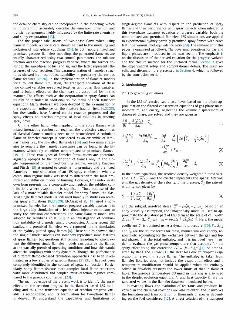
Fig. 8. Iso-contours (solid and dash-dot-dot lines) of joint normalized histogram of mixture fraction, Z against progress variable, C obtained in nonpremixed (top) and
premixed (bottom) flamelet calculations of three test flames, which are overlaid with the contours of reaction rate determined from the corresponding flamelet libraries.
Thick dash line indicates the region with significant reaction rate. Vertical dash line: location of stoichiometric mixture fraction Z st .
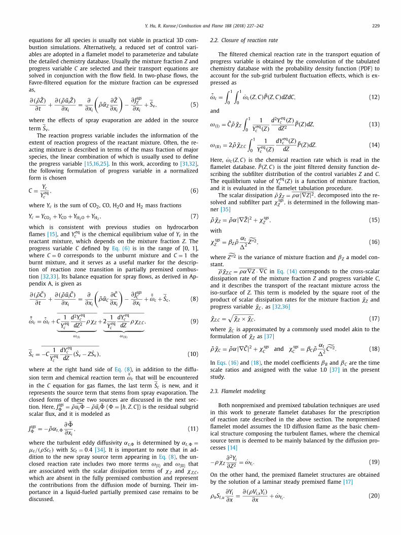
Fig. 9. Instantaneous field of spray evaporation rate for spray flame AcF6 from the
simulations with nonpremixed (left) and premixed (right) flamelet. The overlapped
solid-lines denote locations of the intense reaction region marked by Y OH × Y CH 2 O .
pilot stream. In the three flames investigated here, the mixture
fractions at the inlet determined based on the pre-vaporized fuel
and air flow rate listed in Table 1 are 0.146 (AcF3), 0.08 (AcF4)
and 0.094 (AcF6), which are reflected on the different initial points
with C = 0 in the A region for the three flames. Starting from this
initial premixed mixture, the spreading of possible reactant states
towards the upper region in Z − C space confirms the mixing pro-
cesses between the streams of main jet and hot pilot when mov-
ing farther downstream. Owing to the evaporative fuel addition
in the spray jet, a curved spreading domain, indicating this two-
stream interaction, is observed instead of a straight domain that
connects upper and lower regions directly which would be ex-
pected in gaseous flames with only the dominant effect of tur-
bulent mixing. In the B zone, a two-wing structure appears. The
lean branch delineates the entrainment of air coflow to the react-
ing mixture of the pilot, while at the rich side, the premixed mix-
tures end up fully burnt through a combustion trajectory affected
by the initial condition, droplet evaporation and turbulence.
In AcF3, as illustrated in the temperature profile of Fig. 3 , the
premixed flamelet shows an underpredicted temperature near the
axis region compared to the values obtained from the diffusion
flamelet and the experiments. The central flow temperature is
linked to the evolution trajectory of part A, as shown here for AcF3.
In the premixed case, the contour of reaction rate has a narrow
inverted-triangle distribution, and due to the lack of diffusion in
the Z direction for the area with low C , the evaporated fuel ex-
periences the inadequately predicted reaction progress rate. Near
the nozzle exit, the burning rate in the central flow is more like
diffusion controlled. Thus, the heat transfer between the neighbor-
ing mixed fuel/air pockets in this region is not taken into account
properly by the premixed flamelet database. Nevertheless, when
one moves downstream, even the nonpremixed flamelet leads to
a higher prediction of gas temperature, which indicates that no

Y. Hu, R. Kurose / Combustion and Flame 188 (2018) 227–242 237
Fig. 10. Contours of source terms in progress variable Eq. (8) from nonpremixed flamelet calculations of AcF6. (a): reaction rate ¯̇ ω c (left) and spray source term
¯̇ S c (right);
(b): source terms of ω (I) (left) and ω (II) (right), respectively. White solid line: isoline of stoichiometric mixture fraction.
single-regime flamelet that is derived from the scenario of asymp-
totic premixed or nonpremixed flames can appropriately simulate
the spray combustion. Spray flames under consideration, as dis-
cussed in the subsequent section, are characterized by a struc-
ture of evaporation-dominant reaction zones, presenting both non-
premixed and premixed behavior.
It should be also noted that in AcF4 under the lean condition,
the reaction path of spray jet mixtures initialized in the A zone
tends to reach upwards of the stoichiometric condition in the B
side through a straight line since AcF4 has the smallest liquid mass
loading at inlet among the three cases. Hence, the effect of spray
evaporation is not apparent in AcF4 with a small increment of mix-
ture fraction for unburnt central gases. Comparatively, AcF6 has a
similar amount of inlet premixed reactant but a much higher liq-
uid injection rate, resulting in the rich combustion of the central
fresh mixture in B zone with a curved reaction path. This explains
why the inner flame front starts earlier in AcF4 than in AcF6 as has
been revealed in Fig. 2 . If the spray effect is neglected for AcF6, its
combustion trajectory would be similar to that observed in AcF4,
where the central jet mixes quickly with the stoichiometric burn-
ing mixture in the pilot. This implies that evaporating droplets can
change the chemical structures of the flame significantly and leave
distinct footprints in the Z − C space.
4.2. Spray-reaction interaction
As demonstrated in above discussions, the accurate prediction
of spray flames is affected by the representative flamelet struc-
tures and the close coupling with sprays needs to be accounted for
with care. In this work, a form of the C governing equation newly
derived for two-phase flows is employed, accounting for the in-
fluence of spray/reaction interaction, a further analysis of which is
given below based on the predictions resulting from the two differ-
ent flamelet simulations of case AcF6 with the highest liquid mass
loading, and a similar observation can be made for two other spray
cases.
Figure 9 shows the pattern of spray evaporation interacting
with intense reaction regions (indicated by the isoline of Y OH ×Y CH 2 O
) in the nonpremixed (left) and premixed (right) flamelet
simulations of AcF6. As can be seen in the case of nonpremixed
flamelet simulation, the inner reaction zone occurs in the shear
layer which is directed inwards the central jet, where the hot pilot
transfers the heat to the spray mixture, promoting droplet evap-
oration close to the layer interface. In turn, the evaporation fuels
the reaction zone for further expansion. With increasing down-
stream distance, the central jet breaks down around x/D = 15 , fol-
lowing which combustion reaction establishes at the axis region
and subsequently enhances the interaction of the reaction with up-
coming sprays. For the premixed flamelet case, the reaction at the
inner side tends to be broader in space interacting with central
sprays. This can be related to the fact that premixed flamelet struc-
tures contain information regarding the species and heat fluxes in
progress variable space, promoting the propagation of the reaction
zone to the lower C area, which can be observed in Fig. 8 . Over-
all, in both nonpremixed and premixed flamelet computations, the
evaporating sprays show a pronounced interaction with reaction,
even though different patterns are observed.
To investigate the influence of spray effects on the reaction
progress, the contour of source terms in the two-phase C Eq. (8) is
shown in Figs. 10 and 11 . When a nonpremixed flamelet is con-
sidered, as displayed in Fig. 10 , it can be seen that the dominant
area of spray evaporation of ¯̇ S c overlaps with the intense reaction
zone of ¯̇ ω c in space, and in most areas especially within the in-
ner shear layer, the evaporation tends to decrease the local com-
bustion intensity with a negative ¯̇ S c and to slow the progress of
reactants to achieve equilibrium. A similar observation is made for
the premixed flamelet calculation in Fig 11 except for the broader
interaction zone for the spray and reaction. As for the terms of
ω (I) and ω (II) , they are not spray related, showing their main dis-
tribution out of the area where the interaction of spray/reaction
dominates. The term ω (I) associated with d 2 Y eq c / dZ 2 presents a
local maximum with a negative value along the stoichiometric
line, and it contributes mainly to flamelet reaction in a diffusion
mode [32] . On the other hand, ω (II) remains small with a pos-
itive value compared to ω (I) . Note that the model used in this
work for the cross-dissipation rate ˜ χZ,C in ω (II) may lead to the
overestimation of ˜ χZ,C [54] . Thus, it can be deduced that the in-
fluence of ω (I) and ω (II) is negligible in the present flames. How-
ever, as noted by Bray et al. [32] , this may need reconsidera-
tion in a partially premixed flame, where flame propagation is
highly affected by the closely coupled Z and C fields with a steeper
gradient.
238 Y. Hu, R. Kurose / Combustion and Flame 188 (2018) 227–242
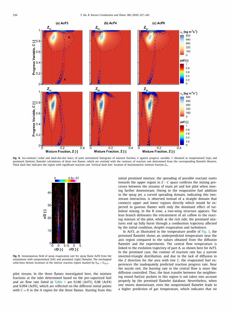
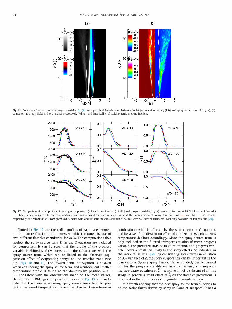
Fig. 11. Contours of source terms in progress variable Eq. (8) from premixed flamelet calculations of AcF6. (a): reaction rate ¯̇ ω c (left) and spray source term
¯̇ S c (right); (b):
source terms of ω (I) (left) and ω (II) (right), respectively. White solid line: isoline of stoichiometric mixture fraction.
Fig. 12. Comparison of radial profiles of mean gas temperature (left), mixture fraction (middle) and progress variable (right) computed for case AcF6. Solid and dash-dot
lines denote, respectively, the computations from nonpremixed flamelet with and without the consideration of source term
¯̇ S c . Dash and dot lines denote,
respectively, the computations from premixed flamelet with and without the consideration of source term
¯̇ S c . Dots: experimental data only available for temperature [29] .
Plotted in Fig. 12 are the radial profiles of gas-phase temper-
ature, mixture fraction and progress variable computed by use of
two different flamelet chemistries for AcF6. The computations that
neglect the spray source term
¯̇ S c in the C equation are included
for comparison. It can be seen that the profile of the progress
variable is shifted slightly outwards in the calculations with the
spray source term, which can be linked to the observed sup-
pression effect of evaporating sprays on the reaction zone (see
e.g., Figs. 10 and 11 ). The inward flame propagation is delayed
when considering the spray source term, and a subsequent smaller
temperature profile is found at the downstream position x/D =
30 . Consistent with the observations made on the mean values,
the results of RMS gas temperature shown in Fig. 13 also indi-
cate that the cases considering spray source term tend to pre-
dict a decreased temperature fluctuations. The reaction intense in
combustion region is affected by the source term in C equation,
and because of the dissipation effect of droplets the gas phase RMS
temperature declines accordingly. Since the spray source term is
only included in the filtered transport equation of mean progress
variable, the predicted RMS of mixture fraction and progress vari-
able shows a small sensitivity to the spray effects. As indicated in
the work of De et al. [28] by considering spray terms in equation
of SGS variance of Z , the spray evaporation can be important in the
lean cases of Sydney spray flames. The same study can be carried
out for the progress variable variance by deriving a correspond-
ing two-phase equation of ˜ C ′′ , which will not be discussed in this
study. In general a small effect of ¯̇ S c on the flamelet predictions is
observed in the dilute spray configuration considered here.
It is worth noticing that the new spray source term
¯̇ S c serves to
be the scalar fluxes driven by spray in flamelet subspace. It has a

Y. Hu, R. Kurose / Combustion and Flame 188 (2018) 227–242 239
Fig. 13. Comparison of radial profiles of RMS gas temperature (left), mixture fraction (middle) and progress variable (right) computed for case AcF6. Solid and dash-dot
lines denote, respectively, the computations from nonpremixed flamelet with and without the consideration of source term
¯̇ S c . Dash and dot lines denote,
respectively, the computations from premixed flamelet with and without the consideration of source term
¯̇ S c .
similar form as that found in the spray flamelet equation of species
mass fraction derived by Olguin and Gutheil [4] as S v (Z − 1) ∂Y i ∂Z
.
There, in a configuration of counterflowing spray flame, it was ob-
served that this source term arising from evaporation can domi-
nate the transport equation of products with a considerable contri-
bution to the dissipation. This is consistent with the findings of the
present work, and given that ¯̇ S c is one order of magnitude smaller
than
¯̇ ω c in this flame, a more apparent effect on chemical reactions
is expected for the implementation in dense sprays.
4.3. Combustion regime
In the above sections, it was shown that the chemical struc-
tures of spray flames can not be well captured by accessing a
single flamelet database from either the nonpremixed or pre-
mixed flamelet method. Below, the combustion regime in this pi-
loted spray flame is analyzed, and the calculations from the non-
premixed flamelet modeling of the three test flames are discussed.
For the investigation of flame structures, the flame index is a
useful tool, which is usually determined as the normalized product
of mass fraction gradient of fuel and oxidizer [55]
� = ∇ Y Fuel · ∇ Y O2 / |∇ Y Fuel ||∇ Y O2 | In correspondence with the premixed-like and diffusion-like reac-
tion regime, � takes a positive and negative value, respectively,
and its value locates within the region of ( −1,1).
The centerline distribution of mean temperature and mass frac-
tion of fuel and oxygen, as well as the evaporation rate and flame
index shown in Fig. 14 reveals that there exist three combus-
tion domains marked by a, b and c , where the diffusion and par-
tially premixed flame structures are coupled with the evaporation-
dominated regime. In the a region, the jet flow is more evapora-
tion dictated, featuring a small temperature but a slow increase of
fuel mass fraction. The evaporation of injected droplets is driven
by the initial momentum difference between the spray and gas
carrier and partly by the heating effect of the pilot stream, while
the heat diffused from the pilot is offset in a large part by the
heat loss because of droplet evaporation. When moving far away
from the nozzle exit, once the flow temperature starts to escalate
with a dramatic decrease of Y O2 , the transition to the b region of a
Fig. 14. Axial distribution of mean mass fraction of fuel (solid line) and oxygen
(dash line), mean temperature (dot line), spray evaporation term
˙ S v /10 0 0 (dash-dot
line) as well as flame index � (dash-dot-dot line) along the centerline for spray
flames AcF3, AcF4 and AcF6.
premixed-type flame is observed and the flame index increases
from negative to the positive value. The droplets in the core region
of the jet begin to evaporate faster and outstrip the consumption
of fuel in the preheat zone, leading to the continuous increase of
Y Fuel , which differs from the gaseous premixed flames. In a later
240 Y. Hu, R. Kurose / Combustion and Flame 188 (2018) 227–242
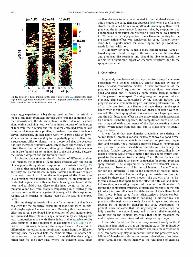
Fig. 15. Contour of flame index near the axis region. Isoline indicates the spray
region with significant evaporation. Filled dots: representative droplets in the flow
field colored by their individual evaporate rate.
stage, Y Fuel experiences a big slump resulting from the establish-
ment of the main premixed burning zone near the centerline. Fur-
ther downstream, the diffusion flame in the c domain develops
along with a declining negative flame index because of the leakage
of fuel from the b region and the oxidizer entrained from coflow.
In terms of temperature profiles, a dual-reaction structure is ob-
served, particularly in lean flame AcF4, with two peaks at down-
stream locations corresponding to the partially premixed flame and
a subsequent diffusion flame. It is also observed that the evapora-
tion rate increases promptly when sprays reach the vicinity of pre-
mixed flame front in b domain, although a relatively high evapora-
tion is also found close to the inlet due to the slip velocity between
the injected droplets and the turbulent flow.
For further understanding the distribution of different combus-
tion regimes, the contour of flame index overlaid with the isoline
of a region with significant evaporation is illustrated in Fig. 15 .
It is clear that mixed burning regimes exist in this spray flame,
and they are placed closely in space, forming multilayer coupled
flame structures. Apart from the middle part of the flame zone
in a premixed-type indicated by the positive �, an evaporation-
controlled regime and diffusion flame burning are found at the
near- and far-field areas. Close to the inlet, owing to the accu-
mulated vapor fuel from droplets evaporating in a relatively low
temperature condition, a negative � is assigned to the evaporation
regime, which reaches its intense region at the base of premixed
flame.
This multi-regime reaction in spray flame presents a significant
challenge for the predictive capability of modeling based on clas-
sical single-regime flamelet methods. Knowing this, one research
effort proposed a combined implementation of both nonpremixed
and premixed flamelets in a single simulation by identifying the
local combustion mode with flame index and reasonable results
were obtained in the simulations of gas flames [16,23,31] . As in-
dicated in this work, however, the simple form of � can fail to
differentiate the evaporation-dominated regime from the diffusion
burning since they could hold the same negative �. Another at-
tempt resorts to the establishment of a model flamelet configu-
ration that fits the spray case, where the inherent spray effect
on flamelet structures is incorporated in the tabulated chemistry.
This includes the spray flamelet approach [56] , where the flamelet
structures, obtained from a counterflow diffusion spray flame, well
predicted the turbulent spray flames controlled by evaporation and
nonpremixed combustion. An extension of this model was attained
in [26] when a partially premixed spray flame accounting for the
pre-vaporization effect was considered for spray flamelet gener-
ation, but its performance for various spray and gas conditions
needs further validation.
In summary, for spray flames a more comprehensive flamelet-
based approach should recognize the coexistence of diffusion-like
and premixed-like reactions and should be able to include the
regime with significant impact on chemical structures due to the
spray evaporation.
5. Conclusions
Large eddy simulations of partially premixed spray flame were
performed with detailed chemistry effects included by use of
flamelet-based combustion models. A new formulation of the
progress variable C equation for two-phase flows was devel-
oped and used, and it includes a spray source term in contrast
to the gaseous counterpart. The single-regime nonpremixed and
premixed flamelets parameterized by the mixture fraction and
progress variable were both adopted, and their performance in LES
of partially premixed spray flames and dependency on the spray
effect when including the proposed two-phase C equation were ex-
amined. The dilute spray phase was modeled in a Lagrangian way,
and the SGS fluctuation effect on the evaporation was incorporated
by a refined stochastic approach. The computations were discussed
and compared with experiments of the Sydney reacting acetone
sprays, which range from rich and lean to stoichiometric operat-
ing conditions.
It was found that two flamelet predictions considering the
source term of progress variable generally showed a good agree-
ment with the measurements in terms of gas temperature, droplet
size, and velocity. Yet a marked difference between nonpremixed
and premixed flamelet calculations was observed. Generally, the
premixed flamelet captured the downstream jet spreading in the
radial direction while overestimating the peak temperature com-
pared to the non-premixed chemistry. The diffusion flamelet, on
the other hand, yielded an earlier combustion for central premixed
spray mixtures. The disagreement between two flamelet simula-
tions tends to become small in the stoichiometric flame. The rea-
son for this difference is due to the difference of reaction propa-
gation in the mixture fraction and progress variable subspace in-
dicated by these two flamelet models. The analysis of Z − C his-
tograms showed that apart from the effect of diffusion and chem-
ical reaction, evaporating droplets add another free dimension af-
fecting the combustion trajectory of premixed reactants in the core
jet, which in turn influences the stabilization of inner flame front.
Thus, these Sydney spray flames characterize a hybrid combus-
tion regime, where combustions occurring in diffusion-like and
premixed-like regimes are closely located in space and strongly
coupled by the turbulent transport and spray evaporation. The
present study indicated that the single-regime flamelet can not
fully describe the spray flames, and a more reliable modeling
would rely on the flamelet structures that should recognize the
multi-regime reactions interacted with evaporating sprays.
It was also found that the new spray source term
˙ S c in the C
equation is identified to act as an important scalar flux induced by
spray evaporation in flamelet structures and thus the incorporation
of ˙ S c can potentially play an important role in the predictive capa-
bilities of flamelet models. In the present calculations of turbulent
spray flame, it contributed mainly to the retardation of chemical

Y. Hu, R. Kurose / Combustion and Flame 188 (2018) 227–242 241
reactions and slow down the flame propagation towards the inner
jet. In both nonpremixed and premixed flamelet simulations, the
major impact area of ˙ S c overlaps with the area of main reaction
regime. Although its effect on the chemical reactions is small in
the present dilute sprays, a future study on its implementation in
dense sprays is warranted.
Acknowledgments
This research was partially supported by MEXT (Ministry of Ed-
ucation, Culture, Sports, Science, and Technology) as ′ ′ Priority is-
sue on Post-K computer ′ ′ (Accelerated Development of Innovative
Clean Energy Systems), and by MEXT Grant in Aid (No. 16H04278 ).
Y.H. thanks Prof. A.R. Masri at the University of Sydney for provid-
ing the experimental measurements.
Appendix A. Transport equation of reaction progress variable
for reacting spray flows
For the flamelet-based tabulation technique, the species mass
fraction Y i can be expressed directly in terms of the mixture frac-
tion Z and progress variable C as
Y i (x , t) = Y i [ Z(x , t) , C(x , t)] (37)
The formulations for the temporal and spatial derivatives of Y i ( x , t )
can then be written as
∂ t Y i = ∂ Z Y i ∂ t Z + ∂ C Y i ∂ t C, (38)
∇ Y i = ∂ Z Y i ∇ Z + ∂ C Y i ∇ C. (39)
By multiplying Eqs. (38) and (39) with the gas density ρ and mass
flux ρu , respectively, and combining the resulting equations, after
rearranging terms, we obtain
ρ∂C
∂t + ρu · ∇C =
(ρD t Y i − ρD t Z
∂Y i ∂Z
)· 1
∂ Y i /∂ C , (40)
where D t = ∂ t + u · ∇ is the substantial derivative.
The use of the governing equations of the species mass fraction
Y i and the mixture fraction Z for multiphase flows
ρ∂Y i ∂t
+ ρu · ∇Y i = ∇ · (ρα∇Y i ) + ˙ ω i +
˙ S Y i − Y i ˙ S v (41)
ρ∂Z
∂t + ρu · ∇Z = ∇ · (ρα∇Z) +
˙ S v − Z ̇ S v , (42)
in the above derived equation for the progress variable C , Eq. (40) ,
yields
ρ∂C
∂t + ρu · ∇C =
(ρα∇
2 Y i + ˙ ω i +
˙ S Y i − Y i ˙ S v ) 1
∂ Y i /∂ C
− ∂Y i ∂Z
(ρα∇
2 Z +
˙ S v − Z ̇ S v ) 1
∂ Y i /∂ C . (43)
On the right hand side, S v is the mass source term associated with
vaporization. S Y i is the production rate of species Y i due to evap-
oration processes. For the single component spray droplets, S Y i is
zero except in the case of Y i = Y f uel . ˙ ω i is the chemical reaction
rate. Here, the assumption of a constant diffusion coefficient α is
adopted. Y i can denote the mass fraction of a single species or
a sum of multiple species; for the latter case, the assumption of
equal diffusion coefficients for all species considered is addition-
ally used to ensure the same form of Eq. (41) .
The progress variable C in a normalized form is usually defined
by [31,32]
C = Y i (x , t) /Y eq i
(Z(x , t)) (44)
with Y eq i
(Z(x , t)) being the corresponding equilibrium value of
species mass fraction and being a function of only the mixture
fraction Z , which implies
∂Y i ∂C
= Y eq i
, ∂ 2 Y i ∂C 2
= 0
∂ 2 Y i ∂ C∂ Z
=
dY eq i
dZ ,
∂ 2 Y i ∂Z 2
= C d 2 Y eq
i
dZ 2 (45)
By Inserting of the following formulation of ∇
2 Y i
∂
∂x i
(∂Y i ∂x i
)=
∂
∂x i
(∂Y i ∂C
∂C
∂x i +
∂Y i ∂Z
∂Z
∂x i
)
=
∂Y i ∂C
∂ 2 C
∂ x i 2 +
∂Y i ∂Z
∂ 2 Z
∂ x i 2 +
∂ 2 Y i ∂C 2
(∂C
∂x i
)2
+
∂ 2 Y i ∂Z 2
(∂Z
∂x i
)2
+ 2
∂ 2 Y i ∂ C∂ Z
∂C
∂x i
∂Z
∂x i (46)
and Eq. (45) into Eq. (43) , the transport equation of the progress
variable C for spray flows can finally be reformulated to
∂ t (ρC) + ∇ · (ρu C) −∇ · (ρα∇C)
=
[ ˙ ω i + C
d 2 Y eq i
dZ 2 ρχZ + 2
dY eq i
dZ ρχZ,C
] 1
Y eq i
−[
C dY eq
i
dZ ( ̇ S v − Z ̇ S v )
] 1
Y eq i
, (47)
the last term of which represents the source term derived from
the effects of spray vaporization. χZ = α|∇Z| 2 and χZ,C = α∇ Z · ∇ C
are the scalar dissipation rate of mixture fraction and the cross-
dissipation term, respectively.
References
[1] Y. Baba , R. Kurose , Analysis and flamelet modeling for spray combustion, J. Fluid Mech. 612 (2008) 45–79 .
[2] P. Jenny , D. Roekaerts , N. Beishuizen , Modeling of turbulent dilute spray com- bustion, Prog. Energy Combust. Sci. 38 (2012) 846–887 .
[3] M.S. Raju , On the importance of chemistry/turbulence interactions in spray computations, Numer. Heat. Tr. B-Fund. 41 (2002) 409–432 .
[4] H. Olguin , E. Gutheil , Influence of evaporation on spray flamelet structures,
Combust. Flame 161 (2014) 987–996 . [5] S. Ukai , A. Kronenburg , O.T. Stein , LES-CMC of a dilute acetone spray flame,
Proc. Combust. Inst. 34 (2013) 1643–1650 . [6] A. Rittler , F. Proch , A.M. Kempf , LES of the sydney piloted spray flame series
with PFGM/ATF approach and different sub-filter models, Combust. Flame 162 (2015) 1575–1598 .
[7] E. Abtahizadeh , L.P.H. De Goey , J.A.V. Oijen , LES of delft jet-in-hot coflow
burner to investigate the effect of preferential diffusion on autoignition of CH4/h2 flames, Fuel 191 (2017) 36–45 .
[8] N. Patel , S. Menon , Simulation of spray-turbulence-flame interactions in a lean direct injection combustor, Combust. Flame 153 (2008) 228–257 .
[9] V.N. Prasad , A.R. Masri , S.N. Martinez , K.H. Luo , Investigation of auto-ignition in turbulent methanol spray flames using large eddy simulation, Combust. Flame
160 (2013) 2941–2954 .
[10] Y. Pei , E.R. Hawkes , S. Kook , G.M. Goldin , T. Lu , Modelling n-dodecane spray and combustion with the transported probability density function method,
Combust. Flame 162 (2015) 2006–2019 . [11] X. Jiang , G. Siamas , K. Jagus , T. Karayiannis , Physical modelling and advanced
simulations of gas– liquid two-phase jet flows in atomization and sprays, Prog. Energy Combust. Sci. 36 (2010) 131–167 .
[12] S.B. Pope , Small scales, many species and the manifold challenges of turbulent
combustion, Proc. Combust. Inst. 34 (2013) 1–31 . [13] A. Giusti , E. Mastorakos , Detailed chemistry LES/CMC simulation of a swirling
ethanol spray flame approaching blow-off, Proc. Combust. Inst. 36 (2017) 2625–2632 .
[14] N. Peters , Laminar diffusion flamelet models in non-premixed turbulent com- bustion, Prog. Energy Combust. Sci. 10 (1984) 319–339 .
[15] M. Ihme , H. Pitsch , Prediction of extinction and reignition in nonpremixed tur- bulent flames using a flamelet/progress variable model. 2. application in LES
of Sandia flames d and, E, Combust. Flame 155 (2008) 90–107 .
[16] B. Fiorina , O. Gicquel , L. Vervisch , S. Carpentier , N. Darabiha , Approximating the chemical structure of partially premixed and diffusion counterflow flames
using FPI flamelet tabulation, Combust. Flame 140 (2005) 147–160 . [17] J.A. van Oijen , L.P.H. de Goey , Modelling of premixed laminar flames using
flamelet-generated manifolds, Combust. Sci. Technol. 161 (20 0 0) 113–137 .

242 Y. Hu, R. Kurose / Combustion and Flame 188 (2018) 227–242
[18] E. Knudsen , Shashank , H. Pitsch , Modeling partially premixed combustion be- havior in multiphase LES, Combust. Flame 162 (2015) 159–180 .
[19] H.A . EI-Asrag , A .C. Iannetti , S.V. Apte , Large eddy simulations for radia- tion-spray coupling for a lean direct injector combustor, Combust. Flame 161
(2014) 510–524 . [20] S. Tachibana , K. Saito , T. Yamamoto , M. Makida , T. Kitano , R. Kurose , Experi-
mental and numerical investigation of thermo-acoustic instability in a liquid–fuel aero-engine combustor at elevated pressure: validity of large-eddy simu-
lation of spray combustion, Combust. Flame 162 (2015) 2621–2637 .
[21] A .W. Vreman , B.A . Albrecht , J.A . van Oijen , L.P. de Goey , R.J.M. Bastiaans , Pre- mixed and nonpremixed generated manifolds in large-eddy simulation of san-
dia flame d and f, Combust. Flame 153 (2008) 394–416 . [22] W.J.S. Ramaekers , J.A. van Oijen , L.P.H. de Goey , A priori testing of flamelet
generated manifolds for turbulent partially premixed methane/air flames, Flow
Turbul. Combust. 84 (2010) 439–458 .
[23] P. Domingo , L. Vervisch , J. Réveillon , DNS analysis of partially premixed com-
bustion in spray and gaseous turbulent flame-bases stabilized in hot air, Com- bust. Flame 140 (2005) 172–195 .
[24] S. Subramaniam , Lagrangian-eulerian methods for multiphase flows, Prog. En- ergy Combust. Sci. 39 (2013) 215–245 .
[25] C.D. Pierce , P. Moin , Progress-variable approach for large-eddy simulation of non-premixed turbulent combustion, J. Fluid Mech. 504 (2004) 73–97 .
[26] Y. Hu , H. Olguin , E. Gutheil , A spray flamelet/progress variable approach com-
bined with a transported joint PDF model for turbulent spray flames, Combust. Theory Model. 21 (2017) 575–602 .
[27] J. Réveillon , L. Vervisch , Spray vaporization in nonpremixed turbulent combus- tion modeling: a single droplet model, Combust. Flame 121 (20 0 0) 75–90 .
[28] S. De , S.H. Kim , Large eddy simulation of dilute reacting sprays: droplet evap- oration and scalar mixing, Combust. Flame, 160 (2013) 2048–2066 .
[29] J.D. Gounder , A. Kourmatzis , A.R. Masri , Turbulent piloted dilute spray flames:
flow fields and droplet dynamics, Combust. Flame 159 (2012) 3372–3397 . [30] D.K. Lilly , A proposed modification of the Germano subgridscale closure
method, Phys.Fluids A 4 (1992) 633–635 . [31] P. Domingo , L. Vervisch , K. Bray , Partially premixed flamelets in LES of non-
premixed turbulent combustion, Combust. Theory Model. 6 (2002) 529–551 . [32] K. Bray , P. Domingo , L. Vervisch , Role of the progress variable in models for
partially premixed turbulent combustion, Combust. Flame 141 (2005) 431–437 .
[33] J.B. Michel , O. Colin , C. Angelberger , D. Veynante , Using the tabulated diffusion flamelet model ADF-PCM for simulating a lifted methaneair jet flame, Com-
bust. Flame 156 (2009) 1318–1331 . [34] H. Pitsch , H. Steiner , Large-eddy simulation of a turbulent piloted methane/air
diffusion flame (Sandia flame d), Phys. Fluids 12 (20 0 0) 2541–2554 . [35] C.D. Pierce , P. Moin , A dynamic model for subgrid variance and dissipation rate
of a conserved scalar, Phys. Fluids 10 (1998) 3041 .
[36] P.-D. Nguyen , V. L , V. Subramanian , P. Domingo , Multidimensional flamelet–generated manifolds for partially premixed combustion, Combust. Flame 157
(2010) 43–61 . [37] M.M. Salehi , W.K. Bushe , N. Shahbazian , C.P.T. Groth , Modified laminar flamelet
presumed probability density function for LES of premixed turbulent combus- tion, Proc. Combust. Inst. 34 (2013) 1203–1211 .
[38] H. Pitsch, Flamemaster v3.1: A c++ computer program for 0d combustion and 1d laminar flame calculations, 1998.
[39] M. Chrigui , J. Gounder , A. Sadiki , A.R. Masri , J. Janicka , Partially premixed re- acting acetone spray using LES and FGM tabulated chemistry, Combust. Flame
159 (2012) 2718–2741 . [40] M. Chrigui , A.R. Masri , A. Sadiki , J. Janicka , Acetone droplet behavior in reacting
and non-reacting turbulent flow, Flow Turbul. Combust. 90 (2013) 813–832 . [41] L. Ma , B. Naud , D. Roekaerts , Transported PDF modeling of ethanol spray in
hot-diluted coflow flame, Flow Turbul. Combust. 96 (2016) 469–502 . [42] D.C. Haworth , Progress in probability density function methods for turbulent
reacting flows, Prog. Energy Combust. Sci. 36 (2010) 168–259 .
[43] R.S. Miller , K. Harstad , J. Bellan , Evaluation of equilibrium and non-equilibrium
evaporation models for many-droplet gas-liquid flow simulations, Int. J. Mul-
tiph. Flow 24 (1998) 1025–1055 . [44] M. Bini , W.P. Jones , Large-eddy simulation of particle-laden turbulent flows, J.
Fluid Mech. 614 (2008) 207–252 . [45] T. Kitano , J. Nishio , R. Kurose , S. Komori , Effects of ambient pressure, gas tem-
perature and combustion reaction on droplet evaporation, Combust. Flame 161
(2014) 551–564 . [46] C. Heye , V. Raman , A.R. Masri , Influence of spray/combustion interactions
on auto-ignition of methanol spray flames, Proc. Combust. Inst. 35 (2015) 1639–1648 .
[47] T. Kitano , K. Kaneko , R. Kurose , S. Komori , Large-eddy simulations of gas- and liquid-fueled combustion instabilities in back-step flows, Combust. Flame, 170
(2016) 63–78 .
[48] T. Hara , M. Muto , T. Kitano , R. Kurose , S. Komori , Direct numerical simula- tion of a pulverized coal jet flame employing a global volatile matter reaction
scheme based on detailed reaction mechanism, Combust. Flame 162 (2015) 4391–4407 .
[49] S. Pichon , G. Black , N. Chaumeix , M. Yahyaoui , H.J. Curran , J.M. Simmie , R. Donohue , The combustion chemistry of a fuel tracer: measured flame
speeds and ignition delays and a detailed chemical kinetic model for the oxi-
dation of acetone, Combust. Flame 156 (2009) 494–504 . [50] R.W. Bilger , A mixture fraction framework for the theory and modeling of
droplets and sprays, Combust. Flame 158 (2011) 191–202 . [51] M. Klein , A. Sadiki , J. Janicka , A digital filter based generation of inflow data
for spatially developing direct numerical or large eddy simulations, J. Comput. Phys. 186 (2003) 652–665 .
[52] Y. Hu , H. Olguin , E. Gutheil , Transported joint probability density function sim-
ulation of turbulent spray flames combined with a spray flamelet model us- ing a transported scalar dissipation rate, Combust. Sci. Technol. 189 (2017)
322–339 . [53] M. Juddoo , A.R. Masri , S.B. Pope , Turbulent piloted partially-premixed flames
with varying levels of o-2/n-2: stability limits and PDF calculations, Combust. Theory Model. 15 (2011) 773–793 .
[54] S.P. Malkeson , N. Chakraborty , Statistical analysis of cross scalar dissipation
rate transport in turbulent partially premixed flames: a direct numerical sim- ulation study, Flow Turbul. Combust. 87 (2011) 313–349 .
[55] H. Yamashita , M. Shimada , T. Takeno , A numerical study on flamestability at the transition point of jet diffusion flames, Symp. (Int.) Combust. 26 (1996)
27–34 . [56] C. Hollmann , E. Gutheil , Flamelet-modeling of turbulent spray diffusion flames
based on a laminar spray flame library, Combust. Sci. Technol. 135 (1998) 175–192 .