nonlinear structural analysis - ait...
TRANSCRIPT

Nonlinear Structural Analysis
Designing for Safer InfrastructureInnovative design that goes beyond the codes
1 – 2 June 2018Asian Institute of Technology, Thailand
Shabir Talpur

2
PBD Guidelines• PEER 2017/06, “Tall Building Initiative,
Guidelines for Performance Based
Seismic Design of Tall Buildings”
• PEER/ATC 72-1, “Modeling and
Acceptance Criteria for Seismic Design
and Analysis of Tall Buildings”
• ASCE/SEI 41-13, “Seismic Evaluation
and Retrofit of Existing Buildings”
• LATBSDC 2017, “An Alternative
Procedure for Seismic Analysis and
Design of Tall Buildings Located in the
Los Angeles Region”

3
Classification of Structural Actions• All actions must be classified as either
Deformation-controlled, or
Force-controlled
Deformation-controlled action – An action expected to undergo nonlinear behavior in response to earthquake shaking.
Force-controlled action – An action that is not expected to undergo nonlinear behavior in response to earthquake shaking.

4
Examples of Deformation-controlled Actions
Source: 2017 LATBSDC

5
Types of Nonlinear Component Models • Typically there are two types of nonlinear component models used in commercial
software.
• Concentrated Hinge Component Model
• Fiber-Type Component Model

6
Concentrated Hinge Model

7
Monotonic versus Cyclic Envelope
Source: ATC 72-1

8
Backbone Curves
Option 1Cyclic and in-cycle degradation explicitly modeled during analysis; backbone curve hardens/softens as a function of damage
Option 2Post-peak capping and cyclic degradation modeled with fixed backbone curve that remains fixed during analysis; backbone curve is defined based on measured(data) or assumed cyclic softening.
Option 3Model captures cyclic degradation, but post-peak softening is not modeled; and ultimate limit state is imposed to avoid unconservative analysis in post-peak realm
Backbone Curves Model Types (PEER TBI & ATC 72-1)

9
Option 2Generalized Component Response
• Response curves in ASCE 41 are essentially the same as "Option 2”
– cyclic envelope fit to cyclic test data
– ASCE 41 (FEMA 273) originally envisioned for static pushover analysis without any cyclic deformation in the analysis
• Option 2/ASCE 41: reasonable for most Commercial analysis programs that cannot simulate cyclic degradation of the backbone curve
• Post-Peak Response: dashed line connecting points C-E in ASCE 41 response curve is more reasonable representation of post-peak (softening) response

10
ASCE 41 Beam Modeling Parameters and Acceptance Criteria

11
ASCE 41 Column Modeling Parameters and Acceptance Criteria

12
Column Rotation
Force
Deformation
Vp/Vo ≤ 0.6
Vp/Vo > 1.0
0.6 ≤ Vp/Vo ≤ 1.0

13
ATC 72 Recommended Modeling Parameters
Key Design/Detailing Variables:ρsh – amount of steel stirrupsρ – amount of Longitudinal steelν – axial load ratio(P/Agfc’)asl – joint bond slipsn – tie spacing
• Values given by the equations are initial monotonic backbone curve.• To convert monotonic backbone curve to cyclic envelope curve reduction factors are recommended
ϴp,cyclic = 0.7ϴp
ϴpc,cyclic=0.7ϴpc
14
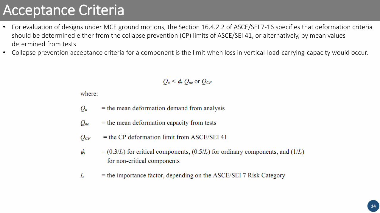
Acceptance Criteria• For evaluation of designs under MCE ground motions, the Section 16.4.2.2 of ASCE/SEI 7-16 specifies that deformation criteria
should be determined either from the collapse prevention (CP) limits of ASCE/SEI 41, or alternatively, by mean values determined from tests
• Collapse prevention acceptance criteria for a component is the limit when loss in vertical-load-carrying-capacity would occur.

15
Joint Modeling

16
Modeling of Structural Components: RC Shear Walls RC Shear Walls
• Preferred Model: Fiber wall panels
• Thing to keep in mind
‒ Fiber models are only nonlinear in axial flexure(P-M3)
‒ Flexural stiffness is derived from specified material stress stains
‒ Shear in fiber models is generally modelled as elastic
‒ Fiber predict the flexural response reasonably well
‒ Fiber models may not predict strength degradation (and ultimately, failure) well
‒ Strain predicted by fiber model are sensitive to material stress strains and fiber element discretization

17
Modeling of Structural Components: RC Shear Walls
Strain Ɛ=δ/L

18
Fiber model Strain Prediction
Source: ATC 72-1

19
Influence of Reinforcing Steel Stress-Strain Relation
Source: ATC 72-1

20
Fiber Model Wall Meshing SensitivitySource: ATC 72-1

21
Reinforcement Tensile Strain vs Shear Capacity
Source: 2017 LATBSDC

22
Coupling Beam• Bending of shear wall can induce a lot of
deformations in coupling beam.
• A consistent finding from coupling beam studies is that the use of diagonal reinforcement improves the cyclic performance of beams with clear span-to-depth ratios r less than four.
• For ratios greater than four, use of diagonal reinforcement is not practical given the shallow angle of the bars
• For modeling of coupling beams lumped plasticity models i.e. moment hinge or shear hinge are capable of producing test results with reasonable accuracy
• UCLA-SGEL Report 2009/06 and ASCE 41-13 are good resources

23
Coupling Beam Model Calibration
Source: ATC 72-1

24
Coupling Beam Back Bone Comparision
0
0.2
0.4
0.6
0.8
1
1.2
1.4
0 0.02 0.04 0.06 0.08 0.1
V/V
nco
de
Rotation (rad)
ASCE 41
UCLA
ASCE 41 CP Limit

25
Slab-column Frame Components• Flat slabs are very popular in tall
buildings these days.
• Effective slab beam model can be used to capture coupling between slab-column frame
• Modeling of slab-column frames involves assigning appropriate stiffness and strength
• Nonlinear hinges can be used in the effective slab beams following the recommendations ASCE 41

26
Effective Slab Beam Model
α: Effective Beam Width Factorβ: Coefficient accounting for Cracking
αl2 = 2c1 + l1/3 for Interior Frames
β= 4c1 /l1≥ 1/3 for RC Slabsβ= 1/2 for PT

27
Nonlinear Modeling ParametersASCE 41-13 Table 10-15

28
Salient Points on Slab-Column Frame Modeling
• Vg in ASCE41-13 Table has to be calculated from load combination 1.2DL + 0.5 LL
• Slab Beam Moment Capacity = MnCS - MgCS
MnCS = the design flexural strength of the column strip
MgCS = the column strip moment caused by gravity loads
• If Slab-column frame are not modeled
‒ the potential adverse impacts of additional axial load induced on the gravity
system columns should be considered
‒ Punching shear failure possibilities can still be checked following the requirments
of ACI 318-14 18.14.5.1

29
Back Stay Effect• Backstay effects are the transfer of lateral forces from
the seismic-force resisting elements in the tower into additional elements that exist within the podium
• The lateral force resistance in the podium levels, and force transfer through floor diaphragms at these levels, helps a tall building resist seismic overturning forces
• Force transfer is sensitive to podium diaphragm stiffness assumption.
• The UB analysis provides an upper-bound estimate of forces in the backstay load path and a lower bound estimate of forces in the foundation below the tower
• The LB analysis provides a lower-bound estimate of forces in the backstay load path and an upper-bound estimate of forces in the foundation below the tower.

30
Remaining Information•2.5% Viscous damping is generally used in the nonlinear model
to account for unmodeled energy dissipation
•Model the effects of expected gravity loads in the nonlinear analysis using the load combination D + 0.5L, where L is 80% of unreduced live loads that exceed 100 pounds-per-square-foot (4.79 kN/m2) and 40% of other unreduced live loads.
• Include the seismic mass of the entire building in the model, including both the superstructure and below-grade structure

31
Global Acceptance Criteria
•Analytical solution fails to converge.
•Peak transient story drift ratio in any story exceeds 0.045;
•Residual story drift ratio in any story exceeds 0.015
•Demands on deformation-controlled elements exceed the valid range of modeling

Shabir Talpur
Thank you