non traditional manufacturing processes- an · pdf filenon traditional manufacturing...
TRANSCRIPT
NON TRADITIONAL MANUFACTURING PROCESSES- An overview
Introduction
Non-traditional manufacturing processes is defined as a group of processes that remove
excess material by various techniques involving mechanical, thermal, electrical or chemical
energy or combinations of these energies but do not use a sharp cutting tools as it needs to be
used for traditional manufacturing processes.
Extremely hard and brittle materials are difficult to machine by traditional machining
processes such as turning, drilling, shaping and milling. Non traditional machining processes,
also called advanced manufacturing processes, are employed where traditional machining
processes are not feasible, satisfactory or economical due to special reasons as outlined
below.
• Very hard fragile materials difficult to clamp for traditional machining
• When the work piece is too flexible or slender
• When the shape of the part is too complex
Several types of non-traditional machining processes have been developed to meet extra
required machining conditions. When these processes are employed properly, they offer
many advantages over non-traditional machining processes. The common non-traditional
machining processes are described in this section.
Electrical Discharge Machining (EDM)
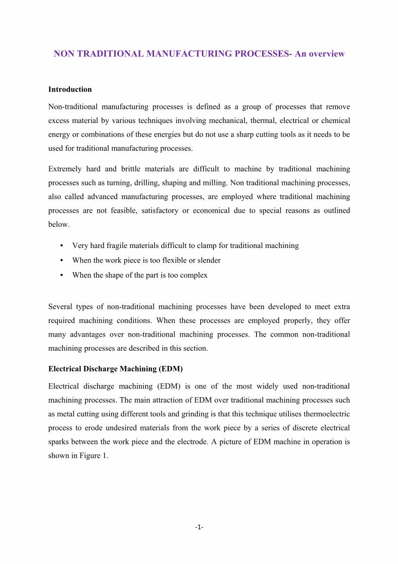
Electrical discharge machining (EDM) is one of the most widely used non-traditional
machining processes. The main attraction of EDM over traditional machining processes such
as metal cutting using different tools and grinding is that this technique utilises thermoelectric
process to erode undesired materials from the work piece by a series of discrete electrical
sparks between the work piece and the electrode. A picture of EDM machine in operation is
shown in Figure 1.
-1-
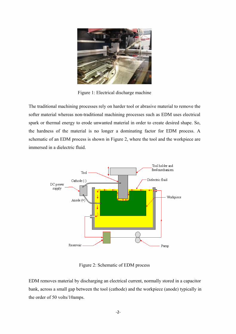
Figure 1: Electrical discharge machine
The traditional machining processes rely on harder tool or abrasive material to remove the
softer material whereas non-traditional machining processes such as EDM uses electrical
spark or thermal energy to erode unwanted material in order to create desired shape. So,
the hardness of the material is no longer a dominating factor for EDM process. A
schematic of an EDM process is shown in Figure 2, where the tool and the workpiece are
immersed in a dielectric fluid.
Figure 2: Schematic of EDM process
EDM removes material by discharging an electrical current, normally stored in a capacitor
bank, across a small gap between the tool (cathode) and the workpiece (anode) typically in
the order of 50 volts/10amps.
-2-
Application of EDM
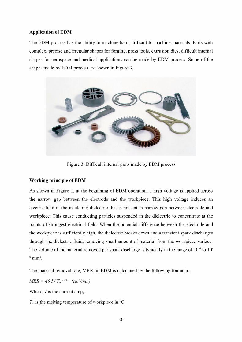
The EDM process has the ability to machine hard, difficult-to-machine materials. Parts with
complex, precise and irregular shapes for forging, press tools, extrusion dies, difficult internal
shapes for aerospace and medical applications can be made by EDM process. Some of the
shapes made by EDM process are shown in Figure 3.
Figure 3: Difficult internal parts made by EDM process
Working principle of EDM
As shown in Figure 1, at the beginning of EDM operation, a high voltage is applied across
the narrow gap between the electrode and the workpiece. This high voltage induces an
electric field in the insulating dielectric that is present in narrow gap between electrode and
workpiece. This cause conducting particles suspended in the dielectric to concentrate at the
points of strongest electrical field. When the potential difference between the electrode and
the workpiece is sufficiently high, the dielectric breaks down and a transient spark discharges
through the dielectric fluid, removing small amount of material from the workpiece surface.
The volume of the material removed per spark discharge is typically in the range of 10-6 to 10-
6 mm3.
The material removal rate, MRR, in EDM is calculated by the following foumula:
MRR = 40 I / Tm 1.23 (cm3/min)
Where, I is the current amp,
Tm is the melting temperature of workpiece in 0C
-3-
Advantages of EDM
The main advantages of DM are:
• By this process, materials of any hardness can be machined;
• No burrs are left in machined surface;• One of the main advantages of this process is that thin and fragile/brittle components
can be machined without distortion;
• Complex internal shapes can be machined
Limitations of EDM
The main limitations of this process are:
• This process can only be employed in electrically conductive materials;
• Material removal rate is low and the process overall is slow compared to conventional
machining processes;
• Unwanted erosion and over cutting of material can occur;
• Rough surface finish when at high rates of material removal.
Dielectric fluids
Dielectric fluids used in EDM process are hydrocarbon oils, kerosene and deionised water.
The functions of the dielectric fluid are to:
• Act as an insulator between the tool and the workpiece.
• Act as coolant.
• Act as a flushing medium for the removal of the chips.
The electrodes for EDM process usually are made of graphite, brass, copper and copper-
tungsten alloys.
Design considerations for EDM process are as follows:
• Deep slots and narrow openings should be avoided.
• The surface smoothness value should not be specified too fine.
• Rough cut should be done by other machining process. Only finishing operation
should be done in this process as MRR for this process is low.
-4-
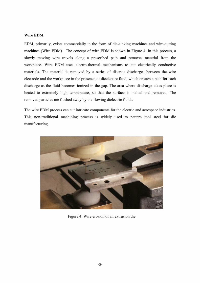
Wire EDM
EDM, primarily, exists commercially in the form of die-sinking machines and wire-cutting
machines (Wire EDM). The concept of wire EDM is shown in Figure 4. In this process, a
slowly moving wire travels along a prescribed path and removes material from the
workpiece. Wire EDM uses electro-thermal mechanisms to cut electrically conductive
materials. The material is removed by a series of discrete discharges between the wire
electrode and the workpiece in the presence of dieelectirc fluid, which creates a path for each
discharge as the fluid becomes ionized in the gap. The area where discharge takes place is
heated to extremely high temperature, so that the surface is melted and removed. The
removed particles are flushed away by the flowing dielectric fluids.
The wire EDM process can cut intricate components for the electric and aerospace industries.
This non-traditional machining process is widely used to pattern tool steel for die
manufacturing.
Figure 4: Wire erosion of an extrusion die
-5-
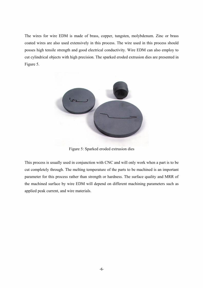
The wires for wire EDM is made of brass, copper, tungsten, molybdenum. Zinc or brass
coated wires are also used extensively in this process. The wire used in this process should
posses high tensile strength and good electrical conductivity. Wire EDM can also employ to
cut cylindrical objects with high precision. The sparked eroded extrusion dies are presented in
Figure 5.
Figure 5: Sparked eroded extrusion dies
This process is usually used in conjunction with CNC and will only work when a part is to be
cut completely through. The melting temperature of the parts to be machined is an important
parameter for this process rather than strength or hardness. The surface quality and MRR of
the machined surface by wire EDM will depend on different machining parameters such as
applied peak current, and wire materials.
-6-
Chemical Machining (CM)
Introduction
Chemical machining (CM) is the controlled dissolution of workpiece material (etching) by
means of a strong chemical reagent (etchant). In CM material is removed from selected areas
of workpiece by immersing it in a chemical reagents or etchants; such as acids and alkaline
solutions. Material is removed by microscopic electrochemical cell action, as occurs in
corrosion or chemical dissolution of a metal. This controlled chemical dissolution will
simultaneously etch all exposed surfaces even though the penetration rates of the material
removal may be only 0.0025–0.1 mm/min. The basic process takes many forms: chemical
milling of pockets, contours, overall metal removal, chemical blanking for etching through
thin sheets; photochemical machining (pcm) for etching by using of photosensitive resists in
microelectronics; chemical or electrochemical polishing where weak chemical reagents are
used (sometimes with remote electric assist) for polishing or deburring and chemical jet
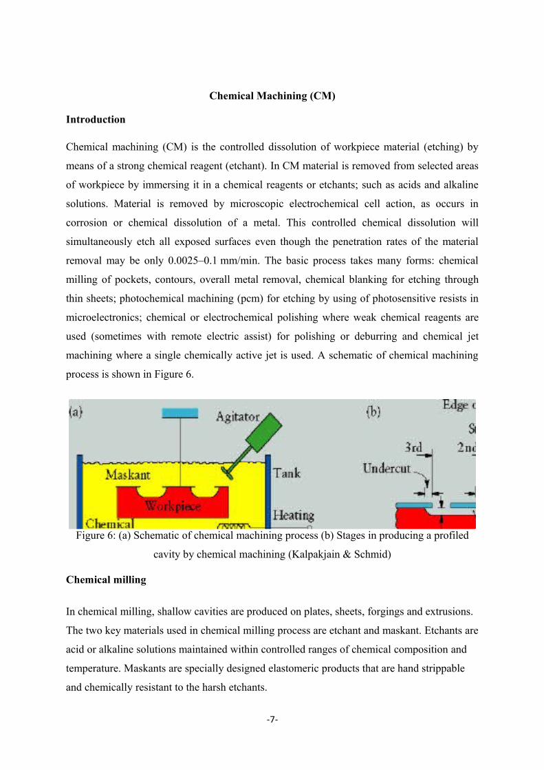
machining where a single chemically active jet is used. A schematic of chemical machining
process is shown in Figure 6.
Figure 6: (a) Schematic of chemical machining process (b) Stages in producing a profiled
cavity by chemical machining (Kalpakjain & Schmid)
Chemical milling
In chemical milling, shallow cavities are produced on plates, sheets, forgings and extrusions.
The two key materials used in chemical milling process are etchant and maskant. Etchants are
acid or alkaline solutions maintained within controlled ranges of chemical composition and
temperature. Maskants are specially designed elastomeric products that are hand strippable
and chemically resistant to the harsh etchants.
-7-
Steps in chemical milling
• Residual stress relieving: If the part to be machined has residual stresses from the
previous processing, these stresses first should be relieved in order to prevent warping
after chemical milling.
• Preparing: The surfaces are degreased and cleaned thoroughly to ensure both good
adhesion of the masking material and the uniform material removal.
• Masking: Masking material is applied (coating or protecting areas not to be etched).
• Etching: The exposed surfaces are machined chemically with etchants.
• Demasking: After machining, the parts should be washed thoroughly to prevent
further reactions with or exposure to any etchant residues. Then the rest of the
masking material is removed and the part is cleaned and inspected.
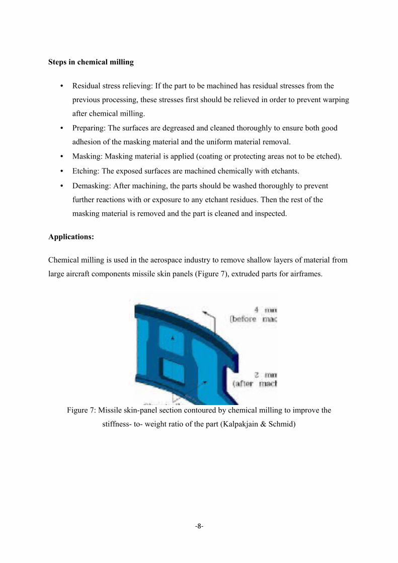
Applications:
Chemical milling is used in the aerospace industry to remove shallow layers of material from
large aircraft components missile skin panels (Figure 7), extruded parts for airframes.
Figure 7: Missile skin-panel section contoured by chemical milling to improve the
stiffness- to- weight ratio of the part (Kalpakjain & Schmid)
-8-
Electrochemical Machining (ECM)
Introduction
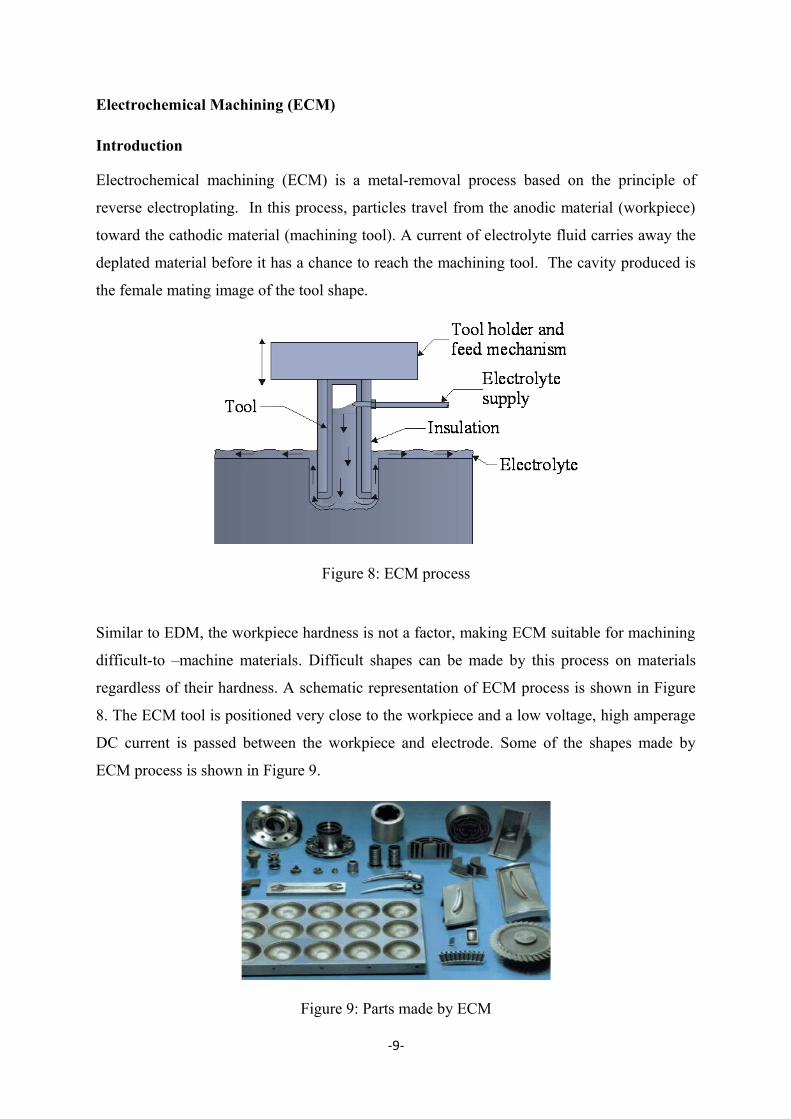
Electrochemical machining (ECM) is a metal-removal process based on the principle of
reverse electroplating. In this process, particles travel from the anodic material (workpiece)
toward the cathodic material (machining tool). A current of electrolyte fluid carries away the
deplated material before it has a chance to reach the machining tool. The cavity produced is
the female mating image of the tool shape.
Figure 8: ECM process
Similar to EDM, the workpiece hardness is not a factor, making ECM suitable for machining
difficult-to –machine materials. Difficult shapes can be made by this process on materials
regardless of their hardness. A schematic representation of ECM process is shown in Figure
8. The ECM tool is positioned very close to the workpiece and a low voltage, high amperage
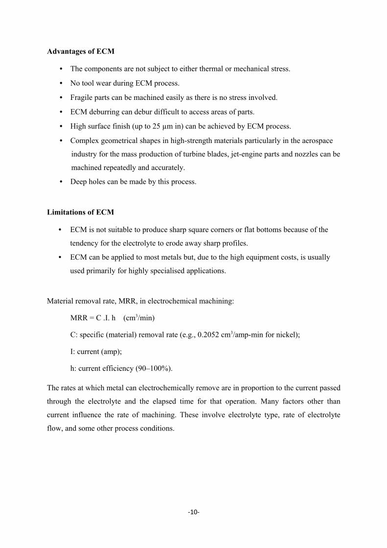
DC current is passed between the workpiece and electrode. Some of the shapes made by
ECM process is shown in Figure 9.
Figure 9: Parts made by ECM
-9-
Advantages of ECM
• The components are not subject to either thermal or mechanical stress.
• No tool wear during ECM process.
• Fragile parts can be machined easily as there is no stress involved.
• ECM deburring can debur difficult to access areas of parts.
• High surface finish (up to 25 µm in) can be achieved by ECM process.
• Complex geometrical shapes in high-strength materials particularly in the aerospace
industry for the mass production of turbine blades, jet-engine parts and nozzles can be
machined repeatedly and accurately.
• Deep holes can be made by this process.
Limitations of ECM
• ECM is not suitable to produce sharp square corners or flat bottoms because of the
tendency for the electrolyte to erode away sharp profiles.
• ECM can be applied to most metals but, due to the high equipment costs, is usually
used primarily for highly specialised applications.
Material removal rate, MRR, in electrochemical machining:
MRR = C .I. h (cm3/min)
C: specific (material) removal rate (e.g., 0.2052 cm3/amp-min for nickel);
I: current (amp);
h: current efficiency (90–100%).
The rates at which metal can electrochemically remove are in proportion to the current passed
through the electrolyte and the elapsed time for that operation. Many factors other than
current influence the rate of machining. These involve electrolyte type, rate of electrolyte
flow, and some other process conditions.
-10-
Ultrasonic Machining (USM)
Introduction
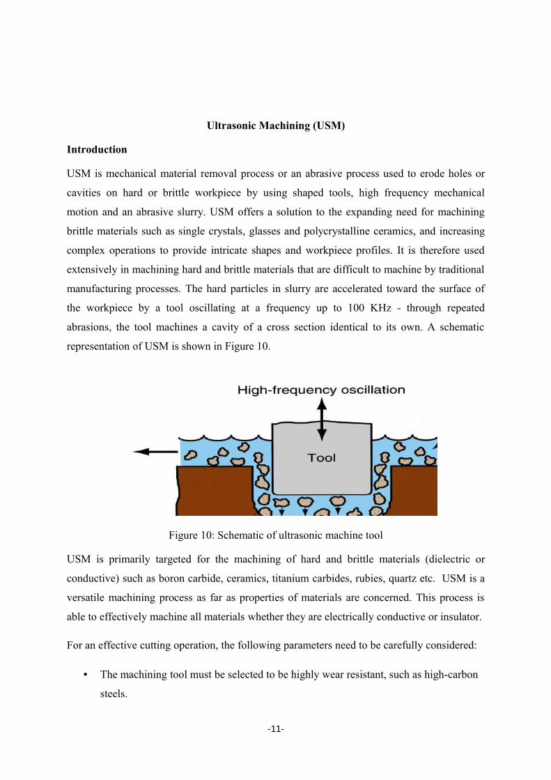
USM is mechanical material removal process or an abrasive process used to erode holes or
cavities on hard or brittle workpiece by using shaped tools, high frequency mechanical
motion and an abrasive slurry. USM offers a solution to the expanding need for machining
brittle materials such as single crystals, glasses and polycrystalline ceramics, and increasing
complex operations to provide intricate shapes and workpiece profiles. It is therefore used
extensively in machining hard and brittle materials that are difficult to machine by traditional
manufacturing processes. The hard particles in slurry are accelerated toward the surface of
the workpiece by a tool oscillating at a frequency up to 100 KHz - through repeated
abrasions, the tool machines a cavity of a cross section identical to its own. A schematic
representation of USM is shown in Figure 10.
Figure 10: Schematic of ultrasonic machine tool
USM is primarily targeted for the machining of hard and brittle materials (dielectric or
conductive) such as boron carbide, ceramics, titanium carbides, rubies, quartz etc. USM is a
versatile machining process as far as properties of materials are concerned. This process is
able to effectively machine all materials whether they are electrically conductive or insulator.
For an effective cutting operation, the following parameters need to be carefully considered:
• The machining tool must be selected to be highly wear resistant, such as high-carbon
steels.
-11-
• The abrasives (25-60 µm in dia.) in the (water-based, up to 40% solid volume) slurry
includes: Boron carbide, silicon carbide and aluminum oxide.
Applications
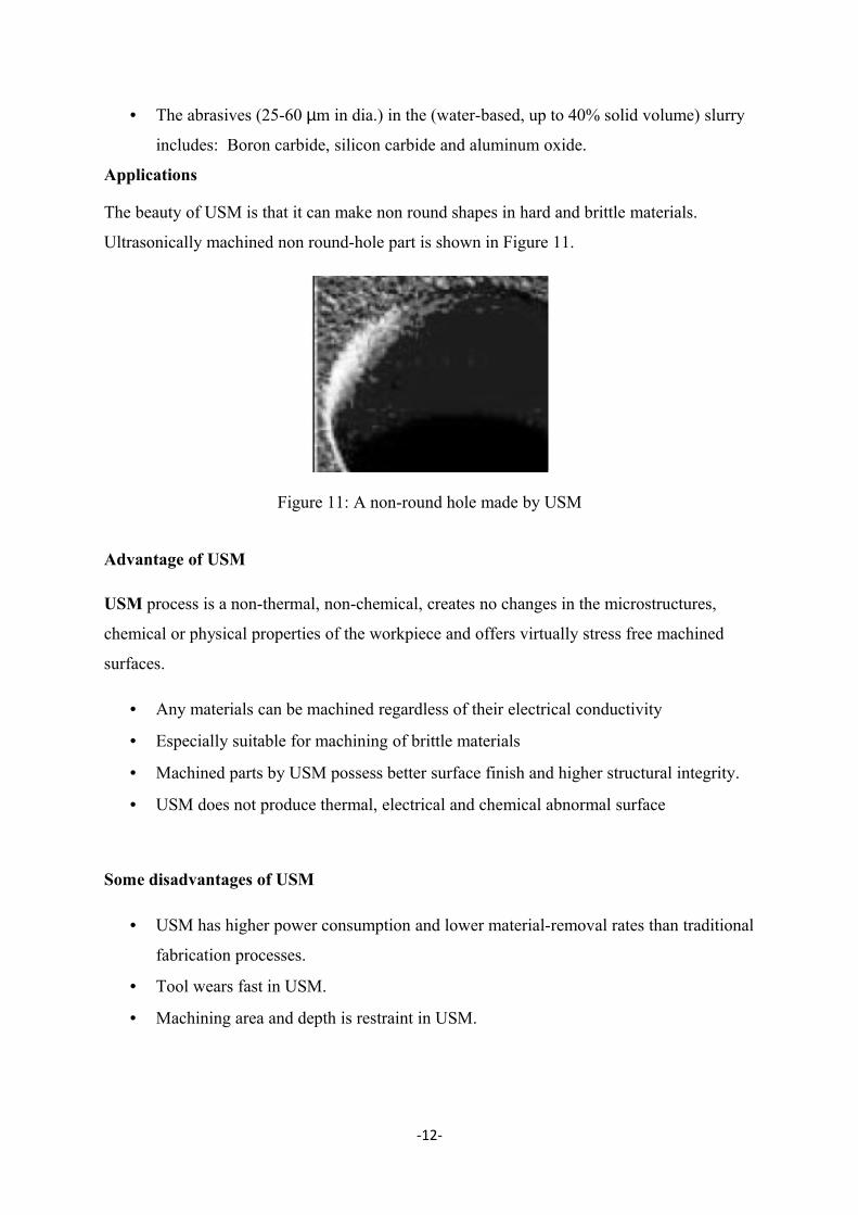
The beauty of USM is that it can make non round shapes in hard and brittle materials.
Ultrasonically machined non round-hole part is shown in Figure 11.
Figure 11: A non-round hole made by USM
Advantage of USM
USM process is a non-thermal, non-chemical, creates no changes in the microstructures,
chemical or physical properties of the workpiece and offers virtually stress free machined
surfaces.
• Any materials can be machined regardless of their electrical conductivity
• Especially suitable for machining of brittle materials
• Machined parts by USM possess better surface finish and higher structural integrity.
• USM does not produce thermal, electrical and chemical abnormal surface
Some disadvantages of USM
• USM has higher power consumption and lower material-removal rates than traditional
fabrication processes.
• Tool wears fast in USM.
• Machining area and depth is restraint in USM.
-12-
Laser–Beam Machining (LBM)
Introduction
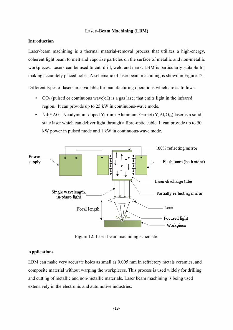
Laser-beam machining is a thermal material-removal process that utilizes a high-energy,
coherent light beam to melt and vaporize particles on the surface of metallic and non-metallic
workpieces. Lasers can be used to cut, drill, weld and mark. LBM is particularly suitable for
making accurately placed holes. A schematic of laser beam machining is shown in Figure 12.
Different types of lasers are available for manufacturing operations which are as follows:
• CO2 (pulsed or continuous wave): It is a gas laser that emits light in the infrared
region. It can provide up to 25 kW in continuous-wave mode.
• Nd:YAG: Neodymium-doped Yttrium-Aluminum-Garnet (Y3Al5O12) laser is a solid-
state laser which can deliver light through a fibre-optic cable. It can provide up to 50
kW power in pulsed mode and 1 kW in continuous-wave mode.
Figure 12: Laser beam machining schematic
Applications
LBM can make very accurate holes as small as 0.005 mm in refractory metals ceramics, and
composite material without warping the workpieces. This process is used widely for drilling
and cutting of metallic and non-metallic materials. Laser beam machining is being used
extensively in the electronic and automotive industries.
-13-
Laser beam cutting (drilling)
• In drilling, energy transferred (e.g., via a Nd:YAG laser) into the workpiece melts the
material at the point of contact, which subsequently changes into a plasma and leaves
the region.
• A gas jet (typically, oxygen) can further facilitate this phase transformation and
departure of material removed.
• Laser drilling should be targeted for hard materials and hole geometries that are
difficult to achieve with other methods.
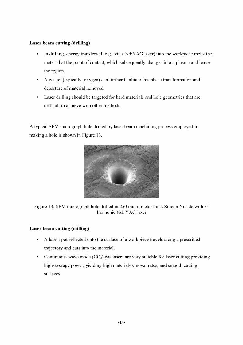
A typical SEM micrograph hole drilled by laser beam machining process employed in
making a hole is shown in Figure 13.
Figure 13: SEM micrograph hole drilled in 250 micro meter thick Silicon Nitride with 3rd
harmonic Nd: YAG laser
Laser beam cutting (milling)
• A laser spot reflected onto the surface of a workpiece travels along a prescribed
trajectory and cuts into the material.
• Continuous-wave mode (CO2) gas lasers are very suitable for laser cutting providing
high-average power, yielding high material-removal rates, and smooth cutting
surfaces.
-14-
Advantage of laser cutting
• No limit to cutting path as the laser point can move any path.
• The process is stress less allowing very fragile materials to be laser cut without any
support.
• Very hard and abrasive material can be cut.
• Sticky materials are also can be cut by this process.
• It is a cost effective and flexible process.
• High accuracy parts can be machined.
• No cutting lubricants required
• No tool wear
• Narrow heat effected zone
Limitations of laser cutting
• Uneconomic on high volumes compared to stamping
• Limitations on thickness due to taper
• High capital cost
• High maintenance cost
• Assist or cover gas required
-15-
Water Jet Cutting
Introduction
Water jet cutting can reduce the costs and speed up the processes by eliminating or reducing
expensive secondary machining process. Since no heat is applied on the materials, cut edges
are clean with minimal burr. Problems such as cracked edge defects, crystalisation,
hardening, reduced wealdability and machinability are reduced in this process.
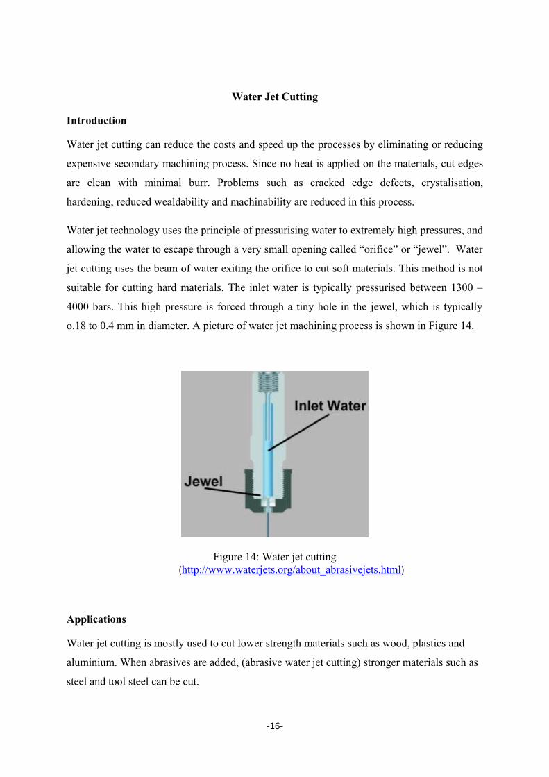
Water jet technology uses the principle of pressurising water to extremely high pressures, and
allowing the water to escape through a very small opening called “orifice” or “jewel”. Water
jet cutting uses the beam of water exiting the orifice to cut soft materials. This method is not
suitable for cutting hard materials. The inlet water is typically pressurised between 1300 –
4000 bars. This high pressure is forced through a tiny hole in the jewel, which is typically
o.18 to 0.4 mm in diameter. A picture of water jet machining process is shown in Figure 14.
Figure 14: Water jet cutting(http://www.waterjets.org/about_abrasivejets.html)
Applications
Water jet cutting is mostly used to cut lower strength materials such as wood, plastics and
aluminium. When abrasives are added, (abrasive water jet cutting) stronger materials such as
steel and tool steel can be cut.
-16-
Advantages of water jet cutting
• There is no heat generated in water jet cutting; which is especially useful for cutting
tool steel and other metals where excessive heat may change the properties of the
material.
• Unlike machining or grinding, water jet cutting does not produce any dust or particles
that are harmful if inhaled.
• Other advantages are similar to abrasive water jet cutting
Disadvantages of water jet cutting
• One of the main disadvantages of water jet cutting is that a limited number of
materials can be cut economically.
• Thick parts cannot be cut by this process economically and accurately
• Taper is also a problem with water jet cutting in very thick materials. Taper is when
the jet exits the part at different angle than it enters the part, and cause dimensional
inaccuracy.
-17-
Abrasive Water-Jet Cutting
Introduction
Abrasive water jet cutting is an extended version of water jet cutting; in which the water jet
contains abrasive particles such as silicon carbide or aluminium oxide in order to increase the
material removal rate above that of water jet machining. Almost any type of material ranging
from hard brittle materials such as ceramics, metals and glass to extremely soft materials such
as foam and rubbers can be cut by abrasive water jet cutting. The narrow cutting stream and
computer controlled movement enables this process to produce parts accurately and
efficiently. This machining process is especially ideal for cutting materials that cannot be cut
by laser or thermal cut. Metallic, non-metallic and advanced composite materials of various
thicknesses can be cut by this process. This process is particularly suitable for heat sensitive
materials that cannot be machined by processes that produce heat while machining.
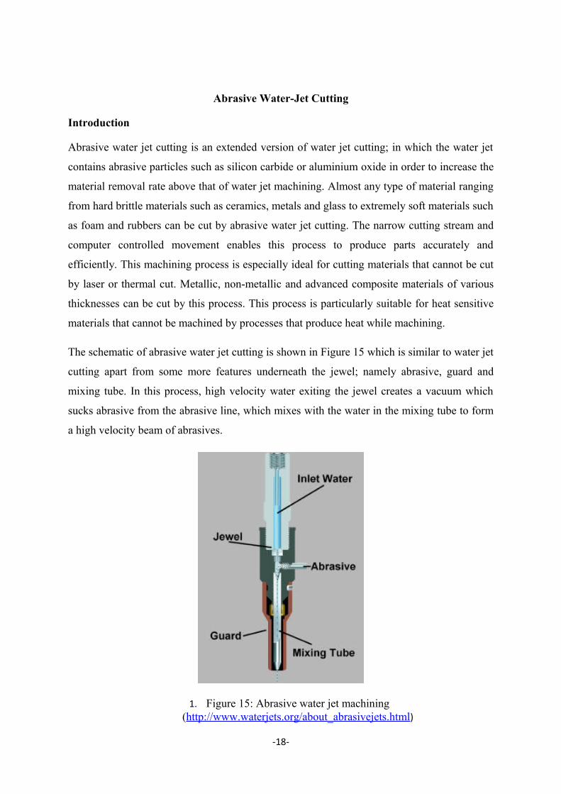
The schematic of abrasive water jet cutting is shown in Figure 15 which is similar to water jet
cutting apart from some more features underneath the jewel; namely abrasive, guard and
mixing tube. In this process, high velocity water exiting the jewel creates a vacuum which
sucks abrasive from the abrasive line, which mixes with the water in the mixing tube to form
a high velocity beam of abrasives.
1. Figure 15: Abrasive water jet machining (http://www.waterjets.org/about_abrasivejets.html)
-18-
Applications
Abrasive water jet cutting is highly used in aerospace, automotive and electronics industries.
In aerospace industries, parts such as titanium bodies for military aircrafts, engine
components (aluminium, titanium, heat resistant alloys), aluminium body parts and interior
cabin parts are made using abrasive water jet cutting.
In automotive industries, parts like interior trim (head liners, trunk liners, door panels) and
fibre glass body components and bumpers are made by this process. Similarly, in electronics
industries, circuit boards and cable stripping are made by abrasive water jet cutting.
Advantages of abrasive water jet cutting
• In most of the cases, no secondary finishing required
• No cutter induced distortion
• Low cutting forces on workpieces
• Limited tooling requirements
• Little to no cutting burr
• Typical finish 125-250 microns
• Smaller kerf size reduces material wastages
• No heat affected zone
• Localises structural changes
• No cutter induced metal contamination
• Eliminates thermal distortion
• No slag or cutting dross
• Precise, multi plane cutting of contours, shapes, and bevels of any angle.
Limitations of abrasive water jet cutting
• Cannot drill flat bottom
• Cannot cut materials that degrades quickly with moisture
-19-
• Surface finish degrades at higher cut speeds which are frequently used for rough
cutting.
• The major disadvantages of abrasive water jet cutting are high capital cost and high
noise levels during operation.
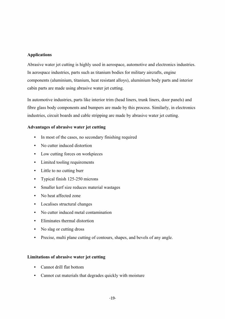
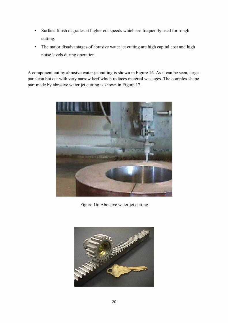
A component cut by abrasive water jet cutting is shown in Figure 16. As it can be seen, large parts can but cut with very narrow kerf which reduces material wastages. The complex shape part made by abrasive water jet cutting is shown in Figure 17.
Figure 16: Abrasive water jet cutting
-20-

Figure 17: Steel gear and rack cut with an abrasive water jet
-21-
References
2. Manufacturing Engineering and Technology Fifth Edition - Serope Kalpakjian and
Steven R Sschmid. (Prentice Hall), 2006.
3. Manufacturing Technology, Volume 2. R L Timings & S P Wilkinson (Longman)
2000.
4. Manufacturing Processes and Equipment – George Tlusty (Prentice Hall).
5. E. Paul DeGarmo, J.T. Black, R.A. Kohsern, Materials and Processes in
Manufacturing, 8th ed., Prentice-Hall, Englewood Cliffs, NJ, 1997, pp. 941–947.
6. Chemical Machining, Metals Handbook, vol. 3, Machining, 8th ed., American Society
for Metals, Metals Park, OH, pp. 240–248.
7. http://www.dimeg.unipd.it/didattica/31/8_Non_conventional.pdf
8. www.eng.morgan.edu
9. http://www.answers.com/topic/electrical-discharge-machining
10. http://www.exitech.co.uk/pdfFiles/Microhole%20Drilling%20using%20Reshaped %20Pulsed%20Gaussian%20Laser%20Beam.pdf
11. http://www.google.co.uk/search? q=ultrasonic+machining+picture&hl=en&start=10&sa=N
12. http://www.ebtecwelding.com/waterjet-cutting/wjetlimitations.html
13. http://www.waterjets.org/about_abrasivejets.html
14. http://www.waterjets.org/index.html
-22-