manufacturing processes dr. apiwat muttamara. metal cutting 1.traditional machine turning milling...
TRANSCRIPT

Manufacturing Processes
• Dr. Apiwat Muttamara
Metal Cutting
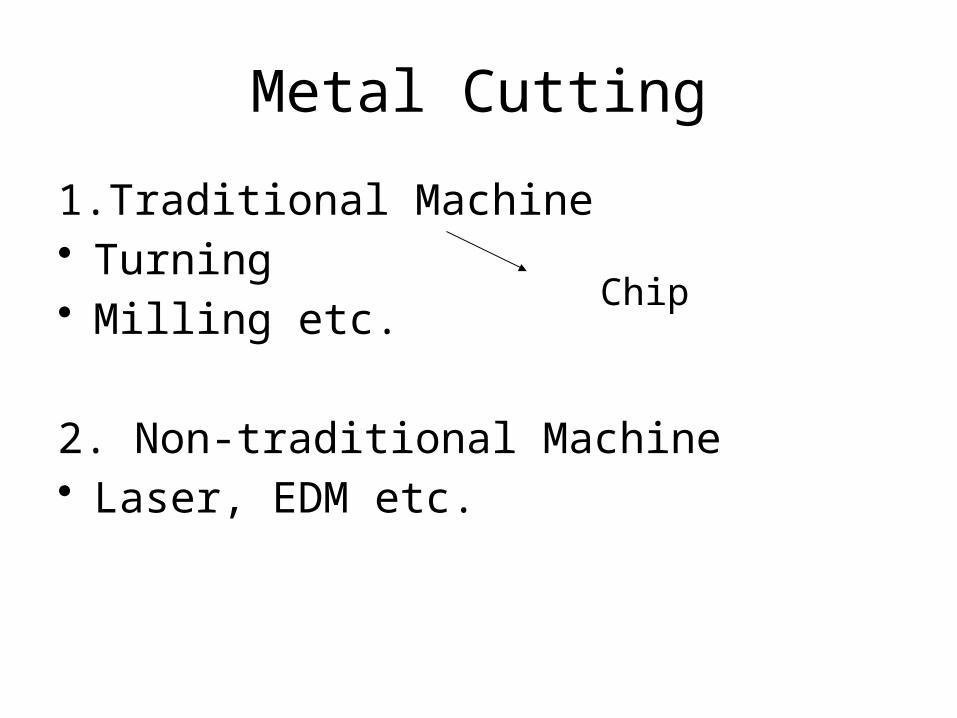
1.Traditional Machine• Turning• Milling etc.
2. Non-traditional Machine• Laser, EDM etc.
Chip

Turning

Propose
• The operational uses and parameters, • The general layout of controls, accessories,
associated tooling• It takes a considerable time to become a skilled
lathe operator and to possess all the skill of hand that goes with it. Therefore it is not expected that you will be manually skilled on completion of the module but you will have gained intellectually, by practical involvement, some skill of hand will be achieved.

Centre Lathe
apron

Bed
- the main frame,H-beam on 2 V-support– It has guideways for carriage to slide easily
lengthwise
Headstock– The spindle is driven through the gearbox
Tailstock
- Quill- Lath center, Tooling reference- Drill

Quill
TailstockChuck
A Plain Lath Center

Producing a Cylindrical Surface
Producing a Flat Surface

• Figure 2e. Radius Turning Attachment
Figure 2c. Taper Turning

Cutting Tools


Bevel gear with spiral scroll
Bevel pinion
CHUCKJAW

Face PlateCounterweght
Workpiece

Face plate
Dog
Workpiece
Lathe Center

Steady rest
Three Adjustable Jaws
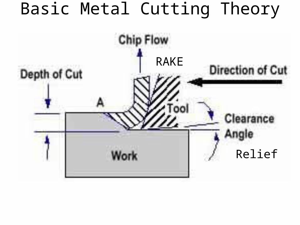
Basic Metal Cutting Theory
Relief
RAKE

Main Features of a Single Point Cutting Tool

Rake Angle • The larger the rake angle, the smaller the
cutting force on the tool, • A large rake angle will improve cutting action,
but would lead to early tool failure• A compromise must therefore be made
between adequate strength and good cutting action.
Clearance AngleClearance should be kept to a minimum, as excessive clearance angle will not improve cutting efficiency and will merely weaken the tool.

Characteristics of Tool Material
• Hot Hardness – the ability to retain its hardness at high
temperatures. • Strength and Resistance to Shock
– At the start of a cut the first bite of the tool into the work results in considerable shock
• Low Coefficient of Friction

Tool Materials in Common Use• High Carbon Steel
• Contains 1 - 1.4% carbon with some addition of chromium and tungsten to improve wear resistance.
• The steel begins to lose its hardness at about 250° C, and is not favoured for modern machining operations where high speeds and heavy cuts are usually employed.
• High Speed Steel (H.S.S.) • Steel, which has a hot hardness value of about 600° C, • commonly used for single point and multi point cutting tools
• Cemented Carbides (WC-Co)• An extremely hard material made from tungsten powder. • Carbide tools are usually used in the form of brazed or clamped tips• HSS may be readily machined using carbide tipped tool.• High cutting speeds may be used and materials difficult to cut with HSS

Blade material and major usesCarbon steel, steel alloy Slow cutting
High-speed steel General cutting, difficult-to-cut material
Coated super-hard alloys General cutting
Ceramics High-speed cutting finishing cuts
Polycrystalline Diamond Non-ferrous alloy, non-metal material cutting
Sintered cubic boron nitride (CBN)
Super-hard alloy, quenched steel, finish cut

Coating Materials for Cutting tool
PCD Polycrystalline Diamond
CBN Cubic Boron Nitride
WC-Co
TiC or TiN or TiCN,
Al2O3


CERMETCeramic+metal

material & cutting conditions These conditions include the type of tool used tool, rate of cutting condition of the machine and the use or absence of a cutting fluid.
Chip Formation & Chip Breaker

- The chip leaves tools a long ribbon -common when cutting most ductile materials such as mild steel, copper and Aluminium.
Ideal ChipIt is associated with good tool angles, correct speeds and feeds, and the use of cutting fluid.
Continuous Chip

Discontinuous Chip
-resulted from cutting brittle metals such as cast iron and cast brass with tools having small rake angles.
There is nothing wrong with this type of chip in these circumstances

Continuous Chip with Builtup Edge (BUE)
This is a chip to be avoided and is caused by small particles from the workpiece becoming welded to the tool face under high pressure and heat. The phenomenon results in a poor finish and damage to the tool.
It can be minimised or prevented by using light cuts at higher speeds with an appropriate cutting lubricant

Cutting Speed
• • Where:
N = Spindle Speed (RPM)CS = Cutting Speed of Metal (m/min)d = Diameter of Workpiece
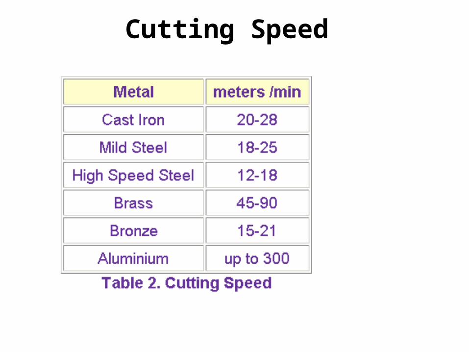
Cutting Speed

Feed
• The term `feed' is used to describe the distance the tool moves per revolution of the workpiece and depends largely on the surface finish required. For roughing out a soft material a feed
of up to 0.25 mm per revolution may be used. With tougher materials this should be reduced to
a maximum of 0.10 mm/rev. Finishing requires a finer feed then what is recommended.

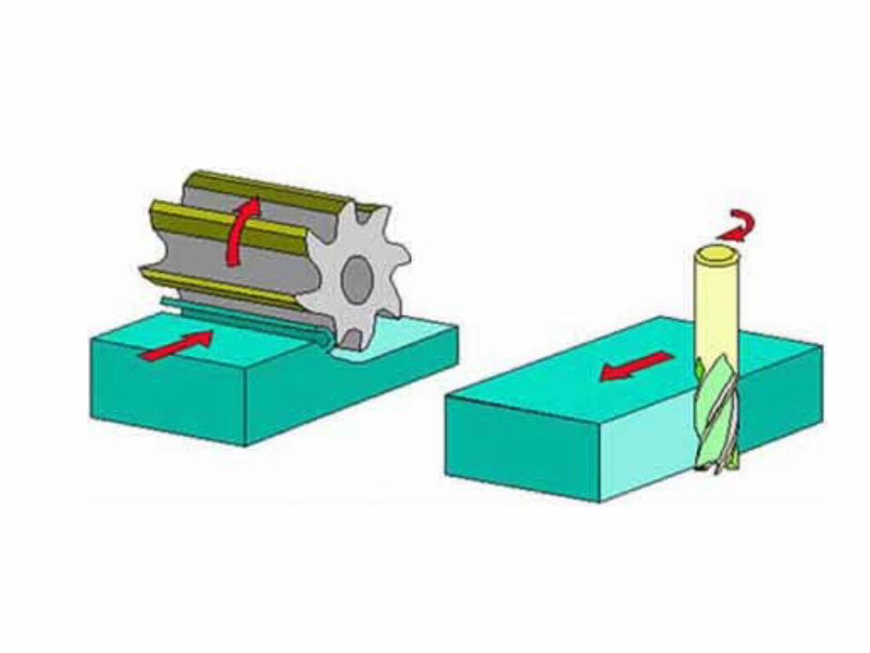
Milling

Types of Milling Machine
• Horizontal Vertical

Slab MillsFor heavy cutting of large and flat surfaces
Side and Face Cutters
Slitting Saw

End mill
• Cutting tools for Vertical Milling a. End Mills
Rough Cut End MillsFor rapid metal removal.
• End Mill

Slot Drill
Face Milling Cutters

INSERT ENDMILL
• INSERT ENDMILL
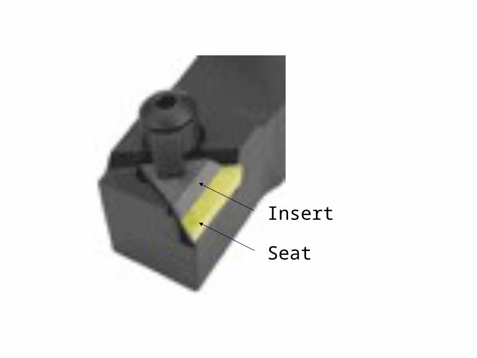
Seat
Insert

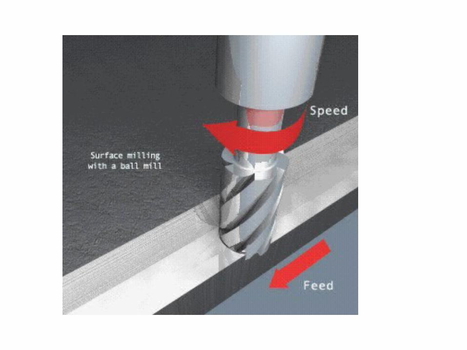
Ballnose

Spindle Speed
• Spindle speed in (R.P.M.)
where -- N = R.P.M. of the cutterCS = Linear Cutting Speed of the material in m/min. ( see table 1 ) d = Diameter of cutter in mm

Feed Rate
• Feed rate (F) is defined as the rate of travel of the workpiece in mm/min.
• where -- F = table feed in mm/min f = movement per tooth of cutter in mm ( see table 1 ) u = number of teeth of cutter N = R.P.M. of the cutter
•F = f . u . N

Table 1
•F = f . u . N

Depth of Cut
• Depth of cut is directly related to the efficiency of the cutting process.
• For a certain type of cutter, a typical range of cut will be recommended by the supplier.

Down Cut,Climb MillingUp Cut• direction opposite to the
table. • conventional milling
Feed Direction
• Backlash• CNC milling machine. • Require less power in feeding the table • Give a better surface finish on the
workpiece.


T-SlotForming cutting
tool

Gear Cutting
INDEXING HEAD

Milling Processes

Cutting fluid (Coolant)
1. Reduce the temp.
2. Reduce friction.
3. Wash away chips
4. Improve surface finish
5. Increase tool life
6. Help prevent BUE
Functions;

Cutting fluids in common use • Water • encourages rusting
• Soluble Oils • Adding emulsifying agents. • These fluids have average lubricating abilities and good cooling
properties. • There are many forms of soluble oil in the market and the suppliers
instruction should be followed regarding the proportions of the `mix'.
• Mineral Oils • They are used for heavier cutting operations • Mineral oils are very suitable for steels but should not be used on
copper or its alloys since it has a corrosive effect
• Vegetable Oils• They are good lubricants but are of little used since they are liable to
decompose and smell badly.

Work Holding Method
vice

The accuracy of dial 0.010 mm.
It is usually used for calibration of machine.
Dial gauge


Tools• Twist Drill:
–Shank–Body–Point

Center Drill
Prick Before drill

COUNTERSINK&BORE

Collet

ColletTightening Nut

Shank
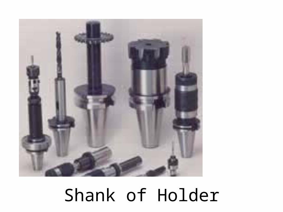
Shank of Holder

TAP
Inside Thread

DIE
Outside Thread

Reamer
Functions of reamer are to control the diameter of a hole to improve the internal surface finish to improve the roundness of the hole

12
Drill 12.00mm Hole 11.75 + 0.10 mm
Ream 12.00mm Hole 12.00 + 0.18 mm - 0.00
- 0.10