non-linear mechanical analysis of the composite
TRANSCRIPT

ADVANCES IN MANUFACTURING SCIENCE AND TECHNOLOGY Vol. 37, No. 4, 2013
DOI: 10.2478/amst-2013-0030
Address: Tomasz NOWAK, ABB Corporate Research, Cracow, Poland, Starowiślna 13A, 31-038 Kraków, e-mail: [email protected], Jerzy SCHMIDT, Cracow University of Technology, Poland, Jana Pawła II, 31-864 Kraków, e-mail: [email protected]
NON-LINEAR MECHANICAL ANALYSIS OF THE COMPOSITE OVERWRAPPED CYLINDER
FOR HYDRAULIC APPLICATIONS
Tomasz Nowak, Jerzy Schmidt
S u m m a r y
This paper provides a new method for an elasto-plastic analysis of stress and deformation fields in the composite overwrapped cylinder under the pressure load. The cylinder structure consisting of steel liner and composite shell was examined. The non-linear properties of the steel tube, and orthotropic properties of the composite were assumed in this analysis. The compound cylinder was checked against internal working pressure and external axial forces. The optimal design parameters of the pressurized vessel were found by analytical as well as numerical methods, and later validated in experimental measurements. It was generally found, that composite reinforcement does not contribute very much to the mechanical performance of the cylinder when the steel liner works in elastic range, but, in contrast, it provides a big support when the metal tube approaches plastic deformation. This phenomenon allows to increase the power-to-weight ratio of the pressurized vessel, what is especially important for demanding hydraulic applications
Keywords: pressure vessels, composite-reinforced metal cylinders, elasto-plastic analysis
Nieliniowa analiza wytężenia cylindrów hydraulicznych wzmacnianych kompozytem
polimerowym
S t r e s z c z e n i e
W pracy przedstawiono metodę analizy mechanicznej cylindra hydraulicznego wzmocnionego płaszczem kompozytowym. Cylinder poddano obciążeniu roboczemu wywołującemu odkształcenie sprężysto-plastyczne. W analizie uwzględniono nieliniową zależność naprężenie-odkształcenie dla tulei metalowej, natomiast dla kompozytu polimerowego założono ortotropię jego właściwości. Obciążenie robocze powoduje zarówno ciśnienie działające na wewnętrze ścianki cylindra, jak i zewnętrzna siła osiowa. Zaproponowano nową, analityczną metodę obliczeniową. Stanowi ona podstawę do opty-malizowania konstrukcji cylindra: doboru materiału kompozytowego, orientacji poszczególnych warstw oraz ich grubości. Prowadzono zarówno weryfikację numeryczną metodą elementów skończonych, jak i laboratoryjną poprzez realizację opracowanego programu badań. Analiza uzyskanych wyników pozwala stwierdzić, że wzmocnienie kompozytowe nie jest znacznie obciążone, dopóki stalowa tuleja pracuje w zakresie sprężystym odkształcenia. Zwiększenie obciążenia roboczego powoduje, że naprężenie jest większe od granicy sprężystości metalu. Zwiększa się również odkształcenie plastyczne. Wówczas znaczną część obciążenia przejmuje płaszcz kompozytowy. Zjawisko to jest korzystne – umożliwia lepsze wykorzystanie materiału cylindra i jednocześnie zabezpiecza tuleję stalową przed nadmiernym obciążeniem.
Słowa kluczowe: zbiorniki ciśnieniowe, tuleje wzmocnione powłoką kompozytową, analiza.

32 T. Nowak, J. Schmidt
1. Introduction
Composite structures are frequently used in many branches of the industry because of their good mechanical properties and low weight. These benefits are of great importance in applications, where size or weight limits play a significant role. It is especially the case for hydraulic actuators that must be manually handled by operators. In such a situation an every additional kilogram of weight contributes directly to the reduction of equipment’s mobility.
In general, the hydraulic cylinders and vessels under high pressure require a strict analysis for an optimum design for reliable and secure operation performance. Over last decades efforts were continually made to increase the reliability of steel structures and power-per-weight ratio. Solutions have been obtained either in the analytical form, or with numerical implementations. The literature includes methods proposed by Hill [1], Mendeleson [2], Chakrabarty [3], Fryer and Harvey [4] - to name just a few of them. Durban and Kubi [5] first, and Parker [6] later suggested an analytical solution for solving pressurized elastic-plastic tubes in plane state. In 2003 Zhao and co-workers [7], as well as Perry and Aboundi [8] offered numerical procedures for solution of thick-walled elastic-plastic tubes using total deformation theory of plasticity. Lately, Widlak [9] provided the novel approach for elasto-plastic analysis of steel tubes using FEM procedures.
As filament-wound tubes made of fiber-reinforced composites have many potential advantages over cylinders made of the conventional steel, a number of researchers have investigated their applications and failure mechanisms [10-12]. For thin-walled pressure vessels with the ration of applied hoop-to-axial stress of two to one, an optimum winding angle of 55˚ was noted, and many experimental failure analyses were conducted [13-15]. Uemura and Fukunaga [16] and Lifshitz and Dayon [17] have investigated, respectively, the failure mechanism in carbon fiber-reinforced plastics (CFRP) and glass fiber-reinforced plastics (GFRP) tubes wound at different angles, and they generally confirmed the earlier studies. Similarly Czarnocki [18] studied fracture toughness of glass/epoxy and carbon/epoxy laminates using methods based on the energy principles. Wild and Vickers [19] have developed an analytical procedure based on the theory of orthotropic cylindrical sheets and modeled both: plane-stress and plane-strain states of cylinder comprising a number of sublayers, which are cylindrically orthotropic.
Most of the studies managed so far have focused on pressurized steel tubes or fiber-reinforced composite cylinders, while very limited studies have been published on multi-layer, metal-composite structures. Especially the interaction between composite’s reinforcement and the metal tube working in the plastic
Non-linear mechanical analysis ... 33
regime was not covered in details. The work described in this paper is focused on developing and analysis of a new type of metal-composite structure, aiming to form the high-pressure hydraulic cylinders. The composite overwrapped steel cylinders exposed to internal pressure and axial load have been designed, evaluated analytically, produced and exposed to the experimental measurements. The proposed calculation technique uses piecewise linear approximation of the actual stress-strain relation of the steel part, and classical laminated-plate theory to describe the elastic behavior of the overwrapping shell. The analyzed structure, in which the steel tube was reinforced by the composite shell, exhibited superior mechanical performance, what manifested in much higher strength and power-per-weight ratio. In addition, the AE technique has been applied to describe the failure mechanism of the composite under study, and pattern recognition method helped to identify groups of signals responsible for various failure modes. The results of performed numerical and experimental work explained the mechanism of stress distribution within the composite reinforced steel cylinder, and allowed to design the lightweight hydraulic device.
The paper is formatted as follows: section 2 presents the analytical calculation model for metal-composite structure, while next chapter gives preliminary dimensioning calculations of the cylinder’s liner structure – the thickness of each layer. The proposed dimensions of the cylinder were successively verified by Finite Element Analysis. Chapter 3 covers the results of analytical as well as numerical calculations. In Section 4 the laboratory work is presented shortly, while the concluding remarks are gathered in the last paragraph of the work.
2. Analytical calculation model
2.1. Calculation procedure
In order to solve the problem analytically, the following assumptions were applied:
• the object under study is constructed out of two, co-axial cylindrical parts, made of different materials, as shown schematically in Fig. 1.:
− the inner part, marked as „1”, represents the metal skeleton (having the thickness e1),
− the outer part, marked as „2”, symbolizes the composite shell (having the total thickness e2),
• the composite shell, consists of several layers of carbon (or basalt) fibers oriented at different helical angles, and embodied in epoxy resin matrix,
• the orientation and the number of fiber layers are unrestricted, but should form the symmetrical structure (e.g. +55º / -55º), and the entire thickness of all layers constitutes the outer part (Σti=e2),

34 T. Nowak, J. Schmidt
• steel part of the cylinder (inner tube) the non-linear material properties, for are assumed while for the composite cylinder (outer tube) – linear-elastic model is used,
• both tubes: steel and composite are perfectly bounded, • because the total thickness of the structure is low with respect to the
cylinder radius, r/e > 15, (not scaled in Fig. 1) the theory of thin-wall shells can be applied,
• equivalent properties of the composite were calculated based on the rule of mixture and classical composite laminates,
• for elasto-plastic behavior of the steel the quasi-elastic approach, with piecewise approximation of the strain-stress curve, is used.
Fig. 1. Geometrical model of the cylinder under study (scale not kept)
The systematic analysis of the problem requires the determination of equilibrium relations, as well as constitutive equations for the double-layer cylinder, assuming some equivalent mechanical modules. These correspondent properties of the composite should be specified with respect to the properties of an individual plies (their thickness and orientation angles), while properties of the steel tube should incorporate the non-linear stress-strain relation. Finally, the optimal design dimensions can be found, allowing for weight-saving and ensuring the reliable operation of the product.
To determine the stress and strain fields in both: the steel frame and the composite shell, one can apply equilibrium and constitutive equations. On the basis of the first relation (Fig. 2), it is possible to state:

Non-linear mechanical analysis ... 35
( )( )
1 1 2 2 0
21 1 2 2 0
1 2 1 2
2
X X
Y Y
e e r p
r e e r p F
σ σ
π σ σ π
× + = × ×
+ = − (1)
a) b)
Fig. 2. Equilibrium relations for axial and hoop directions: a) axial direction, b) hoop direction
It must be noted that: • the radius r refers to the mid-plane radius. For the sake of simplicity it
was assumed, that it is the radius of the interface (contact) plane between steel and composite tubes,
• force F represents the external axial load applied to the cylinder, and ranges from 0 (when the cylinder is not supported) to the Fmax value = πr2p0 (when the cylinder is fully loaded). It is worth noting that in the case of external Fmax axial load, only hoop stresses exist within the cylinder’s walls – the axial stresses vanish, and it is a case, that generates the highest stress intensity value (vonMises stress).
The simplification of the equilibrium relations drives to:
1 1 2 2 0
1 1 2 2 02 2
X X
Y Y
e e p r
r Fe e p
r
σ σ
σ σπ
+ = + = −
(2)
The constitutive equations must be written for steel tube and composite tube independently, with respective indices “1” and “2”:

36 T. Nowak, J. Schmidt
1 1 1 1 1
1 1 1 1 1
1 1 1
1/ / 0
/ 1 / 0
/ 2 0 0 1/ 2
X X
Y Y
XY XY
E E
E E
G
ε ν σε ν σ
γ τ
− = −
(3)
2 2
2 2
2 2
1/ / 0
/ 1/ 0
/ 2 0 0 1/ 2
X X YX Y X
Y XY X Y Y
XY XY XY
E E
E E
G
ε ν σε ν σ
γ τ
− = −
(4)
Please note, that “dash” sign in eq. (4) points out that there are equivalent properties used for composite, since it consists of several different plies.
Fulfilling the statement that steel and composite tubes are bounded, one should also assume that their strains in respective directions (axial and radial) are equal, to each other:
1 2
1 2
X X
Y Y
ε εε ε
==
(5)
The remaining condition on equality of the shear strain, γ, can be omitted, since it is automatically satisfied in the case of composite having plies oriented symmetrically (+45°/–45°).
Then, equations (3) and (4) form the following system:
11 1 2 2
1 1
11 1 2 2
1 1
1 1
1 1
YXX Y X Y
X Y
XYX Y X Y
X Y
E E E E
E E E E
ν νσ σ σ σ
ν νσ σ σ σ
− = −− + = − +
(6)
Relations (2) and (6) constitute a system of four equations with the same number of unknowns (σ1X, σ1Y, σ2X, σ2Y), which can be easily derived:
1 20
11 20
11
21 1
1 2
1 1
0 0
0 0
1 12 2
01 1
0
X
YYX
XX Y
XY Y
X Y
e ep r
e ep r F
rE E E E
E E E E
σσν ν
πσν ν σ
− =− −
− −
(7)
Non-linear mechanical analysis ... 37
In order to determine the effective stress, which is a scalar measure of stress intensity, von Mises criterion can be used:
( )22 21
2Mises X Y X Yσ σ σ σ σ= + + − (8)
As a next step, the equivalent properties of the composite tube, and elasto-plastic properties of the steel tube must be estimated.
2.2. Equivalent material properties for the composite
In order to provide equivalent material properties for the multi-layer composite structure having different orientation of fibers (e.g. +45º / 0º /–45º), one must note that each ply is formed as a mixture of roving and resin matrix. Thus, the concept of the commonly used rule of mixtures may be involved to derive properties of a single ply:
(1 )
(1 )
(1 )
(1 )
L f m
m fT
m f
LT f m
TTL LT
L
m fLT
m f
E fE f E
E EE
fE f E
f f
E
E
G GG
fG f G
ν ν ν
ν ν
= + −
=+ −
= + −
=
=+ −
(9)
where: f is a fiber volume fraction (typically about 0.6), and indices m and f refer to matrix and fiber, respectively. EL and ET represent Young Modulus for the ply in longitudinal and transverse directions, correspondingly. G and ν with respective indices are Kirchhoff modulus and Poisson ratio.
The mechanical properties, as given by (9), form local stiffness matrix, [ki], which is oriented along the roving fibers (according to the local co-ordinate system):

38 T. Nowak, J. Schmidt
[ ]
01 1
01 1
0 0 2
L LT T
LT TL LT TL
TL L Ti
LT TL LT TL
LT
E E
E Ek
G
νν ν ν ν
νν ν ν ν
− −
=− −
(10)
Since the longitudinal direction of a single i-th ply may be arbitrarily oriented in global co-ordinate system (in most cases its Z-axis is rotated about the helical angle, α), therefore it is also needed to transform the local stiffness matrix into the global one, [K]:
[ ] [ ] 1i iK T k T−= (11)
where [Ki] is the stiffness matrix in global co-ordinate system, and T – is the rotation matrix, given as below:
2 2
2 2
2 2
2
2
c s sc
T s c sc
sc sc c s
= − − −
(12)
where: s – sinα, c – cosα; α – rotation angle about Z axis in GCS.
If the composite consists of several plies, than the global properties [KG] for the whole structure are derived based on the thickness of individual plies:
[ ] [ ]1 N
G i ii
K t Kt
= ∑ (13)
where: ti – thickness of i-th ply, t – total thickness of all, N plies.
Next, based on equations (4) and (13) one can write:
[ ]2 2
12 2
2 2
X X
Y G Y
XY XY
K
ε σε σγ τ
− =
(14)

Non-linear mechanical analysis ... 39
Thus, in order to determine equivalent mechanical properties of the multi-layer composite, it is necessary to calculate the inverse of the global stiffness matrix, [KG]-1 first, and perform simple operations on its components:
[ ]33
2221
1211
1
00
0
0
G
GG
GG
G
k
kk
kk
K =−�
11
22
21
11
12
22
33
1
1
1
2
XG
YG
GXY
G
GYX
G
XYG
Ek
Ek
k
k
k
k
Gk
ν
ν
= = = −
= −
=
(15)
Finally, it is worth noting that (local) stresses in individual layers of the composite structure can be determined as:
[ ] [ ]2
112
L X
T i G Y
LT XY
k T K
σ σσ σγ γ
−− =
(16)
2.3. Equivalent elastic-plastic properties of the steel
The set of equations (7) holds if the material works in elastic regime. When, under the effect of pressure load, a steel cylinder is plasticized, and its mechanical properties are subject to change. However, using the quasi-elastic approach, proposed by A. Iliuszyn in in the mid-40's of the twentieth century, one can assume that equation (7) still holds, since the metal properties are expressed in their equivalent form. Young Modulus, E1, which is replaced by its secant value E’, and respective Poisson ratio ν’ should be calculated as follows:
( )
'
1 '' 1 1 2
2
Mises
MisesPL
E
EE
E
σσ ε
υ υ
=+
= − −
(17)
40 T. Nowak, J. Schmidt
where: E and ν are material properties in elastic range, while relation between true stress (σMises) and plastic strain (εPL) may be found during standard measurements of the tensile test for the particular steel material.
One may note that equivalent Young modulus E’ in (17) is calculated with respect to the total value of strain (elastic and plastic), thus the applied quasi-elastic approach is reasonable and gives proper results. Because, in the modified system of equations (7), the stresses are calculated based on the equivalent material properties (the secant value of Young modulus E’, and respective Poisson ratio ν’ ) which may be estimated since the stress intensity (σMises) is known, therefore the iterative approach is used.
The complete calculation procedure looks as follow: • first, material properties for individual composite’s plies in their
longitudinal and transverse directions are calculated (9), and corresponding local stiffness matrixes are derived equations (10),
• properties of individual plies are calculated in GCS (11-12) and assembled into the global stiffness matrix equations (13),
• inverse of global stiffness matrix is found and equivalent material properties of the complete composite are calculated equations (15),
• equivalent properties of steel tube (E’, ν’ ) are assumed to have initial, elastic values (E, ν),
• the fundamental set of equations (7) is solved for stress components in hoop and axial directions,
• stress intensity is calculated based on equations (8), • quasi-elastic material properties (E' and ν’) are derived as given by
equations (17), introduced into equations (7), and stress intensity equations (8) is derived again,
− the calculation loop is repeated till the assumed tolerance is achieved, • finally, stresses of individual plies can be found by equations (16) and
compared with material strength data.
3. Numerical calculations
3.1. Geometrical Model and Mechanical Loads
The hydraulic cylinder under study was formed by the metal tube (φ185/193) made of 32HA steel, and overwrapped by the composite shell (φ193/201). In this study two versions of the composite shell were considered:
• Variant “A” consisted of three plies of carbon/basalt fibers: − TORAYCA T700S1 0˚ / 2mm,
1 http://www.toraycfa.com/pdfs/T700SDataSheet.pdf

Non-linear mechanical analysis ... 41
− TEXBAS2 -2˚ / 1mm, − TEXBAS +2˚ / 1mm.
• Variant “B” consisted of two plies of the basalt rowing: − TEXBAS -2˚ / 2mm, − TEXBAS +2˚ / 2mm.
The fibers were embed in the epoxy resin, assuming the volume fracture f = 0.6.
As an initial load the internal pressure of 20 MPa (and respective axial force) was applied. The load was gradually increased to reach finally the level of 65 MPa. It allowed the steel material of the metal tube to enter the plastic regime, thus also overload conditions could be verified.
3.2. Material Properties
The mechanical properties of Texbas and Torayca fibers were provided by respective material suppliers, while mechanical behavior of the 32HA steel was measured during tensile test (Fig. 3.).
a)
b)
Fig. 3. Mechanical properties of used materials (a),
and tensile curve for 32HA steel (b)
2 http://www.texbas.eu/rowing-bazaltowy.html

42 T. Nowak, J. Schmidt
The calculation of equivalent properties of the complete composite structure followed equations (9-15), and finally resulted in (Fig. 4.):
Fig. 4. Equivalent properties of the composite structure
3.3. Analytical calculations
When introducing equivalent properties of the composite into equations (7), and applying the calculation procedure as described in chapter 2.3, one may generate the following results for “Torayca/Texbas” version of composite shell (Fig. 5.):
a)
b)
Fig. 5. Results of analytical calculations for working pressure of: a) 30 MPa, b) 60 MPa
It is clearly seen, that working pressure of 30 MPa loads mainly the steel tube (490 MPa), while the composite part is not affected very much (Torayca ply is loaded up to 325 MPa and Texbas – up to 126 MPa in their longitudinal directions). On the other hand, the increase of the working pressure to 60 MPa results in the plastic deformation of the steel tube, what enforces the composite structure to take over the much bigger part of the load (Torayca ply is loaded as
Non-linear mechanical analysis ... 43
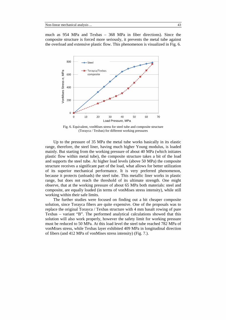
much as 954 MPa and Texbas – 368 MPa in fiber directions). Since the composite structure is forced more seriously, it prevents the metal tube against the overload and extensive plastic flow. This phenomenon is visualized in Fig. 6.
Load Pressure, MPa
Fig. 6. Equivalent, vonMises stress for steel tube and composite structure (Torayca / Texbas) for different working pressures
Up to the pressure of 35 MPa the metal tube works basically in its elastic range, therefore, the steel liner, having much higher Young modulus, is loaded mainly. But starting from the working pressure of about 40 MPa (which initiates plastic flow within metal tube), the composite structure takes a bit of the load and supports the steel tube. At higher load levels (above 50 MPa) the composite structure receives a significant part of the load, what allows for better utilization of its superior mechanical performance. It is very preferred phenomenon, because it protects (unloads) the steel tube. This metallic liner works in plastic range, but does not reach the threshold of its ultimate strength. One might observe, that at the working pressure of about 65 MPa both materials: steel and composite, are equally loaded (in terms of vonMises stress intensity), while still working within their safe limits.
The further studies were focused on finding out a bit cheaper composite solution, since Torayca fibers are quite expensive. One of the proposals was to replace the original Torayca / Texbas structure with 4 mm basalt rowing of pure Texbas – variant “B”. The performed analytical calculations showed that this solution will also work properly, however the safety limit for working pressure must be reduced to 50 MPa. At this load level the steel tube reached 782 MPa of vonMises stress, while Texbas layer exhibited 409 MPa in longitudinal direction of fibers (and 412 MPa of vonMises stress intensity) (Fig. 7.).
Von
Mis
es S
tres
s σ,
MP
a

44 T. Nowak, J. Schmidt
Fig. 7. Results of analytical calculations for working pressure of 50 MPa – variant “B”
This second design case – the structure consisting of metal tube (φ185/193) and basalt rowing (φ193/201) was also confirmed by FEM study, as presented in the next paragraph.
3.4. FEM Analysis
The object under study was verified numerically by ABAQUS, Finite Element Method software package. Due to the axial symmetry, only ¼ of the model was discretized. The FE mesh, involving parabolic elements of 20 nodes per element, is shown in Fig. 8. All the material properties, as well as loads, were applied in the same way as in analytical calculation approach. Due to elasto-plastic behavior of the steel tube, the non-linear procedure was used for computation. The composite’s plies were modeled as a separate layer in FE model, having the equivalent material properties.
It is also worth noted, that numerical analysis was based on Lame’s theory (for thin-walled cylinders), thus, being more accurate, it was treated as verification run for the analytical approach described in chapter 2.
Fig. 8. FE model of the analyzed cylinder

Non-linear mechanical analysis ... 45
Some of the numerical results for the composite structure at the working pressure of 50 MPa are provided in the Fig. 9.
Please note, that main part of the basalt rowing is loaded at the level of 415 MPa, what agrees very well with analytical prediction (412 MPa), Fig. 10. In addition, the FEM study exhibited also some bending effect (not covered by analytical calculations), which increased a bit the level of stress intensity to 435 MPa at the area localized near the end plate (not shown in the Fig. 9).
Fig. 9. Equivalent von Mises stress for the composite layer at the load of 50 MPa (cut view)
Fig. 10. Equivalent von Mises stress for the Texbas layer (variant “B”) at the load of 50 MPa – comparison between results of FEM study and analytical calculation model

46 T. Nowak, J. Schmidt
4. Laboratory measurements and test verifications
According to the cylinder design proposed in Chapter 3.2, the testing samples have been produced. First, the steel liners were prepared and overwrapped by plies of the fibers, while the epoxy resin was provided during winding. Finally, the testing members were subjected to thermal treatment in order to cure and post-cure the epoxy matrix. The measurement procedure introduced the hydraulic load, which was realized by the specially designed tool allowing to increase the working pressure slowly. The testing load was controlled by the pressure gauge, while deformations (strains) of the sample were monitored by foil strain gauges glued to the external surface of the test tube. The load was incrementally increased during measurements, while strain results were recorded. The testing procedure was continued until the damage of the composite layer was seen.
To support the measurements, the Acoustic Emission technique was used to monitor the onset and progress of the failure. The pattern recognition method (Visuall-Class Vallen) helped to identify groups of signals responsible for various failure modes. It reported damage of the composite layer. The cracks appeared along the axial direction, what confirmed the dominant role of hoop stresses in failure mechanism. The observed onset of the fracture agreed very well with numerical calculations. The measured specimens performed fully in the elastic range at the pressure level of 35 MPa. When crossing this load, the metal tube started to flow, what exhibited in higher results of strain gauge readings. The level of 50 MPa was safely achieved for test samples. The damaging failure was noted at the load of 65-70 MPa (depending on the sample), what is about 2.5-times bigger than working pressure of 25 MPa.
The exemplary test sample during laboratory measurements is shown in Fig. 11.
5. Conclusions
This paper investigated the stress-strain behavior of the composite-reinforced steel cylinder exposed to the internal pressure and the external axial load. Since the increase of the cylinder’s power-per-weight ratio was the main objective of the study, it was necessary to load the steel liner above its elastic limit. It required the detailed analysis of the structure, which included modeling of the metal plasticity and orthotropic properties of the composite reinforcement. The respective analytical calculation approach was proposed, and then validated by the numerical FE study. The optimal design parameters of the pressurized vessel were found. The steel tube was designed to have the thickness of 4 mm, while the composite shell of the same thickness was made of Texbas rowing

Non-linear mechanical analysis ... 47
Fig. 11. Test sample during the measurements
at the angle of ±2˚. Thanks to this configuration much lower weight of the cylinder could be safely ensured for different load scenarios (ratio between working pressure and axial load). The test specimens were produced according to the proposed design parameters, and have been subjected to the extensive testing program. It was generally found, that composite reinforcement provides a big support when the metal liner approaches the plastic deformation. If this happen, the composite structure takes much of the load, and ensures that the metal tube is not overloaded. However, if the steel liner works within its elastic limit, the contribution of the composite reinforcement is not very significant. The physical observations made during the laboratory tests fully confirmed the results of earlier analytical and numerical analysis.
Acknowledgment
The authors express their appreciation for support of Polish Ministry of Science and Higher Education for its financial support to this study (project NR 15005906).
48 T. Nowak, J. Schmidt
References
[1] R. HILL: The mathematical theory of plasticity. Clarendon Press, Oxford 1950. [2] A. MENDELSON: Plasticity: theory and applications. The Macmillann Company,
New York 1968. [3] J. CHAKRABRY: Theory of plasticity. McGraw-Hill, New York 1987. [4] D.M. FRYER, and J.F. HARVEY: High pressure vessels, Chapman & Hill,
London 1998. [5] D. DURBAN, and M. KUBI: A general solution for the pressurized elastoplastic
tubes. Journal Appl. Mech., 59(1992), 20-26. [6] A.P. PARKER: Autofrettage of open end tubes – pressures, stresses, strains and
code comparisons. Journal Pressure Vessel Technol., 123(2001), 271-281. [7] W. ZHAO, R. SESHADRI, R.N. DUBEY: On Thick-walled cylinder under internal
pressure. Journal Pressure Vessel Technol., 125(2003), 267-273. [8] J. PERRY and J. ABOUDI: Elasto-plastic stresses in thick walled cylinders. ASME
Journal Pressure Vessel Technol., 125(2003), 248-252. [9] G. WIDLAK: Radial return method applied in thick-walled cylinder analysis.
Journal of Theor. and App. Mech., 48(2010)2, 381-395. [10] D. GAY, S.V. HOA, S.W. TSAI: Composite materials: design and applications.
CRC Press, 2002. [11] R. JONES: Mechanics of composite materials, 2nd ed. CRC Press, 1998. [12] P.K. MALLICK: Composites engineering handbook. CRC Press, 1997. [13] P.D. SODEN, R. KITCHING and P.C. TSE: Experimental failure stresses for ±55˚
filament wound glass fiber reinforced plastic tubes under biaxial loads. Composites, 20(1989), 125-135.
[14] J. MISTERY, A.G. GIBSON and Y-S. WU: Failure of composite cylinders under combined external pressure and axial loading. Composites Structure, 22(1992), 193-200.
[15] M. XIA, K. KEMMOCHI and H. TAKAYANAGI: Analysis of filament-wound fiber-reinforced sandwitch pipe under combined internal pressure and thermo-mechanical loading. Composites Structure, 51(2001), 273-283.
[16] M. UEMURA, and H. FUKUNAGA: Probabilistic burst strength of filament-wound cylinders under internal pressure. Journal Comp. Mater., 15(1991), 462-480.
[17] J.M. LIFSHITZ, and H.M. DAYAN: Filament-wound pressure vessel with thick metal line. Composites Structure, 32(1995), 313-323.
[18] P. CZARNOCKI: Interlaminar fracture toughness of selected fibre-reinforced polymer matrix composites. Advances Manufacturing Science and Technology, 34(2010)2, 47-58.
[19] P.M. WILD, and G.W. VICKERS: Analysis of filament-wound cylindrical shells under combined centrifugal pressure and axial loading. Composites Part A, 28(1997), 47-55.
Received in April 2013