noise and blast management plan - holcim.com.au jandra quarry environmental management strategy ii...
TRANSCRIPT

Strength. Performance. Passion.
Noise and Blast Management Plan Jandra Quarry
Holcim Australia Pty. Ltd.
© 2015 Holcim Country Company Name 1
Holcim Jandra Quarry Environmental Management Strategy i Noise & Blast Management Plan
CONTENTS INTRODUCTION 1 1
Context 1 1.1 Background 1 1.2 Environmental Management Document System 1 1.3 NBMP approval 1 1.4
PURPOSE AND OBJECTIVES 3 2
Purpose 3 2.1 Objectives 3 2.2 Targets 3 2.3
ENVIRONMENTAL REQUIREMENTS 4 3
Relevant legislation and guidelines 4 3.1 Legislation 4 3.1.1 Guidelines and standards 4 3.1.2
Minister’s Conditions of Approval 4 3.2
EXISTING ENVIRONMENT 8 4
Identified Sensitive Receivers 8 4.1 Existing Acoustical Environment 9 4.2
Continuous Unattended Noise Monitoring 9 4.2.1 Operator Attended Noise Surveys 4.2.2
NOISE & BLASTING CRITERIA 12 5
Noise Criteria 12 5.1 Blasting Criteria 12 5.2
Airblast Criteria 13 5.2.1 Vibration Criteria 14 5.2.2
ENVIRONMENTAL ASPECTS & IMPACTS 15 6
Development Activities 15 6.1 Influences 15 6.2 Impacts 16 6.3
Operational Noise 16 6.3.1 Sleep Disturbance 6.3.2
ENVIRONMENTAL CONTROL MEASURES 17 7
COMPLIANCE MANAGEMENT 19 8
Inspections & Monitoring 19 8.1 Noise monitoring 19 8.1.1 Blast monitoring 19 8.1.2
Training 20 8.2 Licenses and permits 20 8.3 Complaints and enquiries procedure 20 8.4 Auditing and reporting 20 8.5
Holcim Jandra Quarry Environmental Management Strategy ii Noise & Blast Management Plan
REVIEW AND IMPROVEMENT 21 9
Continuous improvement 21 9.1 NBMP update and amendment 21 9.2
Figures
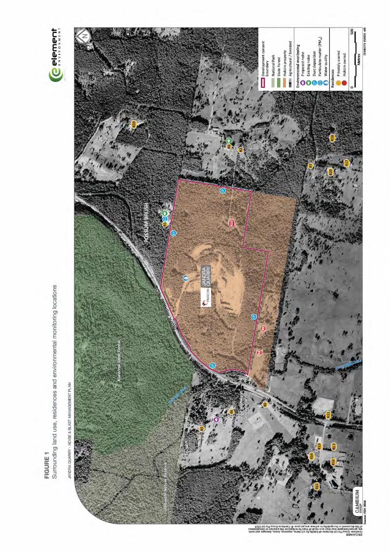
Figure 1 Surrounding land use, residences and environmental monitoring locations 11
Tables
Table 1 Conditions of Approval relevant to the NBMP 4 Table 2 Noise sensitive receptor locations 8 Table 3 Summary of existing Rating Background Levels and existing Ambient Noise Levels 9 Table 4 Existing road traffic noise 9 Table 5 Operator attended survey results Table 6 Noise criteria - quarrying operations only dB(A) Table 7 Noise criteria – quarrying operations & asphalt plant production combined dB(A) Table 8 Acceptable MIC (kg) to meet ANZEC Guidelines for human comfort Table 9 Airblast overpressure criteria Table 10 Peak particle velocity criteria Table 11 Stage 1 without asphalt plant operating (exceedances shown in bold) Table 12 Stage 1 without asphalt plant operating and early morning shoulder restrictions (exceedances shown in bold) Table 13 Stage 1 with asphalt plant operating (exceedances shown in bold) Table 14 Stage 2 without asphalt plant (exceedances shown in bold) Table 15 Stage 2 without asphalt plant operating and early morning shoulder restrictions (exceedances shown in bold) Table 16 Stage 2 with asphalt plant operating (exceedances shown in bold Table 17 Stage 3 without asphalt plant operating (exceedances shown in bold) Table 18 Stage 3 without asphalt plant operating, early morning shoulder restrictions and no works at or above RL50 during the day/evening (exceedances shown in bold) Table 19 Stage 3 with asphalt plant operating (exceedances shown in bold) Table 20 Sleep disturbance assessment (exceedances shown in bold) Table 21 Environmental Controls & Mitigation Measures
Appendices
Appendix A Jandra Quarry Blast Management Procedure
Holcim Jandra Quarry Environmental Management Strategy iii Noise & Blast Management Plan
GLOSSARY / ABBREVIATIONS ANZEC The Australian and New Zealand Environment Council BoM Australian Bureau of Meteorology Compliance audit Verification of how implementation is proceeding with respect to a
construction environmental management plan (EMS) (which incorporates the relevant approval conditions).
CoA Conditions of Approval for Modification Application No. DA-231-10-99 MOD 5.
dBA Decibels using the A-weighted scale measured according to the frequency of the human ear.
Department, the NSW Department of Planning and Environment. DP&E NSW Department of Planning and Environment EA Environmental Assessment Ecological sustainable development
Using, conserving and enhancing the community’s resources so that the ecological processes on which life depends are maintained and the total quality of life now and in the future, can be increased (Council of Australian Governments, 1992).
ECP Environmental Compliance Planner (Guideline 4.1 Permits, Licences and Approvals, Attachment 4.1E, Issue Date: February 2014).
EPA NSW Environment Protection Authority EMS Environmental management strategy Environmental aspect Defined by AS/NZS ISO 14001:2004 as an element of an
organisation’s activities, products or services that can interact with the environment.
Environmental impact Defined by AS/NZS ISO 14001:2004 as any change to the environment, whether adverse or beneficial, wholly or partially resulting from an organisation’s environmental aspects.
Environmental incident A set of circumstances that causes, or threatens to cause, material harm to the environment; and/or breaches or exceeds the limits or performance measures/criteria in the Conditions of Approval.
Environmental objective Defined by AS/NZS ISO 14001:2004 as an overall environmental goal, consistent with the environmental policy, that an organisation sets itself to achieve.
Environmental policy Statement by an organisation of its intention and principles for environmental performance.
Environmental target Defined by AS/NZS ISO 14001:2004 as a detailed performance requirement, applicable to the organisation or parts thereof, that arises from the environmental objectives and that needs to be set and met in order to achieve those objectives.
EP&A Act Environmental Planning and Assessment Act 1979 EPL Environment Protection Licence Feasible Feasible relates to engineering considerations and what is practical to
build or carry out. INP NSW Industrial Noise Policy (as updated from time-to-time) LEP Local Environmental Plan Leq Equivalent continuous sound level - the constant sound level which,
Holcim Jandra Quarry Environmental Management Strategy iv Noise & Blast Management Plan
when occurring over the same period of time, would result in the receiver experiencing the same amount of sound energy.
LAeq (15min) The A-weighted equivalent continuous (energy average) A-weighted sound pressure level of the activity under consideration over a 15-minute period and excludes other noise sources such as from industry, road, rail and the community.
LA (max) The A-weighted maximum noise level only from the activity under consideration, measured using the fast time weighting on a sound level meter.
L90 The sound pressure level exceeded for 90% of the measurement period. For 90% of the measurement period it was louder than the L90.
MIC Maximum Instantaneous Charge Minister, the Minister for Planning and Environment, or delegate. MOD 5 Modification Application No. DA 231-10-99 MOD 5. Non-compliance Failure to comply with the requirements of the Project approval or any
applicable license, permit or legal requirements. Non-conformance Failure to conform to the requirements of Project system
documentation or supporting documentation. NOW NSW Office of Water
OEH NSW Office of Environment and Heritage PIN Penalty Infringement Notice POEO Act Protection of the Environment Operations Act 1997 Quarrying operations The extraction, processing and transportation of extractive materials
on the site and the associated removal of vegetation, topsoil and overburden.
Quarry products Includes all saleable quarry products, but excludes tailings and other wastes
RBL The Rating Background Level for each period is the medium value of the assessment background level for the period over all of the days measured. There is therefore an RBL value for each period (day, evening and night).
Reasonable Reasonable relates to the application of judgement in arriving at a decision, taking into account: mitigation benefits, cost of mitigation versus benefits provided, community views and the nature and extent of potential improvements
Rehabilitation The restoration of land disturbed by the development to a good condition, ensuring it is safe, stable, non-polluting environment and appropriately vegetated.
RL Reduced level RMS Roads and Maritime Services RNP NSW Road Noise Policy Secretary, the Secretary of the NSW Department of Planning and Environment (or
delegate). SPL Sound Pressure Level, the amount of sound at a specified point. SWL Sound Power Level, the total sound emitted by a source.
Holcim Jandra Quarry Environmental Management Strategy v Noise & Blast Management Plan
DOCUMENT CONTROL Revision Date Description By Review Approved
A Draft report D. Green 9/08/15 26/08/15
B Draft report with Holcim review D. Lidbetter & I. Shenton
27/08/15 30/08/15
Final draft Final draft report D. Green 31/08/15 31/08/15
Holcim Jandra Quarry Environmental Management Strategy 1 Noise & Blast Management Plan
INTRODUCTION 1
Context 1.1A Noise and Blast Management Plan was developed for Jandra Quarry following the Environmental Impact Statement (EIS) and subsequent development consent issued on 30 March 2000 (DA-231-10-99).
This Noise and Blast Management Plan (NBMP or Plan) forms part of the Environmental Management Strategy (EMS) for the Jandra Quarry. This NBMP has been prepared to meet the requirements of the Minister’s Conditions of Approval (CoA) for the Jandra Quarry Intensification in Production Modification (DA-231-10-99 MOD 5) and supersedes all previous versions.
This NBMP has been prepared to address the CoA, the mitigation measures listed in the Jandra Quarry Intensification in Production Environmental Assessment (EA) and all applicable legislation.
Background 1.2Hard rock extraction involves blasting and the use of large bulk earthwork machinery, which combined with processing equipment such as crushers, generate noise and vibration. Consequently a noise and blasting assessment was undertaken during the EA and considered the potential impacts of the modification on nearby sensitive residential receivers.
The noise and blasting assessment in the EA utilised a computer noise model developed for each of the three stages of the quarry’s life, with the quarry stages modelled to reflect ‘worst case’ operations and associated noise impacts at residential receptor locations. The model inputs included local topography and existing ground contour information, sound power levels of quarry plant and equipment, ground contour information based upon future stages of the quarry’s life and meteorological information.
Environmental Management Document System 1.3The environmental management document system is described in Section 5.1 of the EMS.
The NBMP is part of Holcim’s environmental management strategy for Jandra Quarry and is a requirement of CoA 4 of Schedule 3.
Management measures identified in this NBMP will be incorporated into relevant Work Method Statements (WMS) and the Blast Management Procedure.
Work Method Statements are approved by the Quarry Manager. Operational personnel are required to undertake works in accordance with the safeguards identified in WMS.
The review, auditing and document control processes for this NBMP are described in Sections 9, 10 & 11 of the EMS.
NBMP approval 1.4This NBMP must be endorsed by the Quarry Manager prior to submission to the Secretary of the Department of Planning & Environment (DP&E).
Submission of the NBMP for the approval of the Secretary is required no later than 31 August 2015 or as otherwise agreed by the Secretary. Intensification activities approved by

Holcim Jandra Quarry Environmental Management Strategy 2 Noise & Blast Management Plan
the CoA will not commence until written approval of the EMS and this Plan has been received from the Secretary.
Holcim Jandra Quarry Environmental Management Strategy 3 Noise & Blast Management Plan
PURPOSE AND OBJECTIVES 2
Purpose 2.1The purpose of this NBMP is to describe how Holcim proposes to manage noise and blast impacts during the operational lifetime of Jandra Quarry.
Objectives 2.2The key objective of the NBMP is to ensure that impacts to the local community and the built environment from noise and vibration are minimised.
To achieve this objective, Holcim will undertake the following:
identifying sensitive receivers and ensuring appropriate environmental controls and procedures are implemented during operational activities;
minimising potential adverse noise and vibration impacts to the environment and community;
managing impacts if they occur through a systematic analysis of mitigation strategies;
ensure appropriate measures are implemented to address the relevant CoA outlined in Table 1 and the EA mitigation measures detailed in Table 10; and
ensure appropriate measures are implemented to comply with all relevant legislation and other requirements as described in Section 3.1.1 of this NBMP.
Targets 2.3The following targets have been established for the management of noise and blasting impacts during the operational lifetime of Jandra Quarry:
ensure full compliance with the relevant legislative requirements and CoA;
feasible and reasonable noise mitigation measures are implemented with the aim of achieving the noise management levels detailed in the NSW Industrial Noise Policy (EPA, 2000);
blasting activities are only undertaken during approved operating times and compliant with blasting criteria; and
complaints from the community and stakeholders are minimised.
Holcim Jandra Quarry Environmental Management Strategy 4 Noise & Blast Management Plan
ENVIRONMENTAL REQUIREMENTS 3
Relevant legislation and guidelines 3.1
Legislation 3.1.1
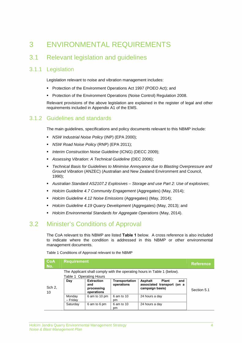
Legislation relevant to noise and vibration management includes:
Protection of the Environment Operations Act 1997 (POEO Act); and
Protection of the Environment Operations (Noise Control) Regulation 2008.
Relevant provisions of the above legislation are explained in the register of legal and other requirements included in Appendix A1 of the EMS.
Guidelines and standards 3.1.2
The main guidelines, specifications and policy documents relevant to this NBMP include:
NSW Industrial Noise Policy (INP) (EPA 2000);
NSW Road Noise Policy (RNP) (EPA 2011);
Interim Construction Noise Guideline (ICNG) (DECC 2009);
Assessing Vibration: A Technical Guideline (DEC 2006);
Technical Basis for Guidelines to Minimise Annoyance due to Blasting Overpressure and Ground Vibration (ANZEC) (Australian and New Zealand Environment and Council, 1990);
Australian Standard AS2107.2 Explosives – Storage and use Part 2: Use of explosives;
Holcim Guideline 4.7 Community Engagement (Aggregates) (May, 2014);
Holcim Guideline 4.12 Noise Emissions (Aggregates) (May, 2014);
Holcim Guideline 4.19 Quarry Development (Aggregates) (May, 2013); and
Holcim Environmental Standards for Aggregate Operations (May, 2014).
Minister’s Conditions of Approval 3.2The CoA relevant to this NBMP are listed Table 1 below. A cross reference is also included to indicate where the condition is addressed in this NBMP or other environmental management documents.
Table 1 Conditions of Approval relevant to the NBMP
CoA No.
Requirement Reference
Sch 2, 10
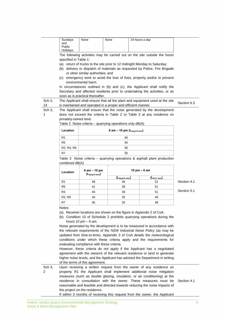
The Applicant shall comply with the operating hours in Table 1 (below). Table 1 Operating Hours
Day Extraction and processing operations
Transportation operations
Asphalt Plant and associated transport (on a campaign basis)
Monday – Friday
6 am to 10 pm 6 am to 10 pm
24 hours a day
Saturday 6 am to 6 pm 6 am to 10 pm
24 hours a day
Section 5.1
Holcim Jandra Quarry Environmental Management Strategy 5 Noise & Blast Management Plan
Sundays and Public Holidays
None None 24 hours a day
The following activities may be carried out on the site outside the hours specified in Table 1: (a) return of trucks to the site prior to 12 midnight Monday to Saturday; (b) delivery or dispatch of materials as requested by Police, Fire Brigade
or other similar authorities; and (c) emergency work to avoid the loss of lives, property and/or to prevent
environmental harm. In circumstances outlined in (b) and (c), the Applicant shall notify the Secretary and affected residents prior to undertaking the activities, or as soon as is practical thereafter.
Sch 2, 14
The Applicant shall ensure that all the plant and equipment used at the site is maintained and operated in a proper and efficient manner.
Section 6.3
Sch 3, 1
The Applicant shall ensure that the noise generated by the development does not exceed the criteria in Table 2 or Table 3 at any residence on privately-owned land. Table 2 Noise criteria – quarrying operations only dB(A)
Location 6 am – 10 pm (LAeq(15 min))
R1 46 R5 40
R2, R4, R6 36
R7 35
Table 3 Noise criteria – quarrying operations & asphalt plant production combined dB(A)
Location 6 am – 10 pm (LAeq(15 min))
10 pm – 6 am
(LAeq(15 min)) (LA1(1 min)) R1 48 46 51 R5 41 39 51
R4 40 39 51
R2, R6 40 35 48
R7 36 35 48
Notes: (a) Receiver locations are shown on the figure in Appendix 2 of CoA. (b) Condition 10 of Schedule 2 prohibits quarrying operations during the
hours 10 pm – 6 am. Noise generated by the development is to be measured in accordance with the relevant requirements of the NSW Industrial Noise Policy (as may be updated from time-to-time). Appendix 3 of CoA details the meteorological conditions under which these criteria apply and the requirements for evaluating compliance with these criteria. However, these criteria do not apply if the Applicant has a negotiated agreement with the owner/s of the relevant residence or land to generate higher noise levels, and the Applicant has advised the Department in writing of the terms of this agreement.
Section 4.1 Section 5.1
Sch 3, 2
Upon receiving a written request from the owner of any residence on property R1 the Applicant shall implement additional noise mitigation measures (such as double glazing, insulation, or air conditioning) at the residence in consultation with the owner. These measures must be reasonable and feasible and directed towards reducing the noise impacts of the project on the residence. If within 3 months of receiving this request from the owner, the Applicant
Section 4.1

Holcim Jandra Quarry Environmental Management Strategy 6 Noise & Blast Management Plan
and the owner cannot agree on the measures to be implemented, or there is a dispute about the implementation of these measures, then either party may refer the matter to the Secretary for resolution. However, the obligation to implement noise mitigation measures does not apply if the Applicant has a negotiated agreement with the owner/s of the relevant residence or land that sets aside noise mitigation measures under the terms of this consent, and the Applicant has advised the Department in writing of the terms of this agreement.
Sch 3, 3
The Applicant shall: (a) implement best practice management to minimise the construction, operational and transportation noise of the development; (b) minimise the noise impacts of the development during meteorological conditions when the noise limits in this consent do not apply (see Appendix 3); (c) carry out regular monitoring to determine whether the development is complying with the relevant conditions of this consent; and (d) regularly assess noise monitoring data and modify and/or stop operations on site to ensure compliance with the relevant conditions of this consent, to the satisfaction of the Secretary.
Section 6.3 Section 8.1
Sch 3, 4
The Applicant shall prepare and implement a Noise Management Plan for the development to the satisfaction of the Secretary. This plan must: (a) be submitted to the Secretary for approval by 31 August 2015; (b) describe the measures that would be implemented to ensure:
compliance with the noise criteria in this consent; best management noise minimisation practice is employed on site; noise emissions from trucks on the site after 10 pm do not annoy
neighbouring residents; and the noise impacts of the development are minimised during any
meteorological conditions when the noise limits in this consent do not apply; and
(c) detail a monitoring program that will be put in place to measure noise from the development against the noise criteria in Table 2 and 3 [of Condition 1 of Schedule 3], and which: includes quarterly attended monitoring for the first two years of
each of the three Stages of the development, as shown in the three figures in Appendix 1 (this monitoring must take place within a 24 hour asphalt campaign, if any such campaign is conducted during the quarter), and thereafter annually unless the Secretary agrees otherwise; and
evaluates and reports on the effectiveness of the noise management system on site.
This Plan
Sch 3, 5
The Applicant shall ensure that blasting on site does not cause any exceedance of the criteria in Table 4. Table 4 Blasting criteria
Location Airblast
overpressure (dB(Lin Peak))
Ground vibration (mm/s)
Allowable exceedance
Any residence on privately owned land, or any public infrastructure
120 10 0%
115 5 5% of the total number of blasts over a period of 12
months However, these criteria do not apply if the Applicant has a written agreement with the relevant owner to exceed the limits in Table 4, and the Applicant has advised the Department in writing of the terms of this agreement.
Section 5.2
Holcim Jandra Quarry Environmental Management Strategy 7 Noise & Blast Management Plan
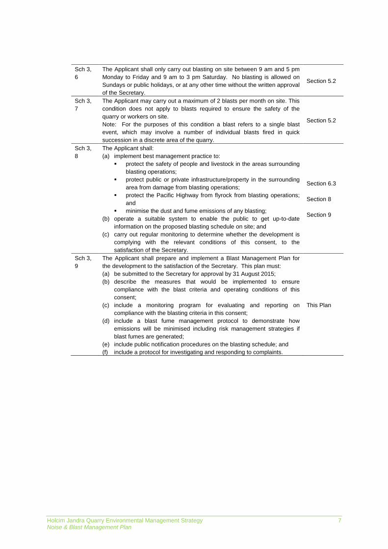
Sch 3, 6
The Applicant shall only carry out blasting on site between 9 am and 5 pm Monday to Friday and 9 am to 3 pm Saturday. No blasting is allowed on Sundays or public holidays, or at any other time without the written approval of the Secretary.
Section 5.2
Sch 3, 7
The Applicant may carry out a maximum of 2 blasts per month on site. This condition does not apply to blasts required to ensure the safety of the quarry or workers on site. Note: For the purposes of this condition a blast refers to a single blast event, which may involve a number of individual blasts fired in quick succession in a discrete area of the quarry.
Section 5.2
Sch 3, 8
The Applicant shall: (a) implement best management practice to:
protect the safety of people and livestock in the areas surrounding blasting operations;
protect public or private infrastructure/property in the surrounding area from damage from blasting operations;
protect the Pacific Highway from flyrock from blasting operations; and
minimise the dust and fume emissions of any blasting; (b) operate a suitable system to enable the public to get up-to-date
information on the proposed blasting schedule on site; and (c) carry out regular monitoring to determine whether the development is
complying with the relevant conditions of this consent, to the satisfaction of the Secretary.
Section 6.3 Section 8 Section 9
Sch 3, 9
The Applicant shall prepare and implement a Blast Management Plan for the development to the satisfaction of the Secretary. This plan must: (a) be submitted to the Secretary for approval by 31 August 2015; (b) describe the measures that would be implemented to ensure
compliance with the blast criteria and operating conditions of this consent;
(c) include a monitoring program for evaluating and reporting on compliance with the blasting criteria in this consent;
(d) include a blast fume management protocol to demonstrate how emissions will be minimised including risk management strategies if blast fumes are generated;
(e) include public notification procedures on the blasting schedule; and (f) include a protocol for investigating and responding to complaints.
This Plan
Holcim Jandra Quarry Environmental Management Strategy 8 Noise & Blast Management Plan
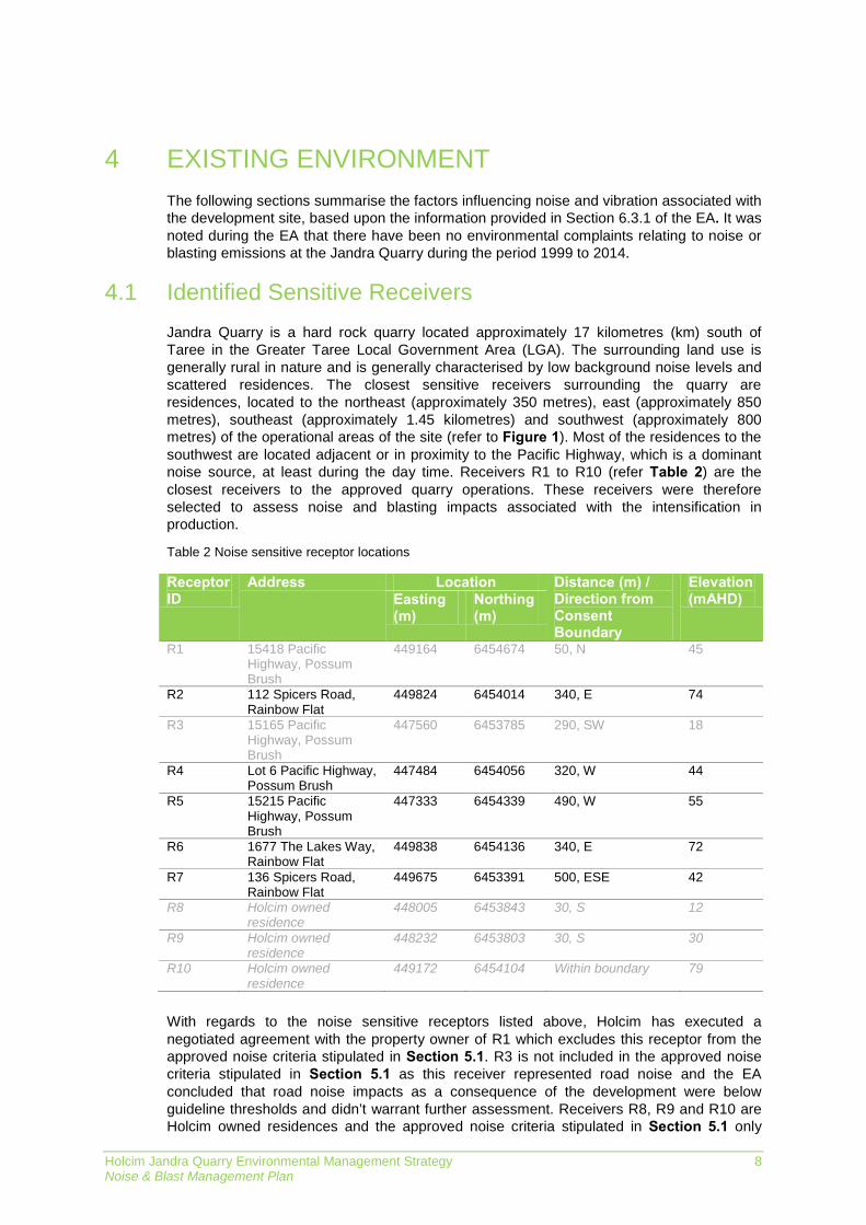
EXISTING ENVIRONMENT 4The following sections summarise the factors influencing noise and vibration associated with the development site, based upon the information provided in Section 6.3.1 of the EA. It was noted during the EA that there have been no environmental complaints relating to noise or blasting emissions at the Jandra Quarry during the period 1999 to 2014.
Identified Sensitive Receivers 4.1Jandra Quarry is a hard rock quarry located approximately 17 kilometres (km) south of Taree in the Greater Taree Local Government Area (LGA). The surrounding land use is generally rural in nature and is generally characterised by low background noise levels and scattered residences. The closest sensitive receivers surrounding the quarry are residences, located to the northeast (approximately 350 metres), east (approximately 850 metres), southeast (approximately 1.45 kilometres) and southwest (approximately 800 metres) of the operational areas of the site (refer to Figure 1). Most of the residences to the southwest are located adjacent or in proximity to the Pacific Highway, which is a dominant noise source, at least during the day time. Receivers R1 to R10 (refer Table 2) are the closest receivers to the approved quarry operations. These receivers were therefore selected to assess noise and blasting impacts associated with the intensification in production.
Table 2 Noise sensitive receptor locations
Receptor ID
Address Location Distance (m) / Direction from Consent Boundary
Elevation (mAHD) Easting
(m) Northing (m)
R1 15418 Pacific Highway, Possum Brush
449164 6454674 50, N 45
R2 112 Spicers Road, Rainbow Flat
449824 6454014 340, E 74
R3 15165 Pacific Highway, Possum Brush
447560 6453785 290, SW 18
R4 Lot 6 Pacific Highway, Possum Brush
447484 6454056 320, W 44
R5 15215 Pacific Highway, Possum Brush
447333 6454339 490, W 55
R6 1677 The Lakes Way, Rainbow Flat
449838 6454136 340, E 72
R7 136 Spicers Road, Rainbow Flat
449675 6453391 500, ESE 42
R8 Holcim owned residence
448005 6453843 30, S 12
R9 Holcim owned residence
448232 6453803 30, S 30
R10 Holcim owned residence
449172 6454104 Within boundary 79
With regards to the noise sensitive receptors listed above, Holcim has executed a negotiated agreement with the property owner of R1 which excludes this receptor from the approved noise criteria stipulated in Section 5.1. R3 is not included in the approved noise criteria stipulated in Section 5.1 as this receiver represented road noise and the EA concluded that road noise impacts as a consequence of the development were below guideline thresholds and didn’t warrant further assessment. Receivers R8, R9 and R10 are Holcim owned residences and the approved noise criteria stipulated in Section 5.1 only
Holcim Jandra Quarry Environmental Management Strategy 9 Noise & Blast Management Plan
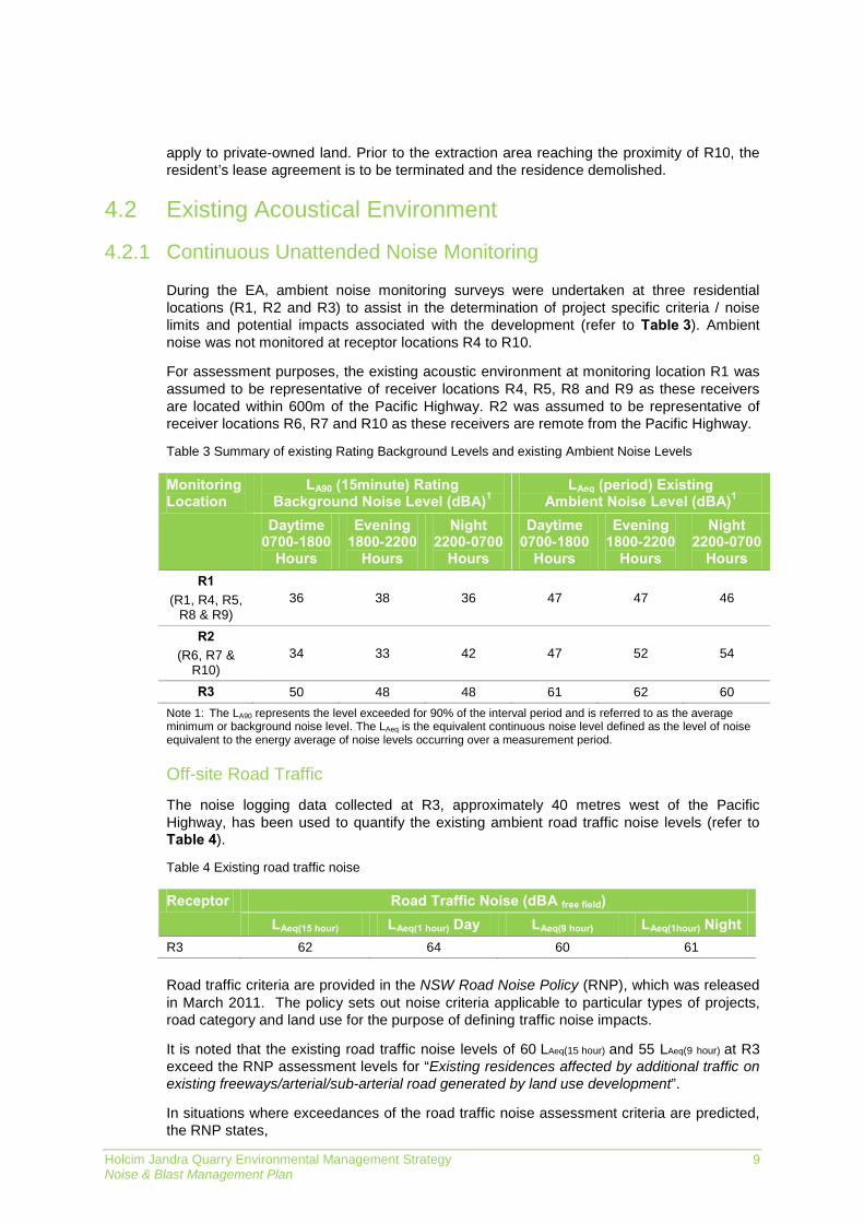
apply to private-owned land. Prior to the extraction area reaching the proximity of R10, the resident’s lease agreement is to be terminated and the residence demolished.
Existing Acoustical Environment 4.2
Continuous Unattended Noise Monitoring 4.2.1
During the EA, ambient noise monitoring surveys were undertaken at three residential locations (R1, R2 and R3) to assist in the determination of project specific criteria / noise limits and potential impacts associated with the development (refer to Table 3). Ambient noise was not monitored at receptor locations R4 to R10.
For assessment purposes, the existing acoustic environment at monitoring location R1 was assumed to be representative of receiver locations R4, R5, R8 and R9 as these receivers are located within 600m of the Pacific Highway. R2 was assumed to be representative of receiver locations R6, R7 and R10 as these receivers are remote from the Pacific Highway.
Table 3 Summary of existing Rating Background Levels and existing Ambient Noise Levels
Monitoring Location
LA90 (15minute) Rating Background Noise Level (dBA)1
LAeq (period) Existing Ambient Noise Level (dBA)1
Daytime 0700-1800
Hours
Evening 1800-2200
Hours
Night 2200-0700
Hours
Daytime 0700-1800
Hours
Evening 1800-2200
Hours
Night 2200-0700
Hours R1
(R1, R4, R5, R8 & R9)
36 38 36 47 47 46
R2 (R6, R7 &
R10) 34 33 42 47 52 54
R3 50 48 48 61 62 60 Note 1: The LA90 represents the level exceeded for 90% of the interval period and is referred to as the average minimum or background noise level. The LAeq is the equivalent continuous noise level defined as the level of noise equivalent to the energy average of noise levels occurring over a measurement period.
Off-site Road Traffic
The noise logging data collected at R3, approximately 40 metres west of the Pacific Highway, has been used to quantify the existing ambient road traffic noise levels (refer to Table 4).
Table 4 Existing road traffic noise
Receptor Road Traffic Noise (dBA free field) LAeq(15 hour) LAeq(1 hour) Day LAeq(9 hour) LAeq(1hour) Night
R3 62 64 60 61 Road traffic criteria are provided in the NSW Road Noise Policy (RNP), which was released in March 2011. The policy sets out noise criteria applicable to particular types of projects, road category and land use for the purpose of defining traffic noise impacts.
It is noted that the existing road traffic noise levels of 60 LAeq(15 hour) and 55 LAeq(9 hour) at R3 exceed the RNP assessment levels for “Existing residences affected by additional traffic on existing freeways/arterial/sub-arterial road generated by land use development”.
In situations where exceedances of the road traffic noise assessment criteria are predicted, the RNP states,
Holcim Jandra Quarry Environmental Management Strategy 10 Noise & Blast Management Plan
“Where existing traffic noise levels are above the noise assessment criteria, the primary objective is to reduce these through feasible and reasonable measures to meet the assessment criteria. A secondary objective is to protect against excessive decreases in amenity as the result of a project by applying the relative increase criteria.
In assessing feasible and reasonable mitigation measures, an increase of up to 2 dB represents a minor impact that is considered barely perceptible to the average person.
…For existing residences and other sensitive land uses affected by additional traffic on existing roads generated by land use developments, any increase in the total traffic noise level should be limited to 2 dB above that of the corresponding ‘no build option’.”
The future change in road traffic noise attributable to the development was calculated using a prediction algorithm which took the following into consideration:
The existing traffic movements on the Pacific Highway as provided in the Traffic Impact Assessment (‘TUP Report’, June 2014);
186 heavy vehicle movements (93 inbound and 93 outbound) on any single day. This figure corresponds to the 85 percentile of the day movements as provided in the TUP Report;
100 heavy vehicle movements during the night period (after 10 pm and before 7:00 am). This figure corresponds to the predicted level of heavy vehicle movements at night during asphalt production campaigns; and
A 50% north south split of truck movements from the site.
On the basis of the above information, the predicted changes in road traffic noise levels resulted in an increase of 0.3 dB during the day period and 1.9 dB during the night period.
The predicted changes are below the threshold of +2 dBA and therefore no further investigations or controls are warranted.

Holcim Jandra Quarry Environmental Management Strategy 11 Noise & Blast Management Plan
Figure 1 Surrounding land use, residences and environmental monitoring locations

Holcim Jandra Quarry Environmental Management Strategy 12 Noise & Blast Management Plan
NOISE & BLASTING CRITERIA 5The following section identifies the development’s noise and blasting criteria approved in the CoA.
Noise Criteria 5.1CoA 1 of Schedule 3 stipulates the development’s approved noise criteria and categorises them according to two scenarios:
Noise criteria when quarrying only operations are being undertaken (refer Table 5); and,
Noise criteria when quarrying and asphalt plant production are both being undertaken (refer Table 6).
Condition 10 of Schedule 2 prohibits quarrying operations during the hours 10pm – 6am.
The approved noise criteria do not apply to R1, R3, R8, R9 and R10. Holcim has executed a negotiated agreement with the property owner of R1 which excludes this receptor from the approved noise criteria. R3 is not included in the approved noise criteria as this receiver represented road noise and the EA concluded that road noise impacts as a consequence of the development were below guideline thresholds and didn’t warrant further assessment. Receivers R8, R9 and R10 are Holcim owned residences and the approved noise criteria only apply to private-owned land.
Table 5 Noise criteria - quarrying operations only dB(A)
Location 6 am – 10 pm (LAeq(15 min)) R1 46 R5 40
R2, R4, R6 36 R7 35
Table 6 Noise criteria – quarrying operations & asphalt plant production combined dB(A)
Location 6 am – 10 pm (LAeq(15 min))
10 pm – 6 am (no quarry operations) (LAeq(15 min)) (LA1(1 min))
R1 48 46 51 R5 41 39 51 R4 40 39 51
R2, R6 40 35 48 R7 36 35 48
Noise generated by the development is to be measured in accordance with the relevant requirements of the NSW Industrial Noise Policy (INP). Appendix 3 of the CoA details the meteorological conditions under which these criteria apply and the requirements for evaluating compliance with these criteria.
Blasting Criteria 5.2Airblast and ground vibration criteria specific to blasting activities are stipulated below:
Holcim shall only carry out blasting on site between 9 am to 5 pm Monday to Friday, and 9 am to 3 pm Saturday;
No blasting will be undertaken on Sundays or public holidays, or at any other time without the written approval of the Secretary of the DP&E;
Holcim Jandra Quarry Environmental Management Strategy 13 Noise & Blast Management Plan
Holcim will carry out a maximum of two blasts per month on site. However this does not apply to blasts which may be required to ensure the safety of the quarry or workers on site; and
A blast refers to a single blast event, which may involve a number of individual blasts fired in quick succession in a discrete area of the quarry.
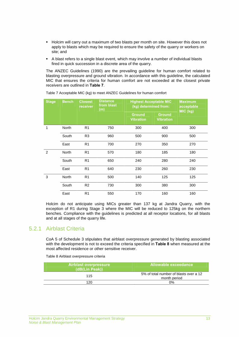
The ANZEC Guidelines (1990) are the prevailing guideline for human comfort related to blasting overpressure and ground vibration. In accordance with this guideline, the calculated MIC that ensures the criteria for human comfort are not exceeded at the closest private receivers are outlined in Table 7.
Table 7 Acceptable MIC (kg) to meet ANZEC Guidelines for human comfort
Stage Bench Closest receiver
Distance from blast (m)
Highest Acceptable MIC (kg) determined from:
Maximum acceptable MIC (kg)
Ground Vibration
Ground Vibration
1 North R1 750 300 400 300
South R3 960 500 900 500
East R1 700 270 350 270
2 North R1 570 180 185 180
South R1 650 240 280 240
East R1 640 230 260 230
3 North R1 500 140 125 125
South R2 730 300 380 300
East R1 550 170 160 160
Holcim do not anticipate using MICs greater than 137 kg at Jandra Quarry, with the exception of R1 during Stage 3 where the MIC will be reduced to 125kg on the northern benches. Compliance with the guidelines is predicted at all receptor locations, for all blasts and at all stages of the quarry life.
Airblast Criteria 5.2.1
CoA 5 of Schedule 3 stipulates that airblast overpressure generated by blasting associated with the development is not to exceed the criteria specified in Table 8 when measured at the most affected residence or other sensitive receiver.
Table 8 Airblast overpressure criteria
Airblast overpressure (dB(Lin Peak))
Allowable exceedance
115 5% of total number of blasts over a 12 month period
120 0%
Holcim Jandra Quarry Environmental Management Strategy 14 Noise & Blast Management Plan
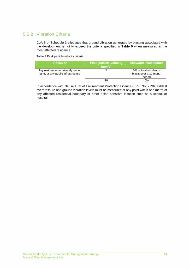
Vibration Criteria 5.2.2
CoA 5 of Schedule 3 stipulates that ground vibration generated by blasting associated with the development is not to exceed the criteria specified in Table 9 when measured at the most affected residence.
Table 9 Peak particle velocity criteria
Receiver Peak particle velocity (mm/s)
Allowable exceedance
Any residence on privately owned land, or any public infrastructure
5 5% of total number of blasts over a 12 month
period 10 0%
In accordance with clause L3.3 of Environment Protection Licence (EPL) No. 2796, airblast overpressure and ground vibration levels must be measured at any point within one metre of any affected residential boundary or other noise sensitive location such as a school or hospital.

Holcim Jandra Quarry Environmental Management Strategy 15 Noise & Blast Management Plan
ENVIRONMENTAL ASPECTS & IMPACTS 6
Development Activities 6.1A range of activities are undertaken at Jandra Quarry utilising various heavy machinery, plant and equipment. Key activities likely to generate noise or vibration are identified below.
clearing and grubbing;
demolition;
earthworks and drainage;
drilling and blasting;
crushing and screening;
load and haul;
plant operation; and
product dispatch and transportation.
Influences 6.2The potential for noise and blast impacts on sensitive receivers will depend on several factors, notably:
the type of equipment in use;
the number of equipment simultaneously in use;
ground condition;
topography and other physical barriers;
proximity to sensitive receivers;
the existing structural condition of sensitive receptors;
hours/duration of activities;
time of day; and
proximity to the highway.

Holcim Jandra Quarry Environmental Management Strategy 16 Noise & Blast Management Plan
Impacts 6.3The EA assessed and predicted noise levels based upon a set of nominated noise criteria referred to as ‘Project Criteria’. Subsequent to DP&E’s review of the EA and determination, a set of slightly varied noise criteria were approved. The section below updates the EA noise assessment, taking into consideration the noise criteria approved in the CoA, in order to understand the potential impact of the development.
Section 6.3 provides mitigation measures that will be implemented to avoid or minimise these impacts on the receiving community.
Operational Noise 6.3.1
During the EA, operational noise from the development was assessed in accordance with INP criteria for the three quarry development stages. Overall noise levels were calculated with and without asphalt production in progress, as asphalt production will not be a regular part of routine operations at Jandra Quarry.
Summary
During normal operations and no asphalt production, compliance with the approved noise criteria stipulated in Section 5.1 is predicted at all privately owned residences, provided operations are restricted during the early morning shoulder period.
During normal operations and asphalt production, compliance with the approved noise criteria stipulated in Section 5.1 is predicted at all privately owned residences, provided operations are restricted during the early morning shoulder period and quarry operations are not undertaken during the night period (10pm to 6am).
Restrictions during the early morning shoulder period for the two scenarios include:
No works in the approved overburden emplacement area;
No works above RL50; and
No operation of the mobile processing plant.
In addition to this meteorological conditions will be monitored using the weather station installed on the Jandra Quarry site to ensure that operations are carried out in accordance with the criteria scheduled in Appendix 3 of the consent. Where meteorological conditions are found to exceed the criteria in Appendix 3 of the consent the site will assess the operations being conducted using the site Noise Control Plan to ensure that all operational noise is minimised.
Holcim Jandra Quarry Environmental Management Strategy 17 Noise & Blast Management Plan
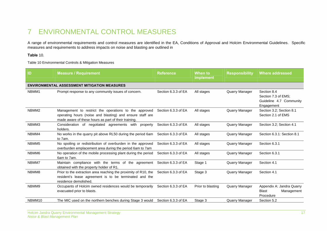
ENVIRONMENTAL CONTROL MEASURES 7A range of environmental requirements and control measures are identified in the EA, Conditions of Approval and Holcim Environmental Guidelines. Specific measures and requirements to address impacts on noise and blasting are outlined in
Table 10.
Table 10 Environmental Controls & Mitigation Measures
ID Measure / Requirement Reference When to implement
Responsibility Where addressed
ENVIRONMENTAL ASSESSMENT MITIGATION MEASURES
NBMM1 Prompt response to any community issues of concern. Section 6.3.3 of EA All stages Quarry Manager Section 8.4 Section 7.3 of EMS; Guideline 4.7 Community Engagement
NBMM2 Management to restrict the operations to the approved operating hours (noise and blasting) and ensure staff are made aware of these hours as part of their training.
Section 6.3.3 of EA All stages Quarry Manager Section 3.2; Section 8.1 Section 2.1 of EMS
NBMM3 Consideration of negotiated agreements with property holders.
Section 6.3.3 of EA All stages Quarry Manager Section 3.2; Section 4.1
NBMM4 No works in the quarry pit above RL50 during the period 6am to 7am.
Section 6.3.3 of EA All stages Quarry Manager Section 6.3.1: Section 8.1
NBMM5 No spoiling or redistribution of overburden in the approved overburden emplacement area during the period 6am to 7am
Section 6.3.3 of EA All stages Quarry Manager Section 6.3.1
NBMM6 No operation of the mobile processing plant during the period 6am to 7am.
Section 6.3.3 of EA All stages Quarry Manager Section 6.3.1
NBMM7 Maintain compliance with the terms of the agreement obtained with the property holder of R1.
Section 6.3.3 of EA Stage 1 Quarry Manager Section 4.1
NBMM8 Prior to the extraction area reaching the proximity of R10, the resident’s lease agreement is to be terminated and the residence demolished.
Section 6.3.3 of EA Stage 3 Quarry Manager Section 4.1
NBMM9 Occupants of Holcim owned residences would be temporarily evacuated prior to blasts.
Section 6.3.3 of EA Prior to blasting Quarry Manager Appendix A: Jandra Quarry Blast Management Procedure
NBMM10 The MIC used on the northern benches during Stage 3 would Section 6.3.3 of EA Stage 3 Quarry Manager Section 5.2
Holcim Jandra Quarry Environmental Management Strategy 18 Noise & Blast Management Plan
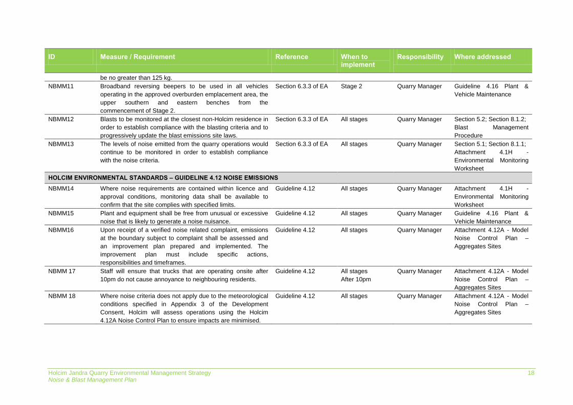
ID Measure / Requirement Reference When to implement
Responsibility Where addressed
be no greater than 125 kg. NBMM11 Broadband reversing beepers to be used in all vehicles
operating in the approved overburden emplacement area, the upper southern and eastern benches from the commencement of Stage 2.
Section 6.3.3 of EA Stage 2 Quarry Manager Guideline 4.16 Plant & Vehicle Maintenance
NBMM12 Blasts to be monitored at the closest non-Holcim residence in order to establish compliance with the blasting criteria and to progressively update the blast emissions site laws.
Section 6.3.3 of EA All stages Quarry Manager Section 5.2; Section 8.1.2; Blast Management Procedure
NBMM13 The levels of noise emitted from the quarry operations would continue to be monitored in order to establish compliance with the noise criteria.
Section 6.3.3 of EA All stages Quarry Manager Section 5.1; Section 8.1.1; Attachment 4.1H - Environmental Monitoring Worksheet
HOLCIM ENVIRONMENTAL STANDARDS – GUIDELINE 4.12 NOISE EMISSIONS
NBMM14 Where noise requirements are contained within licence and approval conditions, monitoring data shall be available to confirm that the site complies with specified limits.
Guideline 4.12 All stages Quarry Manager Attachment 4.1H - Environmental Monitoring Worksheet
NBMM15 Plant and equipment shall be free from unusual or excessive noise that is likely to generate a noise nuisance.
Guideline 4.12 All stages Quarry Manager Guideline 4.16 Plant & Vehicle Maintenance
NBMM16 Upon receipt of a verified noise related complaint, emissions at the boundary subject to complaint shall be assessed and an improvement plan prepared and implemented. The improvement plan must include specific actions, responsibilities and timeframes.
Guideline 4.12 All stages Quarry Manager Attachment 4.12A - Model Noise Control Plan – Aggregates Sites
NBMM 17 Staff will ensure that trucks that are operating onsite after 10pm do not cause annoyance to neighbouring residents.
Guideline 4.12 All stages After 10pm
Quarry Manager Attachment 4.12A - Model Noise Control Plan – Aggregates Sites
NBMM 18 Where noise criteria does not apply due to the meteorological conditions specified in Appendix 3 of the Development Consent, Holcim will assess operations using the Holcim 4.12A Noise Control Plan to ensure impacts are minimised.
Guideline 4.12 All stages Quarry Manager Attachment 4.12A - Model Noise Control Plan – Aggregates Sites

Holcim Jandra Quarry Environmental Management Strategy 19 Noise & Blast Management Plan
COMPLIANCE MANAGEMENT 8
Inspections & Monitoring 8.1Routine inspections by the Quarry Manager (or delegate) will occur throughout the operational lifetime of the development. Detail on the nature and frequency of these inspections are documented in Section 9 of the EMS.
Noise and blast compliance monitoring will also occur throughout the operational lifetime of the development and will be undertaken by a suitably trained professional.
Noise monitoring 8.1.1
Attended noise monitoring is to be undertaken quarterly for the first two years of each of the three stages of the development. This monitoring must take place within a 24 hour asphalt campaign, if any such campaign is conducted during the quarter.
After the first two years of each stage, attended noise monitoring is to be undertaken annually unless the Secretary agrees otherwise.
Noise monitoring will be assessed against the criteria outlined in Section 5.1. All monitoring will be undertaken at the locations specified in Figure 1.
In the event of a non-compliance discovered during noise monitoring will be met with the following actions:
1. Details of the non-compliance will be entered into the INX to log the breach and track corrective actions.
2. Details of the non-compliance including corrective actions will be provided in a report to DP&E at the completion of noise monitoring.
3. The actions implemented following a non-conformance will be reviewed through a risk assessment and during fortnightly environmental inspections.
Blast monitoring 8.1.2
Monitoring of airblast overpressure and ground vibration is to be undertaken for all blast events. Vibration monitoring equipment shall be positioned adjacent to the closest affected privately owned premises to the quarry.
In the event a blast monitoring result is recorded that is outside the criteria of the approval the site will implement the following protocol:
1. Record the result and report as soon as becoming aware of the incident to the Holcim NSW Planning and Environment Manager.
2. If Environmental Harm is believed to have been caused the Quarry Manager will contact the Department of Planning and Environment and the EPA hotline (as soon as becoming aware) to report the details of the incident.
3. Quarry Manager will initiate an investigation to determine the cause or causes of non-conformances.
4. Develop and implement a plan of corrective and preventative action to address any non-conformances identified.

Holcim Jandra Quarry Environmental Management Strategy 20 Noise & Blast Management Plan
5. Provide a report the DP&E and EPA on the findings of the investigation and corrective actions to rectify the incident and prevention measures for future blasts.
Training 8.2All employees and contractors working on site will undergo site induction training, which will cover issues relating to noise and blast management, including:
existence and requirements of this Plan;
relevant legislation;
Jandra Quarry’s operational hours;
location of noise sensitive receivers;
restricted activities during the early morning shoulder; and
complaints reporting.
Further details regarding staff induction and training are outlined in the EMS.
Licenses and permits 8.3EPL No. 2796 is currently in force for the scheduled activities of “Crushing, grinding or separating” and “Extractive activities”. EPL No. 2796 prescribes blasting criteria and monitoring requirements which are consistent with those stipulated in Section 5.2 and Section 8.1.2.
Complaints and enquiries procedure 8.4Wherever possible, a proactive approach will be adopted to engage the community in discussing activities which may affect them. Any complaints that are received relating to the Quarry’s operations will be recorded and responded to according to Section 7.3 of the EMS.
Information to be recorded will include location of complainant, time of occurrence of alleged noise or vibration impacts (including nature of impact particularly with respect to vibration), perceived source, prevailing weather conditions and similar details that could be utilised to assist in the investigation of the complaint.
Auditing and reporting 8.5Audits (both internal and external) and reporting will be undertaken to assess the effectiveness of environmental controls, compliance with this NBMP, CoA and other relevant approvals, licenses and guidelines. Audit requirements are detailed in Section 9.3 of the EMS.
Holcim Jandra Quarry Environmental Management Strategy 21 Noise & Blast Management Plan
REVIEW AND IMPROVEMENT 9
Continuous improvement 9.1Continuous improvement of this NBMP will be achieved in accordance with Section 10 of the EMS, through the ongoing evaluation of environmental management performance against environmental policies, objectives and targets for the purpose of identifying opportunities for improvement.
The continuous improvement process is designed to:
identify areas of opportunity for improvement of environmental management and performance;
determine the cause or causes of non-conformances and deficiencies;
develop and implement a plan of corrective and preventative action to address any non-conformances and deficiencies;
verify the effectiveness of the corrective and preventative actions;
document any changes in procedures resulting from process improvement; and
make comparisons with objectives and targets.
NBMP update and amendment 9.2The processes described in Section 9 and Section 10 of the EMS may result in the need to update or revise this NBMP.
The approval of updates or revisions to the NBMP will need to be considered in accordance with Section 11.2 of the EMS.

Holcim Jandra Quarry Environmental Management Strategy Noise & Blast Management Plan
APPENDIX A: JANDRA QUARRY BLAST MANAGEMENT PROCEDURE
DRILL & BLAST
Procedures
Issue No: 2 Issue Date: February 2013
Page 1
JANDRA QUARRY
DRILL & BLAST
Procedures
DRILL & BLAST
Procedures
Issue No: 2 Issue Date: February 2013
Page 2
CONTENTS
AMENDMENT REGISTER………………………………………………….………………3
DEFINITIONS………………………………………………………………………………..4
REFERENCES………………………………………………………………………………..5
1. RESPONSIBILITIES……………………………………………………………..6
2. SAFETY…………………………………………………………………………..7
3. BLAST DESIGN………………………...……………………………………....8
4. DRILLING PROCESS………………………………………………………........9
5. DRILL MAINTENANCE……………..………………………………………...11
6. LOADING THE BLAST……...…………………………………………………12
7. PREPARATION FOR BLASTING……………......…………………………….15
8. MISFIRES…………………………..……………………………………………17
9. ENVIRONMENTAL and BLAST MONITORING……………………………..18
APPENDIX 1. DRILLING PLAN……………………………………………..…………...19
APPENDIX 2. BLAST COMMUNICATION PLAN………………………………………20
APPENDIX 3. MISFIRES SHE GUIDELINE ATTACHMENT 3.18C…………………...24
APPENDIX 4. NEIGHBOUR CONTACT DETAILS……………………………………..27
APPENDIX 5. DISPOSAL OF EXPLOSIVES……...……………………………………..28
APPENDIX 6. SHOTS LEFT LOADED OVERNIGHT…..……….……………………...32
APPENDIX 7. SHOT LOADING PROCEDURES..……….……………………….……..33
APPENDIX 8. THEFT or LOSS OF EXPLOSIVES….……..……….……………………34
APPENDIX 9. VEHICLES USED TRANSPORT EXPLOSIVES ON A HOLCIM
SITE…………………………………………………………………………………………35
APPENDIX 10. BLASTING CHECKLIST……………………………………………….. 36
DRILL & BLAST
Procedures
Issue No: 2 Issue Date: February 2013
Page 3
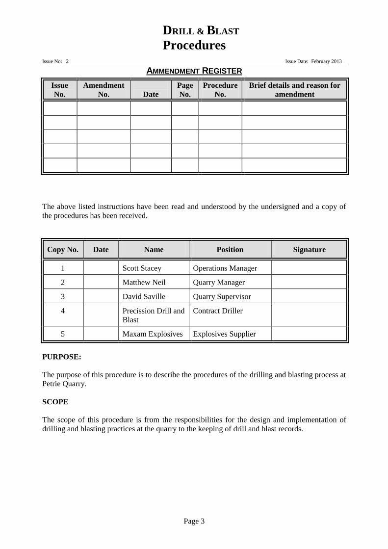
AMMENDMENT REGISTER
Issue
No.
Amendment
No.
Date
Page
No.
Procedure
No.
Brief details and reason for
amendment
The above listed instructions have been read and understood by the undersigned and a copy of
the procedures has been received.
Copy No. Date Name Position Signature
1 Scott Stacey Operations Manager
2 Matthew Neil Quarry Manager
3 David Saville Quarry Supervisor
4 Precission Drill and
Blast
Contract Driller
5 Maxam Explosives Explosives Supplier
PURPOSE:
The purpose of this procedure is to describe the procedures of the drilling and blasting process at
Petrie Quarry.
SCOPE
The scope of this procedure is from the responsibilities for the design and implementation of
drilling and blasting practices at the quarry to the keeping of drill and blast records.
DRILL & BLAST
Procedures
Issue No: 2 Issue Date: February 2013
Page 4
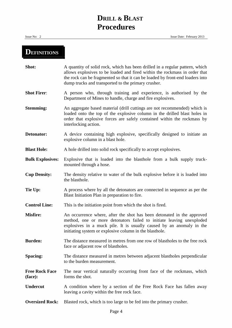
DEFINITIONS
Shot: A quantity of solid rock, which has been drilled in a regular pattern, which
allows explosives to be loaded and fired within the rockmass in order that
the rock can be fragmented so that it can be loaded by front-end loaders into
dump trucks and transported to the primary crusher.
Shot Firer: A person who, through training and experience, is authorised by the
Department of Mines to handle, charge and fire explosives.
Stemming: An aggregate based material (drill cuttings are not recommended) which is
loaded onto the top of the explosive column in the drilled blast holes in
order that explosive forces are safely contained within the rockmass by
interlocking action.
Detonator: A device containing high explosive, specifically designed to initiate an
explosive column in a blast hole.
Blast Hole: A hole drilled into solid rock specifically to accept explosives.
Bulk Explosives: Explosive that is loaded into the blasthole from a bulk supply truck-
mounted through a hose.
Cup Density: The density relative to water of the bulk explosive before it is loaded into
the blasthole.
Tie Up: A process where by all the detonators are connected in sequence as per the
Blast Initiation Plan in preparation to fire.
Control Line: This is the initiation point from which the shot is fired.
Misfire: An occurrence where, after the shot has been detonated in the approved
method, one or more detonators failed to initiate leaving unexploded
explosives in a muck pile. It is usually caused by an anomaly in the
initiating system or explosive column in the blasthole.
Burden: The distance measured in metres from one row of blastholes to the free rock
face or adjacent row of blastholes.
Spacing: The distance measured in metres between adjacent blastholes perpendicular
to the burden measurement.
Free Rock Face The near vertical naturally occurring front face of the rockmass, which
(face): forms the shot.
Undercut A condition where by a section of the Free Rock Face has fallen away
leaving a cavity within the free rock face.
Oversized Rock: Blasted rock, which is too large to be fed into the primary crusher.
DRILL & BLAST
Procedures
Issue No: 2 Issue Date: February 2013
Page 5
REFERENCES
Australian Standard AS 2187.0 - 1998: Explosive - Storage, Transport and Use - Terminology
Australian Standard AS 2187.1 - 1998: Explosives - Storage, Transport and Use - Storage
Australian Standard AS 2187.2 - 1993: Explosives - Storage, Transport and Use - Use of
Explosives
Explosives Act 1999
Explosives Regulation 2003
Australian Code for the Transport of Explosives by road and Rail Second Edition March 2000
DRILL & BLAST
Procedures
Issue No: 2 Issue Date: February 2013
Page 6
PROCEDURE
1. RESPONSIBILITIES
1.1. The Quarry Manager appointed by HOLCIM is the Statutory Production
Manager under the relevant Mines Act who is responsible for the design of the shot
and the implementation of this Drill and Blast Procedure at the Jandra Quarry.
1.2. The Shot Firer authorised under the relevant Mines Act is in control of the
handling, charging and firing of explosives at the quarry. It is the shot firer’s
responsibility to fill in all documentation accurately and refer any shot loading
anomalies to the Quarry Manager immediately upon occurrence. The shotfirer may
be an employee of HOLCIM or the Explosives services provider.
1.3. The Drill Rig Operator is responsible for operating the drill rig in a safe manner,
complying to Section 4 of this procedure and reporting any drilling anomaly to the
Quarry Manager.
1.4. The bulk explosives supplier is responsible for carrying out all blasting activities
in a safe, professional manner ensuring strict compliance to their company safety
procedures as a minimum standard. They shall also be responsible for the safe
delivery of the specified explosives at the correct cup density and weight in order
that no overcharging occurs in any blasthole. They shall be responsible for the
removal from the site to storage of any unused explosives.
DRILL & BLAST
Procedures
Issue No: 2 Issue Date: February 2013
Page 7
2. SAFETY
2.1 All persons involved in Drilling & Blasting shall have been adequately trained, qualified
and have been fully inducted to the Site & the job prior to commencing any work
complying with SHE Guideline 3.18 Blasting and Explosives, Jandra site procedures and
risk assessments. Documented evidence of all relevant training and risk assessments shall
be filed on site.
2.2 The Blasting contractor shall complete their own company Blasting Risk assessment.
2.3 All drilling and blasting operations are to be carried out strictly in accordance with
HOLCIM and MAXAM approved Procedures, Jandra site Procedures, the explosives act
1999, the explosive regulation 2003 and AS2187.1 - 1998, and AS 2187.2 - 1993.
2.4 Vehicle access and / or movement directly over the top of charged blastholes at the shot is
strictly forbidden.
2.5 Good communication between the Quarry Manager, Shot Firer, the Drill rig operator and
explosive supplier is of paramount importance in order to ensure the blast designs are
implemented correctly and any anomalies in any part of the drill and blast process are
highlighted and dealt with in a safe and timely manner.
2.6 The transport of explosives within the mine site in particular is to be carried out strictly in
accordance SHE Guideline attachment 3.18G (refer appendix 9) and the Australian Code
for Transport of explosives by Road and Rail, second Edition, March 2000. Detonators
and boosters shall be separated and protected from each other and other explosives in a
“Day Box” in a separate vehicle, so that the explosion of detonators cannot initiate other
explosives.
2.7 The blasting warning lights in the vicinity of the site office shall note the intention of a
blast and all employees will be notified approximate time of blast. A sign will be placed at
the entrance to the Quarry. The time of the blasting shall be restricted to between 0900 and
1500.
2.8 Prior to loading a shot, verbal notification shall be given to the neighbours advising them
of the approximate time of blast. Refer to Appendix 4, contact details.
2.9 There shall be no unauthorised access into the location of the shot area.
2.10 Mobile Equipment Lock Out Procedures shall apply to equipment associated with drilling
& blasting.
2.11 The procedures contained within this document shall be carried out in conjunction with the
following Job Safety Assessments and Work Instructions.
JSA 008 - Drilling
JSA 009 – House Keeping
JSA 012 - Shot Firing
JSA 017 - Working With Hardened Steel Components
JSA 042 – Changing High Pressure hoses in general
WI : 2 - Drilling
WI : 3 - Blasting

DRILL & BLAST
Procedures
Issue No: 2 Issue Date: February 2013
Page 8
3. BLAST DESIGN
3.1 The blast design is the responsibility of the Quarry Manager. The blast design must
take into account any risk associated from face stability which may cause rock or
face subsidence, especially in terminal faces. This is to be done in conjunction
with the Quarry Development plan, Geotechnical information plus that of previous
shot results and site history. Document any trials done and their technical approach
used in design (egg pre splitting and face angle of terminal faces). The design must
be agreed with the Shotfirer and the pattern recorded on the Drilling Plan, refer to
Appendix 1.
3.2 The face must be profiled using a laser profile technique and bore tracking method,
and once every three months or at random times a spot check of holes throughout
the shot are to bore tracked to check the accuracy of drilling. In most cases, this is
considered the only accurate method of establishing undercut situations. Shots
shall only be initiated where by any undercuts have been identified and over
pressure is therefore controlled.
3.3 Drilling Plans shall be accurately set out on a clean bench that it is free from
obstacles and a surface that is considered safe to work on. The face holes are
positioned first to accommodate any undercutting of the face, and possible
additional “stab” holes for any excessive burden. Stab holes should be used with
extreme care, and where possible be avoided. The front holes, where undercutting
has occurred shall be plotted during the bore tracking process and loaded
accordingly. This will reduce face blow out and fly rock and reduce overpressure.
3.4 Drill holes should not be located so close to the face as to create a fall hazard where
the blast crew could slip or fall over the edge. Should the pre-drilling survey
indicate that a hole should be located so close to the face that it presents an
unacceptable fall risk to operator then toe holes, drilled from the bench below
should be considered. If the operator is required to be within 1.5 metres of the
face, then the front guard must be fitted to drill or fall arrest equipment must be
provided.
3.5 Once the front holes have been positioned, the remainder of the blast holes should
be laid out using marker paint and a legible tape measure. The burdens and
spacings must be measured accurately with holes marked using a small rock and
fluorescent paint. The drill site should be demarcated by flagging or barricades to
prevent the hole positions being interfered with.
3.6 Blast hole depths shall be determined during the Laser Profiling technique and a
plan produced that clearly shows:
Blast hole location
Blast hole diameter
Drill hole depth including the required Sub grade and
DRILL & BLAST
Procedures
Issue No: 2 Issue Date: February 2013
Page 9
Inclination angle
Blast hole Spacing & Burden
3.7 Any changes made to the Drilling plan shall be recorded on the plan and
communicated to the Quarry Manager.
4. DRILLING PROCESS
4.1 Before any drilling commences a barrier is to be erected along the front of the
marked bench as a safety barrier.
4.2 The Drill is to be setup in a position to ensure adequate airflow and to prevent as
far as possible dust being blown onto the drill by the prevailing winds. Ensuring
adequate clearance on both sides for fuelling, maintenance and adequate clearance
from the face in front to the bench at the rear. Ensure the operator’s door is not
facing towards the open face. Check that the Drill Rig can be trammed out
afterwards without disturbing the blast holes
4.3 It is not intended to drill on slopes. Drilling shall not take place on slopes unless a
Risk Assessment for the operation has been completed on every occasion
4.3 Place the drill mast at the first hole and check the drill angle is correct to the
desired drilling position by using the inclinometer. It is important to maintain the
correct drill angle throughout the hole.
4.4 . The drill rig should drill by line, starting from the front (face) holes and moving
backwards, this avoids too much movement of the drill rig, which could result in
the misplacement of hole markers. Do not work yourself into a corner. It is of
utmost importance that the angle of the hole is maintained. A deviation of the
angle will result in a poor result. The drill rig operators should only drill the holes
as marked and not change any hole positions without notifying the Quarry Manager
or shot firer.
4.5 Starting the drill hole water is used to collar the top of the hole. The amount of
water used varies from hole to hole depending on the ground and the amount of
broken ground on the bench. If drilling clean ground imported material, preferably
Cement (or a material that has clay properties) may help stem the hole. It is also
possible to use fine dust or drill cuttings from a previous drill hole. Once the hole
is collared proceed to drill the hole ensuring that the rod is drilling straight. This
should be checked periodically by opening the centralisers and ensuring that the
rod is not leaning to one side or the other.
4.6 On completion of drilling the hole the drill rig operator shall use a tape measure to
confirm the required depth has been achieved. If correct, then plug the hole using
DRILL & BLAST
Procedures
Issue No: 2 Issue Date: February 2013
Page 10
plastic cones and note any relevant details on the Drilling Plan, refer Appendix 1.
Then proceed to the next hole.
4.7 If the hole is blocked or not at the required depth then drill until the required depth
is achieved.
4.8 When the drilling is completed and prior to loading, the shot firer must check all
holes, ensuring that they are to the correct depth. If there is any variation from the
designed Drilling Plan then it must be noted and redrawn on the Drilling Plan that
clearly shows the actual:
Blast hole location;
Drill hole depth;
Drill hole angle and
Noticeable ground conditions, such as surface water, and soft or hard rock
conditions encountered while drilling.
DRILL & BLAST
Procedures
Issue No: 2 Issue Date: February 2013
Page 11
4. DRILLING PROCESS (Cont’d)
4.9 Should there be variations from the Drilling Plan the quarry manager must be
notified.
4.10 The drilled site must remain cordoned off, preventing access to the future blast
area.
DRILL & BLAST
Procedures
Issue No: 2 Issue Date: February 2013
Page 12
5. DRILL MAINTENANCE
Drill rod removal:
5.1 After every 1500 drilled meters or 50 engine hours, there is a requirement to end
for end and rotate the drill rods and couplings. This procedure is to be carried out
with a minimum of two people. One person involved must be the operator. The
operator is to operate the controls to discharge the rods from the drill and the
assistant is to follow instructions from the operator. The operator will have the
drill mast in an angle position so that when the rod is discharged from the drifter
the non-coupling end will be 150mm from the ground. The coupling end will be
clamped in the centraliser. The drifter shank will then be unscrewed from the rod.
Once the shank is unscrewed from the coupling the operator will release the
centraliser clamps as to let the non-coupling end of the rod fall to the ground. The
assistant is not to handle the rod until after the drifter shank is unscrewed from the
rod. His assistant will then lay the rod on the ground in an order that they know
which rod is first and which rod is last. This procedure is repeated until all the rods
are laid out on the ground.
5.2 An inspection will follow to decide which rods and couplings have the most wear.
The consumables with the most wear will be replaced first. All rods to be end for
ended.
Drill rod replacement:
5.3 To replace the rods the assistant will lift the first rod to be replaced and place the
coupling end in the open centralisers. The assistant will stand away allowing the
operator to clamp the centralisers over the coupling. The drifter is then brought
down to screw the shank into the coupling. The operator will then proceed to place
the rods into the carrousel. The procedure is repeated until all the rods are replaced
in their proper order.
5.4 In both cases the operator must not leave the Drill Cabin until the operation is
complete.
Dust Suction Hose Maintenance:
5.5 Once every week the dust suction hose shall be inspected & if necessary shall be
rotated 90 degrees as to even the wear inside the hose. This will lengthen the life
of the suction hose.
5.6 Loosen the clamps and rotate the hose. Check for splits and holes in the hose.
Once this is done, tighten the clamps for drilling.
DRILL & BLAST
Procedures
Issue No: 2 Issue Date: February 2013
Page 13
6. LOADING THE BLAST
Site specific requirements for Loading of blasts. 6.1 Prior to loading any shot, an appropriate stemming material must be placed in
strategic positions on the shot, this is to be coordinated by the Quarry Manager
6.2 Before loading the blast the climatic conditions must be considered, overcast weather
and strong winds are not ideal for blasting. If possible postpone the blast until weather
conditions are more suitable. High ground temperatures, radiation, lightning and
extraneous electricity must also be considered 6.3 The risk of sympathetic detonation and unstable ground conditions must also be
considered. And No Hard Hats to be worn while loading shots. 6.4 All holes must be primed prior to loading Bulk Explosives. All holes must have two
primers a top and bottom to eliminate any chance of misfires 6.5 The bulk explosives truck operator shall prior to arriving at the quarry or blast
location ensure that the water tank is full when “weighing off” the offsider is out of the
truck. The readings from the weighbridge must be recorded on the “Cart Note”. 6.6 The Bulk explosives truck will return to the weighbridge with the water tank full &
“weight off” the offsider is out of the truck. The readings from the weighbridge
must be recorded on the “Cart note”. This will be the basis on calculated bulk
explosives used.
All other loading the blast will be in accordance with MAXAM company
procedures 3-01-0 These procedures include the following.
Blast design including
Responsibilities of Maxam Business manager, Drill /Blast superintendent, Shotfirer and
Technical services staff.
Drill and blast designs and plans
Blast scheduling
Blast set up including
Responsibilities of Shotfires and Field operators
Risk assessment
Site preparation
Boundary protection and security of the blast area
Rules of entry into the blast area
Blast hole preparation prior to loading
Loading and stemming the blast including
Responsibilities of Shotfirer, Authorised employee and Supervisor
Field operators
Organisational and planning issues
Backfilling of holes
Distribution of primers and detonators
Priming holes before loading
Handling Package primers
Loading holes
Waste management
DRILL & BLAST
Procedures
Issue No: 2 Issue Date: February 2013
Page 14
Decking holes
Stemming holes
Detecting and managing slumping holes
Surface tie up connections including
Method of tie up
Non electric shock tube detonation
Detonating cord system
Firing of Blasts including
Duties of Blast controller and Blast guards
Preparation for blasting
Firing shot – Electrically or Non electrically
Pre shot countdown and sirens
Post shot procedures
Destruction of accessory packaging post shot
DRILL & BLAST
Procedures
Issue No: 2 Issue Date: February 2013
Page 15
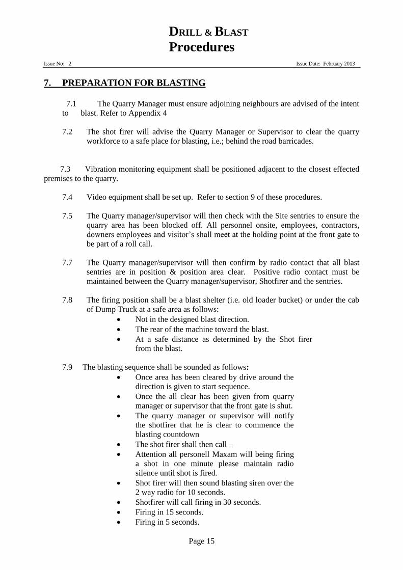
7. PREPARATION FOR BLASTING
7.1 The Quarry Manager must ensure adjoining neighbours are advised of the intent
to blast. Refer to Appendix 4
7.2 The shot firer will advise the Quarry Manager or Supervisor to clear the quarry
workforce to a safe place for blasting, i.e.; behind the road barricades.
7.3 Vibration monitoring equipment shall be positioned adjacent to the closest effected
premises to the quarry.
7.4 Video equipment shall be set up. Refer to section 9 of these procedures.
7.5 The Quarry manager/supervisor will then check with the Site sentries to ensure the
quarry area has been blocked off. All personnel onsite, employees, contractors,
downers employees and visitor’s shall meet at the holding point at the front gate to
be part of a roll call.
7.7 The Quarry manager/supervisor will then confirm by radio contact that all blast
sentries are in position & position area clear. Positive radio contact must be
maintained between the Quarry manager/supervisor, Shotfirer and the sentries.
7.8 The firing position shall be a blast shelter (i.e. old loader bucket) or under the cab
of Dump Truck at a safe area as follows:
Not in the designed blast direction.
The rear of the machine toward the blast.
At a safe distance as determined by the Shot firer
from the blast.
7.9 The blasting sequence shall be sounded as follows:
Once area has been cleared by drive around the
direction is given to start sequence.
Once the all clear has been given from quarry
manager or supervisor that the front gate is shut.
The quarry manager or supervisor will notify
the shotfirer that he is clear to commence the
blasting countdown
The shot firer shall then call –
Attention all personell Maxam will being firing
a shot in one minute please maintain radio
silence until shot is fired.
Shot firer will then sound blasting siren over the
2 way radio for 10 seconds.
Shotfirer will call firing in 30 seconds.
Firing in 15 seconds.
Firing in 5 seconds.
DRILL & BLAST
Procedures
Issue No: 2 Issue Date: February 2013
Page 16
Firing shot signal firing (signal shall be given
over the radio).
At which time the shot may be initiated by the
shotfirer if it is safe to do so,
Providing the shot has gone of the clear roads
will be given.
If the all clear has not been given to the Quarry
Manager or Supervisor 10 minutes after
detonation the Quarry Manager/ Supervisor will
try to contact by radio. If no response Quarry
Manager/Supervisor will proceed to the
destination point to inspect.

DRILL & BLAST
Procedures
Issue No: 2 Issue Date: February 2013
Page 17
7. PREPARATION FOR BLASTING (Cont’d)
7.11 The shot firer shall wait for a suitable time period after the shot has been fired before
checking the shot.
7.12 The shot firer will then examine the blast checking for any tell tail signs indicating
a misfire. If inspection of the blast is satisfactory, the “ALL CLEAR’ signal shall be
given over the radio
7.13 The Drilling and Blasting Report and post shot inspection shall be completed after
firing the blast.
7.14 If during the course of loading the shot any breakdown or other instance occurs which
will delay the shot to a point that it is not practical to initiate during that day, the Shotfirer in
conjunction with the Quarry Manager shall ensure the following actions occur:
The tie up does not occur.
All down lines shall be secured to prevent
slumping and then covered.
All explosives are returned to the appropriate
magazine overnight.
Evacuate the blast area ensuring signs and
barricades remain in place to prevent vehicular
access to the blast area.
The Quarry Manager will organise a security
guard who shall remain with the shot overnight to
ensure the shot is not interfered with.
At the commencement of the second day the
whole shot is to be inspected by the Shotfirer for
completeness of the previous days charging.
This process will occur in conjunction with Maxam
procedure 4.3-01 –Sleeping Shots will apply which includes –
Barricades and signage
Liscensed and competent security guards
Name and contact number of MAXAM
representative
Safety procedure for security guard
7.15
In the event of a pending electrical storm that may develop during loading the shot
Maxam procedure 3.02.0 will apply. This procedure includes –
Responsibilities of Business unit manger and Shotfirer
Method / procedure for detection and action on lightening activity
Action required when lightening activity is detected
Other activity
DRILL & BLAST
Procedures
Issue No: 2 Issue Date: February 2013
Page 18
7.16 In the event of an explosive vehicle breakdown MAXAM procedure 3.03.0 will
apply
8. MISFIRES
8.1 If there has been a misfire, the Shotfirer shall inform the Quarry Manager and take
all necessary steps to ensure that all personnel are prevented from entering the blast
danger area. Only those personnel approved by the Quarry Manager to deal with
the misfire shall be allowed to enter the blast area.
8.2 It is the responsibility of the Shotfirer to deal with misfires strictly in accordance
with Section 8 of Australian Standard 2187.2 - 1993 including advising the NSW
I&I Department of mines rep, John Norcott -0447 629 973 and energy explosives
inspectorate. Refer to Misfire Procedures in Appendix 3.
8.3 In the event of a misfire MAXAM PROCEDURE 3-01-2 will apply in
conjunction with HOLCIM site and business SHE requirements. This procedure
includes
Significant safety issues
Classification of misfires
Method – Legislative requirements and standards for dealing with misfires
Responsibilities of shotfirer and Business manager
Misfire handling procedures
Misfire or suspected misfire discovered at time of post shot inspection
Explosives uncovered during excavation
Dealing with misfired explosive charge
8.4 If there is no chance of the holes being recovered, the suspected area will be
marked out and photographed to clearly define the unsafe area from fixed marker
points. All personal in the Quarry will be made aware of the danger area. .
9. ENVIRONMENTAL and BLAST MONITORING
Blasting Limits, Video Taping, Monitoring and Observation of Blast
9.1 All Drilling and Blasting shall be designed to limit the impact on the environment
& on surrounding property owners. To this end blasting limits are set and shall not
exceed the following at the nearest effected residence,
Ground vibration 10mm/sec
Overpressure 115dB
9.2 During the firing of a blast no person shall be allowed to be located directly in front
of any shot face.

DRILL & BLAST
Procedures
Issue No: 2 Issue Date: February 2013
Page 19
9.2 Videotaping and/or monitoring which is conducted directly in front of any shot face
will be carried out using a tripod mount for the camera. No employee may remain
with the video camera during the firing of the blast.
9.3 Observation of any blast may only be conducted from a location authorised by the
Quarry Manager or Shot firer, these locations will be outside the shot demarcation
zones.
DRILL & BLAST
Procedures
Issue No: 2 Issue Date: February 2013
Page 20
APPENDIX 1
DRILLING PLAN
Submitted by Maxam

DRILL & BLAST
Procedures
Issue No: 2 Issue Date: February 2013
Page 21
APPENDIX 2
BLASTING
COMMUNICATION
PLAN
DRILL & BLAST
Procedures
Issue No: 2 Issue Date: February 2013
Page 22
BLASTING COMMUNICATION PLAN
A risk assessment ( refer to Appendix 5) shall be completed prior to loading a shot.
A brief toolbox talk with the Quarry Manager/Supervisor, shot firer, & sentries will take
place. This is also to involve any other personnel within the cordon or responsible for
establishing the safety cordon established for the shot.
The toolbox meeting will outline clearly what steps to take place to fire shot & all
personnel to repeat back instructions to shot firer.
Radio contact will be maintained via UHF radio channel 20 throughout the shot firing
sequence.
Responsibilities
Shot firer
The shot firer will be responsible for initiating the blast and determining the status of the shot
after initiation. The shot firer will assume full control of the shot and blast area and all decisions
made within consultation with the Quarry Manager/ Supervisor.
The shot firer shall then call –
Attention all personell Maxam will being firing
a shot in one minute please maintain radio
silence until shot is fired.
Shot firer will then sound blasting siren over the
2 way radio for 10 seconds.
Shotfirer will call firing in 30 seconds.
Firing in 15 seconds.
Firing in 5 seconds.
Firing shot signal firing (signal shall be given
over the radio).
At which time the shot may be initiated by the
shotfirer if it is safe to do so,
Providing the shot has gone of the clear roads
will be given.
The shot firer shall wait until dust & fumes has sufficiently cleared or up to 5mins
after the shot has been fired before checking the shot.
The shot firer shall inspect the shot checking for any misfires, when the shot has
been inspected confirming complete initiation the All Clear shall be given to the
Quarry Manager/Supervisor via UHF radio 20, so as to allow people & equipment
back into the area.
DRILL & BLAST
Procedures
Issue No: 2 Issue Date: February 2013
Page 23
Quarry Manager/Supervisor
The Quarry Manager/ Supervisor shall ensure that the security cordon around the shot and blast
area is secure and that no encroachment of this area occurs.
Procedure
The Quarry Manager/Supervisor shall ensure that the quarry/pit is cleared &
all staff and contractors are at the front gate muster point.
The Quarry Manager/Supervisor shall be in a position giving them a clear
vision of the shot, shot firer & roads leading into the quarry whilst being
situated so as to be at a safe distance from the front of the shot.
The Quarry Manager/Supervisor shall make UHF radio 20 contact with all
sentries to confirm it is safe to fire shot.
The Quarry Manager/Supervisor shall make UHF radio 20 contact with the
shot firer instructing the shot can be fired.
APPENDIX 3
MISFIRES
PROCEDURES
SHE Guideline Attachment 3.18C
DRILL & BLAST
Procedures
Issue No: 2 Issue Date: February 2013
Page 24
Attachment 3.18C
SHE Guideline 3.18 © HOLCIM Australia Pty Limited July 2008
TREATMENT OF MISFIRES
All identified misfires shall be made safe. The manner in which a particular misfire is to
be treated will vary.
Waiting intervals
Where explosive hazards are the only hazards present, and other hazards, such as
lingering dust and fumes, are not present, the following minimum waiting shall be
observed (Note: Where other hazards are present, for example, lingering dust and
fumes, a longer waiting time may be needed).
a) With the exception of safety fuse initiation, the minimum waiting interval is 5
minutes.
b) Where a charge or detonator that is intended to be directly initiated by safety
fuse is identified as having failed to have been initiated, no person is to approach
the misfire until an interval of 30 minutes has elapsed.
Sentries and warning signs
Appropriate sentries and warning signs shall be used to ensure that personnel are kept
clear of misfires. If a misfire needs to be left overnight then it must be watched over by
a competent person.
Treatment
Options for the treatment of misfire(s) include, but are not limited to, the following:
a) Refiring.
NOTES:
1) If lead wires are protruding from a blasthole, they should be shortcircuited
and coiled into the blasthole collar until refiring procedures are
implemented.
2) It may be necessary to increase the size of the exclusion zone.
3) Refiring should only be done after taking into account remaining
protection systems to minimize environmental and safety impacts.
b) Removal of the stemming (see section below) followed by repriming, restemming
and in itiation.
c) Removal of the explosive from the blasthole(s) by flushing the blasthole with
water, or water and air, after any stemming material has been removed.
NOTE: Environmental impacts should be considered and addressed before
explosive products are flushed.
d) Mechanical or manual removal of the explosive.
e) Drilling, charging and initiating a new blasthole in the vicinity of the misfire(s)
(see section below).
After treating the misfire(s), work shall not resume at that location until the shotfirer or
other competent person has made a thorough search for any explosive from the misfired
charge. Recovered explosive shall be disposed of in a suitable and safe manner by a
competent person. No person shall leave unguarded, abandon, discard or otherwise
neglect to safely dispose of, or ensure the security of, any explosive recovered in the
treatment of misfires. NOTE: Some regulatory authorities require that misfires be reported to
them.
Removal of stemming.
Stemming may be removed by applying water under pressure, or a mixture of water and
compressed air, through a non-ferrous blowpipe or hose. Other methods may be
available and these may be used once a risk assessment has been made.
DRILL & BLAST
Procedures
Issue No: 2 Issue Date: February 2013
Page 25
NOTES:
1) The use of compressed air alone is discouraged. Where it is used, special
precautions should be taken to minimize the dangers from static electricity and
impact.
2) Where water under pressure or compressed air is not available, the stemming may
be sludged out by the use of water and a tamping rod.
3) During stemming removal, detonator and explosive are susceptible to detonation.
4) Consideration should be given to the diameter of the blowpipe in relation to the
blasthole to allow free-flow of the materials being removed. This is to ensure that
there is no excessive pressure build -up in the blasthole.
Firing of a new hole in vicinity
The technique of firing a new hole in the vicinity of a misfire shall not occur without the
authority of the relevant legislative authority and the National Safety Manager. Before
any action, photographs should be taken of the area.
Where a hole has been previously bulled, the relieving hole method shall not be used. If
it is not possible or practicable to treat the misfire(s) by other methods, then a relieving
blasthole may be drilled as parallel as possible to the original blasthole, then charged
and fired. Before any relieving hole is drilled it shall be established that the drill will not
contact explosives. To complete this operation the following can be effective, but is
subject to other controls determined by risk analysis:
a) Refer to the blast plan to identify details of the misfired blasthole(s), (e.g.,
depth, deviation, orientation).
b) To prevent drilling into a misfire, clearly mark the hole and effectively block the
collar of the misfired blasthole (e.g., by the insertion of a wooden plug).
c) Drill the relieving blasthole at a distance which is sufficient to prevent any part of
the drill string from entering any part of the misfired blasthole.
NOTE: Where practicable, a remote operated drill rig should be used to minimize the risk
of injury to persons. With larger and longer holes, the distance between the misfired
hole and the relieving hole shall be increased as circumstances warrant.
References
This document was prepared from Australian Standard “AS2187.2-2006 Explosives –
Storage and use, Part 2: Use of explosives”.

DRILL & BLAST
Procedures
Issue No: 2 Issue Date: February 2013
Page 26
APPENDIX 4
NEIGHBOURS
CONTACT Jandra Neighbouring Properties/Residents
Name Lot DP Address Phone Comments
Helen Barnes &
Lynda Pykett 1 622594 136 Spicers Rd,
Rainbow Flat 6553 6048
Chris Lowe
1 1053482 19 Henderson St,
Gloucestor 6558 2051
Ken & Valerie
Taylor 2 622594 152 Spicers Rd,
Rainbow Flat 6553 6433
Caroline Begg
3 622594 155 Spicers Rd,
Rainbow Flat 6553 6289
Previous concerns were blasting/vibration.
Original objector
David Loveday
4 790058
15418 Pacific
H’way, Possum
Brush
6553 6102
0403 198 445
Jim Smith
4 753146 15174 Pacific H’way
Possum Brush 6554 3137
Also Lot DP1053482
Mark & Marina
Mowbray 5 790058 117 Winmurra Dr,
Rainbow Flat 6553 6294
Previous concerns were
visual & blasting/ vibration.
Mikaza Pty Ltd
Robert &
Sharon 5 790059
15165 Pacific
H’way, Possum
Brush
0404 492 450
Kim Jeffers
6 790056
15215 Pacific
H’Way
Possum Brush
6554 3181
Kimberly
Rigney 6 250607 1677 The Lakes
Way, Rainbow Flat
6553 6080
0409 101 543
Previous concerns were visual & blasting/
vibration.
Leslie Neville
7 250607 112 Spicers Rd,
Rainbow Flat 0409 120 398

DRILL & BLAST
Procedures
Issue No: 2 Issue Date: February 2013
Page 27
Graham Dubos 7&16 790056
Pacific H’way,
Failford 6554 3050
Mark & Marina
Mowbray 5 790058 117 Winmurra Dr,
Rainbow Flat 6553 6294
Previous concerns were visual & blasting/
vibration.

DRILL & BLAST
Procedures
Issue No: 2 Issue Date: February 2013
Page 28
APPENDIX 5
Disposal of
Explosives SHE GUIDELINE ATTACHMENT 3.18D
Attachment 3.18D
SHE Guideline 3.18D © HOLCIM Australia Pty Limited July 2008
Disposal of Explosives
Explosives which are surplus or are considered unsafe for transport, storage or use shall
be destroyed or removed by the supplier. Persons intending to dispose of defective
explosives shall seek advice from the manufacturer where it is available. Where such
advice is not available, destruction of these explosives shall be in accordance with this
document.
Wherever practical the supplier should remove the explosives for destruction.
Records
Records shall be kept of quantities and types of explosive destroyed, and the destruction
methods employed.
Residues
The residue from explosives destroyed by burning may be poisonous to livestock and
wildlife. It shall be buried or otherwise disposed of in accordance with applicable
environmental legislation.
Method of disposal
Explosives shall not be abandoned, thrown away, buried, discarded or placed with
garbage. Before commencing to destroy explosives, an exclusion zone shall be
established and made secure. Destruction of explosives shall be carried out under the
control of a competent person.
NOTES:
1) For guidance on whether to destroy explosives not mentioned in this section, the
manufacturer, supplier or the regulatory authority should be consulted.
2) Explosives that show evidence of serious exudation are likely to be unstable.
3) When serious exudation is a problem or if large quantities of explosives are to be
destroyed, the appropriate regulatory authority and the supplier of the explosives
should be contacted.
Explosives other than detonators
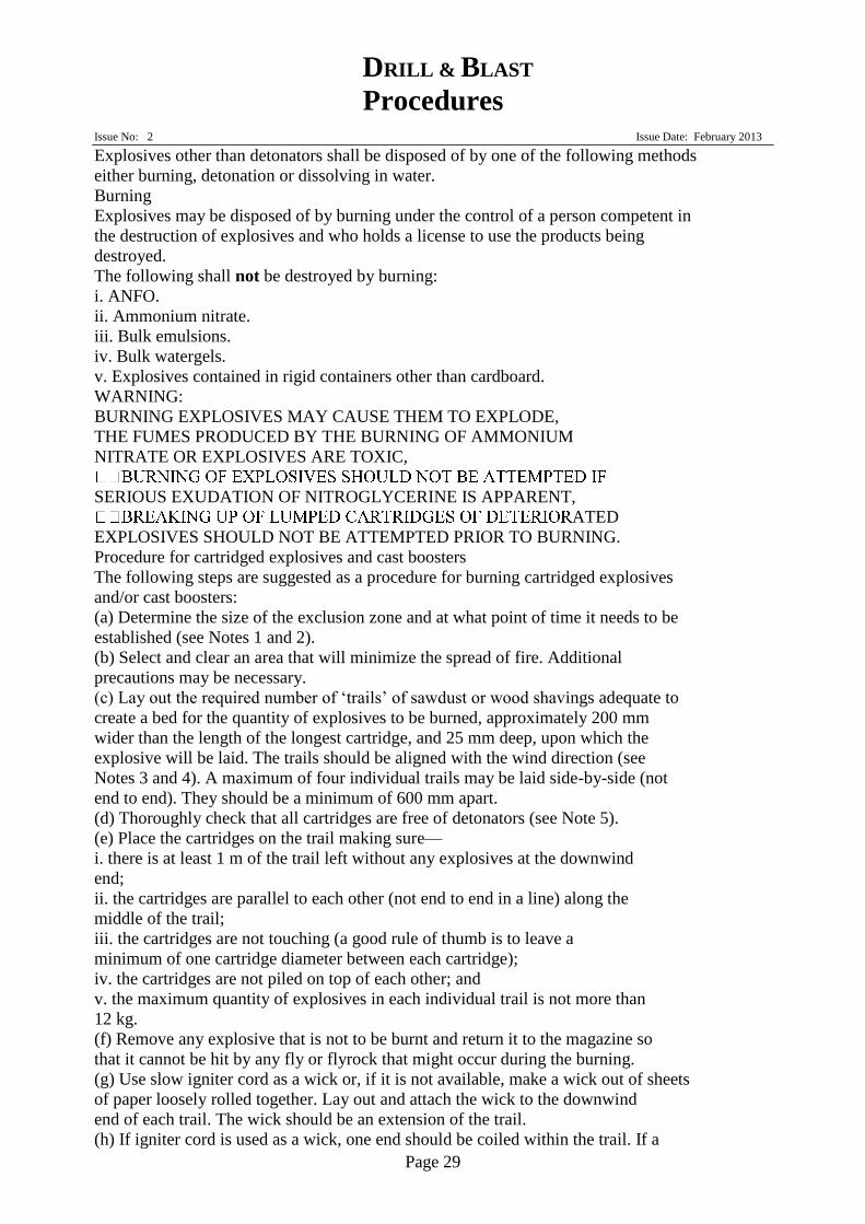
DRILL & BLAST
Procedures
Issue No: 2 Issue Date: February 2013
Page 29
Explosives other than detonators shall be disposed of by one of the following methods
either burning, detonation or dissolving in water.
Burning
Explosives may be disposed of by burning under the control of a person competent in
the destruction of explosives and who holds a license to use the products being
destroyed.
The following shall not be destroyed by burning:
i. ANFO.
ii. Ammonium nitrate.
iii. Bulk emulsions.
iv. Bulk watergels.
v. Explosives contained in rigid containers other than cardboard.
WARNING:
BURNING EXPLOSIVES MAY CAUSE THEM TO EXPLODE,
THE FUMES PRODUCED BY THE BURNING OF AMMONIUM
NITRATE OR EXPLOSIVES ARE TOXIC,
SERIOUS EXUDATION OF NITROGLYCERINE IS APPARENT,
ATED
EXPLOSIVES SHOULD NOT BE ATTEMPTED PRIOR TO BURNING.
Procedure for cartridged explosives and cast boosters
The following steps are suggested as a procedure for burning cartridged explosives
and/or cast boosters:
(a) Determine the size of the exclusion zone and at what point of time it needs to be
established (see Notes 1 and 2).
(b) Select and clear an area that will minimize the spread of fire. Additional
precautions may be necessary.
(c) Lay out the required number of ‘trails’ of sawdust or wood shavings adequate to
create a bed for the quantity of explosives to be burned, approximately 200 mm
wider than the length of the longest cartridge, and 25 mm deep, upon which the
explosive will be laid. The trails should be aligned with the wind direction (see
Notes 3 and 4). A maximum of four individual trails may be laid side-by-side (not
end to end). They should be a minimum of 600 mm apart.
(d) Thoroughly check that all cartridges are free of detonators (see Note 5).
(e) Place the cartridges on the trail making sure—
i. there is at least 1 m of the trail left without any explosives at the downwind
end;
ii. the cartridges are parallel to each other (not end to end in a line) along the
middle of the trail;
iii. the cartridges are not touching (a good rule of thumb is to leave a
minimum of one cartridge diameter between each cartridge);
iv. the cartridges are not piled on top of each other; and
v. the maximum quantity of explosives in each individual trail is not more than
12 kg.
(f) Remove any explosive that is not to be burnt and return it to the magazine so
that it cannot be hit by any fly or flyrock that might occur during the burning.
(g) Use slow igniter cord as a wick or, if it is not available, make a wick out of sheets
of paper loosely rolled together. Lay out and attach the wick to the downwind
end of each trail. The wick should be an extension of the trail.
(h) If igniter cord is used as a wick, one end should be coiled within the trail. If a
DRILL & BLAST
Procedures
Issue No: 2 Issue Date: February 2013
Page 30
paper wick is used, ensure that at least 1 m of it is in contact with the trail. The
wick should be secured so that it cannot be accidentally dislodged by the wind
after lighting.
(i) The length of the wick should be sufficient to allow the person(s) lighting it to
retire to the predetermined safe place after it has been lit.
(j) Thoroughly wet the trail and the explosives (and the paper wick) with kerosene
or diesel (never petrol or other highly flammable liquid) (see Note 6).
(k) Implement the exclusion zone if not already established.
(l) Implement the predetermined safety procedures, light the wick and retire to the
predetermined safe place (see Note 7).
(m)Do not return to the site for at least 15 minutes after the burning has apparently
finished.
(n) If the fire goes out before any trail has finished burning, do not approach for at
least 15 minutes after all trace of fire has apparently gone.
(o) Do not add more kerosene or diesel while there is any potential for re-ignition
during application.
NOTES:
1) This may need to be during the delivery or preparation stage of the work. The
condition of the explosives and the quantity to be burned can influence the
decision making process.
2) The size of the exclusion zone should be large enough to allow for the possibility
of an explosion occurring during the burn.
3) The trail(s) should be aligned such that the flame from the trail and the burning
explosives will blow away from the unburned explosives as detonation is more
likely to occur if the explosives are preheated by the flame.
4) Some emulsion and water-gel explosives are difficult to burn and may require
additional fuel. The manufacturer or supplier should be contacted if large
quantities of these explosives are to be destroyed.
5) Puncture marks in the side or the end of a cartridge can indicate the possible
presence of a detonator.
6) The use of excess fuel will only soak into the ground and unnecessarily prolong
burning that might not include explosives.
7) If more than one wick is to be lit, it is recommended that either the wicks are
joined or a multiple fuse lighter is used.
Procedure for Detonating cord
Detonating cord should not be burnt on a reel or spool but cut into lengths, or loosely
coiled, and placed on top of the trail(s) as for cartridged explosives. It should be burnt
in lots not greater than the equivalent of two 10 g/m reels at a time or a maximum of
1000 m, whichever is the lesser. Extreme care should be taken to ensure that there are
no detonators or detonating delay devices attached to any part of the detonating cord.
Procedure for Safety fuse
Other than a possible fire or pollution hazard, there is little danger with safety fuse,
provided that care is taken to ensure that it is free of detonators. It may be destroyed
by burning on an open fire.
Procedure for Ignitor cord
When burning igniter cord it should be completely uncoiled from its spool. It will not
need fuel to assist in the burning process and an area well cleared of flammable material
is necessary as it can whip violently during burning. A length of safety fuse is
recommended as a wick as it will allow the person lighting it to be well clear prior to the
igniter cord commencing to burn.
DRILL & BLAST
Procedures
Issue No: 2 Issue Date: February 2013
Page 31
Detonation
Explosives may be disposed of by detonation, provided that a fresh priming charge is
used and no detonators are inserted into deteriorated or previously charged explosives.
Explosives shall not be detonated on stony ground, in a shallow hole in such ground, or
on an area where debris is likely to become missiles (Note: missile damage can be
expected over an extensive distance). The extent of the spread of such fly or flyrock
will be proportional to the quantity of explosives being destroyed and the nature of the
ground and debris. These factors should be considered when determining the exclusion
zone. For this reason, explosives should be detonated in sand or earth free from stones.
Dig a hole of at least 600mm depth. Place items to be destroyed in a group in the hole.
Place a primer on top of them in contact with all items. Cover with paper and back fill
the hole with fine material (e.g. crusher dust, sand, soil, etc). Fire the primer, and then
search for unexploded products.
Dissolving in water
Small quantities of water-soluble explosives (e.g. ANFO) may be destroyed by immersion
in buckets or drums of water. Alternatively, water-soluble explosives may be spread on
the ground and watered in. The resulting fluids will not be allowed to enter a drain or
watercourse.
Detonators
Small quantities of detonators may be disposed of by detonation.
Where there is serious deterioration of detonators or large quantities of detonators need
to be destroyed, the regulatory authority and the supplier shall be consulted.
Detonators maybe inserted into a primer cartridge and disposed of in a blast hole. They
will never be dropped into blast holes as single items.
An alternative is to dig a hole 600mm deep in fine soil or crusher dust. Secure the
detonators together around a primer cartridge and back fill. Fire the primer, and then
search for unexploded products.
Other explosives
For methods of destroying explosives not mentioned above, the manufacturer shall be
consulted.
References
This document was prepared from Australian Standard “AS2187.2-2006 Explosives –
Storage and use, Part 2: Use of explosives”.
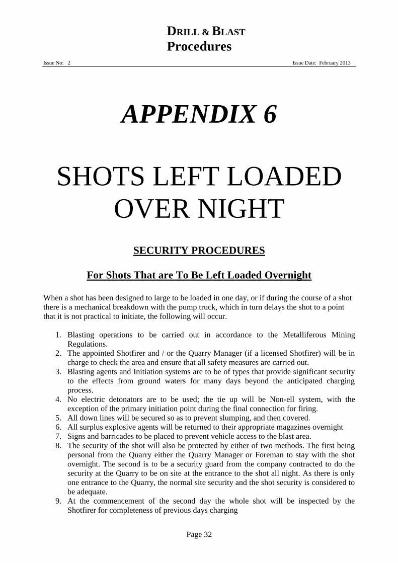
DRILL & BLAST
Procedures
Issue No: 2 Issue Date: February 2013
Page 32
APPENDIX 6
SHOTS LEFT LOADED
OVER NIGHT
SECURITY PROCEDURES
For Shots That are To Be Left Loaded Overnight
When a shot has been designed to large to be loaded in one day, or if during the course of a shot
there is a mechanical breakdown with the pump truck, which in turn delays the shot to a point
that it is not practical to initiate, the following will occur.
1. Blasting operations to be carried out in accordance to the Metalliferous Mining
Regulations.
2. The appointed Shotfirer and / or the Quarry Manager (if a licensed Shotfirer) will be in
charge to check the area and ensure that all safety measures are carried out.
3. Blasting agents and Initiation systems are to be of types that provide significant security
to the effects from ground waters for many days beyond the anticipated charging
process.
4. No electric detonators are to be used; the tie up will be Non-ell system, with the
exception of the primary initiation point during the final connection for firing.
5. All down lines will be secured so as to prevent slumping, and then covered.
6. All surplus explosive agents will be returned to their appropriate magazines overnight
7. Signs and barricades to be placed to prevent vehicle access to the blast area.
8. The security of the shot will also be protected by either of two methods. The first being
personal from the Quarry either the Quarry Manager or Foreman to stay with the shot
overnight. The second is to be a security guard from the company contracted to do the
security at the Quarry to be on site at the entrance to the shot all night. As there is only
one entrance to the Quarry, the normal site security and the shot security is considered to
be adequate.
9. At the commencement of the second day the whole shot will be inspected by the
Shotfirer for completeness of previous days charging
DRILL & BLAST
Procedures
Issue No: 2 Issue Date: February 2013
Page 33
APPENDIX 7
SHOT LOADING
PROCEDURES
Shot Loading Procedures
For Jandra Quarry
Steps:
1. A licensed Shotfirer must be present on all shots being loaded.
2. Area to be sign posted to identify loading in progress and access to authorised personnel only.
3. Shot design is to be set out by the Quarry Manager or his Appointee, or in conjunction with
an external technical service agent, ensuring proper alert device for face edge hazard. (Eg.
Bunding – flagging tape). A minimum of one metre set back from edge is required unless
impractical, in this case a physical restraint will be required. Always work facing the edge;
never turn your back to face.
4. Should weather conditions give the risk of lightning strikes the shot will be postponed and
access to the shot restricted with signage & barriers. No one will return to the shot until the
site Manager & Shot Fire deem it safe to do so.
5. When handling Dets on the shot it is of this Quarry’s safety Team opinion that Hard Hats will
not be worn unless immediately under a face, this is to eliminate the chance of a hat falling
onto a Det and causing initiation. Potential extraneous electrical currents eg, mobile phones
and radios shall be turned of and eliminated before any electrical det is brought onto the shot.
Electric dets shall be tested off the shot prior to connection.
6. Collect required amount of Accessaries as per design from Magazine’s in blast truck, with
Dets Separated to HE Explosives by insulated Containers, or carried separately and proceed
to shot.
7. Remove all bags or cones from holes and place bottom primer’s, 400 Gram with required
length down lines ready for bulk loading.
8. Leave required rows free of primers to allow for Bulk Tanker to travel down for charging
with using a spotter for guidance. Only rows with no products to be driven over.
9. Shot designer to work in conjunction with truck to control charging depths.
10.Check and follow Procedures for priming holes, and other risks connected with both loading
and firing shots.
11.Shot Firer or his appointee will top prime the holes with 150 Gram boosters were possible
and verify loading height.
DRILL & BLAST
Procedures
Issue No: 2 Issue Date: February 2013
Page 34
12.Once holes have been topped primed, 14mm aggregate is used to stem holes, should any
hole not take the required stemming amount, a loader bucket of dust is to be placed over that
hole to eliminate the chance of ejection.
13.Tying in of shot with Non Electric Dets as per the Shot Firer’s designed sequence can begin
as soon as rows are clear, but only by a qualified Shot Firer or the Managers Authorised
appointee.
14.Shot area will then be cleared of all rubbish ( eg: empty boxes, drill bits broken rods etc)
ready for firing. Then Blasting Procedures will follow 15.Non- electric lead line detonator will be connected to the initiation point when area is
completely cleared and safe for firing it will be joined to the initiation point by the Shotfirer
only.
APPENDIX 8
THEFT or LOSS of
EXPLOSIVES
Theft of explosive or any unaccountable stock shortages shall be reported
appropriately. Explosives shall be regarded as accountable items and any
evidence of attempted forced entry to, or theft of explosives from, a magazine or
an unaccountable stock discrepancy shall be immediately reported in accordance
with the relevant legislation, to the regulatory authority and the police. The
records shall be readily available to permit the determination of the type and
quantity of missing explosive.
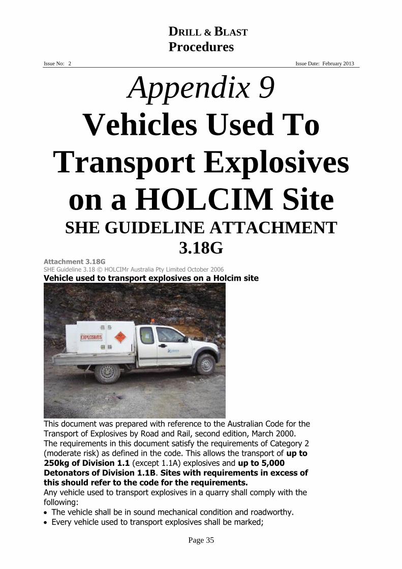
DRILL & BLAST
Procedures
Issue No: 2 Issue Date: February 2013
Page 35
Appendix 9
Vehicles Used To
Transport Explosives
on a HOLCIM Site SHE GUIDELINE ATTACHMENT
3.18G Attachment 3.18G SHE Guideline 3.18 © HOLCIMr Australia Pty Limited October 2006
Vehicle used to transport explosives on a Holcim site
This document was prepared with reference to the Australian Code for the Transport of Explosives by Road and Rail, second edition, March 2000. The requirements in this document satisfy the requirements of Category 2 (moderate risk) as defined in the code. This allows the transport of up to 250kg of Division 1.1 (except 1.1A) explosives and up to 5,000 Detonators of Division 1.1B. Sites with requirements in excess of this should refer to the code for the requirements. Any vehicle used to transport explosives in a quarry shall comply with the following:
The vehicle shall be in sound mechanical condition and roadworthy.
Every vehicle used to transport explosives shall be marked;

DRILL & BLAST
Procedures
Issue No: 2 Issue Date: February 2013
Page 36
At the front, rear and on both sides with the words “EXPLOSIVES” in red capital letters not less than 150mm high on a white background. At the front and rear with the class label for explosives. These labels shall be a minimum 250mm square and comply with Australian Standard “AS1216 Class labels for dangerous goods”.
All markings shall be removed or concealed whenever the vehicle does not have explosives on board.
The appropriate Emergency Procedure Guide shall be carried in a
pocket attached to the drivers door. Explosives shall be in a locked receptacle (complying to Attachment
3.18F Explosives receptacle) securely fixed to the vehicle.
No other dangerous goods shall be transported on the vehicle.
Shall have at least one fire extinguisher with a rating of at least 30B as
per Australian Standard “AS1850 Portable fire extinguishers— Classification, rating and performance testing” mounted in a readily accessible position using a quick release bracket.
Appendix 10
Blasting Checklist SHE GUIDELINE ATTACHEMENT
3.18H

DRILL & BLAST
Procedures
Issue No: 2 Issue Date: February 2013
Page 37
Blasting Checklist
Site
Date
Time of blast
Shotfirer
Shot number
Weather conditions
Item
Checked
1. Check blast warning signs are in place
2. Face inspected (note weaknesses, shattered ground, overhangs, jointing, etc)
3. Hole profiles reviewed and burden confirmed
4. Check drillers log
5. Design Blast (eg initiation sequence, explosives loading, stemming height, deck loading, etc)
6. Check weather forecast
7. Check explosives loading log for over charging ,etc
8. Check tie up as per design
9. Return excess explosives and detonators to the magazine
10. Notify neighbour by phone (if applicable)
11. Notify all site personnel of impending shot
12. Check blast monitoring equipment is in place (eg video, air and ground vibration)
13. Check sentries /barriers in place
14. Check all persons and machinery are clear of blasting area
15. Siren sequence
16. Initiate blast
17. Check for misfires
18. Sound all clear
Comments (eg on result of blast, incidents or complaints, proposed modification for future blasts, etc)
Signed (Shotfirer): Licence Number:

DRILL & BLAST
Procedures
Issue No: 2 Issue Date: February 2013
Page 38