z techniques for reducing gun blast noise levels: an ... · nswc tr 81-120 z techniques for...
TRANSCRIPT

NSWC TR 81-120
Z TECHNIQUES FOR REDUCING GUN BLASTNOISE LEVELS: AN EXPERIMENTAL STUDY
byLARRY L. PATERJOHN W. SHEACombat Systems Department
APRIL 1981
DTTCApproved for pubhc release; distribution unlimited.
" MAR 2,3 1982
NAVAL SURFACE WEAPONS CENTER
,Dahqren, Virginia 22443 Si;ver Spring, Maryland 20910

UNCLASS IFI EDSECURITY CLASSIFICATION OF THIS PAGE (W"en Dala Entered)
/RA INSTRUCTIONS'REPORT DOCUMENTATION PAGE RE COMTRETIORM
____________________________________ BEFORECOMPLETINGFORMI. REPORT NUMBER 2, GOVT ACCESSION NO. 3. RECIPIENT'S CATALOG NUMBER
NSWC TR 81-120 Allj/14 2 __
4. TITLE (&nd Subtitle) S. TYPE OF REPORT & PERIOD COVERED
TECHNIQUES FOR REDUCING GUN FinalBLAST NOISE LEVELS: ANEXPERIMENTAL STUDY S. PERFORMING ORO, REPORT NUMBER
7. AUTHOR(s) S. CONTRACT OR GRANT NUMUER(e)
Larry L. PaterJohn W. Shea
9. PERFORMING ORGANIZATION NAME AND AOORESS 10. PROGRAM ELEMENT, PROJECT, TASK
Naval Surface Weapons Center (Code N43) AREA & WORK UNIT NUMBERS
Dahlgren, Virginia 22448 63657N, 63721N
I'I. CONTROLLING OFFICE NAME AND ADDRESS 12. REPORT DATE
Naval Sea Systems Command April 1981Code NAVSEA 62Y1 13. NUMBER OF PAGES
Washington, DC 20360 6414. MONITORING AGENCY NAME & ADORESS(If different (ram Controllinl Office) 15. SECURITY CLASS. (of thie report)
UNCLASSIFIEDISa. DECL ASSI F.ICATION/DOWNGRADING
SCHEDULE
IS. DISTRIBUTION STATEMENT (of thls Report)
Approved for public release; distribution unlimited.
17. DISTRIBUTION STATEMENT (of the abstract entered In Block 20, If different from Report)
IS. SUPPLEMENTARY NOTES
19. KEY WORDS (Continue on reverse aide if neceeesay end Identify by block nunubet)
Gun BlastCommunity NoiseNoise Reduction
"20. ABSTRACT (Continue on revere ide If neceseary ad Identify by block nugmber)
Several techniques for reducing gun muzzle blast noise level were in-vestigated experimentally to determine potential effectiveness and utilityfor existing major-caliber guns. Techniques explored included muzzle brakes,conical muzzle devices, baffle-type silencers, water spray, and aqueous foam.
DO I FW'ANM 1473 EDITION OF I NOV 6S IS OBSOLETE UNCLASSIFIEDS/N 0102"014" 6601
SECURITY CLASSIFICATION OF THIS PAGE ({When Data BEntered)

UNCLASSIFIED-IJ4-,IR!Y CLASSIFICATION OF THIS PAGE(Whom DaCm Enterad)
lxl
UNC!,ASSIFIED
SECURITY CLASSIFICATION OF THIS PAGCE(ften Data Entered)

FOREWORD
This report was prepared as part of a developmental program to determine
methods of reducing noise levels due to Naval weapons, particularly large guns,
during training and testing operations. Early work was funded by the Naval
Science Assistance Program (NSAP) at the request of COMTHIRDFLT and by the Navy
Independent Research program. The majority of work was carried out under the
Gun Blast Effects program, NAVSEATASK 653/497/004-1-S0956.
This report was reviewed and approved by F. H. Maillie and J. F. Horton of
the Systems Safety Division of the Combat Systems Department.
Released by:
THOMAS A. CLARE, HeadCombat Systems Department
Accession ForNTIS GRA&I
DTIC TAl3Uinmnn mc d LJustificrition -
By. -______
Dist r 1-i t on/
Availability CodosJAvail and/or
Dist Special
Liq
DTICG
/ oly

CONTENTS
Page
ABBREVIATIONS AND ACRONYMS ................... ....................... vii
INTRODUCTION .......................... .............................. 1Objective ........................ ............................. 1Background ................ ............................. .. ... 1Project Scope ...................... ........................... 3
BASELINE: BARE MUZZLE .................... ......................... 4
PROCEDURES AND APPARATUS .................... ........................ 9
MUZZLE BRAKE .......................... .............................. 12
CONICAL MUZZLE DEVICES ............... ......................... .... 14
BLAST REDUCER MUZZLE DEVICES ............. ...................... ... 22
WATER SPRAY ................... ............................... .... 26
FOAM ...................... .................................. .... 33
SUMMARY OF CONCLUSIONS ............... ......................... .... 39
REFERENCES .................... ............................... .... 44
DISTRIBUTION
ILLUSTRATIONS
Figure
1 Bare Muzzle Near-Field Peak Overpressure (psi) ...... ........ 52 Bare Muzzle Near-Field Peak Sound Pressure Level (dB) ......... 63 Bare Muzzle Near-Field Directivity (dB) re 1800 .... ........ 74 Muzzle Blast Directivity ............... ................... 85 7.62-mm Rifles ............................................... 106 Change in Muzzle Blast Far-Field PSPL Due to
Muzzle Brake ............................................. 157 Change in PSPL Due to 100 Conical Muzzle Device .......... ... 178 Change in Muzzle Blast Far-Field PSPL Due to 100
Conical Muzzle Device .......... .................... ... 20
v
Preceding Page Blank

ILLUSTRATIONS (Cont'd)
Figure Page
9 Schematic Cross Section of Blast ReducerConfiguration BR-A ........... ..................... .... 23
10 Schematic Cross Section of Blast Reducer ... ........... ... 24Configuration BR-F
11 Change in Muzzle Blast Far-Field PSPL Due toBlast Reducer Muzzle Devices ........ ................ ... 29
12 Water Spray ................ .......................... .... 30
TABLES
Table
1 Muzzle Brake Far-Field PSPL Raw Data, 7.62-mm Rifle ...... ... 132 Change in Far-Field PSPL Due to Muzzle Brake, 7.62-mm Rifle 143 100 Conical Muzzle Device Far-Field PSPL Raw Data,
7.62-mm Rifle Test .... ..................... 184 Change in Far-Field PSPL Due to 100 Conical Muzzle
Device, 7.62-mm Rifle Test ............. ................. 195 Change in Far-Field PSPL Due to 100 Conical
Muzzle Device, 5"/54 Naval Gun Test .... ............. .... 216 BR-A Far-Field PSPL Raw Data ............. ................. 257 Change in Far-Field PSPL Due to Blast Reducer BR-A ...... ... 268 BR-F Far-Field PSPL Raw Data ............. ................. 279 Change in Far-Field PSPL Due to Blast Reducer BR-F ...... .. 28
10 7.62-mm Rifle Water Spray Experiment .... ............. ... 3211 40-mm Gun Water Spray Experiment ...... ............... .... 3412 7.62-mm Gun Foam Experiment ........ .................. ... 40
vi

ABBREVIATIONS AND ACRONYMS
BM Barrel Muzz]e
caliber 1.0 barrel bore diameter
dB Decibel
GPM Gallons per Minute
]lz Hertz
kn Knots
mm Millimeter
No. Number
NSAP Naval Science Assistance Prcgram
psi Pounds per square inch
PSPL Peak Sound Pressure Level
vii

INTRODUCTION
OBJECTIVE
The purpose of this project was to determine the utility and effectiveness
of several techniques for reducing gun blast far-field noise. The techniques
that were investigated are in general applicable to guns of all sizes, from
pistols and rifles to very large artillery and naval guns. Primary interest
was in procedures and/or devices suitable for use on major-caliber guns such as
the 5"/54 naval gun. It was desired that the procedures or devices be suitable
for temporary use (e.g., during training and testing operations) on existing gun
systems, without requiring extensive modification of, or causing damage to, the
gun system or platform. Only a negligible effect on projectile trajectory could
be tolerated, and impact on training and testing operations was to be minimized.
Most of the noise reduction techniques that were investigated involve the
use of some type of muzzle device. The requirement that the noise reducing
device be suitable for use on existing gun systems severely restricts the allow-
able size and weight of the device. For example, very effective silencers have
been developed for pistols and rifles, but these devices are typically of about
the same size and weight as the gun barrel, and thus are obviously not suitable
for use on major-caliber guns. Hardware size and weight restrictions were thus a
major consideration throughout the project.
BACKGROUND
There are three sources of noise associated with firing a gun. These are
the muzzle blast that occurs when the projectile uncorks the high-pressure pro-
pellant gases, the bow shock (sonic boom) of the supersonic projectile, and
projectile detonation. Projectile detonation noise can be eliminated or reduced
by using projectiles that are inert or contain only a very small spotting charge.
The projectile bow shock noise field is discussed in some detail in another1report and will be discussed only briefly here. Projectile bow shock exists in
I

only a portion of the blast field, typically within a sector of about 600 to
either side of the line of fire. Within this region, bow shock noise level at
the earth's surface varies according to a complicated dependence upon projectile
trajectory, projectile speed along the trajectory, projectile size and shape,
and atmospheric acoustic refraction. The bow shock noise may be more significant
than muzzle blast noise at some field locations, especially near the line of
fire. Noise exposure due to projectile bow shock can be minimized by stopping
the projectile at the shortest possible range. It should be noted that a muzzle
blast noise reduction technique that has no effect on the projectile velocity or
trajectory will have no effect on the projectile bow shock noise field.
Reducing muzzle blast noise is a challenging problem, since muzzle blast is
an unavoidable effect of firing a gun. One approach is to use "no-fire simula-
tion" in lieu of firing for training purposes. This technique involves training
disadvantages and requires sophisticated and expensive simulation systems, and
so may reduce but probably not eliminate gunfire for training, and would have
only limited application for testing.
Under the proviso that the gun is to actually be fired, there are basically
two approaches to reducing muzzle blast noise:
1. Redistribute the blast field energy such that noise levels are decreased
in some regions of the blast field, at the expense of increased noise levels in
other regions.
2. Remove energy from the blast wave, resulting in decreased sound levels
throughout the entire blast field.
There are several potential methods of implementing these two basic approaches.
Naturally occurring atmospheric sound refraction can be used (but not control-
led) to redistribute blast field energy. This technique can be important for all2-10
types of noise and has been extensively discussed in other reports. Methods
of implementing utilization of atmospheric refraction include field monitoring
of noise levels and ray-tracing algorithms based on meteorological sounding data.
Cognizance of atmospheric refractionfmust be a mandatory part of noise control
2

procedures for far-field explosive noise, since the phenomenon can result in
result in noise level variations of as much as 50 dB for a given source.
A blast energy redistribution technique that offers more direct control of
gun muzzle blast noise levels is utilization of muzzle blast field directivity.
Recent studies 1') have shown that muzzle blast directivity amounts to approxi-
mately 15 dB throughout the far field; i.e., the peak sound pressure level (PSPL)
and C-weighted sound exposure level at a given distance from the gun are about
15 dB higher in front of the gun than behind the gun. Thus, in some firing range
scenarios, a measure of control of noise levels can be achieved by controlling
direction of fire as well as gun location.
PROJECT SCOPE
The current project consisted of further investigation of techniques and
devices for controlling gun muzzle blast noise levels. Conical muzzle devices
and a muzzle brake were tested to determine the degree of blast redistribution
due to such devices. Blast reducers of conventional silencer design, but small
and light enough to possibly be used with existing major-caliber guns, were in-
vestigated as a method of removing energy from the blast wave. Another technique
for removing energy from the blast wave, which was investigated in a preliminary
fashion, was to introduce into the gun muzzle region some substance that would
interact with and remove energy from the blast wave during or shortly after its
formation. Substances that were tried included water spray and aqueous foam.
The effectiveness of each noise reduction technique was judged according to
the amount of reduction in PSPL that was achieved.* It is generally agreed that,
for occasional noise events, unaided human hearing cannot reliably detect dif-
ferences in PSPL smaller than about 3 dB. On the other hand, a change of 10 dB
* It should be recognized that PSPL alone is not necessarily an adequate general
description of human annoyance. 1 0 , 1 2 , 1 3 ,14,1 5 However, PSPL is a good indica-tor if duration and spectral energy distribution are not greatly changed, andoffers the advantage of being easily measured.
3

seems to correspond roughly to a factor of two change in subjective noisiness or
annoyance. Thus, any noise reduction technique that yields a change in noise
level of less than 3 dB is of little or no value in terms of reducing human
annoyance. A reduction of at least 10 dB was the goal of the present project.
BASELINE: BARE MUZZLE
The near-field peak overpressure distribution for bare muzzle guns has been
extensively documented. 16-22 Figure I shows a typical near-field peak over-17*
pressure distribution. Figure 2 shows the same blast field expressed as PSPL
in units of decibels,** and Figure 3 explicitly shows the PSPL directivity rela-
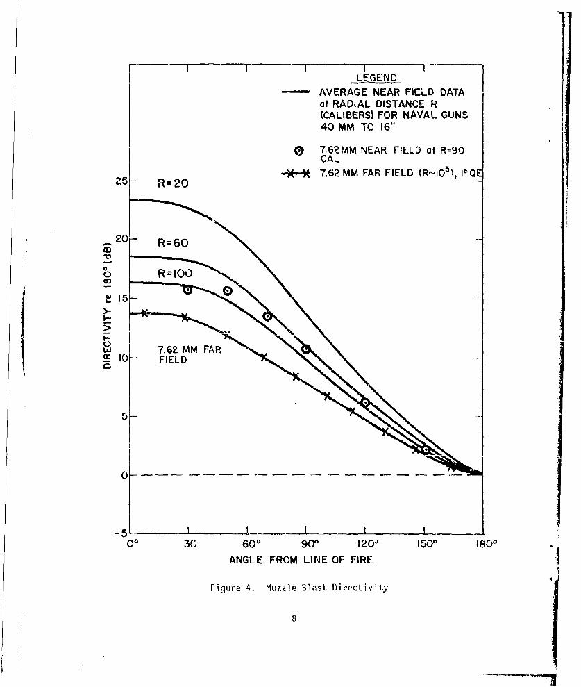
tive to 1800 from the line of fire. This same near-field directivity information
is shown in different format in Figure 4. Also shown in Figure 4 is near-field
data for the 7.62-mm rifle used to obtain most of the data presented in this
report. It can be seen that the 7.62-mm rifle near-field peak overpressure
directivity agrees quite well with that of major-caliber naval guns. The general
validity of reduced-scale investigation of near-field gun muzzle blast has been
well established.1,16,17'18,2 3
* This blast field is an average for a wide variety of naval guns. Similitudewas achieved by expressing radial distance from the gun muzzle in units ofcalibers, one caliber being equal to the gun bore diameter.
- Peak sound pressure level (PSPL, or Lpk) is a logarithmic comparison scaledefined by
Lpk =10 log 1 0 ( 1 20 log0 P
0
inunits of decibels, where P = peak overpressure and P = 20 pP = 2.9 x_yi.m 0 o. a10 psi = reference overpressure for 0 dB. Further discussion may be foundin many references, for example Reference 1 or 10 of this report.
4

00I00,4
ANGLE FROM LINE
30 OF FIREn 2_5
w-JJ
0604
i' d 5.1 600
U)
- j
N 16.1S8.2 2.2 ý.' 900
4.2
1.7/19Q3
0575i.86 a- dr
0 "- '-0.62.
0.52
0.39 j 150 °
100, --- -
1800
Figure 1. Bare Muzzle Near-Field Peak Overpressure (psi)

00
10010i79--3 ANGLE FROM LINE
/300 OF FiRE
cr,w
tJ
UZ -600
.. 1
N /I176 I72.6,19o
2090
183.56.5 !O
Figure 2. Bare Muzzle Near--Ficld Peak Sound Pressure Level (dB)
6
173.

100 1.S300 ANGLE FROM LINE
6.- OF FIRE
U."m_
"U 18.7
wi
N
60 •600
13.6
22.7
-j
N 1'905
I00 O•9---900
4I
3AA
00
1500
lot1800,
Figure 3. Bare, Muzzle Near-Field Directivity (dB) re 180' ..
7
II ILEGENDAVERAGE NEAR FIELD DATA
at RADIAL DISTANCE R(CALIBERS) FOR NAVAL GUNS40 MM TO 16"
0 7,62MM NEAR FIELD at R=90CAL
25 R2-e- 7,62 MM FAR FIELD (R-,10S5), I-FQE25- R =20
-.20- R=60ID
b R=1O00OD
0
I__II0 - FIELD
-5-
00 30 600 900 120 1500 1800
ANGLE FROM LINE OF FIRE
Figure 4. Muzzle Blast Directivity
8
Recent work '11 has shown that gun muzzle blast PSPL directivity amounts to
about 14 to 17 dB and is essentially constant for a given gun throughout the far
field.* The far-field PSPL directivity of the 7.62-mm rifle used in the present
investigation is shown in Figure 4. It has been shown' that the 7.62-mm rifle
is an adequate scale replica of major-caliber guns for purposes of reduced-scale
blast field investigation.
PROCEDURES AND APPARATUS
The noise parameter that was measured throughout the current study was peak
unweighted sound pressure level. Data acquisition was by means of Gen Rad
Model 1982 sound level meters. For measurement of PSPL, the meter control
settings used were "flat" weighting, "peak" detector, octave filter selector set
to "WTG" (broad band), and the range switch set to the appropriate decibel range.
Microphone attenuators (-10 dB) were used when PSPL exceeded 140 dB. The meters
were modified to make the PSPL value available as a constant voltage at the "DC
out" jack, output linear in decibel. This voltage was transmitted via land
lines, using a specially fabricated "line driver," from each instrumentation lo-
cation to an instrumentation van where the voltage values were sequentially and
rapidly recorded by means of a Datel Systems Model PDL-10 Data Logger. The re-
corded voltages were converted to decibel values during data reduction by means
of voltage versus decibel calibration curves previously prepared for each sound
level meter. The meters were also modified by installation of a small solenoid
used to remotely actuate (from the instrumentation van) reset of the peak and
hold circuitry. Sound level meters were calibrated before each test by means of
Gen Rad Model 1567 1000 Hz Sound Level Calibrators.
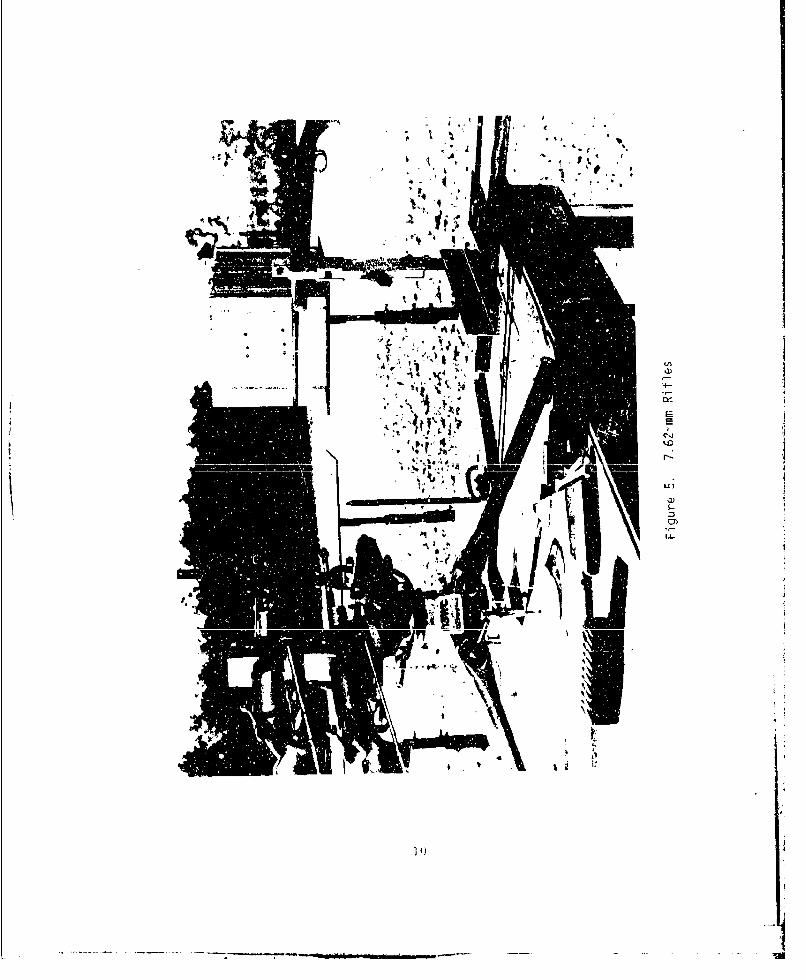
The 7.62-mm rifles used to obtain most of the data were mounted in an over-
and-under configuration on a machine gun tripod as shown in Figure 5. This
* Data have been presented for Adistances in excess of 100,000 calibers.
9
�
4- 4.P
Vt '
I
U)di
'4-
EE
* to
Ul
10 4
'S

arrangement allowed accurate and repeatable adjustments of gun train angle
(direction of fire), so that data could be obtained at various angles from the
line of fire without moving the instrumentation. Projectile bow shock was
eliminated from the blast field by means of bullet traps located a few hundred
calibers downrange from the gun muzzle.
Throughout this report the effects of the various muzzle blast noise re-
duction techniques are presented in terms of excursions of far-field PSPL from
the far-field directivity curve* shown in Figure 4. This data presentation is
meaningful since both far-field directivity and the effect of each noise reduc-
tion technique relative to the directivity curve are practically invarient
throughout the far-field, except for variations caused by atmospheric refraction.
Atmospheric refraction effects on the data were avoided to a considerable extent
by using two closely juxtaposed guns, one bare muzzle and one employing the noise
reduction technique. The guns were fired at about 10-second time intervals,
with a total of six rounds fired from each gun at each train angle of interest,
for most of the tests. The parameter of interest is the difference in noise
level for the two guns. This procedure relies on the assumption that atmospheric
propagation conditions do not vary significantly during a short time interval,
which is generally true for gross atmospheric temperature and wind structure.
Wind gusts or atmospheric turbulence can, nevertheless, result in significant
data scacter. Nearly all testing was conducted at night to take advantage of
relatively stable atmospheric propagation conditions and minimal winds. Data
scatter was further minimized by using ammunition from a single specially selec-
ted production lot. Further details of the test apparatus and procedures, in-
cluding some aspects not of importance to the results presented in this report,
may be found in Reference 1.
* These results may be translated into absolute levels through use of availablemodelsl 14 I for bare muzzle far-field gun blast, expressed as a function ofdistance from the gun, angle from the direction of fire, and gun elevationangle for various atmospheric propagation conditions.
4
11

MUZZLE BRAKE
The far-field PSPL distribution of a muzzle brake was measured using the
7.62-mm rifle and procedures described above. The muzzle brake was a conven-
tional (open sides, flat top and bottom plates) single baffle design of 1.25
calibers inside length, 2 calibers inside height, 3 calibers wide flat baffle,
momentum index 21.2.* Far-field PSPL measurements were made at distances from
the gun muzzle and angles from the line of fire shown in Table 1.
The data shown in Table 1 exhibit effects of atmospheric refraction. These
effects can be removed to a considerable extent, as discussed under "PROCEDURES
AND APPARATUS," by examining the difference between PSPL values with and without
the muzzle brake. These values, shown in Table 2, show the effect of the muzzle
brake. It can be seen that, within the uncertainty limits of data scatter, the
far-field effect of the muzzle brake on PSPL is essentially independent of dis-
tance in the far field.
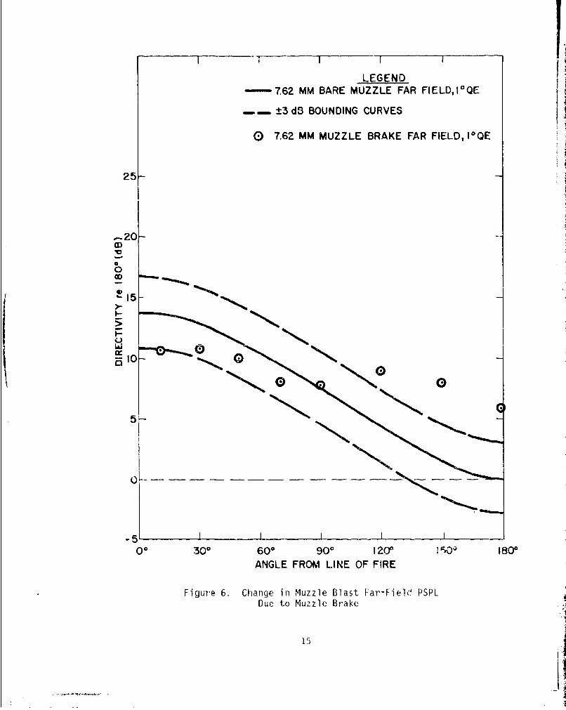
The averaged (for all four measurement distances) effect of the muzzle
brake, from Table 2, is shown in Figure 6 as excursions from the bare muzzle
directivity curve. The significance of the ±3 dB bounding curves (dashed lines)
is that data points that fall between the bounding curves represent an insigifi-
cant noise level change in terms of human perception of noisiness. It can be
seen from Figure 6 that the only significant change in PSPL caused by the muzzle
brake was an increase, in the region behind the gun.** The tested muzzle brake
and its blast field are quite typical of practical muzzle brakes. Hence, it can
be concluded that muzzle brakes are of little use for reducing far-field noise
disturbance.
*This muzzle brake is configuration No. 1 of Reference 24, geometricallyscaled according to gun caliber (bore diameter). 24
*- It is interesting to note that near-field directivity is preserved to fomeextent into the far field, as is the case for bare muzzle directivity asillustrated in Figure 4.
12

)-4 NU
C0 -It a' '-4 C" C0CI
00 00 cc r-~ r- r- cc
-Ym2 -4 L m L
-3 wU CA' O CO -4l <71 Cý ON US4-. J
fit Nc C)r- F-- F r- Q-
E U
a) -4 (1 o C4 - - N 0
ccr- i-) C f l Cl FL-' --I)~
m-. C ' - Oý4 t i 0 t
fnU)m 1-4 a -1 4 - - -q ') ~ ~ ~ -N 1- ' -4 ---1 -- 0
C ' 0'0o' c C~
42)> :-I w' -4 C4 r-4 -1 .1 --1 -1 -1
ce 'U ID Ln C
co -i a i CN ~ CN -1 'I l Ct)c H e - -4 -4 -i .-4 r-4
a))
C 4i-4 Q) P44 -4O -4 -4 Q- C) QC4 Q) -) 1- 04 L4 0'-)
0)0
- *-13

Table 2. Change in Far-Field PSPL Due to Muzzle Brake, 7.62-mm Rifle
Angle A PSPL (dB) @ R (calibers)fromDirectionof Fire All(degrees) 14,000 26,000 80,200 138,000 (mean)
10 -3.1 -3.3 -2.9 -3.0 -3.1
30 -2.4 -0.4 -2.8 -2.5 -2.0
50 -1.5 +0.5 -2.1 -2.5 -1.4
70 -0.6 -2.1 +0.1 -2.5 -1.3
90 +0.2 -0.2 +0.8 -0.7 0.0
120 +3.0 +3.1 +5.8 +6.4 +4.6
150 +5.3 +5.2 +7.8 +8.1 +6.6
180 +6.6 +5.5 +5.5 +6.2 +6.0
CONICAL MUZZLE DEVICES
The effects of conical muzzle devices on near-field gun blast have been re-
ported previously, 16,25,26,27 and some data regarding the effect on recoil27
impulse is also available. In general, the effects are increased peak over-
pressure in front of the gun and in the remainder of the blast field, especially
behind the muzzle, and some decrease in peak overpressure. This amounts to en-
hancement of the bare muzzle directivity. Also,there is some increase in recoil
impulse.
The near-field blast study of SooHoo and Yagla26 presents typical near-field
conical muzzle device results, obtained using the 5"/54 naval gun. Peak over-
pressure data were presented for the bare muzzle -gun and for a conical muzzle
14
I I I I 1LEGEND
- 7.62 MM BARE MUZZLE FAR FIELD,I 0 QE
-.---..±3 dB BOUNDING CURVES
0 7.62 MM MUZZLE BRAKE FAR FIELD, I1OE
25r
q0
15-I
3100
5•
-5 I I I I00 300 60Q 900 I20 1800
ANGLE FROM LINE OF FIRE
Figure 6. Change in Muzzle Blast Far-Fiele PSPLDue to Muzzle Brake
15H
device of 100 half-angle, 4.2 calibers in length, and with an initial inside
diameter of 1.05 calibers. Results are presented in Figure 7* in terms of the
change in PSPL due to the muzzle device. These results are quite typical of a
rather wide range of muzzle devices,27 including cones, cylinders, and parab-
oloids of various sizes. It can be seen that the increase in directivity is sub-
stantial in the near field, but decreases with increasing distance from the
muzzle.
Far-field effects on muzzle blast PSPL were obtained during the present
study for a conical muzzle device of 100 half-angle, with an inside length of
4.0 calibers and an initial inside diameter of 1.1 calibers. This muzzle device
is nearly a scale replica of the device of SooHoo and Yagla26 discussed above.
Data were obtained using the 7.62-mm rifle and test apparatus described earlier.
Results are presented in Tables 3 and 4 and in Figures 7 and 8. Figure 7 shows
the change in far-field PSPL explicitly, and Figure 8 shows the excursion from
the bare muzzle directivity curve.
A preliminary investigation28 of the effect of a conical muzzle device on
far-field muzzle blast also provided some data. The basic philosophy of the
experiment was quite similar to the 7.62-mm rifle tests; differences included the
guns (5"/54), firing interval, instrumentation locations, and that the guns were
fired on a fixed direction of fire, with field measurement locations varied by
moving the instrumentation. The two guns, located about 120 calibers apart, were
fired within about 30 seconds. One of the guns was equipped with a 100 conical26
muzzle device identical to that used by SooHoo and Yagla. The test was fired
during daylight hours, under quite significant atmospheric refraction conditions,
with the result that no data were obtained at some of the desired field points
* The results for angles near 1800 may be strongly influenced by the presence ofthe gun mount.
16

+10LEGEND
E 5V/54, R = 24 CAL
0A 5"/54, R = 48 CAL
A V 5"/54, R = 72 CAL
5 "/54, R = 96 CAL
o 7.62 MM, FAR FIELD
5 5V/54, FAR FIELD+5
OQ00
A003
VV
0*
CC
-10I ' i
00 30 60° 90u 120' 150] 1800)ANGLE FROM LINE OF FIRE
Figure 7. ]hange in PSPL Due to 100 Conical Muzzle Device
27
U, di . .
0n \0~ 0- I-)o~~~~~ cc__ co________________
00 c00 (n 1-i n cli cn- '.n '. n~ (
dNW. N (N 0 . t) - --T \Z
0 0j 0ý Ch 00 ' C C
pqr'0i di.
40 00, 0 r4 C) 0 0 C) In r- C
ck-i
I2 0 co -dC4il . o L
(JLf)CL CD0 0 0) Q
NN .
LL-. 0 Cý 0 '0 00 LM' (N N- IfC> 00 (N -41 -4 ,-i -1 C)
a) .-- r-4 -4-1. -Q CD
C>
LA -4 0 00 :1) '.0 ý
0 0 '.014 -4 r4 C'f 0 4a H - -4 --q -4 -4 C- C
0o 00 L
'-4 -4 N(n N. - 0 f) 'diNr- - -
4N Cf) pq 0(N 0 CD C)~ CD(N "N VN r- ONI CN - .0
C-

Table 4. Change in Far-Field PSPL Due to 10'Conical Muzzle Device, 7.62-mm Rifle Test
Angle A PSPL (dB) @ R (calibers)fromDirectionof Fire All(degrees) 14,000 26,000 80,200 138,000 (mean)
10 +3.2 +2.8 +3.5 +2.7 +3.0
30 +3.4 +3.7 +3.3 +3.3 +3.4
50 +3.4 +4.1 +3.2 +4.1 +3.7
70 +1.8 +1.7 +1.4 +1.5 +1.6
90 +0.2 +0.6 +1.6 +1.0 +0.8
120 -1.7 -1.2 -4.2 -2.6 -2.4
150 -0.8 -0.6 +1.7 +3.1 +0.9
180 +3.4 +5.6 +4.8 +1.7 +3.9
because they were located in a region of greatly reduced sound level. The re-
sultant data are shown in Table 5 and Figures 7 and 8; each datum in Table 5 is
the mean value from up to five test rounds.
The far-field data for the 10* conical muzzle devices exhibited rather large
scatter, so that any conclusions must be somewhat tentative. The presentation
shown in Figure 7 strongly indicates, however, that the near-field directivity
enhancement effect of the conical muzzle device is considerably decreased by the
time the blast wave reaches the distances (R ' 104 - 105 ) at which far-field data
were measured. Figure 8 illustrates that the change in far-field PSPL due to the
19

1 IILEGEND
- 7.62 MM BARE MUZZLE FAR FIELD, r QE
"±3 dB BOUNDING CURVES
0I 7.62 MM CONICAL MUZZLE DEVICE
FAR FIELD, I*QE
13 5"/54 CONICAL MUZZLE DEVICE
25- FAR FIELD, I-QE
:20V
0-
-5-
I I ________00 30* 600 900 120 1500, 10
ANGLE FROM LINE OF FIRE
Figure 8. Charnge in Muzzle Blast Far-Field PSPL Due to 10'Conical Muzzle Device

conical muzzle device 1s generally smaller than 3 dB, and that even these reduc-
tions occur in only a limited portion of the blast field. Such a device i.ay be
of use, however, in some scenarios, e.g., at a firing range that can take advan-
tage of bare muzzle directivity and/or needs only a small increment of further
noise reduction to meet a noise regulation. It should be kept in mind that a
conical muzzle device is generally much lighter in weight than other noise reduc-
ing muzzle devices. Also, the noise reduction occurs in a region where projec-
tile bow shock does not exist, while the noise increase occurs in the bow shock
region and, thus, may be of lesser significance. Finally, the muzzle device
tested in this exploratory development project has not been optimized; it may be
possible to achieve increased directivity enhancement. In summary, it appears
that conical (or possibly other forms, e.g., paraboloid 27) muzzle devices are of
quite limited utility for noise control, but may find application in special
circumstances.
Table 5. Change in Far-Field PSPL Due to 100Conical Muzzle Device, 5"/54 Naval Gun Test
Anglefrom A PSPL (dB) @ R (calibers)Directionof Fire All(degrees) 25,200 76,300 140,000 (mean)
30 +2.3 +2.6 +2.4
70 +0.6 +2.3 +1.4
110 -0.3 -0.3
150 -1.7 -]1.7
21

BLAST REDUCER MUZZLE DEVICES
Many silencers have been built and tested,29,30 including some specifically
intended for use on major-caliber guns.3 1' 3 2 Reductions in PSPL of more than
20 dB have been achieved, generally by means of long cylindrical canisters with
internal baffles. Silencers that yield such dramatic noise level reductions are
generally quite large, often of roughly the same length and weight as the gun
barrel. These are not suitable for use on major-caliber guns except possibly in
special circumstances that would allow the device to be separately supported.
The objective of most previous silencer development programs has been to
achieve great reductions in blast overpressure, to the point of inaudibility in
the far field. Such dramatic reductions would certainly be very desirable for
noise control, but a smaller reduction in far-field noise level could still be
useful. The objective of this portion of the current project was to determine
the feasibility of a blast reducer muzzle device, i.e., a silencer of moderate
effectiveness, that might yield a useful reduction (-10 dB) in noise level and
still be small and lightweight enough to be used on existing major-caliber gun
systems without requiring additional support and without damaging the gun.
Very little information regarding the performance of such devices is avail-
able. An extensive parameter study was planned, using an adjustable blast
reducer muzzle device. The tests were carried out at reduced scale using the
7.62-mm rifle apparatus and procedures described earlier. The adjustable blast
reducer consisted of a cylindrical tube that was mounted on the gun muzzle and
could be fitted with a variety of parts to vary device length, internal volume,
and baffle shape, location, and number. The device is shown mounted on the gun
in Figure 5.
Only two configurations, designated as BR-A and BR-F, and shown schmatically
in Figures 9 and 10, were actually tested. These devices were of a size judged
to be at or beyond the limit of practicality for use on existing large guns. Re-
sults are shown in Tables 6 through 9 and Figure 11. Configuration BR-A, a
cylinder 8 calibers long and 5 calibers in diameter with three curved baffles
22

- ~ 44
4-)
~00)
A94A
CD
or A '
-H U)23

LlI
(4-=
':)C
0)LO
---o
LLA
UI I
C-)
r~:1 4-fj
u-i
('4to
L(0ýzE CD
-lýOf
2: Cco
C(Li
lo:
24

or co Lt0r 0 r
0
cu,-' ,4 w N Z 1ý 1
fcl~f a 7\ c
4-)~
:-4
ý4 10 0 O
0 O\ co
cu c
LL- 0 00 -4
U- v-I
0 .)JN
0 v-o v- 0
(n
C4 -4 C0 (
I-l 1-4 ,-1 v--I ý
00)(
4-4 0v-I (NJ cc c'.
$-4N 25
Table 7. Change in Far-Field PSPL Due to Blast Reducer BR-A
Anglefrom A PSPL (dB) @ R (calibers)Directionof Fire All(degrees) 14,000 Z6,000 80,200 138,000 (mean)
30 -5.1 -4.7 -3.5 -1.3 -3.6
90 -4.1 -3.0 -1.7 -5.4 -3.6
150 -0.7 -2.4 -4.0 -9.1 -4.0
spaced at 2 caliber intervals, yielded a PSPL reduction of -4 dB. Configuration
BR-F, a single curved baffle design with an expansion chamber, yielded -5 dB
reduction in PSPL. Reductions of these magnitudes probably do not justify use of
such large, heavy muzzle devices.
WATER SPRAY
An interesting concept for gun blast noise reduction is to introduce some
substance into the muzzle region that could interact with and remove energy from
the blast wave. It would be desirable for this substance to be cheap, easily
handled, and of minimal environmental impact. A substance that comes immediately
to mind is water. The total energy released by the propellant of a 5"/54 naval
gun is on the order of 5 x 106 ft-lb (1.6 x 10⁶ cal), which is equivalent to the
heat of vaporization of a few liters of water. Actually, less than half of the
propellant energy goes into the blast wave. 3 3 A difficulty is that the time
available for the energy interaction to occur is very short.
26

N% U' Vl)
0% m % 00
CA
-Hr) ) r- C
s-o 0 0% O
ImI
00
'-4
V) -1 - r-4
C0 C4 0%CC) '-4)
U)NU) U
-D4-
-j ad cu
U- C.)
00 04 $0cW -A i-I V- ,
Li- ~ i]27

Table 9. Change in Far-Field PSPL Due to Blast Reducer BR-F
Anglefrom A PSPL (dB) @ R (calibers)Directionof Fire All(degrees) 14,000 26,000 80,200 138,000 (mean)
30 -1.3 -1.1 -0.5 -1.9 -1.2
90 -3.5 -3.3 -7.2 -6.7 -5.2
150 -4.4 -4.2 -8.6 -5.5 -5.7
A preliminary feasibility investigation was conducted to determine if sig-
nificant noise reductions could be readily achieved by means of water spray. Two
series of exploratory experiments were performed, using the 7.62-mm rifle and a
40-mm naval gun, respectively. Water spray was provided for both tests by fire
department equipment, specifically a "Grant Gun" equipped with a "Fog Hog"
nozzle, with water supplied from a hydrant by means of a pumper truck and 3-inch
diameter fire hose; flow rates were on the order of hundreds of gallons per
minute. The nozzle was adjusted to give the finest spray (smallest droplet size)
attainable; no other control or measurement of droplet size was attempted. The
water spray obtained appeared to be a fine, dense mist, i.e., the droplet size
appeared to be quite small by ordinary standards, although they were very prob-
ably much larger than micron-size. The spray was directed at about 901 to the
line of fire, from a point to one side of the muzzle that resulted in the muzzle
region being engulfed by fine, dense mist, as shown in Figure 12. The mist was
so fine as to be greatly affected by even moderate wind.
The 7.62-mm rifle experiment used the rifles discussed earlier, shown in
Figures 5 and 12. The gun muzzles were covered by a small piece of tape to pre-
vent water entry. The firing procedure was to first establish suitable water
28
I 1 1
LEGEND
--- 762 MM BARE MUZZLE FAR FIELD,I-, QE
-=- 3 dB BOUNDING CURVES
0 BR-A
A BR-F
25
C13
*A
10-
5-
BLAST REDUCERSA
-5 I
0° 301, 600 90g 1200 1500 180IANGLE FROM LINE OF FIRE
Figure 11. Change in Muzzle Blast Far-Field PSPLDue to Blast Reducer Muzzle Devices
29

ttŽ��rs A{L�-
4 � 4 -.
it 'nA$' svga #. t \ Ths�k Ii'*.- t- £
(V*. "r w4.
� �
t� *�a:
7%
4$,
(V
acn
t J�f , tt�"'fr 'a'1T !MI�� -
'NJ- r4
is � >.� *� kTM
I '�'t&4�t¶'� jWŽ.� L
-t
4%a� �A4t' I 4
� �' A; "7,
'a� :���j' :4., 4'
30

spray, fire the lower gun, turn off the water spray, and finally fire the upper
(baseline) gun; elapsed time between firing of the two guns was about 10 to 12
seconds. Instrumentation consisted of six Gen Rad Model 1982 sound level meters
and the automated data recording system described earlier. Instrumentation field
locations were at 45, 90, and 1350 to either side of the line of fire, at a
radial distance of 4,000 calibers from the gun muzzle. Projectile bow shock was
eliminated from the blast field by means of a bullet trap.
Results of the 7.62-mm water spray experiment are shown in Table 10. The
average reduction in PSPL due to the water spray was only 1.6 dB, a reduction
large enough to be interesting but not large enough to be useful.
Another water spray experiment was performed using a fairly large gun, the
40-mm naval gun. Far-field instrumentation and data acquisition apparatus was
similar to that for the 7.62-mm rifle, except that only four Gen Rad 1982 sound
level meters were used, located 90 and 1350 to either side of the line of fire
at a radial distance from the muzzle of 1,143 calibers. Near-field overpressure
was also measured by means of two Ostronics Model PB-200 pencil-type blast
gages pointed at the muzzle and located at 450 right, 66 calibers and 1050 right,
55 calibers; data was recorded onto a Honeywell Model 5600 tape recorder.
The gun was a standard 40-mm naval gun with the conical "flash hider" muzzle
device removed and was fired at an elevation angle of approximately 00. The
muzzle was covered with 4-mil plastic film to prevent water entry. Ammunition
consisted of standard service propelling charges and Mk 2 inert projectiles. No
attempt was made to stop the projectile to eliminate projectile bow shock from
the blast field; no measurements were made in the bow shock region of the far
field, and the bow shock PSPL is much smaller than the muzzle blast PSPL in the
near field. The water spray in all cases was directed at •900 to the line of
fire, with the spray apparatus located at various positions as required, for
various spray nozzle adjustments, such that the gun muzzle was engulfed in the
fine mist portion of the spray pattern. Flow rate throughout the test was
approximately 600 gallons/minute. Because the gun had to be reloaded before each
shot, elapsed time between water spray and bare muzzle shots varied from 40 to
120 seconds.
31

aj i-i
-4 -4~4- r
4+-4 Q-H hý C
d) 0l 1-4 .-4 N- r-4 (7-400 C
aLi-i E 4J
0 .4-1 N . o- . r-l r4 ., 0 Ltn cat
(a4 -1 I'D '.D 0 '.n 0 O P I ' rý -4 00 a' -S.- C' N I C14 N I C- Nq I I 4-i
v.'. Lfl -i r-4 1-4 -1 -
ý4-
4-) 4-1i
CD \00ým L 7
7-1 co-* w ~ 0 N N 0 0' -4 C'CA CIA I N ' N N I 1 I 4E
t4L' - - - ,-q -
--I c 4
~~0LO 00 V. ID '-' '0 rA 0o I-- Pn cn0
I! 4 m -ý C'',l 70) 4 Ne N m4 I m- N1 P. C14
(D -4 - 4-.4 1- -1 0. '
sI C ) 0 00 C-1 oa) 00J a)4 (ON 0) a) af) W
CCN. Lr r-4 -1 -4 1-4 1-4 1.4 r -
4.)
N4 N z ý A4.
h1ý 0ýS37" ý

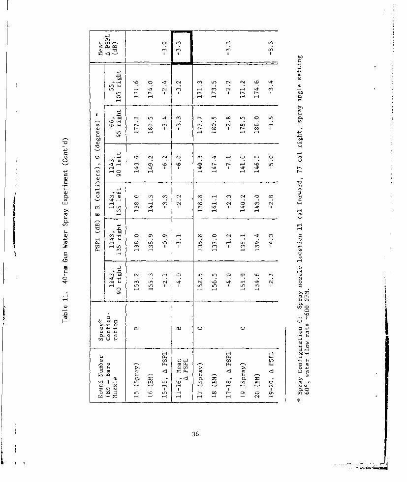
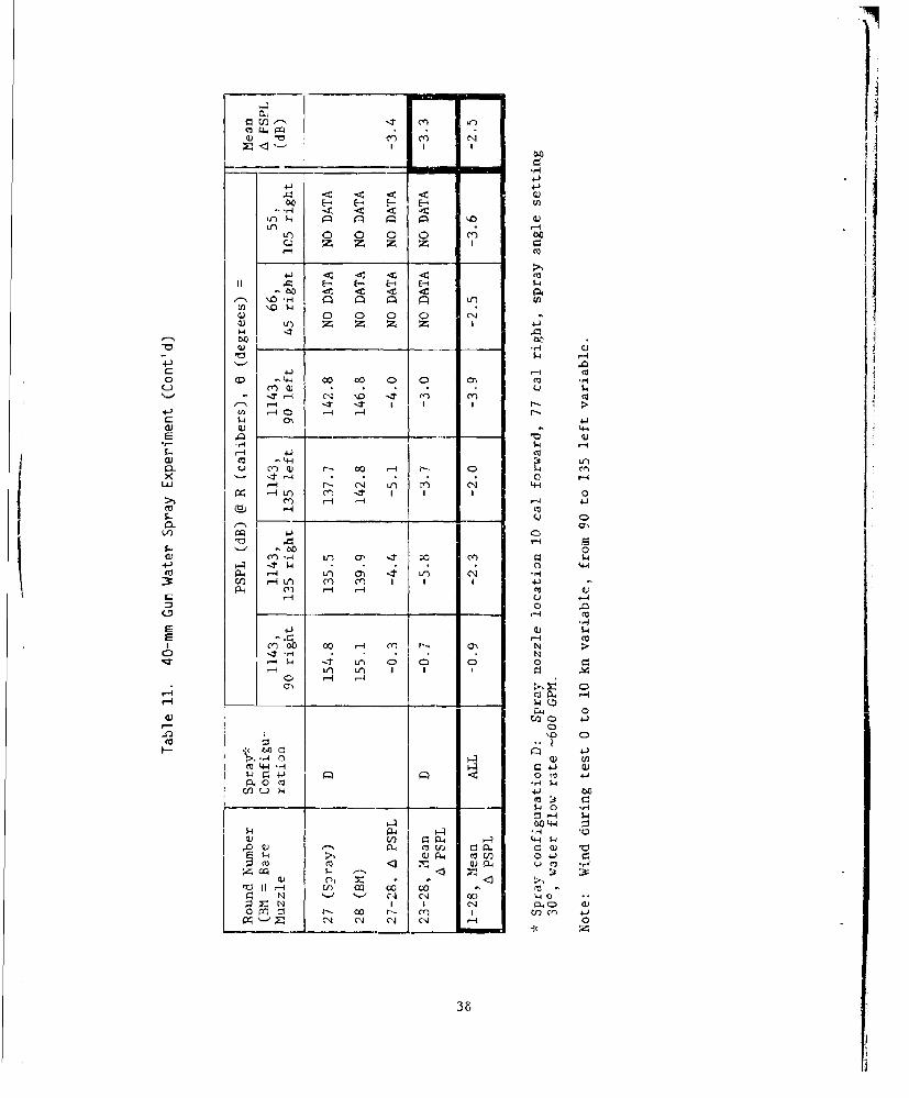
The results of the experiment are shown in Table 11. The overall average,
for near-field and far-field data, of the change in PSPL due to the water spray
was -2.5 dB. The far-field data exhibited considerable scatter, but on the
average the PSPL values for near field and far field agreed fairly well. Spray
configuration seemed to have little effect on change in PSPL as long as the gun
muzzle was engulfed in the fine mist region of the spray (spray configurations
B, C, and D); for these cases the PSPL reduction was about 3 dB, compared to
about 1.5 dB for spray configuration A (muzzle engulfed in the high-velocity jet
region of the spray pattern).
The PSPL reduction of about 3 dB that was obtained is of little utility for
noise control except possibly under special circumstances.* The reduction is,
however, large enough to be interesting, and perhaps merits further investigation
(no further investigation was undertaken during the current project).
It is difficult to speculate on what changes should be made to the water
spray characteristics, since the phenomenological mechanism that produced the
PSPL reduction is not known. It seems plausible that a dense concentration of
much smaller droplets might be required, which would make the mist even more
susceptible to disruption by wind.
FOAM
Recent experiments 3 4 ' 3 5 have shown that foam can yield large reductions in
airblast PSPL from explosive charge detonations. In these experiments, the ex-
plosive charge was engulfed in aqueous foam such as is used in firefighting. A
preliminary investigation into the utility of foam for reducing gun muzzle blast
noise was carried out as part of the present project.
The foam that was used in this initial investigation was shaving cream, con-
tained in a small (diameter ý2O calibers) plastic bag taped to the muzzle of the
* See "CONICAL MUZZLE DEVICE" section for further discussion.
33

C-- -u) C) C.) n)
-I- < <- 4-
10.
(0E-~ E--e
co 0V 00 <c (y) C%4Cl
(n r-4 Z4 Z- L-n - 4 - -
-4
a) -'t -1 V- -Zr m- r- cc CD1 F- cc C'
LA -4 C:5) r- r-4 r- -40C) r- )~.
cu - - 4 -
X_ _ _ _ _ _ _ _ _ - -LLI 4-1
m -4C-
cc i U-. co (1) -1 -,: +4 -i1 Cf' +c a' -.-- . 0 -4 r-- 4 1H- .- 4, -
rf) -- 44 1- -
CC' .,4 .- .-4 -4 C"
_1T,- -4 CC' 0> C-) 0. C) N- - ) m' '0) CC'
_ _ _ _ _ _ _ _ _ 0
4I (U- C. 9w.0 0
04 (Q0 M )V) P PQ) .4)
C) CQ I
,-4 CA -4 Cen CO' i) \,D LC) r- 00 N-
3/4

600
-~ 01
w 0 cc ) ~ -It Cr r-.7 -.7 r-4 I.7 (A
'-4 C
C14 C) N 00 00 '.0Iý 00 NN 1.40 (
caý CDs ---- \- -O a-\ Il aIz r- aY\40 -4 r- I
- ~ 00 GO70 -4
o: -4 4-4'
r- -4 -4 -- 4 r4'- -4-
4-1 (/1 C) , ný
CD- u Q) O1) cO 0~.- C) C) (N- 00j 0l (n aN 0'-7
0- (-1 -4
'0 D4
S-. a-r-- CD C-) 00 0-
CDau4 (n () I I l Y 1 -'4DtE - , i ri-4 -4-4 -- 1
low v-4) m- 4C
C: -4 Q
S IC,. LO N-- 1 0 1 I
-4I 7 -7 I + V. L) 1 -.2 LO) I0
-4 -1 CI-4v- -
Ul) Co- C)
F;> -r- 00
>- 4 H 0 m01
0 -
~~O CO ~44
PQ W) 44 45
o1 :5. Cl) C: -4 ()) V) 0LI
01A V-4 r- r-4 -1
VII-4 U) --<~~350 C N ) C~-7C
-~ 4J
-,4 zf C t 04 C') Lr) CA c' -
I) 1-4 It C-.) Cl) m- N' -4 - ' 'Le r r- I t I-. I -. -C) - -q 1-4 '-4
Le)-. n 4 C r-- Lfn 00 in) 0 LIl
U) 0~ t_: 0, rý ('1 2- 0 C') Co 0 -4r- 00 1 1 r-- 00 1 r- 00 1
cu 11) r-1 .- 1 r-4 l-4 -4 r-4 4.
<D 0 4-4 Cl N CD m It -~ 4 CD C) C 03C-.) clJ -* u"Cl a-i m. CC 0L r0 1 - r-- -4 '-
-ý 4 'IT - I 4 - -It It -1 -- I r-..4-) U I C) 1-4 ,-1 1-4 r-4 .- 1 1-2--
r- "+41
CL u m.) Q co Clq co -4 ce) Clj 0 co.
ClJ -4 0 -4 Hl Cý 0 4 N Cý N4-
>1/ CCo- -
a)) l,-4 0 UN a) -14 00 C. C4 r-4 -. C')
in l li) cn ml I I C ') m ~ C I o*r
'U -4
4-J
CD ItA
-ri4 0Co Lýl .,A C-) +.i-
$, - ; ~4-J
U ) Q< ý- 4J
0Co it) 'vC Ut) V) 4-- CC ý- 0 0P, m~ A, P.4 w4 - '~
~~. --4--$

00 E-' E-A F- E- E" 0- < 17 U') Ný a a, g < -ý
In . (D) C) C C) Cr-4
(D r-' 00 1 1 '0 0 0 C0 C)0
0 q Co 0 " 4n C4 "0 <~4(L) In~ :z 0 z N C
ý4-
<D 0 ý It -4 U) -1 " lz ,-1 IT Cr) '
lzrr-.4 r-4 Co r- r_: '-- 0 C") Co Vi),~-' -4A -IT I 4 - '4 + -4 It I t'-U) I r-40 r 4-4-
H-1
Q.I u - C) a) '-4 'T (Y' (A cr4 I'D C4 %04-LL ,-At C') C") 4 ý 04 (Ci %4 0 -. t 4-
fx 1-4 In c m I I M t I3Y :M r-
cu(n -4 -4" J.) ON (' all C14 (Ci co if) r' C4 '4 ONCr4 - f 0 - - 0'-
m a, r 44
-4 -4) -4 r-4* 0Ci
:1:U) Lq/I) M" mC +- I ce) -tr I CC) 4z 4
m- -4 -1 0q - -q 14I
m- m f if'4 I4 Y -IV t) (11 f)C)) +T -,q
I n If I I) L-)
-1 ) -41 ~0m
(v 0ý4' 0
d)V) a V)) vi 4I-1a4 co ) 04 P4 q 4
V) U) N .4 w) CI 4. C
N 04-0N r:4 C
'0II- -4 Al N In)~ 4. U 0
j 27
9.1 < <CI E-~ E F H"1-4 < ~
if.) IIfr) 0 0 )
", o -H 92 1 I ILG) - 0 -40
41 Q
(.2 cl)q r It- I. ~ - - 0 -1-4** 0 r-4-
r-~ 4 C 0-0 4 Cf N
-AI Lu' cc, Icc
(.1n-1 - 4-1
m '-4S.-O Co , c '- 0
4- P r in 440 0
PL, in) I- G
(j -4
41.
r-4 I4 4 .- 4J Q .
-4 ::
-- CZ 41.40 w *,-)P4 0 M -4 W -
4-4 -1 -4
z)0 -4 Vý43 :j:
a) II -4 £22 4-1 SC CCI N '-', r- Ow CN w) 1w
S- 4 VN 0 4) 0)C13t co h-Ac u t cl-i .~
a N CA Nl -o 04
38

7.62-mm rifle, with the gun muzzle located approximately at the center of the
foam mass. A small piece of tape over the muzzle was used, as a safety precau-
tion, to prevent entry of foam into the gun barrel. Apparatus and procedures
were similar to those discussed earlier; data was obtained only at 90* from the
line of fire. Resultant data is shown in Table 12.
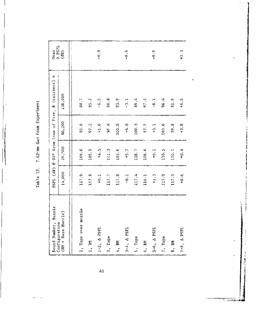
The foam produced about a 10-dB decrease in muzzle blast PSPL. The data
clearly shows that the effect was not due to the tape over the muzzle or the
presence of the plastic bag. These results were extremely encouraging, espe-
cially in light of the small reductions obtained by other techniques, and moti-
vated an expanded investigation. Results of that investigation are reported36,37
under separate cover.
SUMMARY OF CONCLUSIONS
1. Muzzle brakes yield a small decrease in noise level in front of the
gun (in the projectile bow shock region) and a fairly significant increase behind
the gun and, hence, are not expected to be useful for gun blast noise reduction/
redistribution.
2. Blast focusing muzzle devices yield small increases in noise level in
front of the gun and small decreases behind. Such devices, being relatively
lightweight, may be of limited use for noise control under special circumstances.
3. Blast reducing muzzle devices (silencers) that yield large noise level
reductions are very heavy; those that are light enough to be used on existing
large guns yield insignificant noise level reductions.
4. A preliminary (and somewhat cursory) investigation of the feasibility of
using water spray to reduce gun blast noise levels yielded only small (-3 dB)
reductions in PSPL. The water mist was quite susceptible to disruption by wind.
5. A limited preliminary investigation of the use of foam to reduce gun
blast noise was quite encouraging; a 10-dB drop in muzzle blast PSPL was obtained37on the first try. Further investigation is reported under separate cover.
39
1) C) C) 0 IN
'-4 Cco C
C~ ~~ <Y Mf r- 00 -4ý1 io,4 -± a t
0) co4 a)1-% Qý0 F0.
X044 '. C14 I'D oo c0 0 cn C1 4 . 00 4:11
m 4~ %L C .1 Q -. y l
LL- r. 'h. 0 40 h ~C~
E -4 c- -4
Il 0~ V0C) CC) '.. e- CD0 +f C4 '0 +- C-- '0 +- r, ~-4 +
'. '0 00+ Cr-+C:) ~~~~~- 00r r t -4 M4, n \
04 0
I') 4 ) N
00 44 A4 AAP6
C/) 0.) 0) 0)
10.4(o co mV XV ct
CJ'0 4- 0 po0 0 q- I -
Ur4i cA r-4 ~ m - M' ,if) 10 un Go. 0
404

(13, P., 0 ;
Vl C e \0 0V r- CI0 00 C
0 0C ) 0 mI-q U P
CY /q
r-~ 0n N~ m. cc I- CN oLO
a-) V; _ _ ________ cn
0)
S-4 0 CDi ~ 4 ' '0. 0D 09 +ý 4- 0 0 +
Lý -0- -4 C-3 C4 I aC1
0I + ('I -4( + 0
Il-i
ýo n r % 00 C% ý
N- -1+ -1-'+-
P4 PH -
N S S
N4 (04
Z1 00..~O 4 0 4 c0) +0 a4 +- CO O
,04 4- 0, QL4 410
0 Ij M a m 4-4 m' w 4
0000 0' '-4 0' ,-4 -4 ,- . - - - -IZ CC.)ol I
41

+4 +
a1 'V -4ND 1D
0- 00 r4 -o N 1 00 CU .C4 cn
4J. (U C)..
0 '.-' e. e14 Of- It4 R 0'i~ fCL 0 + + 0 ' ON -4 0a% I
C 44 CN r i C )L
Z) (7% -1 - 0 -4 C)' N r C-i C>. ICD ' 0 4D - + C, 0. '-1 0' C) I (
(0 41.4 r-4 r-q I U- t
E ,- _ __ __ _ __ _
-44 0 r-4 .- .- -q
P-44
04-1
N PN 0) 4
mZ N 4J"uQ
0 w 0-. PL4PL 0(L- ) Q(A Cd) u -
-. +P.. m. r--.w44- (U 0C13 ) <I r. m4 < % < (
z m P4 4J~ P:4 (00 (t . - u 0 0
' 11 F- C ýo '0 41>, co- .0 [P2. 3; cý sr--1 -4444ý J 4 (N (4
rZ IC.ýP '0I000 PQ1'. '.0 .r4 'W Irg -- C4 a- 0' 0 01
-4-I r-4 _-'1 r-4 - 4 ~ <N
42

0.0In I
4-)
o 00 N -4 -4
41 m
1-4
0- (' ) cn - ~ 'a): 0 0 1-
0 4) 0 04 as4 -4 -
fLL 02
c* ~ -4 .9
P4
.00
CU 0
-4 c
N F4N a) Aq
N4z < ~0
o0 Xi'-Q) H u)
141~ 4)
wV41 pq C N Q)~4-1 N NUI (
UO - CN C
43
REFERENCES
1. Pater, L., Oun Blast Far Field Peak Overpressure Contours, Naval SurfaceWeapons Center Technical Report TR 79-442, Dahlgren, VA, March 1981.
2. Perkins, B., P. Lorrain, and W. Townsend, Forecasting the Focus of Air BlastDue to Meteorological Conditions in the Lower Atmosphere, Ballistic Re-search Laboratory Report No. 1118, Aberdeen, MD, October 1960.
3. Perkins, B. and W. Jackson, Handbook for Prediction of Air Blast Focusing,Ballistic Research Laboratory Report No. 1240, Aberdeen, MD, February 1964.
4. Gholson, N., An Analysis of Sound Ray Focusing, Naval Surface Weapons CenterTechnical Report TR-2834, Dahlgren, VA, January 1973.
5. Bankston, T., Sound Focusing on a Non-Reflecting Flat Earth in a StratifiedAtnvsphere, Pacific Missile Range Technical Memorandum PMR-TM-62-8, Pt.Mugu, CA, May 1962.
6. Ugincius, P. and B. Zondek, Acoustic Rays in an Arbitrary MAving Inhomogen-eous Medium, Naval Surface Weapons Center Technical Report TR 2446,Dahlgren, VA, August 1970.
7. Pater, L., Noise Abatement Program for Explosive Operations at NSWC/DL,Seventeenth DDESB Explosives Safety Seminar, September 1976.
8. Reed, J., Guidelines for Fnvironmental Impact Statements on Noise (Air-blast), Sandia Laboratories SAND 76-5661, Seventeenth DDESB ExplosivesSafety Seminar, September 1976.
9. Kahler, J., FOCUS: A Computerized Aid for Making Sound Propagation Fore-casts, Holloman Air Force Base, NM, ADTC-TR-79-8, January 1979.
10. Schomer, P., Predicting Comnunity Response to Blast Noise , ConstructionEngineering Research Laboratory Technical Report E-17, Champaign, IL,December 1973.
11. Schomer, P., L. Little and A. Hunt, Acoustic Directivity Patterns for ArmyWeapons, Construction Engineering Research Laboratory Interim Report N-60,Champaign, IL, January 1979.
12. 6ttidelines for Preparing &ivironmental Impact Statements on Noise, Report ofWorking Group 69 on Evaluation of Environmental Impact of Noise, Committeeon Hearing, Bioacoustics, and Biomechanics, National Research Council,National Academy of Sciences, Washington, DC, 1977.
44

13. Schomer, P., Humcm Response to House Vibrations Caused by Sonic Booms or AirBlasts, J. Acoust. Soc. Am., Vol. 64 No. 1, July 1978, pp. 328-330.
14. Schomer, P., Evaluation of C-Weighted L for Assessment of Impulse Noise,J. Acoust. Soc. Am., Vol. 62 No. 2, Augu-l 1977, pp. 396-399.
15. Environmental Protection: Planning in the Noise &hvironment, Departmentsof the Air Force, the Army, and the Navy, AFM 19-10, TM 5-803-2, NAVFACP-970, 15 June 1978.
16. Walther, M., G6n Blast from Naval Gtns, Naval Surface Weapons Center Tech-nical Report TR-2733, Dahlgren, VA, August 1972.
17. Soo Hoo, G. and G. Moore, Scaling of Naval Gin Blast Peak Overpressures,Naval Surface Weapons Center Technical Note TN-T-7/72, Dahlgren, VA,August 1972.
18. Westine, P., Modeling the Blast Field Around Naval G•ns and ConceptualDesign of a Model Gn Blast Facility, Southwest Research Institute Techni-cal Report 02-2643-01, San Antonio, TX, September 1970.
19. Moore, G., F. Maillie, and G. Soo Hoo, Calculation of 5"/54 Muzzle Blast andPost Ejection &vironment on Projectile, Naval Surface Weapons Center Tech-nical Report TR-3000, Dahlgren, VA, January 1974.
20. Soo Hoo, G., 64n Blast Experiments with an 8"/51 (n, Naval Surface WeaponsCenter Technical Note TN-T-1/75, Dahlgren, VA, February 1975.
21. Moore, G., G. Miller, and D. Pollet, QUn and Missile Blast on Ship's Struc-ture, Naval Surface Weapons Center Technical Report TR-3588, Dahlgren, VA,November 1977.
22. Schmidt, E. and D. Shear, Optical Measurements of M&zzle Blast, AIAA Jour-nal, Vol. 13, No. 8, August 1975, pp. 1086-1091.
23. Pater, L., Scaling of MAzzle Brake Performance and Blast Field, Naval Sur-face Weapons Center Technical Report TR-3049, Dahlgren, VA, October 1974.
24. Pater, L., Muzzle Brake Parameter Study, Naval Surface Weapons Center Tech-nical Report TR-3531, Dahlgren, VA, October 1976.
25. Marino, C., Polar Blast Fields About 105 mm Cannon; 105 mm Cannon withDifuser; and 40 mm Cannon as Applied to the C-130 Glinship, Naval SurfaceWeapons Center Technical Note TN/G-36/71, Dahlgren, VA, June 1971.
26. Soo Hoo, G. and J. Yagla, Use of a Conical MuzzZe Device to Control (.nBlast, Naval Surface Weapons Center Technical Report TR-2793, Dahlgren, VA,August 1972.
45

27. Pater, L., Muzzle Devices for Reshaping Gun Blast Fields: An ExperimentalParameter Study, Naval Surface Weapons Center Technical Report TR 79-160,Dahlgren, VA, September 1979.
28. Pater, L., Gun Blast Far Field Asymmetry, Interim Letter Report, Naval Sur-face Weapons Center, Dahlgren, VA, October 1977.
29. Skochko, L. and H. Greveris, Silencers, Frandford Arsenal Report R-1896,Philadelphia, PA, August 1968.
30. Garenther, G. and J. Moreland, Acoustical Considerations for a Silent WeaponSystem: A Feasibility Study, Human Engineering Laboratories Technical Memo-randum 10-66, Aberdeen Proving Ground, MD, October 1966 (declassified 31December 1972).
31. Sneck, H., Cannon Muzzle Blast Noise Suppression Facility, WatervlietArsenal Technical Report WVT-TR-75043, Watervliet, NY, July 1975.
32. Watson, J. and R. Lundquist, High Speed Projeotile Impact for Mining andTunneling - Project REAM, Physics International Co. Final Report, ContractH0232052, Bureau of Mines, May 1974.
33. Interior Ballistics of Guns, Army Materiel Command Pamphlet AMCP 706-150,February 1964.
34. Clark, A., et al., The Reduction of Noise Levels from Explosive Test Facil-ities Using Aqueous Foam, Royal Armament Research and Development Establish-ment, Ft. Halstead, Sevenoaks, Kent, U.K., 1976.
35. Dadley, D., E. Robinson, and V. Pickett, The Use of Foam to Muffle Blastsfrom Explosions, paper presented at IEP-ABCA-5 Conference at Indian Head,MD, June 1976.
36. Pater, L., and J. W. Shea, Use of Foam to Reduce 'Gun Blast Noise Levels,Naval Surface Weapons Center Technical Report TR 81-94, Dahlgren, VA, March1981.
37. Shea, J. W., and G. S. Miller, Reduction of 5"/54 GUn Blast Overpressure byMeans of an Aqueous Foam-Filled Muzzle Device, Naval Surface Weapons CenterTechnical Report TR 81-322, August 1981.
46

DISTRIBUTION
DirectorDefense Advanced Research Projects Agency1400 Wilson BoulevardArlington, VA 22209
Department of Defense Explosive Safety BoardHoffman Building2461 Eisenhower AvenueAlexandria, VA 22331ATTN: T. Zaker
CommanderNaval Amphibious School/Little CreekNorfolk, VA 23521
CommandantHeadquarters, U.S. Marine CorpsWashington, DC 20380ATTN: MCOTT (2)
MCOTO
DirectorDevelopment CenterMarine Corps Development and Education CommandQuantico, VA 22134
U.S. Army Engineer Research and Development LaboratoriesFt. Belvoir, VA 22060
Commanding GeneralWhite Sands Missile RangeWhite Sands, NM 88002
Southwest Research InstituteSan Antonio, TX 78291ATTN: P. S. Westine
CommanderNaval Weapons CenterChina Lake, CA 93555ATrN: Code 6223 (PuIlen) (3)
Code 0632 (Finder)Code 6224 (Young)T. Dodson

DISTRIBUTION (Cont'd)
CommanderNaval Sea Systems CommandATTN: 62Y11 (W. Greenlees) (4)
62YIB (T. Lee)62R (Edwards)04H (Daugherty)
CommanderNaval Facilities Engineering Command200 Stovall StreetAlexandria, VA 22332ATTN: 2013C (D. Kurtz) (3)
0451D (Buynak)032B (S. Hurley)
CommanderNaval Air StationNorth Island, CA 92135ATTN: 661 (R. Glass)
Chief of Naval OperationsThe PentagonWashington, DC 20350ATTN: OP04E (CDR Greenwald) (6)
0P45 (C. Zillig)0P0980P0990P991B (Malehorn)0P64
CommanderNaval Environmental Support OfficeNaval Construction Bn. CenterPort Hueneme, CA 93043ATTN: 2522 (D. Owen)
CommanderAtlantic Fleet Weapons Training FacilityFPO, Miami, FL 34051

DISTRIBUTION (Cont'd)
CommanderBallistic Research LaboratoryAberdeen Proving Ground, MD 21005ATTN: Dr. Ed Schmidt
CommanderMaterial Test DirectorateAberdeen Proving Ground, MD 21005ATTN: R. Ainsley
Darby-Ebisu and Associates, Inc.354 Uluniu StreetKailua, HI 96734
CommanderAMSSAAberdeen Proving Ground, MD 21005ATTN: W. Hughes
CommanderU.S. Army Environmental Hygiene AgencyAberdeen Proving Ground, MD 21005ATTN: Bioacoustic Div. (G. Luz)
CommanderU.S. Army Human Engineering Lab.Aberdeen Proving Ground, MD 21005ATTN: Garinther
Director6570 AMRL/BBEWright-Patterson AFB, OH 45433ATTN: Dr. H. Von Gierke
Bolt Baranek and Newman, Inc.50 Moulton StreetCambridge, MA 02138ATTN: K. Eldred
Wave Propagation LaboratoryBoulder, CO 80302ATTN: Dr. Freeman Hall
Office of Naval Research800 No. Quincy StreetArlington, VA 22217ATTN: 441 (Libber)

DISTRIBUTION (Cont'd)
CommanderNavy Personnel R&D CenterSan Diego, CA 92132ATTN: 311 (Newman)
CommanderNaval Material Command2211 Jefferson Davis HighwayArlington, VA 20360ATTN: 036 (J. Sivy) (2)
0324 (CDR Tadlock)
CommanderVandenburg AFB, CA 93437ATTN: SAMTEC/SE (C. Gardner) (2)
SAMTEC/WE (Maj. Burnett)
Commander6585 TESTG/WEHolloman AFB, NM 88330
CommanderArmy Combat Surveillance and Target Acquisition LaboratoryFt. Monmouth, NJ 07703ATTN: DELCS-S (J. Silverstein)
CommanderNaval Surface ForcesU.S. Atlantic FleetNorfolk, VA 23511ATTN: N625 (Capt. Lindsey)
CommanderU.S. Army Engineer CenterATZA - PTSTFt. Belvoir, VA 22060
Commander in ChiefU.S. Atlantic FleetNorfolk, VA 23511ATTN: ITRT2 (CDR Eckhoff)
Navy Environmental Health CenterCincinnati, OH 45220ATTN: A. Johnson

DISTRIBUTION (Cont'd)
Naval Ocean Systems CenterSan Diego, CA 9Zi32ATTN: Acoustics, Behavior, and Communication
Group (R. S. Gales)401 (R. Young)
Naval Pacific Missile Test CenterPoint Mugu, CA 93041ATTN: D. Robertson
Bureau of MinesNoise Research Laboratory4800 Forbes AvenuePittsburgh, PA 15213ATTN: A. Burkes
Bureau of MinesRolla Metallurgy Research CenterP.O. Box 280Rolla, MO 65401ATTN: A. Visnapoo
Commander Third FleetPearl Harbor, HI 96860ATTN: N33
Bolt Baranek and Newman, Inc.21120 Vanowen StreetP.O. Box 633Canoga Park, CA 91305ATTN: Dr. B. Galloway
Sandia CorporationP.O. Box 5800Albuquerque, NM 87115ATTN: Jack Reed
Commanding OfficerU.S. Army Fort A.P. HillBowling Green, VA 22427

DISTRIBUTION (Cont'd)
Office of Noise Abatement and ControlEnvironmental Protection AgencyWashington, DC 20460
Air Force Aerospace Medical Research LaboratoryWright-Patterson Air Force BaseFairborn, OH 45433ATTN: Biodynamic Branch (J. Cole)
Army Ballistics Research LaboratoryAberdeen Proving GroundAberdeen, MD 21005ATTN: A. LaGrange
Army Environmental Hygiene AgencyBioacoustics DivisionUSAEHA, Building E-2100Aberdeen Proving GroundAberdeen, MD 21005ATTN: D. Ohlin
Army Materials Systems AnalysisAberdeen Proving GroundAberdeen, MD 21005ATTN: B. Cummings
Army Mobility Equipment Research and Development CenterFt. Belvoir, VA 22060ATTN: J. Hoeschen
Army Tank - Automotive CommandWarren, MI 48090ATTN: D. Reese
Naval Aircraft Environmental Support OfficeNAVAIRE WORKFAC North IslandSan Diego, CA 92135ATTN: R. Glass
I

DISTRIBUTION (Cont'd)
Naval Air Development CenterWarminster, PA 18974ATTN: Air Vehicle Technology Department (W.C. Hallow) (2)
Crew Systems Department (D. DiSimone)
Wyle Laboratories128 Maryland StreetEl Segundo, CA 90245ATTN: L. Sutherland
DirectorU.S. Army Construction Engineering Research LaboratoryP.O. Box 4005Champaign, IL 61820ATTN: Dr. P. Schomer
Defense Nuclear AgencyHybla Valley Federal Building6801 Telegraph RoadAlexandria, VA 20305ATTN: J. Moulton
CommanderU.S. Army Armament Research and
Development CommandDover, NJ 07801ATTN: M. Salsbury
Defense Technical Information CenterCameron Station (12)Alexandria, VA 22314
Library of CongressWashington, DC 20540ATTN: Gift and Exchange Division (4)
GIDEP Operations OfficeCorono, CA 91720
Local:CCD-03 (Pifer)DE41G14 (Jones)

DISTRIBUTION (Cont' d)
Local: (Cont'd)G31K50 - EG&G (Library)N01N43 (20)R14 (Young)R15 (Swisdak)R15 (Berry)R15 (Proctor)R15 (Lorenz)X210 (6)