no. 44 april 2015 steel construction - jisf · 13 dismantling methods for steel bridges 14...
TRANSCRIPT

STEEL CONSTRUCTION
Issue No. 44 highlights demolition technologies for high-rise buildings and bridges. The basic aim of demolition or
dismantling is to renew, rebuild or reuse old structures.
Commendations for Outstanding Achievements in 2014
Special Feature: Demolition of High-rise Buildings and Bridges
Special Issue: Japanese Society of Steel Construction
Effects of Weld Toe Shape on Brittle Fracture Occurrences; Hydrogen Uptake Affecting Delayed Fracture of High-strength Bolts
6
Demolition of Steel Structures7 Closed Demolition Method8
Cut and Take Down Demolition Method9 Upper-floor Closure-type Demolition Method10
Cube Cut Demolition Method11 Reverse Construction Demolition Method12
Dismantling Methods for Steel Bridges13 Replacement of Railway Bridges in Vietnam14
Remodeling of Highway Bridge on Metropolitan Expressway16
Messages from New JSSC President and Committee Chairman・JSSC Operations18
GINZA KABUKIZA3
Akasaka Center Building
4
Assessment of Equivalent Stiffness for Elasto-plastic Buckling Load of H-shape; Relation between Seismic and Tsunami-resistant Designs
5
ABENO HARUKAS Super Tall Compact City
1
【 s a i 】“再 (sai)” in Japanese, or “re-, again” in English
TODAY & TOMORROW http://www.jisf.or.jp/en/activity/sctt/index.html
Published Jointly by
The Japan Iron and Steel Federation
Japanese Society of Steel Construction
No. 44 April 2015
(courtesy: SHOCHIKU Co., Ltd. and Kabuki Za)

ABENO HARUKAS is Japan’s tallest sky-scraper, standing at 300 meters, which was completed in March 2014 (Fig. 1). This building is a superhigh-rise vertical city with the gross floor area of approx. 212,000 square meters. Rising 60 stories above the ground and 5 underground stories, this tow-er incorporates diverse functions: a terminal station, a department store, an art museum, offices, a hotel, an observatory, parking spac-es and more. No other building of this scale has been built above a station in any place throughout the world.
Special Features of ABENO HARU-KAS ABENO HARUKAS (“HARUKAS”) stands out from other general skyscrapers because of the following three noteworthy features:-This is a vertical city type skyscraper be-
yond the bounds of a mixed-use complex;-The existing building was reconstructed
into this skyscraper; and-A high-grade vibration-damped build-
ing was constructed in Japan, one of the world’s most earthquake and typhoon-rid-den countries.
• Vertical City Type Skyscraper beyond Bounds of Mixed-use Complex
HARUKAS was so designed as to maximize the performances of a terminal station and many other uses and functions, which were shifted with different footprints and stacked.
HARUKAS is outstanding not only in that the activities of the functions in the city are vigorous and attractive but also in that the in-frastructure through which they achieve their objectives is regarded as important, and all its factors are functionally, environmentally and structurally linked to one another.
Structurally, the vertically located voids are interlinked to the horizontal outriggers, which form a Linked Void Structure.
For the low-rise floors, vibration damp-ers are concentrated to absorb the energy caught by large shear deformation compo-nents, where the stairwells in the back-of-house area of the department store are laid out at the four corners of planes and used as
vertical voids.The mid-rise floor void has outriggers
on the 15th and 37th floors and two 2-story braced outriggers located between them; one on the 25th floor and the other on the 31st floor. These outriggers suppress the deforma-tions equivalent to the antinodes in higher vi-bration modes and work effectively to reduce the responses throughout the whole building.
• Existing Building Reconstructed into Skyscraper
HARUKAS is a reconstructed skyscrap-er above the terminal station used by Osa-ka’s third largest number of passengers. This building is adjacent in the east to the existing high-rise department store which has been in business, connected to the low-rise depart-ment store of HARUKAS through a large void space.
Structurally, this void space serves as an expansion joint that will allow for the two buildings to move differently in case of earth-quake.
• High-grade Vibration-damped Build-ing Constructed in Japan, One of the World’s Most Earthquake- and Typhoon-ridden Countries
Japan belongs to the region where both the design seismic and wind loads are the largest, and it would be no exaggeration to say that Japan is number one in the world in terms of the severity of disturbance.
Under the above conditions of external forces, we established the design criteria of HARUKAS to upgrade those of normal sky-scrapers by one grade for this building, by al-lowing no member of this building to be plas-tically deformed against any Level-2 external force.
-Signature Building of JapanThe Linked Void Structure enabled us to re-alize ABENO HARUKAS that meets the ar-chitectural, environmental and structural re-quirements of the different approaches from those for the conventional skyscrapers and thus to create a worldwide recognizable sig-nature building of Japan.
Construction of ABENO HARUKASThe project site is situated in proximity to five conventional railway lines including two subway lines, and adjacent in the east to the main building of the department store in this new tower, which has been open for busi-ness. The Osaka Abenobashi Station used to be standing on the ground floor of the old de-partment-store building reconstructed in this project. Therefore, construction of this tow-
The high-rise floor void serves as a climb-ing passage for the cool air taken in from the 37th-floor outrigger and has a role of expand-ing the stance of the high-rise in a lateral di-rection.
Fig. 1 Frame Model
1 Steel Construction Today & Tomorrow April 2015
Prize winners: Kiyoaki Hirakawa, Takenaka Corporation; and four other companiesABENO HARUKAS Super Tall Compact CityBig Compact⇔Commendations for Outstanding Achievements in 2014-JSSC Award

er required switchovers of passenger circula-tions while demolishing the old department-store building.
• Comprehensive Temporary Work Planning
Under such circumstances, it was a critical issue to secure the building materials car-ry-in/-out routes and construction yards. We brought the construction of some areas of the second and third floors into a later process and thus created a space that allowed a free traffic of large vehicles and heavy machines in order to solve the above issues.
Simultaneously, we separated the con-struction yard into the structural steel trans-port circulation route and excavated earth carry-out yard on the ground floor and the concrete mixer truck parking yard on the first basement floor.
During the erection of the office and hotel components, the setback rooftops of the 16th and 38th floor levels were used as the second and third construction yards for such pur-poses as temporary storage of members for the upper floor levels.
• Outline of Ground WorkOur top-priority issue was to ensure the ac-curacy of the special-shaped steel structure.
The building inclination of the office component turned out to be larger than those of the department store and hotel compo-nents, which was affected by the ho-tel component occupying only a half of the office component in the south and the higher axial rigid-ity of the long columns in the north of the office component. With the ho-tel component built on it, the relative displacement was approx. 30 mm, compared with the data ac-quired when the 38th floor was con-structed.
In accordance with the above analysis result, we fabricated steel columns on the of-fice floors so that they may extend by 4 mm to 2 mm per erection unit. We also erected the structure by inclining the building itself by approx. 4 mm per erection unit to the north, based on the GPS measurements.
The maximum inclination of the building top based on the GPS measurements was 114 mm, and the vertical accuracy was 1/2632, which were within the scope of allowable control values. Consequently, we were able
to prove the validity of the construction man-agement approach that we applied to this project. On the other hand, the maximum de-flection at the tip of the overhang was 9 mm, which was less than the target control value and enabled us to achieve extremely high ac-curacy of steel installation.
• Outline of Underground WorkWe needed to excavate down to as deep as 30 meters below the surface of the ground, sur-
size adjusted on the ground, instead of con-crete, which was placed into the excavat-ed groove through a tremie tube. A contin-uous wall formed of this soil cement served as a temporary earth retaining wall and cut-off wall. Since this method recycles the ex-cavated soil, it not only suppresses the gen-eration of construction byproducts but also contributes to reducing the emission of ex-haust gases from surplus soil transportation vehicles. Thus the TSW Method is an envi-ronmentally-friendly method. For the core of this earth retaining wall, such material as H-shaped steel is inserted as in a soil cement column row wall. Moreover, this wall is eval-
uated as a hybrid basement wall with per-manent piles, which reduces the number of outer peripheral piles, consequently
shortening the construction period and cutting down the underground obsta-cle removal cost.
The piles to support a 300 me-ter high skyscraper were in-situ concrete
belled piles (Takenaka TMB Piles) with shaft diameters of 2,300 - 2,500 mm, expanded bottom diameters of tips that were 3,400 - 4,200 mm and pile tip level of approx. 73 me-ters below the ground. For the underground piled columns, extremely thick materials (up to 90 mm) were used to support high axial forces, and their weights were close to 100 tons. The underground piled columns were approx. 32 meters long due to the deep un-derground space.
In recent years, there has been a tendency of driving very strong piles with small-diam-eter shaft parts in economic and environmen-tal considerations. Especially if pre-erection of underground piled columns is intended, it is foreseen that it will be difficult to se-
cure clearances of control fixtures and tremie tubes. Against this back-
ground, we consider that there will be an increase of needs for the construction methods applied to this project.
-Tallest Building in JapanThis building not only is a skyscraper with
a deep underground space but also was ex-tremely difficult to build due to the location and other restrictions. Therefore, we have im-proved and developed a wide variety of con-struction methods. Currently, Japan’s tallest vertical city is soaring in the land of Abeno, Osaka. ■
rounded by five conventional railway lines. We used the high-rigidity TSW (Takenaka Soilcement Wall) Construction Method, one of our technologies, to enable this excavation to a great depth.
The TSW Method uses soil cement made of excavated soil of the class and particle
Fig. 2 Under Construction
2April 2015 Steel Construction Today & Tomorrow

In order to support 23 stories of office space above the Kabukiza Theater, which has a large void in plan, two 13 m-deep Mega-trusses, spanning 38.4 m, are installed at the fifth and sixth floors of the building.
Each Mega-truss carries five columns, and the total long-term axial load of the columns is about 9,000 tons. A high level of safety is designed into the Mega-truss by ensuring that the stresses generated in truss members are less than the allowable short-term stresses even under combined loading conditions that include the effects of vertical seismic motion during major earthquakes.
The following three goals were set as de-sign targets in order to achieve not only high seismic safety of the building but a rational frame design for the standard floors above the Mega-truss.
• Eliminate excessive additional stress imposed on the upper structure due to the Vierendeel effect that is caused by vertical bending of the Mega-truss, if normal construction pro-cedures were adopted; and achieve rational frame design for the standard floors
• Avoid redistribution of the vertical loading in the event that the upper floors’ Vierend-eel structure became plastic during a major earthquake; and to transfer the long-term axial loading of the columns to the Mega-truss re-liably, hence achieve a highly stable structure
• Prevent harmful deformations in the façade, etc. associated with construction of the up-
per floorsAs a result of careful study, it was decid-
ed early in the design stage to control verti-cal deflections at the seventh floor where col-umns connect to the top of the Mega-truss during construction. Also, it was decided to jack up the columns to match the bending produced by construction of the upper floors in order to maintain a horizontal alignment of the beams at the eighth floor.
A high accuracy of ±2 mm was achieved to the target vertical deflection and the stress in the upper-floor structure was within the design target. ■
3 Steel Construction Today & Tomorrow April 2015
Prize winners: A Design Joint Venture by Mitsubishi Jisho Sekkei Inc. and Kengo Kuma and Associates, and Shimizu Corporation
GINZA KABUKIZA
Buckling-restrainedbrace
Column supportedby Mega-truss
Oil DamperY7
Y5X3
Oil DamperY7
Y5X3
Mega-truss North-side truss
Typical Floor Plan
X3 Elevation
7th Floor Plan (Mega-truss Floor)
Y7 Elevation
(Courtesy: Shochiku Co., Ltd. and Kabuki-za Co., Ltd.)
Overall view
Mega-truss
Oil Damper
Buckling-restrainedbrace
Mega-truss
Wall beam
▽7FL
▽GL▽GL
Oil DamperBuckling-restrainedbrace
-Outstanding Achievement Award

The Akasaka Center Building featuring steel-frame eaves is located in an area of abundant greenery in downtown Tokyo. The area is al-so noted as a historical and cultural site and lies adjacent to the Akasaka Goyochi (site of many imperial facilities) and Toyokawa Inari (a famous Buddhist temple).
Two notable features of the building are: an L-shaped configuration of the office space to ensure a fine view from the offices and the use of external peripheral framing columns to allow for the steel-frame eaves. The de-sign concept relies on a “thoroughgoing use of steel,” thereby leading to an extensive use of steel products for not only the structural members but also exterior and interior com-ponents.
The building, with a height of 100 m, is a steel-frame structure in which buckling-re-
straint braces have been adopted as the re-sponse-control members. The maximum span between columns is 24.6 m. Among the adopted column members are: 1,400 mm-di-ameter round steel tube columns that are ar-ranged in the center of the building where the L-shaped office space is located, 900 mm-di-ameter round steel tube columns around the building periphery, and 1,000 mm square steel tube columns at the building’s core. The strength rating of these columns ranges from 490 N/mm2 to 590 N/mm2, and all the mem-bers are concrete-filled steel tubes (CFT). A column-free structural plan is adopted for the building’s corners to make fine, uninterrupt-ed views available. The adopted girders are H shapes having a depth of 1 m and strength ratings of either 490 N/mm2 or 550 N/mm2.
The exterior cladding for the columns and
girders are hot-dip galvanized/phosphate-treated (ZnP) steel sheets that feature a beau-tiful spangled pattern. Because fire protec-tion is provided on the heavy-duty corrosion protection-coated steel products and because ZnP steel sheet cladding is used as the finish-ing members, corrosion-protection mainte-nance is not required. Fine-surface ZnP steel sheets are also used as interior members for the steel ceilings and glass mullions in the entrance hall and for the exterior steel-frame eaves.
In this way, at the Akasaka Center Build-ing, “steel architecture” has been realized that thoroughly utilizes steel frames for the building structure as well as the decorative members. ■
4April 2015 Steel Construction Today & Tomorrow
Prize winners: Mikiko Kato, Noriaki Sato, Shohei Yamada and Mikio Yoshizawa, Nikken Sekkei Ltd., and Kazuo Tamura, Kajima Corporation
Akasaka Center Building
24.6 m
20.4 m
7.2 m
10.8 m
Steel tube 900φ
Square tube 1000□Steel tube 1400φ
Bracetruss
Brace
100 m
Appearance
Plan at Standard Floor Framing Elevation
Entrance hall
Floor Plan at Standard Floor
-Outstanding Achievement Award

The elasto-plastic buckling strength of an H-shape compression member to which a non-structural member is attached (Fig. 1) dif-fers in the elastic and inelastic ranges. In cases when the effect of different eccentric stiffeners is equally assessed, it has become possible to efficiently design eccentrically stiffened compression members in a space structure.
In the paper, a comparison is made of the elasto-plastic buckling properties of H-shape
The main objective of the paper is to com-prehensively clarify the relationship between seismic design and tsunami-resistant design for steel structures.
The relation between seismic resistance and tsunami resistance was quantitatively as-sessed by applying seismic design (retained horizontal strength calculation) to a simply modeled steel structure model (Fig. 1) and by working the tsunami wave force of a tsunami-resistant design on the model. It was clarified in the assessment that there is a strong corre-lation between tsunami inundation depth and horizontal load-carrying capacity of a struc-ture estimated by the seismic design (Fig. 2), which led to the strong recognition of the im-portance of seismic reinforcement for tsuna-mi evacuation buildings constructed in con-
compression members between eccentric stiffening at the member center (Type A) and continuously eccentric stiffening (Type B).
When an equivalent stiffness curve (Fig. 2) is adopted that is obtained as the ratio of the horizontal stiffness ratio AKu/AKu0 of Type A on the horizontal line to the horizontal stiffness ratio BKu’/BKu0 of Type B on the ver-
formance with the former seismic codes.Seismic reinforcement is an approach that
can improve not only seismic resistance but also tsunami wave resistance. On the oth-er hand, even when a building is constructed conforming to the new seismic codes, there are cases in which tsunami resistance drops depending on the tsunami inundation depth.
tical line, an elasto-plastic buckling strength can be found that is equal even in H-shape compression members having different stiff-ening types. ■
It was thus confirmed in the paper that tsuna-mi-resistant reinforcement will be required in order to separately provide for buildings con-structed based on the new seismic code. ■
2003:
2007:
Graduated from Graduate School of EngineeringEntered Nippon Steel Corporation (Steel Re-search Laboratories)
2013: Associate Professor, Graduate School of Environmental Studies, Nagoya University
Fuminobu Ozaki
2012:
2012:
Graduated from Doctoral Course, Graduate School of Nagasaki UniversityEntered Doctoral Course, Graduate
School of Tohoku University2015: Expected to graduate from Doctoral Course,
Graduate School of Tohoku University
Yuuki Yoshino
Fig. 1 Horizontal and Rotational Stiff-ness of Non-structural Member for Steel-frame Roof Member
Fig. 1 Simple Assessment Model of Steel Structure
Fig. 2 Assessment of Equivalent Stiff-ness in Continuous Stiffening
Fig. 2 Relation between Seismic Re-sistance Allowance and Tsuna-mi Inundation Depth
Prize winner: Yuuki Yoshino (Representative), Tohoku University
Prize winner: Fuminobu Ozaki, Nagoya University
Assessment of Equivalent Stiffness for Elasto-plastic Buckling Load of Eccentric Stiffening H-shape Compression Members with Different Stiffening Types
Relationship between Seismic Design and Tsunami-resistant Design for Steel Structures
-Thesis Award
lal'
P1
P2
P1
P2
P1
P2
P1
P2
Non-structuralmembers
Non-structuralmembers
EA, EI
Type A Type B 0
1
2
3
4
5
0 1 2 3 4
BK'u/BKu0
5BKu/BKu0
(=2AKu/AKu0)
Equivalent stiffness
H-294×200× 8 ×12H-300×300× 10×15
H-500×250× 9 ×160.5E 1.5EstEstst
Equivalent stiffness curve
Tsunami wave force
a h
3tfQ
2tfQ
1tfQ0
0.51
1.52
2.53
3.54
0 2 4 6 8 10 12 14h [m]
β i9.0=α
7.0=α
Tsunami inundation depth
10-story structure
Opening coefficient
Simple assessment equation proposed in the paper
Tsunami wave force working surface 18 m
Seismic resistance allowance (A ratio of horizontal load-carrying capacity to necessary horizontal load-carrying capacity)
Need for seismic reinforcement
5 Steel Construction Today & Tomorrow April 2015

The brittle fracture that occurred in the Northridge Earthquake and the Great Han-shin Earthquake caused fatal damage that ex-ceeded the design expectations in many steel
In evaluating the delayed fracture performance of high-strength bolts, it is necessary to settle two characteristic values: the local critical hy-drogen concentrating of bolt HC* and the local entry-hydrogen concentration of bolt HE*. In the paper, the estimation was made of a pH lev-el that drops in a rust film solution, which is re-quired to calculate HE*. The approach applied covers the following flow (Fig. 1).(1) The accumulated fracture rate data of high-
strength bolt, Pf, was obtained from a long-term 10-year exposure test conducted on 750 actual bolts.
(2) The statistical data was obtained by means of a CSRT test that was developed by Hagi-hara et. al. and acquires the local critical hy-
structures. Brittle fracture of this kind is like-ly to break out from an initial shallow crack that is 1 mm or less in depth that occurs in the weld surface, and thus it was considered that the conventional brittle fracture condi-tion cannot be applied to that fracture due to the effect of the weld shape.
Given such situations, in the current re-search, examination was made of a test spec-imen that can reproduce the effect of the weld toe shape of practical structures, and the ef-fect of the weld toe shape working on the brittle fracture occurrence limit on the crack tip was assessed by means of a low-tem-
drogen concentration HC*. (3) A reliability analysis was applied to (1) and
(2) above.(4) The probability distribution of local entry-
hydrogen concentration HE* was determined by means of reverse analysis. Then, an anal-ysis was made by comparing the probabilis-tic distribution with the controlled-pH solu-tion immersion test results.
(5) Finally, it was concluded that the most appro-priate pH level that drops in an outdoor rust film solution is slightly lower than pH 2. ■
perature fracture test and an analysis of lo-cal stress on the crack tip. As a result, it was clarified that the critical Weibull stress occur-ring at the time of brittle fracture propagation from a shallow crack depends on the crack depth and the weld toe radius. ■
2012:
2012:
1978:
1978:
Finished Doctoral Course, Graduate School of Yoko-hama National UniversityAssociate Professor, Graduate School of Engi-neering, Tohoku University
Finished graduate school of engineering, Osaka UniversityEntered Nippon Steel Corp.
2014: Associate Professor, Graduate School of Engineering & School of Engineer-ing, Tokyo Institute of Technology
2005: Finished Doctor Course of engineering, Osaka University
Hiroshi Tamura
Kazumi Matsuoka
Fig. 2 Effect of Initial Crack Depth Found in Critical Weibull Stress during Brittle Fracture Propagation
Fig. 1 Test Specimen for Examining the Occurrence Limit of Brittle Fracture from Shallow Initial Crack
Fig. 1 Analysis Flow of This Study
Prize winner: Hiroshi Tamura, Associate Professor, Tokyo Institute of Technology
Prize winners: Kazumi Matsuoka, Nobuyoshi Uno, Eiji Akiyama, Yukito Hagihara, Shinsaku Matsuyama, Hiroaki Harada
Effects of Weld Toe Shape on Critical Condition of Brittle Fracture Occurrence during Earthquakes
Stochastic Evaluation of Hydrogen Uptake Affecting the Delayed Fracture of High-strength Bolts
(2) Strength: Local critical hydrogen concentration Hc*( Probability distribution is obtained by CSRT )
(4)Force: Local entry-hydrogen concentration He*( Probability distribution is obtained by reverse analysis )
(1) Fracture probability: Accumulated fracture rate Pf(obtained by log-term exposure test)
(3)Reliability analysis of delayed facture Z=Hc*/He* , Z<1 : Fracture
(5) Extraction of corrosion test pH
Comparison
Fig. 2 Probability Density Function of Entry-Hydrogen Concentration HE of Bolt Steel
1.0 1.0R=0.5 R=5.0
Unit (mm)CrackCrack
10
Enlargement of notch section
(a) Notch radius: 0.5 mm (b) Notch radius: 5.0 mm
Enlargement of notch section
20
12010
20
120
Notch radius 0.5mmNotch radius 5mmNotch radius 0.5mm (estimated)Notch radius 5mm (estimated)
2000
1500
1000
500
00.0 0.5 1.0 1.5 2.0 2.5
Initial crack depth [mm]
Wei
bull
stre
ss
[M
Pa]
0.0 0.1 0.2 0.3Entry hydrogen Concentration HE(wppm)
Prob
abilit
y de
nsity
func
tion
f(x)
0.40.0
2.0
4.0
6.0
8.0
10.0
12.0
14.0
6April 2015 Steel Construction Today & Tomorrow

Closed demolition method
Cube cut demolition method
Simultaneous bridge dismantling method using barge
Cut and take down demolition method
Reverse construction demolition method
Upper-floor closure-type demolition method Rebuilding of highway bridge
In recent years, global environmental issues have taken on added importance. In this re-gard, the demolition of buildings and bridge structures is attracting considerable attention. Demolition is completely different from de-struction and may appropriately be conceived of as preparatory for the establishment of re-cycling-oriented societies (societies with a reduced environmental burden) and as pro-moting recycling and reuse.
Emerging Needs for Restructuring of Superannuating Social InfrastructureIn Japan, societal needs are changing and a variety of structures and social infrastruc-tures that support urban functions are becom-ing superannuated and are in need of rein-forced disaster-prevention capabilities. This requires that the urban infrastructure that handles these issues be restructured. To that end, it is increasingly important to devel-op technologies that protect urban functions from harm during the process from structural demolition to renewal, to prevent any adverse effect on peripheral environments, to enable space-saving and shorter-term demolition and to skillfully control both time and space.
Demolition of High-rise Buildings and Dismantling of BridgesIn light of this, this issue (No. 44) features an article on steel-structure demolition and sub-sequent rebuilding methods and introduces practical examples of high-rise buildings and railway/highway bridges that have been de-molished and rebuilt.
First, the demolition of high-rise build-ings is discussed. In Japan, high-rise build-ings that were erected to make effective use of the narrow parcels of land available in ur-ban centers are now entering a stage of need-ed renewal or reconstruction. In response, safe and environmentally friendly demoli-tion technologies have been developed that are being put into practical use. While the demolition of high-rise buildings is basical-ly carried out by combining the use of rein-forced-concrete and steel-structure demo-lition technologies, the actual technologies used differ depending on building height and other structural conditions. Among the demo-lition methods introduced in this feature ar-ticle are the block demolition method using tower cranes, the cut and take down demo-lition method and the closed upper-floor de-
molition method.Next, methods for dismantling bridges,
typical social infrastructure, are discussed. In bridge dismantling projects, diverse kinds of restrictions are imposed on the dismantling of existing bridges, and the selection of an appropriate demolition method requires care-ful consideration. The current feature article introduces the various restrictive conditions that must be hurdled in the dismantling of railway and highway bridges. ■
Demolition of Steel StructuresSpecial Feature: Demolition of High-rise Buildings and Bridges
7 Steel Construction Today & Tomorrow April 2015

by Hideki Ichihara, Taisei Corporation
Environmental Performance of Closed Demolition Method for High-rise Buildings
High-rise Building Demolition
Urban redevelopment projects are increasing every year, and it is no longer unusual for the rebuilt high-rise buildings to exceed 100-m heights. With this growth, building demoli-tion carried out in densely populated urban areas is being called upon to implement prop-er countermeasures to mitigate the effects of demolition work such as noise and dust on the surrounding environment. One effective approach for achieving this mitigation is the closed building demolition method.
In closed demolition work, a temporary closed space (like a cap) is erected on the top-most floor of the building that is to be demol-ished, and all activities from demolition to the collection and disposal of the demolished members take place within this closed space.
Conventional demolition methods have gen-erated concerns about the spread of dust and the propagation of noise in surrounding ar-eas. The closed demolition method, howev-er, can mitigate these concerns and greatly re-duce the environmental burden imposed on the surroundings. Further, the method is envi-ronmentally friendly and can successfully se-cure a favorable working environment within the closed space.
Three Major Effects of Closed Demolition MethodThe first effect of this method is the suppres-sion of noise propagated to the surrounding area. This is achieved by constructing the closed space using highly effective sound-
damping members and materials. In two re-cent demolition projects, noise damping was improved by 17~23 dB compared to conven-tional methods.
The second effect is the suppression of dust that would otherwise be scattered to the surrounding area. By enclosing the floors that are being demolished in the upper sec-tion of the building where strong winds blow, it is possible to recover the dust that is pro-duced by the demolition work. When the main building of the old Akasaka Prince Ho-tel was demolished, more than 80% of all the dust generated was recovered within the closed space.
A third effect is the improvement of the hot and humid environment that is inherent in closed-space demolition. By solar radiation shading during the summer season, it is pos-sible to reduce the wet-bulb globe tempera-ture (WBGT) by 2°C compared to the out-door temperature, thereby lessening the risk of heatstroke among workers.
Design of Ventilation System for Closed SpaceIn order to mitigate the environmental effects of demolition through use of the closed de-molition method, it is important to design a ventilation system for the closed space. As shown in Table 1, improvements to the work-ing thermal environment, enhancement of the noise damping performance and reductions in the amount of scattered dust are largely governed by the size of the ventilation open-ing in the closed space. Furthermore, there is a trade-off relation between these factors. Therefore, it is most important to design an appropriate ventilation system by conduct-ing simulations pertaining to dust generation, thermal environment and noise propagation, taking account of the season, the demolition area and the surrounding area (Table 1 and Fig. 1). ■
Position of section Dust density
Relative A-weighted sound pressure level
High
Low
Closed demolition method
Conventional demolition method
Prediction of dust/soot scattering
Prediction of noise propagation
Table 1 Effect of Ventilation Amount on Environmental Factors
Thermal condition
Dust
Noise
Environmental factor
Colder working environment due to strong (cold) wind in winter season
Increase in the amount of demolition-induced dust scattered to the outside
Increase of demolition noise propagated to the outside
Large ventilation amount(large ventilation opening)
Hotter working environment due to shortage of heat discharge in summer season
Rise in the amount of internal dust density due to insufficient ventilation
Increase of internal sound pressure level due to the closed space
Small ventilation amount(small ventilation opening)
8April 2015 Steel Construction Today & Tomorrow
Fig. 1 Examination of Size of Ventilation Opening in Closed Space Upper Section by Simulation

Environmental considerations are important during building demolition, particularly in urban areas. The “Kajima cut and take down method” developed by Kajima Corporation is a package approach composed of various en-vironmentally-friendly technologies and the jacking-down method in which a building is demolished starting from the lowest section, as if removing the lowest piece in a stack of barrels.
This method was applied in the demoli-tion of the Resona Maruha Building, a rig-id-frame 24-story building having a height of 108 m and a total floor area of 75,413 m2. (Photo 1)
Outline of MethodIn the cut and take down method, a core wall is installed to secure seismic resistance, the bottom of 1st-floor column is replaced with hydraulic jacks, after which the building is demolished 1 floor at a time, starting at the lowest level and moving upwards in the fol-lowing cycle:① Cutting of columns to 70 cm-long pieces by
removing the jack load (suspension cutting)② Supporting the columns by extending the
jack (cutting all columns by repeating ① and ②)
③ Lowering the columns by means of simulta-neous jacking down (lowering of each floor
by repeating ①, ② and ③ by 5~6 times)
④ Demolition of beams and floors (Refer to Fig. 1)Demolition of the
a b o v e - m e n t i o n e d 24-story building was completed at a pace of 3 days/1 floor, or 3 months in total.
Securement of Seismic Resistance during DemolitionIn demolition work using the cut and take down method, the columns are in condition of disconnection. In order to secure seismic re-sistance capable of withstanding a great earth-quake during demolition, RC core walls with a height of about 13 m from the 1st-story floor and steel-structure load-transfer frames were devised and installed at 4 locations (Fig. 2).
Environmental ConsiderationsThe cut and take down method is a highly eco-friendly method that efficiently suppress-es CO2 emissions. The adoption of this meth-od allows a 17.8% reduction of CO2 emis-sions compared to the conventional method of demolishing a building from the top floor down (Fig. 3). Among the factors contribut-ing to this reduction are the use of larger-ca-pacity heavy machinery and a reduction in the number of machines required, made pos-sible by the performance of repetitive demo-lition operations at the same position; the re-sulting improved demolition efficiency; and the adoption of automatic gas cutters.
In addition, new devices and approaches have been introduced-air flow prediction analysis to prevent the scattering of dust and soot, micro electrical charge mist (μEC) to absorb dust and soot, noise propagation pre-diction analysis to suppress the propagation of noise and vibration, and an active noise control device (ANC). ♦♦♦Demolition of the above-mentioned 24-sto-ry high-rise building located in an urban ar-ea was successfully completed by making the most of the seismic-resistant and eco-friend-ly cut and take down method. ■
Core wall
Load-transferframe
Replacementof 1st-floor column with jack
①Suspension cutting
②Jacking up
③Jacking down
Suspendedstate
Axial force
Jack
Concept for axial force transfer during suspension cutting
Fig. 1 Demolition Cycle and Concept of Suspension Cutting
Fig. 2 Core Wall and Load-transfer Frame Fig. 3 Reduction of CO2 Emissions
1000
500
0Cut and take down method
CO
2 em
issi
ons
(t-C
O2)
Conventionalmethod
Fusion cutting
Electricity
Heavy machinery fuel
Reduction by17.8%
9 Steel Construction Today & Tomorrow April 2015
by Shigeru Yoshikai, Ryo Mizutani and Hitoshi Uehara, Kajima CorporationCut and Take Down Demolition MethodHigh-rise Building Demolition
Photo 1 Full view of demolition employing cut and take down method

In the Takenaka Hat Down® method (en-closed upper-floor demolition method) de-veloped by Takenaka Corporation, a building is demolished floor-by-floor as the movable demolition plant (hat) that encloses the top of the building is lowered (Photo 1).
Outline of MethodThis method does not apply a conventional crusher; instead, it cuts the building into unit blocks with cutters and wire saws installed in the hat, thereby producing almost no soot, dust, or noise.
Further the hat is equipped with a retract-able roof and overhead traveling cranes (with a power generation function for lowering cargo), which are used to lower demolished building blocks inside the building. As a re-sult, there is no fear of flying or falling de-bris impacting the surrounding area, which,
accordingly, makes the method effective for building demolition work in urban areas.
In addition, because the hat mechanism is supported by peripheral columns, in con-trast to conventional methods, the Hat Down method does not require that a building struc-ture be reinforced for demolition, and, fur-ther, this method can accommodate any struc-tural configuration without reinforcement.
Application in the Demolition of a High-rise BuildingThe Hat Down method was adopted in the demolition of the former Hotel Plaza (88 m above-ground height) in February 2012. The main specifications of the hat were: 19 m in height, 19.6 m in width, 92.3 m in length, and 412 tons in gross weight (Photo 2); and, the hat was equipped with 3 overhead traveling cranes, each with a maximum suspension ca-
pacity of 7.5 tons. Further, the entire periph-ery of the hat was covered with sound-insu-lating panels and the ceiling of the hat was a retractable roofing membrane that was de-ployed according to the type of demolition work and in response to the weather, temper-ature and humidity conditions. (Photo 3)
A total of 22 jacks were arranged to raise and lower the hat. After demolition of the floor where the hat was located was com-plete, the entire hat structure was then low-ered one floor, which would take about 1 hour.
The columns, walls and flooring of each floor were cut into 176 pieces, which were lowered through an opening provided inside the building employing the 3 overhead trav-eling cranes. The demolition of each floor was completed in 4 days. ■
by Masashi Morita, Takenaka CorporationUpper-floor Closure-type Demolition MethodHigh-rise Building Demolition
10April 2015 Steel Construction Today & Tomorrow
Photo 2 Full view of movable demolition plant (hat)
Assembly of hat
Movable demolition plant (hat) Retractable roof
Overhead traveling crane
Raising/lowering equipment
Supporting frame
Demolition of high-rise floor Demolition of medium-rise floor Demolition of hat and low-rise floorPhoto 1 Demolition process using Hat Down demolition method
Photo 3 Demolition equipment in hat

Outline of MethodThe “Cube Cut” demolition method (quake-proof, quiet, quick and block-by-block de-molition method) has been developed by Obayashi Corporation. In this method, the building structure (columns, beams and flooring) is cut into blocks, which are then lowered to ground level where they are pro-cessed into smaller blocks and are separated (refer to Fig. 1 and Photo 1). Because crush-ers are not used on the top floor, pieces of
crushed concrete are not scattered about and noise, vibration and soot/dust are effectively suppressed, making this an eco-friendly de-molition method.
Further, this method can prevent build-ing collapse during an earthquake. Seismic safety during demolition is secured by pro-viding the appropriate procedures for cutting the structural frame and measures to prevent building collapse.
High Application Versatility and Short-term DemolitionIn the Cube Cut method, it is possible to select a variety of elementary technologies, such as tower cranes, large-capacity cargo lifts, au-tomatic-descending scaffolds and protection roofs, as the need arises. That is, it is a high-ly versatile demolition method that can meet every user need (cost, environment, etc.) and every demolition condition (structure, con-figuration, location, etc.). With a quick de-molition rate of only 3 days/floor, this meth-od has already been applied in the demolition of 6 buildings, each adjacent to a functioning hospital, hotel or office building (Photo 2).
In this method, the building structure is demolished by means of a static work system that does not involve the hammering or drop-ping. Because of this, it is possible to demol-ish the interior equipment and piping, to cut the floor slabs in advance, and to move the timbering for the demolished blocks on low-er floors while, at the same time, continuing demolition work on the upper floor. This al-lows each process to proceed simultaneously, thereby reducing the total demolition term.
This method is cost-competitive, safe and rapid and can be applied in the demolition of not only high-rise buildings above 100 m but also those over 60 m in height. ■
11 Steel Construction Today & Tomorrow April 2015
Cube Cut Demolition Methodby Yoshihito Mizushima, Obayashi Corporation
Demolition ofinterior member, removal ofasbestos
Skyjuster• Safe maintaining of posture of suspended cargo
Automatic descending scaffold• Securement of safety of high-place work
Large-capacity cargo lift• Improved efficiency in carrying-out of material
High cut method• Blasting of dry ice pellet to completely remove asbestos
Dry ice conveyor
Basic system
Dry ice blastingDry ice blastingWet sand blastingWet sand blasting
Ventilatingequipment
Ventilating equipment
VacuumsuctionVacuumsuction
Aerationtreatment
Vacuumcleaner
Vacuumcleaner
Sand blastinglead gun
Dry iceconveyor
Sand or dry ice
Dry ice pellet
Sand blasting lead gun
Cube Cut methodQ: Quakeproof, quiet, quickB: Block• Demolition of 1 floor in 5 days• Sharp reduction in occurrence of vibration, noise, soot and dust
Fig. 1 Cube Cut Method
Photo 1 Removal of columns and beams
Photo 2 Demolition using Cube Cut method
High-rise Building Demolition

The “SHIMIZU Reverse Construction De-molition Method,” developed by Shimizu Corporation, is an approach that can great-ly mitigate the environmental effect of de-molition work of high-rise steel structure buildings. It allows highly reliable, econom-ical demolition work that capitalizes on tow-er cranes and other general-purpose machin-ery (Photo 1)
Outline of Demolition ProcessIn the SHIMIZU Reverse Construction De-molition Method, crushing and breaking of structural members are done without conven-tional crushers, and on every floor, not on-ly are the columns, girders and other steel-frame members gas-cut, but the floor slabs are cut using road cutters (Photos 2 and 3). In block demolition employing this method, the structural members are quietly cut while gen-erating less dust and debris.
Then, in contrast to conventional demo-lition methods, the recovery of demolished members does not involve the free-fall drop-ping of demolished members, but instead us-es tower cranes to quietly lower them with-out vibration.
Meanwhile, the conventional fully as-sembled scaffolding system adopted as the peripheral protection method in high-rise building demolition is considered difficult to apply because of its need for vast amounts of machinery and materials and because of its structural strength issue inherent in the use. Accordingly, the reverse construction demo-lition method uses a movable-type peripheral
protection unit scaffolding system. This pe-ripheral unit scaffolding is moved down for use for the lower floor employing the tower crane after finishing of demolition at respec-tive floor (Photos 4 and 5).
In the planning stage of the current de-molition method, a three-dimensional image was prepared based on the design drawing to confirm the demolition procedure and other tasks involved in demolition and to promote the demolition plan (Fig. 1).
General-purpose Demolition MethodIn the practical application of the reverse construction demolition method, the noise level is reduced by about 20% compared to conventional breaking and crushing meth-ods, and not only are vibrations diminished but also dust and debris generation is great-ly reduced.
In addition, the use of a movable peripher-al protection unit scaffolding system makes it possible to conduct demolition work without
people in the surrounding area being aware of a project’s progress.
In the method, because tower cranes and other general-purpose machinery are applied as the temporary machinery, no restrictions are imposed on the structural type or config-uration of the building subjected to demoli-tion. As an economical and general-purpose demolition method, the reverse construction method allows for versatile demolition plans to be worked out. ■
Photo 3 Cutting of slab
Photo 5 A piece of movable peripheral protec-tion unit scaffolding system (assembly into 2 units in a lump)
Fig. 1 Verification of Demolition Pro-cess Employing 3-dimensional Image (removal of slab)
12April 2015 Steel Construction Today & Tomorrow
by Nobuhiro Okuyama, Shimizu CorporationReverse Construction Demolition Method
Photo 1 SHIMIZU Reverse Construction Demo-lition Method underway
Photo 4 Moving down of peripheral protection unit scaffolding for use for lower floor (moving down of 2 units in a lump)
Photo 2 Cut and removal of concrete-filled steel tube column
High-rise Building Demolition
13 Steel Construction Today & Tomorrow April 2015
Photo 1 Bent method using truck crane (block dis-mantling)
Photo 2 Simultaneous dismantling method for whole bridge structures using crane
Photo 3 Simultaneous dismantling method for whole bridge structures using barge
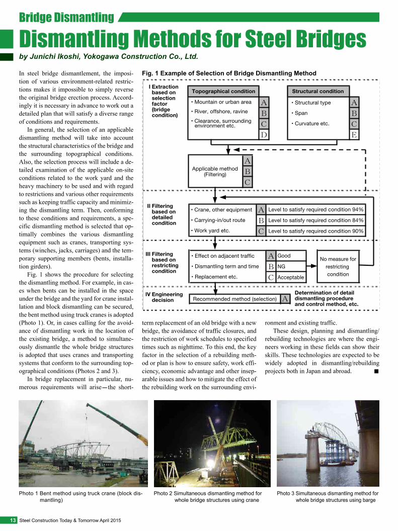
Fig. 1 Example of Selection of Bridge Dismantling MethodIn steel bridge dismantlement, the imposi-tion of various environment-related restric-tions makes it impossible to simply reverse the original bridge erection process. Accord-ingly it is necessary in advance to work out a detailed plan that will satisfy a diverse range of conditions and requirements.
In general, the selection of an applicable dismantling method will take into account the structural characteristics of the bridge and the surrounding topographical conditions. Also, the selection process will include a de-tailed examination of the applicable on-site conditions related to the work yard and the heavy machinery to be used and with regard to restrictions and various other requirements such as keeping traffic capacity and minimiz-ing the dismantling term. Then, conforming to these conditions and requirements, a spe-cific dismantling method is selected that op-timally combines the various dismantling equipment such as cranes, transporting sys-tems (winches, jacks, carriages) and the tem-porary supporting members (bents, installa-tion girders).
Fig. 1 shows the procedure for selecting the dismantling method. For example, in cas-es when bents can be installed in the space under the bridge and the yard for crane instal-lation and block dismantling can be secured, the bent method using truck cranes is adopted (Photo 1). Or, in cases calling for the avoid-ance of dismantling work in the location of the existing bridge, a method to simultane-ously dismantle the whole bridge structures is adopted that uses cranes and transporting systems that conform to the surrounding top-ographical conditions (Photos 2 and 3).
In bridge replacement in particular, nu-merous requirements will arise-the short-
term replacement of an old bridge with a new bridge, the avoidance of traffic closures, and the restriction of work schedules to specified times such as nighttime. To this end, the key factor in the selection of a rebuilding meth-od or plan is how to ensure safety, work effi-ciency, economic advantage and other insep-arable issues and how to mitigate the effect of the rebuilding work on the surrounding envi-
ronment and existing traffic.These design, planning and dismantling/
rebuilding technologies are where the engi-neers working in these fields can show their skills. These technologies are expected to be widely adopted in dismantling/rebuilding projects both in Japan and abroad. ■
by Junichi Ikoshi, Yokogawa Construction Co., Ltd.Dismantling Methods for Steel BridgesBridge Dismantling
• Mountain or urban area• River, offshore, ravine• Clearance, surrounding environment etc.
Topographical condition Structural condition
• Structural type
• Span
• Curvature etc.
• Crane, other equipment
• Carrying-in/out route
• Work yard etc.
Level to satisfy required condition 94%
Level to satisfy required condition 84%
Level to satisfy required condition 90%
Applicable method(Filtering)
Determination of detail dismantling procedure and control method, etc.
• Effect on adjacent traffic
• Dismantling term and time
• Replacement etc.
Recommended method (selection)
No measure forrestricting condition
Good
NG
Acceptable
Filtering based on detailed condition
Filtering based on restricting condition
Engineering decision
Extraction based on selection factor (bridge condition)
II
III
IV
I

The Hanoi-Ho Chi Minh Railway Line (ap-proximately 1,700 km in total length) has been deteriorating due to damage during the Vietnam War and to superannuation. In order to improve the safety of the bridges on the line, the project has been planned that pro-motes the improvement of 44 of the damaged railway bridges spanning rivers. The main aim of the project is to secure railway ser-vice safety, to enhance transport efficiency and to promote distribution services between the northern and southern areas of Vietnam, thereby contributing to the sustainable devel-opment of the national economy.
Between 2003 and 2007 improvements were completed on 19 bridges with Official Development Assistance (ODA) from Japan. This led to a considerable reduction of trav-el time from the conventional 36 hours to 29 hours between Hanoi and Ho Chi Minh City. The remaining ODA railway improvement projects are currently underway and will re-sult in improvements to all 44 bridges, fur-ther cutting the travel time to 24 hours.
The railway line is operated by means of a single track system. Of the bridges subjected to replacement, about 90% will be improved by the “replacement during window time” method in which the old bridge is replaced
with a new bridge while rail-way operations are tempo-rarily suspended for sever-al hours. The remaining 10% of bridges are to be newly in-stalled at the moved railway line in order to ease the rail-way curvature.
I was involved in the Con-struction Package No. 2 (CP2) and the Construction Package No. 1-D (CP1D).
The works on the No. 20 Truoi Bridge (CP2) located in the central part of Vietnam (Fig. 1) are introduced in this
No.20 Truoi Bridge
Before National Road No.1
National Road No.1
National Road No.1
National Road No.1
National Road No.1
Existing bridge
Transfer
Transfer of existing bridge(17 m)
Temporarily closed
Temporarily closed
Launching
Temporarily closed
New bridge
New bridge
After
Transfer
Transfer of new bridge(9 m)
Launching of new bridge(150 m)
14April 2015 Steel Construction Today & Tomorrow
Photo 1 Yard assembly of new bridge at No. 20 Truoi Bridge site
Fig. 1 Location of Replacement Project
Fig. 2 Replacement Steps Taken for No. 20 Truoi Bridge
by Masao Minagawa, Yokogawa Construction Co., Ltd.
Replacement of Railway Bridges in Vietnam
Replacement of Railway Bridge

article, which had been regarded as the most difficult in the 44 bridge improvement proj-ects. The works include the replacement of 2 continuous curved chord Warren trusses with 3 continuous Warren trusses.
Replacement of the No. 20 Truoi Bridge during Window TimeIn the conventional replacement during win-dow time, the new bridge is assembled in ad-vance at yard adjacent to the existing bridge on which the train runs, and on the day when railway operations are suspended, the exist-ing bridge is moved laterally to the opposite side of the yard and the new bridge is lateral-ly transferred to the vacant space and fixed.
However, in the No. 20 Truoi Bridge re-placement project, because a bridge on the national highway is located only 4 m away on the downstream side from the bridge, the nor-mal lateral transfer method could not be ap-plied. As a result of studies, a method was ad-opted by which the new bridge was assembled
in advance behind the existing bridge (Photo 1); then, on the day of replacement, a com-plex method was implemented combining the use of lateral and longitudinal transfers: lat-eral transfer of existing bridge→longitudinal transfer of new bridge→lateral transfer of new bridge (see Fig. 2 and Photos 2,3). The replacement of the bridge was to be complet-ed within 6 hours.
Lateral Transfer of BridgesIn recent bridge replacement projects in Ja-pan, the mainstream device in lateral trans-fers is the lateral-transfer jack, which does not allow significant deviation in moving and can easily make precise adjustments. On the other hand, in Vietnam, because of frequent power failures and difficulty of repairing hy-draulic system, the combined use of mechan-ical systems that require no electricity was adopted: TIRTANK (roller moving system) as the transfer device, manual winches on the tension side and TIRFOR (manual end-
less winch) on the running-away prevention side.
Further, direct fastened tracks (ballast-less tracks) were adopted for the No. 20 Truoi Bridge. So, time is needed to fasten the rails after a lateral transfer, and thus the rails were fastened in advance. Further, all simple truss bridges were connected at lower chords to mitigate the load work-ing on the direct rail fas-tening system during later-al transfer.
During lateral trans-
fer, because a difference in lateral tension between each bridge pier and the abutment of the new bridge may occur, control of the strokes (transfer amount) of the entire bridge structure became a key issue. In the project, the lateral transfer of the abutment parts with less traction force was preceded. And as a re-sult the entire bridge structure including the rails tended to cause angles at the bridge pier parts. In such case, in order to mitigate the ef-fect working on the rail-fastening device in a timely manner, the replacement work was conducted correcting the direction of move-ment of the TIRTANK.
Lowering of New Bridge onto the Bridge PiersAfter lateral transfer of the new bridge, the new bridge was lowered by a margin of the mechanical height of the TIRTANK (about 150 mm) in order to secure the prescribed rail height. During lowering operation, how to lower the new bridge onto the bridge piers at a low speed and how to synchronize the four support points became an important is-sue in order to mitigate the load working on the direct rail fastening system (Photo 4). Commonly in Japan, 4 interlocked electric pumps are used. However, because of the power supply situation stated earlier, a manu-al pump was arranged for each jack to imple-ment the lowering operation.
On the day of replacement, all operations went smoothly, and the replacement process of the No. 20 Truoi Bridge was successful-ly completed in 5 hours, 1 hour less than the planned 6-hour work time. ■
15 Steel Construction Today & Tomorrow April 2015
Photo 2 Lateral transfer of existing bridge at No. 20 Truoi Bridge site
Photo 3 Lateral transfer of new bridge at No. 20 Truoi Bridge Photo 4 Direct rail fastening system for directly laid railway

Due to the improvement of the Loop Road No. 2, one of the urban planning highway projects of the Tokyo metropolitan govern-ment, the Yaesu Route of the Metropolitan Expressway interferes with a section of the Loop Road No. 2 that is planned as an under-ground tunnel. This requires that the section of the Yaesu Route that is causing the inter-ference be rebuilt.
In the following, we primarily describe the removal of an existing bridge girder on the Yaesu Route that was ordered by Tokyo Metropolitan Expressway Company Limited (refer to Figs. 1 and 2).
Outline and Features of Existing Bridge Girder Removal• Removal of Concrete SlabsThe method selected for concrete slab re-moval took into account the resulting effect on vehicle traffic under the existing bridge and surrounding areas. Specifically, both dry-type wire saws and concrete cutters that do not require cooling water were adopted, and the concrete slabs were cut into blocks (2.1 m × 3.8 m) and removed to avoid onsite crush-ing.
In order to cut off the main girder from the slab in the box girder (non-composite girder) section, the low-noise, high-efficiency jack-up method was adopted (Photo 1). In the case of the plate girder (composite girder) section, the slabs on the main girder flange were left,
and the slabs between the girders were sus-pended using a crane and then were cut off.
• Removal of Existing Bridge Girder at Crossing
Diverse restrictions were imposed on the re-moval of the bridge girder installed at the Shiosakibashi crossing-reduction in the number of traffic closures, a narrow work space and a short 5-hour limit on traffic clo-sures, safety concerns and the effect of the work on the surrounding area. To cope with these conditions, the nighttime large-block removal method using transporters (multi-axle trucks) was adopted to remove the cen-ter span section of a 3-span continuous box girder (Fig. 3).
Two transporters, each with 8 axles, were aligned in a row, and lifters were installed on the transporters to lift the girder up and down (Fig. 4, Photo 2). To prepare for the use of transporters, advance track simulations were conducted to discover obstacles on the route and to take appropriate measures for re-moved girder transfer, and the running route was marked on the pavement.
When the center span section of the 3-span continuous box girder was first re-moved, the both side span became the simple girder, where the positive bending moment increased. As a result, the main girder stress
surpassed the allowable level. To cope with this, removal of pavement, slabs and concrete barrier curb preceded removal of the center-span girder.
The center-span girder (weight: about 250 tons; length: 26 m) to be removed was tem-porarily supported in advance using a setting beam, and while applying gas cutting, the girder was joined using a temporary splice plate. The temporary splice plate served as a safety measure for any possible fall of the setting beam and for suppressing the rap-id release of internal stress during gas cut-ting. Further, supposing the case in which the removal of the bolt joined to the splice plate might become difficult, a jack was in-stalled on both the upper and lower flanges
Shimbashi St.
Shiodome JCT
ShiodomeExit Shiodome
Entrance
Northbound
Southbound
ShiodomeTunnel
Loop Road No. 2 of Tokyo metropolitan government (under construction)
Yaesu Route of
Metropolitan Expressway
Shiosakibashi Crossing
Inner
Circu
lar R
oute
of
Metr
opoli
tan E
xpres
sway
Bridge rebuilding section
Before rebuilding
After rebuilding
Shinbashi Exit/Entrance
Shiodome underground parking lot
Shiodome underground parking lot
Planned section for tunnel of Loop Road No. 2
Planned section for tunnel of Loop Road No. 2
8010 pierRemoval
8008 pierRemoval
8007 pierRemoval
3-span continuous box girder Simple plate girderNorthboundSouthbound
Shiodome Exit/Entrance
Shinbashi Exit/Entrance
8010’ pierErection
8007’ pierErection
Rigid-frame bridge (simple steel deck box girder connected with steel piers)
Simple steel deck box girder
Simple steel deck plate girder
Shiodome Exit/Entrance
Removed slab Box girder upper flange
PC steelbar
Hydraulic jack
PC steel bar
16April 2015 Steel Construction Today & Tomorrow
Photo 1 Concrete slab removal by means of jack-up method
Fig. 1 Location of Rebuilding Project
Fig. 2 Outline of Rebuilding Project
by Yasuhiro Kakinuma and Atsushi Fukui, IHI Infrastructure Systems Co., Ltd.
Girder Removal in Rebuilding of Highway Bridge on Metropolitan Expressway
Rebuilding of Highway Bridge

of the girder (Fig. 5). The nighttime remov-al work was completed within the specified limit placed on traffic closures by capitaliz-ing on advance simulations and the provision of risk management countermeasures, and by reliable removal procedures.
Successful and Rapid Rebuilding of Bridge GirdersAfter removal of the existing bridge girders, the partial rebuilding of the Yaesu Route was completed 3 months earlier than the origi-nal schedule, largely due to the adoption of a large block erection method using transport-ers and to other new approaches applicable to construction cranes and temporary equip-ment (Photo 3).
Countermeasures against the superannu-ation of urban infrastructure are a pressing task. We will be glad if the rebuilding tech-nologies introduced above might serve as a reference in future large-scale bridge re-newal projects that are expected to grow in number. ■
Tension restraining
Side span
Removal girder
Cutting position
Compression restraining
Removal girder at center-span side
Side-span girder
Setting beam
Center hole jack (100 tons) × 2
Horizontal jack (100 tons) × 2
1300.0001
1486.0000
1486.0000
614.0000
∅150 ∅150
∅150
∅150
8061.0687
Goldhofer
84.9999
Goldhofer
84.9999
6300
2570
8870
3400
1515
257002000 21700 2000
4200 67701300
1300
1515
96001600 160012800
257002000 21700 2000
2570
8055 9600
8055 9600 8045
9583.51600 160015600
2800
Elevation (at the time of girder supporting)
Elevation (at the time of transport)
Existing girder before removal
Existing girder before removal
Existing girder before removal
Existing girder before removal
Girder support frame
Girder support frame
Beam for girder support
Hydraulic lifter
Hydraulic lifter
Power pack
Power pack
Hydraulic unit Lashing (axial direction)
5-axle truck 3-axle truck
④ ③ ① ②Removal order
Preceding construction of new bridge foundation Planned section for tunnel of
Loop Road No. 2 (separate work)*Removal of every main girder of 1 span**Removal of each main girder of 1 span
Removal by use of large-capacity crane**
Removal by use of large-capacity crane**
Large block removal by use of transporters*
17 Steel Construction Today & Tomorrow April 2015
Fig. 3 Girder Removal Method
Fig. 4 Lifting Up and Down of Girder by Use of Transporter
Fig. 5 Temporary Supporting Equipment
Photo 3 Full view after bridge rebuilding on Yaesu Route
Photo 2 Upper: Girder replacing condition Lower: Girder removal and transport

I assumed the post of President of the Japanese Society of Steel Construc-tion (JSSC) in June 2014.
JSSC was es-tablished in 1965
as an interdisciplinary organization that includes makers of steel and construction materials, construction companies, fab-ricators, consulting companies and aca-demia. JSSC celebrates its 50th anniversa-ry in 2015.
My primary task is to guide the en-hancement and expansion of JSSC’s inter-national activities and, secondarily, to pro-mote the transmission of Japan’s advanced steel construction technologies with the aim of creating secure and reliable soci-eties worldwide. A typical example of our tasks is the active involvement in the es-tablishment of common international stan-
dards such as those of the International Or-ganization for Standardization (ISO) in order to promote the worldwide spread and development of steel construction from a global perspective.
In May 2015, IABSE (International As-sociation for Bridge and Structural En-gineering) will hold IABSE Conference Nara 2015 in Japan. As a member of the JSSC secretariat responsible for the con-ference, I will extend active support and cooperation.
To these ends, I will make the utmost effort to nurture young researchers and en-gineers regardless of national origin so as to reinforce technological foundations re-lated to steel construction.
Taking the occasion of JSSC’s 50th an-niversary and capitalizing on the Society’s many achievements, I am preparing my-self to tackle these tasks one by one. Last-ly, I would like to ask for your continuous support and understanding of JSSC oper-ations.
Profile1972: Graduated from Faculty of Engineering, University of Tokyo1976: Ph. D (Civil Engineering), University of Waterloo1990: Professor, School of Engineering, Uni-versity of Tokyo2014: Distinguished Professor, Institute of Ad-vance Science, Yokohama National Universi-ty; Professor Emeritus, University of Tokyo
Major Awards• Medal with Purple Ribbon, Cabinet Office,
Government of Japan• Scanlan Medal, American Society of Civil En-
gineers (ASCE)• T.Y. Lin Medal, International Conference on
Bridge Maintenance And Safety• Nishino Medal, East Asia-Pacific Conference
of Structural Engineering and Construction• George Winter Award, ASCE
IABSE (International Association for Bridge and Structural Engineering) will hold IAB-SE Conference Nara 2015 for three days from May 13 to 15, 2015 in Nara, Japan. The main theme of the conference is “Elegance in Structures.” This conference will target elegant solutions and structures that dem-onstrate structural resistance to earthquakes and wind-including modeling and analysis methods for these structures, in addition to conventional structural forms.
A variety of events are planned for each day of the conference: delivery of keynote lectures, presentations of technical papers, commercial exhibitions, technical visits and other activities.
Taking this opportunity, all companies and organizations working in steel construc-tion are cordially invited to participate in the conference.
IABSE Conference Nara 2015• VenueNara Prefectural New Public Hall: Noh Theater, Conference Room, Reception Hall & GalleryURL:http://www.shinkokaido.jp/welcome/
• Exhibit application and expenseAccess to IABSE website (URL: http://www.iab-se.org/)
Major Events: Keynote Lectures• Mike Schlaich (Technische Universität Berlin,
Germany)• Ian Firth (Flint & Neill, COWI, UK)• Kaori Fujita (the University of Tokyo, Japan)• Joseph Tortorella (Robert Silman Associates,
USA)• Sun Limin (Tongji University, China)• Akio Kasuga (Sumitomo Mitsui Construction
Co., Ltd., Japan)• Masao Saito (Nihon University, Japan)• Ryoichi Kanno (Nippon Steel & Sumitomo Met-
al Corporation, Japan)• Woo-Jong Kim (DM Engineering Co., Ltd., Ko-
rea)
Young Engineers ProgramA workshop Elegance in Structures will be held at the conference venue on May 12 af-ternoon. It is basically a design competition for a pedestrian bridge in Nara: the workshop includes lectures by prominent engineers, re-
view of designs proposed by young engineers (35 years old or younger) and an award cer-emony.
18April 2015 Steel Construction Today & Tomorrow
Yozo Fujino, President, Japanese Society of Steel Construction
Message from New JSSC President
IABSE Conference Nara 2015
Messages from New President and Committee Chairman ・ JSSC Operations

JSSC Symposium 2014 on Structural Steel Construction, sponsored by the Japanese So-ciety of Steel Construction, was held on No-vember 13 and 14, 2014 in Tokyo and served as a useful venue for researchers including graduate students, engineers of steelmakers and steel users, JSSC members and others working in steel construction. A variety of events were held, centering around the Academy Session where theses lec-tures were given by contributors to the JSSC annual journal Steel Construction Engineer-
ing and the Memorial Lecture Meeting where the winners of JSSC commendations for out-standing achievement in 2014 made presen-tations (for the prize-winning works, refer to pages 1~6). Also featured were lecture meet-ings and panel discussions that aimed to com-prehensively and functionally link the activi-ties of JSSC’s various committees-Stainless Steel Session: presentation titled “Outline of Dual-phase Stainless Steel and Corresponding Applications;” Engineering Session: presenta-tion titled “From the Age of Construction to
the Age of Utilization-Urban Renewal and Steel Structures;” and International Session: presentation titled “Tackling Globalization.”
Prize winners of JSSC commendations for out-standing achievements in 2014
JSSC Symposium 2014 on Structural Steel Construction
I have assumed the post of Chairman of the Internation-al Committee of the Japanese Society of Steel Construction (JSSC).
Starting with is-sue No. 26 of Steel Construction Today & To-morrow, published in 2009, our Internation-al Committee has been responsible for the editorial planning of one of the three issues that are published annually. Since its inaugu-ration, JSSC has conducted wide-ranging ac-tivities in the form of surveys, research and technological development aimed at promot-ing the spread of steel construction and at im-
proving associated technologies, and at the same time it has extended cooperation to re-lated organizations overseas.
Following the merger of JSSC with the Stainless Steel Building Association of Japan in 2010, JSSC’s field of operation expanded to include not only carbon steel but also high-ly corrosion-resistant stainless steel. Conse-quently, we intend to actively transmit infor-mation throughout the world that is related to a wider range of steel construction areas.
As was true in issue No. 41, the previous special issue of the JSSC for which our com-mittee was responsible, our current issue, No. 44, introduces the excellent works and the-ses that have received a JSSC prize of com-mendation for outstanding achievement in 2014. In addition, this issue features “demo-lition methods for steel structures,” particu-larly a demolition method for high-rise build-
ings and steel bridges. It also reports on the 2013 JSSC Symposium on Structural Steel Construction and other major operations.
The International Committee, while work-ing on multi-faceted responses to the interna-tionalization of steel construction specifica-tions and standards, promotes exchanges of technical information and personnel between Japan and overseas organizations. As one as-pect of these operations, we are attempting with this issue to inform our readers of JSSC operations, trends in steel construction, and the technologies and technological develop-ments relevant to the planning, design, and building of steel structures in Japan.
If you wish to obtain more detailed infor-mation about the various articles contained in this issue or to receive related technical infor-mation, please do not hesitate to contact the JSSC secretariat ([email protected]).
Kuniei Nogami, Chairman, International Committee (Professor, Tokyo Metropolitan University)
Message from New Chairman of International Committee
STEEL CONSTRUCTION TODAY & TOMORROW
Japanese Society of Steel ConstructionYotsuya Mitsubishi Bldg. 9th Fl., 3-2-1 Yotsuya, Shinjuku-ku, Tokyo 160-0004, JapanPhone: 81-3-5919-1535 Fax: 81-3-5919-1536URL http://www.jssc.or.jp/english/index.html
The Japan Iron and Steel Federation3-2-10, Nihonbashi Kayabacho, Chuo-ku, Tokyo 103-0025, JapanPhone: 81-3-3669-4815 Fax: 81-3-3667-0245URL http://www.jisf.or.jp/en/index.html
Published jointly by Committee on Overseas Market Promotion, The Japan Iron and Steel FederationChairman (Editor): Keiji Ando
Edited by
Publ ished three t imes per year, STEEL CONSTRUCTION TODAY & TOMORROW is circulated to interested persons, companies and public organizations to promote a better understanding of steel products and their application in the construction industry. Any part of this publication may be reproduced with our permission. To download content (PDF format), please go our website at: http://www.jisf.or.jp/en/activitity/sctt/index.html. We welcome your comments about the publication and ask that you contact us at: [email protected].
© 2015 The Japan Iron and Steel Federation
Request for Participation in Survey of Steel Construction Today & TomorrowThe survey forms are available in two formats:• At the JISF Website
• Printed Form for FaxingA survey form is enclosed in the magazine sent to our regular subscriber. After filling-in, please fax to +81-3-3667-0245.→Click on the tab for Steel Construction Today & Tomorrow
→Click the survey form
→Enter “jisf” in the search window of your internet browser