nmea reference manual - velero olaje time, position and fix type data gll latitude, longitude, utc...
TRANSCRIPT

MN000315E © 2006 Navman New Zealand. All rights reserved. Proprietary information and specifications subject to change without notice.
This document contains proprietary information to SiRF Technology, Inc. and has been reproduced with permission of SiRF Technology Holdings, Inc.
NMEA reference manual

�MN000315E © 2006 Navman New Zealand. All rights reserved. Proprietary information and specifications subject to change without notice.
Contents1. NMEA output messages .....................................................................................4
GGA —Global Positioning System Fixed Data................................................................... 5
GLL—Geographic Position - Latitude/Longitude................................................................ 6
GSA—GNSS DOP and Active Satellites............................................................................ 7
GSV—GNSS Satellites in View........................................................................................... 8
MSS—MSK Receiver Signal.............................................................................................. 8
RMC—Recommended Minimum Specific GNSS Data...................................................... 9
VTG—Course Over Ground and Ground Speed................................................................ 9
ZDA—SiRF Timing Message.............................................................................................10
150—OkToSend.................................................................................................................10
2. NMEA input messages ..................................................................................... 11Transport.Message............................................................................................................11
100—SetSerialPort ...........................................................................................................12
101—NavigationInitialization..............................................................................................13
102—SetDGPSPort ..........................................................................................................13
103—Query/Rate Control..................................................................................................14
104—LLANavigationInitialization.......................................................................................15
105—Development Data On/Off........................................................................................16
106—Select Datum............................................................................................................16
MSK—MSK Receiver Interface.........................................................................................17
3. Navman proprietary messages ....................................................................... 183.1.Low.power.mode.messages.........................................................................................18
3.1.1 Low power configuration.......................................................................................183.1.2 Low power acquisition configuration....................................................................18

�MN000315E © 2006 Navman New Zealand. All rights reserved. Proprietary information and specifications subject to change without notice.
TablesTable 1-1: NMEA output messages..................................................................................... 4
Table 1-2: Supported NMEA output messages................................................................... 4
Table 1-3: GGA data format................................................................................................ 5
Table 1-4: GGA position fix quality indicator....................................................................... 5
Table 1-5: GLL data format................................................................................................. 6
Table 1-6: GSA data format................................................................................................ 7
Table 1-7: Mode 1 GSA data format.................................................................................... 7
Table 1-8: Mode 2 GSA data format................................................................................... 7
Table 1-9: GSV data format................................................................................................. 8
Table 1-10: MSS data format............................................................................................... 8
Table 1-11: RMC data format............................................................................................... 9
Table 1-12: VTG data format............................................................................................... 9
Table 1-13: ZDA data format..............................................................................................10
Table 1-14: OkToSend message data format.....................................................................10
Table 2-1: NMEA input messages......................................................................................11
Table 2-2: Supported NMEA input messages....................................................................12
Table 2-3: Set serial port data format.................................................................................12
Table 2-4: Navigation initialization data format..................................................................13
Table 2-5: Reset configuration...........................................................................................13
Table 2-6: Set DGPS port data format...............................................................................13
Table 2-7: Query/rate control data format...........................................................................14
Table 2-8: Messages..........................................................................................................14
Table 2-9: LLA navigation initialization data format............................................................15
Table 2-10: Reset configuration..........................................................................................15
Table 2-11: Development data on/off data format...............................................................16
Table 2-12: Select datum data format.................................................................................16
Table 2-13: RMC data format.............................................................................................17
Table 3-1: Low power modes message values..................................................................18
Table 3-2: Low power acquisition input values...................................................................18

�MN000315E © 2006 Navman New Zealand. All rights reserved. Proprietary information and specifications subject to change without notice.
1. NMEA output messagesThe table below lists each of the NMEA output messages specifically developed and defined by SiRF for use within SiRF products.
Option Description
GGA Time, position and fix type data
GLL Latitude, longitude, UTC time of position fix and status
GSA GPS receiver operating mode, satellites used in the position solution, and DOP values
GSV The number of GPS satellites in view satellite ID numbers, elevation, azimuth, and SNR values
MSS Signal-to-noise ratio, signal strength, frequency, and bit rate from a radio-beacon receiver
RMC Time, date, position, course and speed data
VTG Course and speed information relative to the ground
ZDA ZDAPPS timing message (synchronized to PPS)
150 OK to send message
Table 1-1: NMEA output messages
A full description of the listed NMEA messages are provided in the following sections. Table 1-2 provides a summary of SiRF NMEA output messages supported by the specific SiRF platforms.
SiRF software options
Message ID GSW2 SiRFDRive SiRFXTrac
GGA
GLL
GSA
GSV
MSS X X
RMC
VTG
ZTA X X
150 X X
Table 1-2: Supported NMEA output messages
All software options output NMEA version 2.20.
�MN000315E © 2006 Navman New Zealand. All rights reserved. Proprietary information and specifications subject to change without notice.
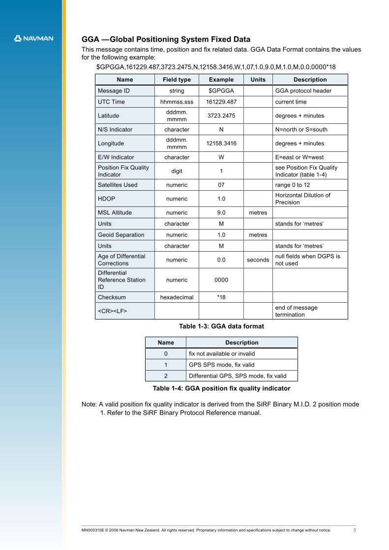
GGA —Global Positioning System Fixed DataThis message contains time, position and fix related data. GGA Data Format contains the values for the following example:
$GPGGA,161229.487,3723.2475,N,12158.3416,W,1,07,1.0,9.0,M,1.0,M,0.0,0000*18
Name Field type Example Units Description
Message ID string $GPGGA GGA.protocol.header
UTC Time hhmmss.sss 161229.487 current time
Latitude dddmm.mmmm 3723.2475 degrees + minutes
N/S Indicator character N N=north or S=south
Longitude dddmm.mmmm 12158.3416 degrees + minutes
E/W Indicator character W E=east or W=west
Position Fix Quality Indicator digit 1 see Position Fix Quality
Indicator (table 1-4)
Satellites Used numeric 07 range.0.to.12
HDOP numeric 1.0 Horizontal Dilution of Precision
MSL Altitude numeric 9.0 metres
Units character M stands.for.‘metres’
Geoid Separation numeric 1.0 metres
Units character M stands.for.‘metres’
Age.of.Differential.Corrections numeric 0.0 seconds null fields when DGPS is
not usedDifferential.Reference Station ID
numeric 0000
Checksum hexadecimal *18
<CR><LF> end.of.message.termination
Table 1-3: GGA data format
Name Description
0 fix not available or invalid
1 GPS SPS mode, fix valid
2 Differential GPS, SPS mode, fix valid
Table 1-4: GGA position fix quality indicator
Note: A valid position fix quality indicator is derived from the SiRF Binary M.I.D. 2 position mode 1. Refer to the SiRF Binary Protocol Reference manual.
�MN000315E © 2006 Navman New Zealand. All rights reserved. Proprietary information and specifications subject to change without notice.
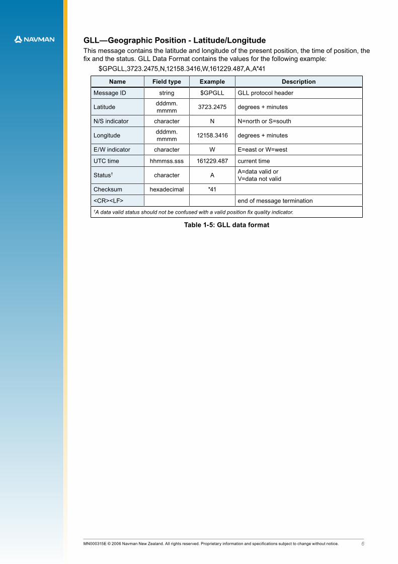
GLL—Geographic Position - Latitude/LongitudeThis message contains the latitude and longitude of the present position, the time of position, the fix and the status. GLL Data Format contains the values for the following example:
$GPGLL,3723.2475,N,12158.3416,W,161229.487,A,A*41
Name Field type Example Description
Message ID string $GPGLL GLL.protocol.header
Latitude dddmm.mmmm 3723.2475 degrees + minutes
N/S indicator character N N=north or S=south
Longitude dddmm.mmmm 12158.3416 degrees + minutes
E/W indicator character W E=east or W=west
UTC time hhmmss.sss 161229.487 current time
Status† character A A=data.valid.or..V=data not valid
Checksum hexadecimal *41
<CR><LF> end.of.message.termination†A data valid status should not be confused with a valid position fix quality indicator.
Table 1-5: GLL data format

�MN000315E © 2006 Navman New Zealand. All rights reserved. Proprietary information and specifications subject to change without notice.
GSA—GNSS DOP and Active SatellitesThis message contains the receiver’s operating mode, satellites used for navigation,and DOP values. GSA Data Format contains the values for the following example:
$GPGSA,A,3,07,02,26,27,09,04,15, , , , , ,1.8,1.0,1.5*33
Name Field type Example Description
Message ID string $GPGSA GSA protocol header
Mode.1 character A see Mode 1 (table 1-7)
Mode.2 digit 3 see Mode 2 (table 1-8)
Satellite Used† numeric 07 Sv on Channel 1
Satellite Used† numeric 02 Sv on Channel 2
.... ....
Satellite Used† numeric Sv on Channel 12
PDOP numeric 1.8 Position Dilution of Precision
HDOP numeric 1.0 Horizontal Dilution of Precision
VDOP numeric 1.5 Vertical Dilution of Precision
Checksum hexadecimal *33
<CR> <LF> end.of.message.termination†Satellite used in solution
Table 1-6: GSA data format
Value Description
M Manual – forced to operate in 2D or 3D mode
A 2D Automatic – allowed to automatically switch 2D/3D
Table 1-7: Mode 1 GSA data format
Value Description
1 fix not available
2 2D (<4 SVs used)
3 3D (>3 SVs used)
Table 1-8: Mode 2 GSA data format
�MN000315E © 2006 Navman New Zealand. All rights reserved. Proprietary information and specifications subject to change without notice.
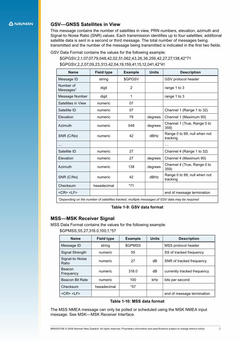
GSV—GNSS Satellites in ViewThis message contains the number of satellites in view, PRN numbers, elevation, azimuth and Signal-to-Noise Ratio (SNR) values. Each transmission identifies up to four satellites; additional satellite data is sent in a second or third message. The total number of messages being transmitted and the number of the message being transmitted is indicated in the first two fields.
GSV Data Format contains the values for the following example:$GPGSV,2,1,07,07,79,048,42,02,51,062,43,26,36,256,42,27,27,138,42*71$GPGSV,2,2,07,09,23,313,42,04,19,159,41,15,12,041,42*41
Name Field type Example Units Description
Message ID string $GPGSV GSV protocol header
Number of Messages† digit 2 range.1.to.3
Message Number digit 1 range.1.to.3
Satellites in View numeric 07
Satellite ID numeric 07 Channel 1 (Range 1 to 32)
Elevation numeric 79 degrees Channel 1 (Maximum 90)
Azimuth numeric 048 degrees Channel 1 (True, Range 0 to 359)
SNR (C/No) numeric 42 dBHz Range 0 to 99, null when not tracking
.... ....
Satellite ID numeric 27 Channel 4 (Range 1 to 32)
Elevation numeric 27 degrees Channel 4 (Maximum 90)
Azimuth numeric 138 degrees Channel 4 (True, Range 0 to 359)
SNR (C/No) numeric 42 dBHz Range 0 to 99, null when not tracking
Checksum hexadecimal *71
<CR> <LF> end.of.message.termination†Depending on the number of satellites tracked, multiple messages of GSV data may be required
Table 1-9: GSV data format
MSS—MSK Receiver SignalMSS Data Format contains the values for the following example:
$GPMSS,55,27,318.0,100,1,*57
Name Field type Example Units Description
Message ID string $GPMSS MSS protocol header
Signal Strength numeric 55 SS of tracked frequency
Signal-to-Noise Ratio numeric 27 dB SNR of tracked frequency
Beacon Frequency numeric 318.0 dB currently tracked frequency
Beacon Bit Rate numeric 100 kHz bits per second
Checksum hexadecimal *57
<CR> <LF> end.of.message.termination
Table 1-10: MSS data format
The MSS NMEA message can only be polled or scheduled using the MSK NMEA input message. See MSK—MSK Receiver Interface.

�MN000315E © 2006 Navman New Zealand. All rights reserved. Proprietary information and specifications subject to change without notice.
RMC—Recommended Minimum Specific GNSS DataThis message contains time, date, position, course, and speed data. The fields in this message always contain data even when the receiver is not navigating. This allows user-initialised, stored or default values to be displayed before a solution is obtained.
RMC Data Format contains the values for the following example:$GPRMC,161229.487,A,3723.2475,N,12158.3416,W,0.130,309.62,120598,23.1,E*10
Name Field type Example Units Description
Message ID string $GPRMC RMC protocol header
UTC Time hhmmss.sss 161229.487 current time
Status† character A A=data.valid.or..V=data not valid
Latitude ddmm.mmmm 3723.2475 degrees + minutes
N/S indicator character N N=north or S=south
Longitude ddmm.mmmm 12158.3416 degrees + minutes
E/W indicator character W E=east or W=west
Speed over ground numeric 0.130
Course over ground numeric 309.62 true
Date ddmmyy 120598 current date
Magnetic.variation numeric 23.1 degrees
E/W indicator character E E=east or W=west
Checksum hexadecimal *10
<CR> <LF> end.of.message.termination†A data valid status should not be confused with a valid position fix quality indicator.
Table 1-11: RMC data format
VTG—Course Over Ground and Ground SpeedThis message contains the course over ground (true and magnetic) and speed relative to the ground. VTG Data Format contains the values for the following example:
$GPVTG,309.62,T,286.52,M,0.13,N,0.20,K,A*23
Name Field type Example Units Description
Message ID string $GPVTG RMC protocol header
Course numeric 309.62 degrees measured heading
Reference character T true
Course numeric 286.52 degrees measured heading
Reference character M magnetic
Speed numeric 0.13 knots measured horizontal speed
Units character N knots
Speed numeric 0.20 km/h measured horizontal speed
Units character K kilometres per hour
Checksum hexadecimal *23
<CR> <LF> end.of.message.termination
Table 1-12: VTG data format
The precision of the speed and heading fields are always consistent, having a 2 decimal place precision. Please note that the NMEA standard allows these fields to be given out without digits after.the.decimal.point.
10MN000315E © 2006 Navman New Zealand. All rights reserved. Proprietary information and specifications subject to change without notice.
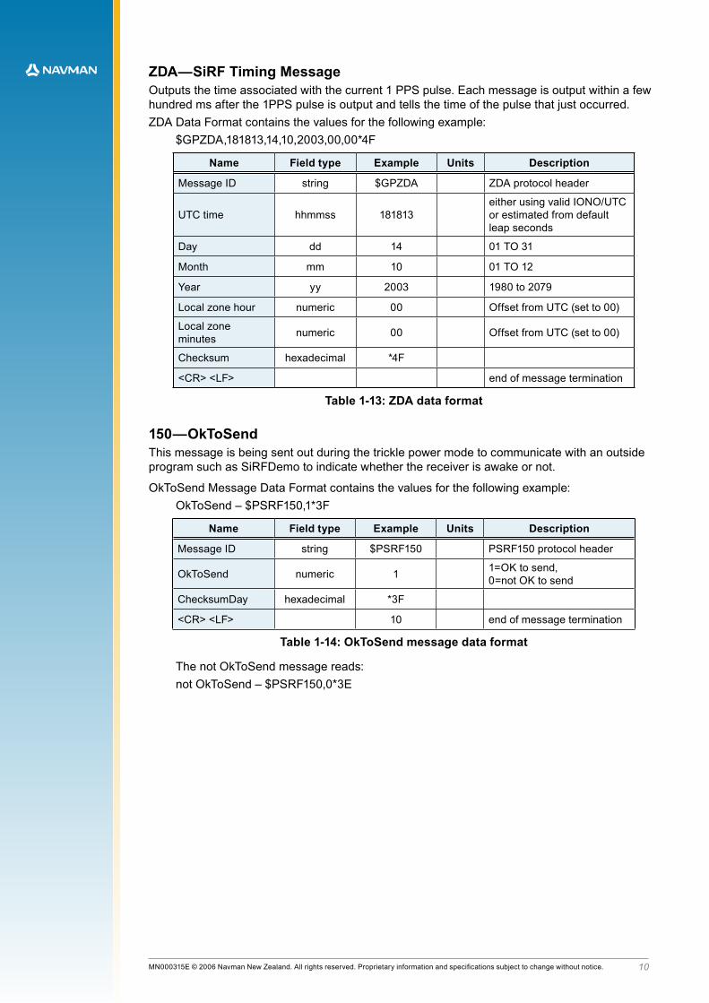
ZDA—SiRF Timing MessageOutputs the time associated with the current 1 PPS pulse. Each message is output within a few hundred ms after the 1PPS pulse is output and tells the time of the pulse that just occurred. ZDA Data Format contains the values for the following example:
$GPZDA,181813,14,10,2003,00,00*4F
Name Field type Example Units Description
Message ID string $GPZDA ZDA.protocol.header
UTC time hhmmss 181813either using valid IONO/UTC or estimated from default leap.seconds
Day dd 14 01 TO 31
Month mm 10 01 TO 12
Year yy 2003 1980.to.2079
Local zone hour numeric 00 Offset from UTC (set to 00)
Local zone minutes numeric 00 Offset from UTC (set to 00)
Checksum hexadecimal *4F
<CR> <LF> end.of.message.termination
Table 1-13: ZDA data format
150—OkToSendThis message is being sent out during the trickle power mode to communicate with an outside program such as SiRFDemo to indicate whether the receiver is awake or not.
OkToSend Message Data Format contains the values for the following example:OkToSend – $PSRF150,1*3F
Name Field type Example Units Description
Message ID string $PSRF150 PSRF150 protocol header
OkToSend numeric 1 1=OK to send, .0=not OK to send
ChecksumDay hexadecimal *3F
<CR> <LF> 10 end.of.message.termination
Table 1-14: OkToSend message data format
The not OkToSend message reads:not OkToSend – $PSRF150,0*3E
11MN000315E © 2006 Navman New Zealand. All rights reserved. Proprietary information and specifications subject to change without notice.
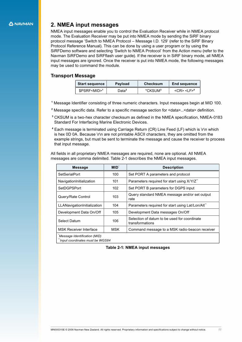
2. NMEA input messagesNMEA input messages enable you to control the Evaluation Receiver while in NMEA protocol mode. The Evaluation Receiver may be put into NMEA mode by sending the SiRF binary protocol message ‘Switch to NMEA Protocol – Message I.D. 129’ (refer to the SiRF Binary Protocol Reference Manual). This can be done by using a user program or by using the SiRFDemo software and selecting ‘Switch to NMEA Protocol’ from the Action menu (refer to the Navman SiRFDemo and SiRFflash user guide). If the receiver is in SiRF binary mode, all NMEA input messages are ignored. Once the receiver is put into NMEA mode, the following messages may be used to command the module.
Transport MessageStart sequence Payload Checksum End sequence
$PSRF<MID>1 Data2 *CKSUM3 <CR> <LF>4
1 Message Identifier consisting of three numeric characters. Input messages begin at MID 100.2 Message specific data. Refer to a specific message section for <data>...<data> definition.3 CKSUM is a two-hex character checksum as defined in the NMEA specification, NMEA-0183
Standard For Interfacing Marine Electronic Devices.4 Each message is terminated using Carriage Return (CR) Line Feed (LF) which is \r\n which
is hex 0D 0A. Because \r\n are not printable ASCII characters, they are omitted from the example strings, but must be sent to terminate the message and cause the receiver to process that input message.
All fields in all proprietary NMEA messages are required, none are optional. All NMEA messages are comma delimited. Table 2-1 describes the NMEA input messages.
Message MID* Description
SetSerialPort 100 Set PORT A parameters and protocol
NavigationInitialization 101 Parameters required for start using X/Y/Z**
SetDGPSPort 102 Set PORT B parameters for DGPS input
Query/Rate Control 103 Query standard NMEA message and/or set output rate
LLANavigationInitialization 104 Parameters required for start using Lat/Lon/Alt**
Development Data On/Off 105 Development Data messages On/Off
Select Datum 106 Selection of datum to be used for coordinate transformations
MSK Receiver Interface MSK Command message to a MSK radio-beacon receiver*Message Identification (MID)**Input coordinates must be WGS84
Table 2-1: NMEA input messages

1�MN000315E © 2006 Navman New Zealand. All rights reserved. Proprietary information and specifications subject to change without notice.
NMEA input messages 100 to 106 are SiRF proprietary NMEA messages. The MSK NMEA string is as defined by the NMEA 0183 standard.
Table 2-2 provides a summary of supported SiRF NMEA input messages by the specific SiRF platforms.
Message IDSiRF software options
GSW2 SiRFDRive SiRFXTrac
100
101 X
102 X
103
104 X
105
106
MSK X
Table 2-2: Supported NMEA input messages
100—SetSerialPort This command message is used to set the protocol (SiRF binary or NMEA) and/or the communication parameters (baud, data bits, stop bits, and parity). Generally, this command is used to switch the module back to SiRF binary protocol mode where a more extensive command message set is available. When a valid message is received, the parameters are stored in battery-backed SRAM and the Evaluation Receiver restarts using the saved parameters..
This message contains the input values for the following example:Switch to SiRF binary protocol at 9600,8,N,1 – $PSRF100,0,9600,8,1,0*0C
Name Field type Example Description
Message ID string $PSRF100 PSRF100 protocol header
Protocol digit 0 0=SiRF binary†, 1=NMEA
Baud numeric 9600 4800, 9600, 19200, 38400
Data Bits digit 8 7, 8
Stop Bits digit 1 0, 1
Parity digit 0 0=None, 1=Odd, 2=Even
Checksum hexadecimal *0C
<CR> <LF> end.of.message.termination†SiRF protocol is only valid for 8 data bits, 1stop bit, and no parity.
Table 2-3: Set serial port data format

1�MN000315E © 2006 Navman New Zealand. All rights reserved. Proprietary information and specifications subject to change without notice.
101—NavigationInitializationThis command is used to initialize the Evaluation Receiver by providing current position (in X, Y, Z coordinates), clock offset, and time. This enables the Evaluation Receiver to search for the correct satellite signals at the correct signal parameters. Correct initialization parameters enable the Evaluation Receiver to acquire signals quickly.
This message contains the input values for the following example:Start using known position and time – $PSRF101,-2686700,-304200,3851624,96000,497260,921,12,3*1C
Name Field type Example Units Description
Message ID string $PSRF101 PSRF101 protocol header
ECEF X numeric -2686700 metres X coordinate position
ECEF Y numeric -304200 metres Y.coordinate.position
ECEF Z numeric 3851624 metres Z.coordinate.position
Clk Offset numeric 96000 Hz clock offset of the evaluation receiver
Time Of Week numeric 497260 seconds GPS Time Of Week
WeekNo numeric 921 GPS Week Number
Channel Count numeric 12 Range 1 to 12
Reset Cfg numeric 3 See Reset Configuration (table 2-5)
Checksum hexadecimal *1C
<CR> <LF> end.of.message.termination
Table 2-4: Navigation initialization data format
No. Description
1 Hot Start— All data valid
2 Warm Start—Ephemeris cleared
3 Warm Start (with Init)—Ephemeris cleared, initialization data loaded
4 Cold Start—Clears all data in memory
8 Clear Memory—Clears all data in memory and resets the receiver back to factory defaults
Table 2-5: Reset configuration
102—SetDGPSPort This command is used to control the serial port used to receive RTCM differential corrections. Differential receivers may output corrections using different communication parameters. If a DGPS receiver is used that has different communication parameters, use this command to allow the receiver to correctly decode the data. When a valid message is received, the parameters are stored in battery-backed SRAM and the receiver restarts using the saved parameters.
This message contains the input values for the following example:Set DGPS Port to be 9600,8,N,1 – $PSRF102,9600,8,1,0*12
Name Field type Example Description
Message ID string $PSRF102 PSRF102 protocol header
Baud numeric 9600 4800, 9600, 19200, 38400
Data Bits digit 8 7, 8
Stop Bits digit 1 0, 1
Parity digit 0 0=None, 1=Odd, 2=Even
Checksum hexadecimal *12
<CR> <LF> end.of.message.termination
Table 2-6: Set DGPS port data format
1�MN000315E © 2006 Navman New Zealand. All rights reserved. Proprietary information and specifications subject to change without notice.
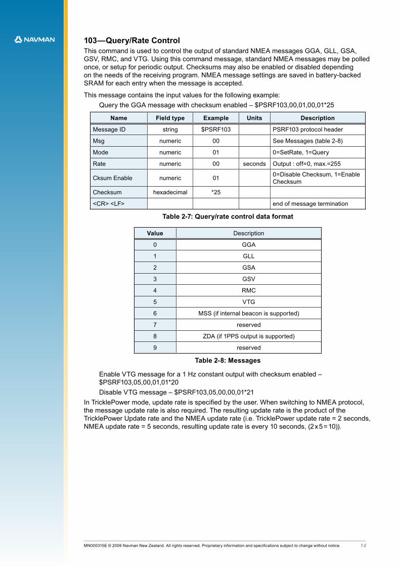
103—Query/Rate ControlThis command is used to control the output of standard NMEA messages GGA, GLL, GSA, GSV, RMC, and VTG. Using this command message, standard NMEA messages may be polled once, or setup for periodic output. Checksums may also be enabled or disabled depending on the needs of the receiving program. NMEA message settings are saved in battery-backed SRAM for each entry when the message is accepted.
This message contains the input values for the following example:Query the GGA message with checksum enabled – $PSRF103,00,01,00,01*25
Name Field type Example Units Description
Message ID string $PSRF103 PSRF103 protocol header
Msg numeric 00 See Messages (table 2-8)
Mode numeric 01 0=SetRate, 1=Query
Rate numeric 00 seconds Output : off=0, max.=255
Cksum Enable numeric 01 0=Disable Checksum, 1=Enable Checksum
Checksum hexadecimal *25
<CR> <LF> end.of.message.termination
Table 2-7: Query/rate control data format
Value Description
0 GGA
1 GLL
2 GSA
3 GSV
4 RMC
5 VTG
6 MSS (if internal beacon is supported)
7 reserved
8 ZDA (if 1PPS output is supported)
9 reserved
Table 2-8: Messages
Enable VTG message for a 1 Hz constant output with checksum enabled – $PSRF103,05,00,01,01*20Disable VTG message – $PSRF103,05,00,00,01*21
In TricklePower mode, update rate is specified by the user. When switching to NMEA protocol, the message update rate is also required. The resulting update rate is the product of the TricklePower Update rate and the NMEA update rate (i.e. TricklePower update rate = 2 seconds, NMEA update rate = 5 seconds, resulting update rate is every 10 seconds, (2 x 5 = 10)).

1�MN000315E © 2006 Navman New Zealand. All rights reserved. Proprietary information and specifications subject to change without notice.
104—LLANavigationInitializationThis command is used to initialize the Evaluation Receiver by providing current position (in latitude, longitude, and altitude coordinates), clock offset, and time. This enables the receiver to search for the correct satellite signals at the correct signal parameters. Correct initialization parameters enable the receiver to acquire signals quickly.
This message contains the input values for the following example:Start using known position and time –
$PSRF104,37.3875111,-121.97232,0,96000,237759,1946,12,1*07
Name Field type Example Units Description
Message ID string $PSRF104 PSRF104 protocol header
Lat numeric 37.3875111 degrees Latitude position (Range 90 to -90)
Long numeric -121.97232 degrees Longitude position (Range 180 to -180)
Alt numeric 0 metres Altitude position
Clk Offset numeric 96000 Hz Clock Offset of the Evaluation Receiver†
Time Of Week numeric 237759 seconds GPS Time Of Week
Week No numeric 1946 Extended GPS Week Number (1024 added)
Channel Count numeric 12 Range 1 to 12
Reset Cfg numeric 1 See Reset Configuration (table 2-10)
Checksum hexadecimal *07
<CR> <LF> end.of.message.termination
†Use 0 for last saved value if available. If this is unavailable, a default value of 96 000 is used.
Table 2-9: LLA navigation initialization data format
Hex Description
1 Hot Start— All data valid
2 Warm Start—Ephemeris cleared
3 Warm Start (with Init)—Ephemeris cleared, initialization data loaded
4 Cold Start—Clears all data in memory
8 Clear Memory—Clears all data in memory and resets receiver back to factory defaults
Table 2-10: Reset configuration

1�MN000315E © 2006 Navman New Zealand. All rights reserved. Proprietary information and specifications subject to change without notice.
105—Development Data On/OffUse this command to enable development data information if you are having trouble getting commands accepted. Invalid commands generate debug information that enables the user to determine the source of the command rejection. Common reasons for input command rejection are invalid checksum or parameter out of specified range.
This message contains the input values for the following example:Debug On – $PSRF105,1*3E
Name Field type Example Description
Message ID string $PSRF105 PSRF105 protocol header
Debug digit 1 0=Off, 1=On
Checksum hexadecimal *3E
<CR> <LF> end.of.message.termination
Table 2-11: Development data on/off data format
Debug Off – $PSRF105,0*3F
106—Select DatumGPS receivers perform initial position and velocity calculations using an earth-centered earth-fixed (ECEF) coordinate system. Results may be converted to an earth model (geoid) defined by the selected datum. The default datum is WGS 84 (World Geodetic System 1984) which provides a worldwide common grid system that may be translated into local coordinate systems or map datums. (Local map datums are a best fit to the local shape of the earth and not valid worldwide.)
This Message contains the input values for the following examples:Datum select TOKYO_MEAN – $PSRF106,178*32
Name Field type Example Description
Message ID string $PSRF106 PSRF106 protocol header
Datum numeric 178
21=WGS84178=TOKYO_MEAN179=TOKYO_JAPAN180=TOKYO_KOREA181=TOKYO_OKINAWA
Checksum hexadecimal *32
<CR> <LF> end.of.message.termination
Table 2-12: Select datum data format
1�MN000315E © 2006 Navman New Zealand. All rights reserved. Proprietary information and specifications subject to change without notice.
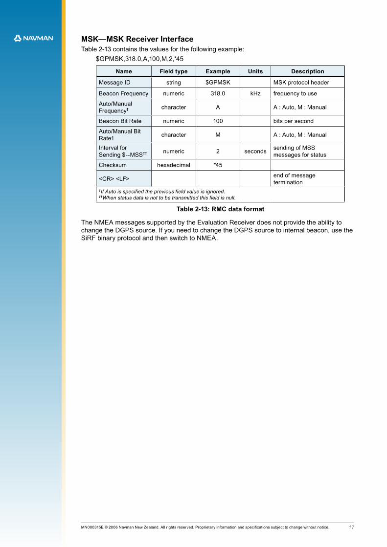
MSK—MSK Receiver InterfaceTable 2-13 contains the values for the following example:
$GPMSK,318.0,A,100,M,2,*45
Name Field type Example Units Description
Message ID string $GPMSK MSK protocol header
Beacon Frequency numeric 318.0 kHz frequency to use
Auto/Manual Frequency† character A A : Auto, M : Manual
Beacon Bit Rate numeric 100 bits per second
Auto/Manual Bit Rate1 character M A : Auto, M : Manual
Interval for Sending $--MSS†† numeric 2 seconds sending of MSS
messages for status
Checksum hexadecimal *45
<CR> <LF> end.of.message.termination
†If Auto is specified the previous field value is ignored.††When status data is not to be transmitted this field is null.
Table 2-13: RMC data format
The NMEA messages supported by the Evaluation Receiver does not provide the ability to change the DGPS source. If you need to change the DGPS source to internal beacon, use the SiRF binary protocol and then switch to NMEA.

1�MN000315E © 2006 Navman New Zealand. All rights reserved. Proprietary information and specifications subject to change without notice.
3. Navman proprietary messages3.1 Low power mode messagesNavman has added a number of proprietary NMEA input messages to configure the TricklePowerTM and Push-To-FixTM.modes.
3.1.1 Low power configurationThe following message sets the receiver to low power mode:
$PSRF151,a,bbbb,cccc[*CS]where:
Field Description
a Push-To-Fix* (1=on, 0=off)
b TricklePower duty cycle (parts per thousand)
c TricklePower on time (milliseconds)
*Note that Push-To-FixTM does not require fields b and c so they may be left blank
Table 3-1: Low power modes message values
This message is the NMEA equivalent of the SiRF Binary input message ID 151.
System response:$PTTK,LPSET,a,bbbb,cccc*CS
The updated values returned by the system are as described in Table 3-1.
3.1.2 Low power acquisition configurationThe following message sets the acquisition parameters of the low power mode:
$PSRF167,aaaa,bbbb,cccc,d[*CS]where:
Field Description
a maximum off time (milliseconds)
b maximum search time (milliseconds)
c Push-To-Fix period (seconds)
d adaptive TricklePower (1=on, 0=off)
Table 3-2: Low power acquisition input values
This message is the NMEA equivalent of the SiRF Binary input message ID 167.
System response:$PTTK,LPACQ,aaaa,bbbb,cccc,d*CS
The updated values returned by the system are as described in Table 3-2.

1�MN000315E © 2006 Navman New Zealand. All rights reserved. Proprietary information and specifications subject to change without notice.
© 2006 Navman New Zealand. All Rights Reserved.Information in this document is provided in connection with Navman New Zealand (‘Navman’) products. These materials are provided by Navman as a service to its customers and may be used for informational purposes only. Navman assumes no responsibility for errors or omissions in these materials. Navman may make changes to specifications and product descriptions at any time, without notice. Navman makes no commitment to update the information and shall have no responsibility whatsoever for conflicts or incompatibilities arising from future changes to its specifications and product descriptions. No license, express or implied, by estoppel or otherwise, to any intellectual property rights is granted by this document. Except as provided in Navman’s Terms and Conditions of Sale for such products, Navman assumes no liability whatsoever.
THESE MATERIALS ARE PROVIDED ‘AS IS’ WITHOUT WARRANTY OF ANY KIND, EITHER EXPRESSED OR IMPLIED, RELATING TO SALE AND/OR USE OF NAVMAN PRODUCTS INCLUDING LIABILITY OR WARRANTIES RELATING TO FITNESS FOR A PARTICULAR PURPOSE, CONSEQUENTIAL OR INCIDENTAL DAMAGES, MERCHANTABILITY, OR INFRINGEMENT OF ANY PATENT, COPYRIGHT OR OTHER INTELLECTUAL PROPERTY RIGHT. NAVMAN FURTHER DOES NOT WARRANT THE ACCURACY OR COMPLETENESS OF THE INFORMATION, TEXT, GRAPHICS OR OTHER ITEMS CONTAINED WITHIN THESE MATERIALS. NAVMAN SHALL NOT BE LIABLE FOR ANY SPECIAL, INDIRECT, INCIDENTAL, OR CONSEQUENTIAL DAMAGES, INCLUDING WITHOUT LIMITATION, LOST REVENUES OR LOST PROFITS, WHICH MAY RESULT FROM THE USE OF THESE MATERIALS.
Navman products are not intended for use in medical, lifesaving or life sustaining applications. Navman customers using or selling Navman products for use in such applications do so at their own risk and agree to fully indemnify Navman for any damages resulting from such improper use or sale. Product names or services listed in this publication are for identification purposes only, and may be trademarks of third parties. Third-party brands and names are the property of their respective owners. Additional information, posted at www.navman.com, is incorporated by reference. Reader response: Navman strives to produce quality documentation and welcomes your feedback. Please send comments and suggestions to [email protected]. For technical questions, contact your local Navman sales office or field applications.engineer.