nlc welcomes to the presentation on ob dump stability indo-us
TRANSCRIPT

PRESENTATION ON OB DUMP STABILITY
INDO-US WORKING GROUP MEETING AT NEW DELHI
APRIL-2006
NLC WELCOMES TO THE

A BRIEF ON NLC LTDA BRIEF ON NLC LTD• Neyveli Lignite Corporation Ltd., a Mini Ratna of GOI under Ministry of Coal.
•NLC was incorporated in November 1956.
•Existing Projects of NLC:
3.0 MTPAMine – IA1470 MWTPS – II
10.5 MTPAMine – II600 MWTPS – I
420 MWTPS – I Expn.
10.5 MTPAMine – ICapacityUnits
A BRIEF ON NLC LTDA BRIEF ON NLC LTD
• Projects under implementation:a. Mine – II capacity to 15.0 MTPA & TPS –II Expansion (2*250 MW) at
Neyveli.
b. 2.1 MTPA Lignite Mine with Thermal Power Plant of 2*125 MW capacity at Barsingsar, Bikaner, Rajasthan
• Projects under proposal:a. Lignite Mine (9 MTPA) and Thermal Power Plants (1000 MW) at
Jayamkondam, Tamilnadu.
b. RIRI Mine Cum Thermal Power Project, Rajasthan.
c. Expansion of the Barsingsar Project.
d. Thermal Power Station at Tuticorin as Joint Venture with TNEB.
New Projects:
GEOLOGY AND GEO- HYDROLOGY OF NLC MINES
The main Overburden formations consists of argillaceous and Ferruginous sandstone and clays with aquifer sands .The sandstones constitute a major portion of the overburden and they are fine to coarse grained.The annual rainfall varies between 860 mm and 2070 mm with an average of 1200 mm. A huge reservoir of ground water exists below the entire lignitebed, exerting an upward pressure of 6 to 8 kg/cm2, which is tackled by an effective ground water management system. The pressure of the artesian aquifer is being controlled by pumping (around 28,000 gallons per minute). Drawdown requirement depends upon the disposition of the bottom of lignite.

Unconfined Aquifer:Just below ground level up to a maximum
depth of 50 mts comprising of lateritic sand stones/alluvium.
Water level fluctuates between ground level and 15 mts
Semi-confined Aquifer:Occurs just above lignite seam in the southern
parts of Mine-I and is predominant in Mine-II and further south.
Its thickness varies between 5 and 10 mts.
Confined Aquifer:Its occurrence is predominant, thickness is
around 400 mts in the core lignite region and pinches in the west
Within the lignite bearing area there is continuous thick barrier of clay at a depth of around 40 to 50 mts which divides the aquifer into two parts viz. Upper and Lower confined aquifer
This aquifer is mainly recharged due to rainfall in the demarcated recharge area of 420 sq.kmslying west of the lignite field.
50
40
30
20
10
MSL
-10
-20
-30
-40
-50
-60
-70
-80
-90
-100
-110
-120
-130
-140
-150
Red u
ced
Lev
el
in
met
res
Redu
c ed
Le v
el
in
met
res
50
40
30
20
10
MSL
-10
-20
-30
-40
-50
-60
-70
-80
-90
-100
-110
-120
-130
-140
-150
RL : 48.94 M.RL : 49.82 M.RL : 36.00 M.RL : 35.50 M. RL : 46.45 M.
MI - 21MI - 1G - 69G - 64 MI - 13
O V E R B U R D E N
RL : 49.82 M.RL : 49.82 M.
L I G N I T E
U P P E R C O N F I N E D A Q U I F E R
-63.10
16.85
-86.55
-63.10
-78.00-87.20
-51.78
10.00
-76.98-79.56
10.40
-72.06
-65.45
9.10
TD : 189.0 M.TD : 189.0 M.TD : 189.0 M.
TD : 141.3 M.
-79.95-84.15
-83.9514.90
-53.18-56.78
-66.78
-123.00-77.06
-61.66
-74.55
-126.90
-83.15
A A’
-73.18
-80.452.70
2.503.80
EC1
AS1
AT1
AB1
M I N E - IA
99.10 M.
B5
SUMP
AM1
EC1
AS1
AT1
AM1
AB1
AL1
L O W E R C O N F I N E D A Q U I F E R
U P P E R C O N F I N E D A Q U I F E R
PLANNED
DEV
ELOPM
ENT
PRESENT
STATUS
GEOLOGICAL CROSS SECTION ALONG MINE-IA(SOUTH WEST TO NORTH EAST DIRECTION)
TD : 141.3 M.
-84.80
-87.953.15
-83.95
-87.203.25
MINE-IAMINE-I
Upper confined aquifer
Lower confined aquifer
Semi-confined aquifer
Unconfined aquifer
LIGNITE
CROSS SECTION SHOWING HYDROLOGY & GEOLOGYCROSS SECTION SHOWING HYDROLOGY & GEOLOGY
LateriteSandyclay
Mottled Sst.
Carb. clay
Clay
Sand
Lignite

PREPRE--MINING HYDROLOGICAL CONDITIONMINING HYDROLOGICAL CONDITION
LIGNITE

PROBLEM WHEN NOT DEPRESSURISEDPROBLEM WHEN NOT DEPRESSURISEDPROBLEM

EXCAVATION WITH LOCAL DEPRESSURISATIONEXCAVATION WITH LOCAL DEPRESSURISATION
GROUND WATER PUMPING FROM MINES - 110 Mm3 / ANNUM
45 NUMBERS OF 1000 GPM PUMPS (20” DIA) ARE IN OPERATION

• Bucket Wheel ExcavatorsOpencast continuous mining system using
• Spreaders• Conveyor Systems
Bench 2
Bench 3
Bench 4
Lignite BenchBench 4
Bench 3
Bench 2
Refilling Mine Advancing Side
Spoil Bank
Bench 1
Benc
h 1
METHOD OF MININGMETHOD OF MINING
Av. Height – 15 m
Maximum Height = 22 m
Spoil Bank
Spoil Bank
OB bench Avg. Height – 25 m

Overburden thickness : 72 to 110 m,
Lignite thickness : 10 to 23 m.
Number of Excavation Benches : 5
Height of Excavation Bench : 20 – 25 m
METHOD OF WORKING : Opencast Mining
utilising Specialized Mining Equipment like Bucket Wheel
Excavators, (1400 lit & 700 lit capacity) for Excavation, Belt
Conveyor for transportation and Spreaders (20000 &11000T /
hr) for dumping.
SALIENT FEATURES OF MINE WORKING

ANNUAL OB DUMPING QUANTITY ( Million mANNUAL OB DUMPING QUANTITY ( Million m33))
51.051.022.022.047.047.0TOTALTOTAL18.018.0NILNIL22.122.1EXTERNALEXTERNAL33.033.022.022.024.924.9INTERNAL INTERNAL
MINEMINE--IIIIMINEMINE--IAIAMINEMINE--IIDUMPINGDUMPING

AVERAGE GEO-TECHNICAL PROPERTIES OF THE OVERBURDEN SOIL
Geotechnical properties
Lateritic soil
Variegated sandy clay Clay Sandstone
Water content % 10 - 13 5 - 13 9 - 24 3 - 12Liquid limit % 36 - 44 36 - 50 55 - 90 -Plastic limit % 16 - 20 16 - 22 22 -32 -Consistency index 1.0 - 1.3 1.2 - 1.6 0.9 - 1.6 -Degree of saturation % 50 - 85 30 - 90 25 - 85 20 - 90Average density (t/m3) 2.0 1.9 -2.3 2.0 - 2.3 2.0 - 2.4

Geotechnical properties Lateritic soil Variegated sandy clay
Clay Sandstone
Grain size distributionSL & CL % 15 - 45 45 - 70 - 15 - 30SN % 85 - 55 55 - 30 - 85 - 70Cohesion (kg/Sq.cm) 6 - 9 2.5 - 10 2.0 - 9.0 3.0 - 1.6Compressive strength (kg/cm2) 12 - 18 5 - 20 4 - 20 6 - 32Angle of internal friction (degrees) 18 - 30 15 - 35 - 25 - 40Coefficient of permeability (cm/sec) 1.0x10⁻⁴ - 10-5 10-5 - 10-7 - 10-4 - 10-6
Swell factorDry condition 1.5 1.4 - 1.6 1.5 - 1.6 1.3 - 1.5Wet condition 2.0 2.0 - 2.2 2.2 - 2.4 1.7 - 2.1
SL = SILT SN = SANDCL = CLAY
AVERAGE GEO-TECHNICAL PROPERTIES OF THE OVERBURDEN SOIL

PROCESSES LEADING TO SOIL SLIDE
Name of Agent
Event or Process
which brings
agent into action
Slope materials most sensitive to action
Physical nature of significant actions of agent
Effects on equilibrium conditions of slope
WATER
Seepage from artificial source of water
1 Seepage toward slope.
Sandy loam soil
Increases pore-water pressure
Decrease of frictional resistance.
2. Displaces air in the voids.
Moisture, fine sand
Eliminates surface tension
3. Removes soluble binder.
Sandy clayDestroys intergranular bond
Mode of action of agent
Decrease of Cohesion

Recent Dump Failures at NLC Mines
1. In Mine-II, way back in 1985 at the southern side of T-6 conveyor area a heavy subsidence at the top of the dump occurred. Simultaneously with the subsidence activities, the southern slope as well as the adjacent ground surface were “ Pushed up” gradually with small trees and plants were lifted up “en-masse” without being topped down or disturbed . The height of the upheaval was about 10m .
2. In Mine-II, during March 2005 area near S6 drive head / toe of present dump heaving was noticed.
3. During March 2006 circular cracks developed along S6shifting side and followed subsidence the dump toe is alsomoved gradually.
4. Around 4 lakh m3 of dumped soil slided during October –2002 in the dump yard of New Surface bench, Mine-I. Toe of the dump moved to a distance of around 530 m along the sloping ground.

5. The second dump slope failure had occurred at the bottom bench of Mine-I, just by the side of the inner track of spreader -320. The Spreader 320 was working on soil dump containing ad mixture of sand, clay, carbonaceous clay with patch of local seam lignite, it was slightly wet. It happened, while dumping was being performed through spreader 320 with a combination of B6 Conveyor and tripper car, at 26m from B6 Conveyor along the direction of the conveyor.
6. Dump slide occurred during May – 2005 in the dump yard of bottom bench, Mine-IA. An area of about 70m x 80m was moved about 25m.

CAUSES OF DUMPED SOIL MASS SLIDING
1. Stagnation of storm water in between the old dumped heaps of
soil mass.
2. Inadequate drainage in wet, saturated old dumps.
3. The surface of old dumps had little compaction control due to
presence of water.
4. Due to dumping the soil mass over the water stagnated area,
pore water pressure was built up in the old and new dumped
soil mass.

5. Pore water pressure had reduced the bearing strength of soil
mass as well as weakens the base stratum.
6. Shear failure is followed by liquefaction (complete loss of
strength at the bottom of new dump) with catastrophic
consequences.
7. The dynamic load of dumping, increasing engineering activities
and the movement of the spoil bank could have helped the soil
mass sliding.
CAUSES OF DUMPED SOIL MASS SLIDING

PREVENTION OF SPOIL HEAP SLIDING
1. Stagnant water bodies in between the old spoil heaps shall be
drained and allowed the surface to get dried, before dumping takes
place.
2. Preventing any further storm water to approach the soil mass
susceptible to sliding.
3. Proper drainage arrangements shall be made to facilitate
surface water run off and reduce the percolation of meteoric water
along the slopes.
4. Maintaining the slope angle up to 350, above this slope angle
gravitative forces get an upper hand

PREVENTION OF SPOIL HEAP SLIDING
5. The height of the dump should be maintained at an optimum
level.
6. The slope of soil mass shall have adequate stabilization in either
by flattening the slope (to ensure stable limit) or decreasing the
load or increasing the shearing resistance of the soil by decreasing
its water content with the help of drains.
7. Special care is required when dumping overburden soil on
sloping grounds (such locations are sometimes unavoidable).
8. Stability of soil heaps must be carefully evaluated for dynamic
loading conditions.

GUIDANCE / TECHNICQUES REQUIRED1. Due to confined aquifer, water seepage on lignite floor is
unavoidable and waste is dumped in watery floor. Hence suitable technology and management, alternate to SME technology to suit this condition.
2. Stabilization of dumps considering SME technology.3. Slope monitoring techniques/ measures for Variations in Soil
Condition, Excessive Seepage due to Higher Permeability, Seismic Instability etc.
4. Active Mining Zone and Residential Area – System of monitoring for any instability of dumps of total height of 60m or more.
5. Other effective methodology of managing high dumps.

VIEWS VIEWS OF OF
SOIL SOIL SLIDED SLIDED
AREAAREA

Crack at the crest of OB dump
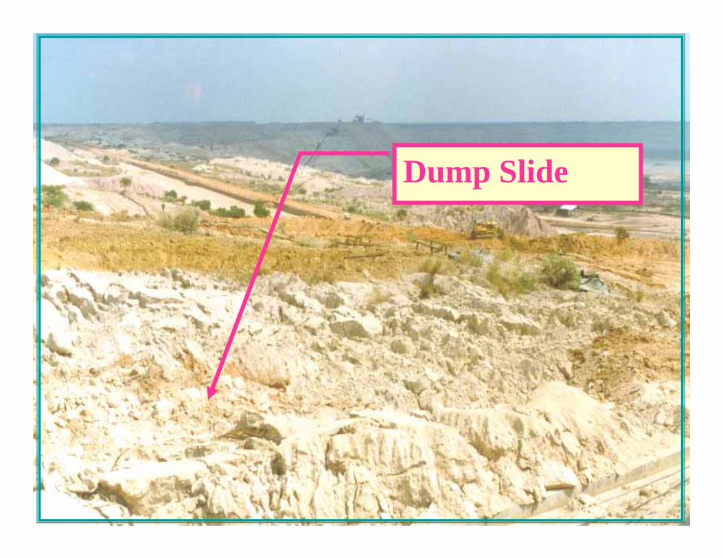
Dump Slide

Dump Slide

Dump Slide –Preventive Measure

Massive Dump Slide at the Toe

Cavity formation due to dump Slide

Dump Slide –Preventive Measure

Dump Slide

Dump Slide

Dump Slide