ni cvs-1457rt user manual - national · pdf fileni vision ni cvs-1457rt user manual gige...
TRANSCRIPT

NI VisionNI CVS-1457RT User ManualGigE Vision Compact Vision System
NI CVS-1457RT User Manual
October 2013374217A-01

Support
Worldwide Technical Support and Product Informationni.com
Worldwide Offices
Visit ni.com/niglobal to access the branch office Web sites, which provide up-to-date contact information, support phone numbers, email addresses, and current events.
National Instruments Corporate Headquarters
11500 North Mopac Expressway Austin, Texas 78759-3504 USA Tel: 512 683 0100
For further support information, refer to the Technical Support and Professional Services appendix. To comment on National Instruments documentation, refer to the National Instruments Web site at ni.com/info and enter the Info Code feedback.
© 2013 National Instruments. All rights reserved.

Important Information
WarrantyNI devices are warranted against defects in materials and workmanship for a period of one year from the invoice date, as evidenced by receipts or other documentation. National Instruments will, at its option, repair or replace equipment that proves to be defective during the warranty period. This warranty includes parts and labor.
The media on which you receive National Instruments software are warranted not to fail to execute programming instructions, due to defects in materials and workmanship, for a period of 90 days from the invoice date, as evidenced by receipts or other documentation. National Instruments will, at its option, repair or replace software media that do not execute programming instructions if National Instruments receives notice of such defects during the warranty period. National Instruments does not warrant that the operation of the software shall be uninterrupted or error free.
A Return Material Authorization (RMA) number must be obtained from the factory and clearly marked on the outside of the package before any equipment will be accepted for warranty work. National Instruments will pay the shipping costs of returning to the owner parts which are covered by warranty.
National Instruments believes that the information in this document is accurate. The document has been carefully reviewed for technical accuracy. In the event that technical or typographical errors exist, National Instruments reserves the right to make changes to subsequent editions of this document without prior notice to holders of this edition. The reader should consult National Instruments if errors are suspected. In no event shall National Instruments be liable for any damages arising out of or related to this document or the information contained in it.
EXCEPT AS SPECIFIED HEREIN, NATIONAL INSTRUMENTS MAKES NO WARRANTIES, EXPRESS OR IMPLIED, AND SPECIFICALLY DISCLAIMS ANY WARRANTY OF MERCHANTABILITY OR FITNESS FOR A PARTICULAR PURPOSE. CUSTOMER’S RIGHT TO RECOVER DAMAGES CAUSED BY FAULT OR NEGLIGENCE ON THE PART OF NATIONAL INSTRUMENTS SHALL BE LIMITED TO THE AMOUNT THERETOFORE PAID BY THE CUSTOMER. NATIONAL INSTRUMENTS WILL NOT BE LIABLE FOR DAMAGES RESULTING FROM LOSS OF DATA, PROFITS, USE OF PRODUCTS, OR INCIDENTAL OR CONSEQUENTIAL DAMAGES, EVEN IF ADVISED OF THE POSSIBILITY THEREOF. This limitation of the liability of National Instruments will apply regardless of the form of action, whether in contract or tort, including negligence. Any action against National Instruments must be brought within one year after the cause of action accrues. National Instruments shall not be liable for any delay in performance due to causes beyond its reasonable control. The warranty provided herein does not cover damages, defects, malfunctions, or service failures caused by owner’s failure to follow the National Instruments installation, operation, or maintenance instructions; owner’s modification of the product; owner’s abuse, misuse, or negligent acts; and power failure or surges, fire, flood, accident, actions of third parties, or other events outside reasonable control.
CopyrightUnder the copyright laws, this publication may not be reproduced or transmitted in any form, electronic or mechanical, including photocopying, recording, storing in an information retrieval system, or translating, in whole or in part, without the prior written consent of National Instruments Corporation.
National Instruments respects the intellectual property of others, and we ask our users to do the same. NI software is protected by copyright and other intellectual property laws. Where NI software may be used to reproduce software or other materials belonging to others, you may use NI software only to reproduce materials that you may reproduce in accordance with the terms of any applicable license or other legal restriction.
End-User License Agreements and Third-Party Legal NoticesYou can find end-user license agreements (EULAs) and third-party legal notices in the following locations:
• Notices are located in the <National Instruments>\_Legal Information and <National Instruments> directories.
• EULAs are located in the <National Instruments>\Shared\MDF\Legal\license directory.
• Review <National Instruments>\_Legal Information.txt for more information on including legal information in installers built with NI products.
TrademarksRefer to the NI Trademarks and Logo Guidelines at ni.com/trademarks for more information on National Instruments trademarks.
ARM, Keil, and µVision are trademarks or registered of ARM Ltd or its subsidiaries.
LEGO, the LEGO logo, WEDO, and MINDSTORMS are trademarks of the LEGO Group. ©2013 The LEGO Group.
TETRIX by Pitsco is a trademark of Pitsco, Inc.©2013
FIELDBUS FOUNDATION™ and FOUNDATION™ are trademarks of the Fieldbus Foundation.
EtherCAT® is a registered trademark of and licensed by Beckhoff Automation GmbH.
CANopen® is a registered Community Trademark of CAN in Automation e.V.
DeviceNet™ and EtherNet/IP™ are trademarks of ODVA.
Go!, SensorDAQ, and Vernier are registered trademarks of Vernier Software & Technology. Vernier Software & Technology and vernier.com are trademarks or trade dress.
Xilinx is the registered trademark of Xilinx, Inc.
Taptite and Trilobular are registered trademarks of Research Engineering & Manufacturing Inc.
FireWire® is the registered trademark of Apple Inc.
Linux® is the registered trademark of Linus Torvalds in the U.S. and other countries.

Handle Graphics®, MATLAB®, Real-Time Workshop®, Simulink®, Stateflow®, and xPC TargetBox® are registered trademarks, and TargetBox™ and Target Language Compiler™ are trademarks of The MathWorks, Inc.
Tektronix®, Tek, and Tektronix, Enabling Technology are registered trademarks of Tektronix, Inc.
The Bluetooth® word mark is a registered trademark owned by the Bluetooth SIG, Inc.
The ExpressCard™ word mark and logos are owned by PCMCIA and any use of such marks by National Instruments is under license.
The mark LabWindows is used under a license from Microsoft Corporation. Windows is a registered trademark of Microsoft Corporation in the United States and other countries.
Other product and company names mentioned herein are trademarks or trade names of their respective companies.
Members of the National Instruments Alliance Partner Program are business entities independent from National Instruments and have no agency, partnership, or joint-venture relationship with National Instruments.
PatentsFor patents covering National Instruments products/technology, refer to the appropriate location: Help»Patents in your software, the patents.txt file on your media, or the National Instruments Patent Notice at ni.com/patents.
Export Compliance InformationRefer to the Export Compliance Information at ni.com/legal/export-compliance for the National Instruments global trade compliance policy and how to obtain relevant HTS codes, ECCNs, and other import/export data.
WARNING REGARDING USE OF NATIONAL INSTRUMENTS PRODUCTS(1) NATIONAL INSTRUMENTS PRODUCTS ARE NOT DESIGNED WITH COMPONENTS AND TESTING FOR A LEVEL OF RELIABILITY SUITABLE FOR USE IN OR IN CONNECTION WITH SURGICAL IMPLANTS OR AS CRITICAL COMPONENTS IN ANY LIFE SUPPORT SYSTEMS WHOSE FAILURE TO PERFORM CAN REASONABLY BE EXPECTED TO CAUSE SIGNIFICANT INJURY TO A HUMAN.
(2) IN ANY APPLICATION, INCLUDING THE ABOVE, RELIABILITY OF OPERATION OF THE SOFTWARE PRODUCTS CAN BE IMPAIRED BY ADVERSE FACTORS, INCLUDING BUT NOT LIMITED TO FLUCTUATIONS IN ELECTRICAL POWER SUPPLY, COMPUTER HARDWARE MALFUNCTIONS, COMPUTER OPERATING SYSTEM SOFTWARE FITNESS, FITNESS OF COMPILERS AND DEVELOPMENT SOFTWARE USED TO DEVELOP AN APPLICATION, INSTALLATION ERRORS, SOFTWARE AND HARDWARE COMPATIBILITY PROBLEMS, MALFUNCTIONS OR FAILURES OF ELECTRONIC MONITORING OR CONTROL DEVICES, TRANSIENT FAILURES OF ELECTRONIC SYSTEMS (HARDWARE AND/OR SOFTWARE), UNANTICIPATED USES OR MISUSES, OR ERRORS ON THE PART OF THE USER OR APPLICATIONS DESIGNER (ADVERSE FACTORS SUCH AS THESE ARE HEREAFTER COLLECTIVELY TERMED “SYSTEM FAILURES”). ANY APPLICATION WHERE A SYSTEM FAILURE WOULD CREATE A RISK OF HARM TO PROPERTY OR PERSONS (INCLUDING THE RISK OF BODILY INJURY AND DEATH) SHOULD NOT BE RELIANT SOLELY UPON ONE FORM OF ELECTRONIC SYSTEM DUE TO THE RISK OF SYSTEM FAILURE. TO AVOID DAMAGE, INJURY, OR DEATH, THE USER OR APPLICATION DESIGNER MUST TAKE REASONABLY PRUDENT STEPS TO PROTECT AGAINST SYSTEM FAILURES, INCLUDING BUT NOT LIMITED TO BACK-UP OR SHUT DOWN MECHANISMS. BECAUSE EACH END-USER SYSTEM IS CUSTOMIZED AND DIFFERS FROM NATIONAL INSTRUMENTS' TESTING PLATFORMS AND BECAUSE A USER OR APPLICATION DESIGNER MAY USE NATIONAL INSTRUMENTS PRODUCTS IN COMBINATION WITH OTHER PRODUCTS IN A MANNER NOT EVALUATED OR CONTEMPLATED BY NATIONAL INSTRUMENTS, THE USER OR APPLICATION DESIGNER IS ULTIMATELY RESPONSIBLE FOR VERIFYING AND VALIDATING THE SUITABILITY OF NATIONAL INSTRUMENTS PRODUCTS WHENEVER NATIONAL INSTRUMENTS PRODUCTS ARE INCORPORATED IN A SYSTEM OR APPLICATION, INCLUDING, WITHOUT LIMITATION, THE APPROPRIATE DESIGN, PROCESS AND SAFETY LEVEL OF SUCH SYSTEM OR APPLICATION.

Compliance
Electromagnetic Compatibility InformationThis hardware has been tested and found to comply with the applicable regulatory requirements and limits for electromagnetic compatibility (EMC) as indicated in the hardware’s Declaration of Conformity (DoC)1. These requirements and limits are designed to provide reasonable protection against harmful interference when the hardware is operated in the intended electromagnetic environment. In special cases, for example when either highly sensitive or noisy hardware is being used in close proximity, additional mitigation measures may have to be employed to minimize the potential for electromagnetic interference.
While this hardware is compliant with the applicable regulatory EMC requirements, there is no guarantee that interference will not occur in a particular installation. To minimize the potential for the hardware to cause interference to radio and television reception or to experience unacceptable performance degradation, install and use this hardware in strict accordance with the instructions in the hardware documentation and the DoC1.
If this hardware does cause interference with licensed radio communications services or other nearby electronics, which can be determined by turning the hardware off and on, you are encouraged to try to correct the interference by one or more of the following measures:• Reorient the antenna of the receiver (the device suffering interference).• Relocate the transmitter (the device generating interference) with respect to the receiver.• Plug the transmitter into a different outlet so that the transmitter and the receiver are on different branch
circuits.
Some hardware may require the use of a metal, shielded enclosure (windowless version) to meet the EMC requirements for special EMC environments such as, for marine use or in heavy industrial areas. Refer to the hardware’s user documentation and the DoC1 for product installation requirements.
When the hardware is connected to a test object or to test leads, the system may become more sensitive to disturbances or may cause interference in the local electromagnetic environment.
Operation of this hardware in a residential area is likely to cause harmful interference. Users are required to correct the interference at their own expense or cease operation of the hardware.
Changes or modifications not expressly approved by National Instruments could void the user’s right to operate the hardware under the local regulatory rules.
1 The Declaration of Conformity (DoC) contains important EMC compliance information and instructions for the user or installer. To obtain the DoC for this product, visit ni.com/certification, search by model number or product line, and click the appropriate link in the Certification column.
© National Instruments | vii
Contents
About This ManualConventions ...................................................................................................................... ixRelated Documentation .................................................................................................... ix
Chapter 1NI CVS-1457RT OverviewAbout the NI CVS-1457RT.............................................................................................. 1-1Hardware Overview.......................................................................................................... 1-1Software Overview ........................................................................................................... 1-2
NI Vision Builder for Automated Inspection ........................................................... 1-3LabVIEW.................................................................................................................. 1-3
LabVIEW Real-Time Module .......................................................................... 1-3LabVIEW FPGA Module................................................................................. 1-3NI Vision Development Module ...................................................................... 1-3NI Vision Acquisition Software ....................................................................... 1-4
GigE Vision Interface Overview ...................................................................................... 1-5
Chapter 2LEDs, RESET Button, and ConnectorsLED Indicators ................................................................................................................. 2-1
STATUS LED .......................................................................................................... 2-2PWR/FAULT LED................................................................................................... 2-3USER1/USER2 LEDs .............................................................................................. 2-3PoE LEDs ................................................................................................................. 2-4Ethernet LEDs .......................................................................................................... 2-4
Using the RESET Button.................................................................................................. 2-6Safe Mode................................................................................................................. 2-7IP Reset..................................................................................................................... 2-7No App ..................................................................................................................... 2-8
Connectors ........................................................................................................................ 2-8Earth Ground Connection......................................................................................... 2-9Power Input Connectors ........................................................................................... 2-10Primary Ethernet Port ............................................................................................... 2-11USB Connectors ....................................................................................................... 2-12RS-485/422/232 Serial Port...................................................................................... 2-12
VGA Port .......................................................................................................... 2-14GigE Vision Ports with PoE ..................................................................................... 2-15Digital I/O................................................................................................................. 2-15
Contents
viii | ni.com
Chapter 3DeploymentConnecting Multiple NI CVS-1457RT Devices ...............................................................3-1
Chapter 4BIOS Configuration and System RecoveryEntering BIOS Setup ........................................................................................................4-1
Main Menu................................................................................................................4-2Advanced Menu........................................................................................................4-2
CPU Configuration Submenu ...........................................................................4-2Power/Wake Configuration Submenu ..............................................................4-3USB Configuration Submenu ...........................................................................4-3Serial Port Configuration Submenu..................................................................4-4
LabVIEW RT Menu .................................................................................................4-4Boot Menu ................................................................................................................4-5
Hard Drive BBS Priorities Submenu ................................................................4-6CD/DVD ROM Drive BBS Priorities Submenu...............................................4-6Floppy Drive BBS Priorities Submenu.............................................................4-6Network Device BBS Priorities Submenu........................................................4-6
Security Menu...........................................................................................................4-7Save & Exit Menu.....................................................................................................4-7
Restoring the NI CVS-1457RT to Factory Default Condition .........................................4-8
Appendix ATroubleshootingSoftware Configuration Problems ....................................................................................A-1
The NI CVS-1457RT Does Not Appear in MAX or in Vision Builder AI ..............A-1No Software is Installed............................................................................................A-2No Camera Found.....................................................................................................A-2
Hardware Problems...........................................................................................................A-3PWR/FAULT LED is Red........................................................................................A-3Cannot Drive Isolated Outputs .................................................................................A-3Runaway Startup Application...................................................................................A-3LED Error Indications ..............................................................................................A-3PWR/FAULT LED Is Not Lit When the NI CVS-1457RT is Powered On .............A-3
Appendix BMounting InformationMounting the NI CVS-1457RT ........................................................................................B-1
Clearance Requirements ...........................................................................................B-6
Appendix CTechnical Support and Professional Services
© National Instruments | ix
About This Manual
This manual contains detailed electrical and mechanical information for the National Instruments CVS-1457RT.
ConventionsThe following conventions appear in this manual:
This icon denotes a note, which alerts you to important information.
This icon denotes a caution, which advises you of precautions to take to avoid injury, data loss, or a system crash.
When this symbol is marked on a product, it denotes a warning advising you to take precautions to avoid electrical shock.
bold Bold text denotes items that you must select or click in the software, such as menu items and dialog box options. Bold text also denotes parameter names.
italic Italic text denotes variables, emphasis, a cross-reference, or an introduction to a key concept. Italic text also denotes text that is a placeholder for a word or value that you must supply.
monospace Text in this font denotes text or characters that you should enter from the keyboard, sections of code, programming examples, and syntax examples. This font is also used for the proper names of disk drives, paths, directories, programs, subprograms, subroutines, device names, functions, operations, variables, filenames, and extensions.
monospace Italic text in this font denotes text that is a placeholder for a word oritalic value that you must supply.
Related DocumentationThe following documents contain information that you may find helpful as you read this manual:
• NI CVS-1457RT Specifications—Contains detailed specifications for the NI CVS-1457RT.
• NI CVS-1457RT Getting Started Guide—Explains how to install and configure the software necessary to use the NI CVS-1457RT, and how to get started using the NI CVS-1457RT hardware.
• NI CVS I/O Accessory User Manual—Contains installation and operation instructions for the CVS I/O Accessory.
About This Manual
x | ni.com
Resources for NI Vision Builder AI UsersRefer to the NI Vision Builder for Automated Inspection Tutorial to learn how to perform basic machine vision techniques using Vision Builder AI. You can access the NI Vision Builder for Automated Inspection Tutorial and other documentation by selecting Start»All Programs»National Instruments»Vision Builder AI»Documentation. You can also access context help within Vision Builder AI by clicking the Show Context Help button on the Vision Builder AI toolbar.
Examples of common Vision Builder AI inspections are installed to the <Vision Builder AI>\Examples directory, where <Vision Builder AI> is the location Vision Builder AI is installed.
NI Vision Builder for Automated Inspection: Configuration Help—Contains information about using the Vision Builder for Automated Inspection Configuration Interface to create a machine vision application.
NI Vision Builder for Automated Inspection: Inspection Help—Contains information about running applications created with Vision Builder for Automated Inspection in the Vision Builder Automated Inspection Interface.
Resources for NI LabVIEW, NI Vision Development Module, and NI Vision Acquisition Software UsersDocumentation for LabVIEW, the LabVIEW Real-Time Module, and the LabVIEW FPGA Module is available from the Help menu on the LabVIEW toolbar. You can access documentation for the NI Vision Development Module by selecting Start»All Programs»National Instruments»Vision»Documentation»NI Vision.
Documentation for the NI-IMAQdx driver software is available by selecting Start»All Programs»National Instruments»Vision»Documentation»NI-IMAQdx.
Documentation for the NI-IMAQ I/O driver software is available by selecting Start»All Programs»National Instruments»Vision»Documentation»NI-IMAQ IO.
Documentation for the MAX configuration software is available from the Help menu on the MAX toolbar. Specific information about using MAX with NI Vision hardware is available by selecting Help»Help Topics»NI Vision»NI-IMAQdx.
National Instruments Example Finder—LabVIEW contains an extensive library of VIs and example programs. To access the NI Example Finder, open LabVIEW and select Help»Find Examples.
Visit the NI Developer Zone at ni.com/zone for the latest example programs, tutorials, technical presentations, and a community area where you can share ideas, questions, and source code with developers around the world.
© National Instruments | 1-1
1NI CVS-1457RT Overview
This chapter provides an overview of the features and components of the National Instruments CVS-1457RT compact vision system.
About the NI CVS-1457RTThe NI CVS-1457RT is a real-time imaging system that acquires, processes, and displays images from GigE Vision cameras. The NI CVS-1457RT also provides multiple digital input/output (I/O) options for communicating with external devices to configure and start an inspection and to indicate results.
An Ethernet connection between the NI CVS-1457RT and a development computer allows you to display measurement results and status information and to configure the NI CVS-1457RT settings. When configured, the NI CVS-1457RT can run applications without a connection to the development computer.
Hardware OverviewThe NI CVS-1457RT front panel consists of a VGA connector, RJ50 serial port, two USB 2.0 ports, a 10/100/1000 Ethernet connector, and two Power over Ethernet (PoE) enabled GigE Vision ports.
The NI CVS-1457RT front panel also includes LEDs for communicating system status and a 44-pin digital I/O port. The digital I/O port offers 8 isolated inputs, 8 isolated outputs, 2 bidirectional differential pairs (RS-422) or single-ended input lines that can be used with a quadrature encoder, and 8 bidirectional TTL lines.
1-2 | ni.com
Chapter 1 NI CVS-1457RT Overview
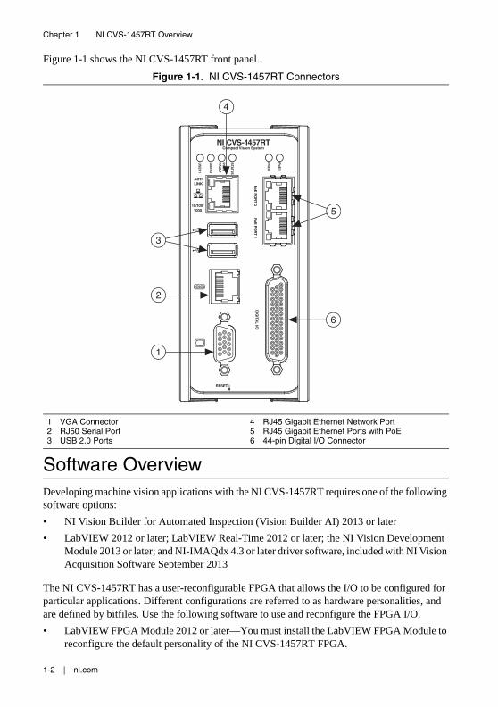
Figure 1-1 shows the NI CVS-1457RT front panel.
Figure 1-1. NI CVS-1457RT Connectors
Software OverviewDeveloping machine vision applications with the NI CVS-1457RT requires one of the following software options:
• NI Vision Builder for Automated Inspection (Vision Builder AI) 2013 or later
• LabVIEW 2012 or later; LabVIEW Real-Time 2012 or later; the NI Vision Development Module 2013 or later; and NI-IMAQdx 4.3 or later driver software, included with NI Vision Acquisition Software September 2013
The NI CVS-1457RT has a user-reconfigurable FPGA that allows the I/O to be configured for particular applications. Different configurations are referred to as hardware personalities, and are defined by bitfiles. Use the following software to use and reconfigure the FPGA I/O.
• LabVIEW FPGA Module 2012 or later—You must install the LabVIEW FPGA Module to reconfigure the default personality of the NI CVS-1457RT FPGA.
1 VGA Connector2 RJ50 Serial Port3 USB 2.0 Ports
4 RJ45 Gigabit Ethernet Network Port5 RJ45 Gigabit Ethernet Ports with PoE6 44-pin Digital I/O Connector
NI CVS-1457RTCompact Vision System
RESET
DIG
ITAL I/O
10/100/1000
ACT/LINK
US
ER
1
US
ER
2
PW
R/
FAU
LT
STA
TUS
PoE
0
PoE
PO
RT 0
PoE
PO
RT 1
PoE
1
5
3
6
1
4
2
© National Instruments | 1-3
NI CVS-1457RT User Manual
• NI-IMAQ I/O 2.8 or later driver software, included with NI Vision Acquisition Software September 2013—NI-IMAQ I/O is required to use the default personality of the NI CVS-1457RT in LabVIEW, or to reconfigure the default personality of the NI CVS-1457RT I/O in the LabVIEW FPGA Module.
The installation and configuration process for each development environment is different. Refer to the NI CVS-1457RT Getting Started Guide for installation and configuration instructions.
The following sections describe the software options. For detailed information about individual software packages, refer to the documentation specific to the software.
NI Vision Builder for Automated InspectionVision Builder AI is configurable machine vision software that you can use to prototype, benchmark, and deploy machine vision applications. Creating applications in Vision Builder AI does not require programming. It also allows you to easily configure and benchmark a sequence of visual inspection steps, as well as deploy the visual inspection system for automated inspection. With Vision Builder AI, you can perform powerful visual inspection tasks and make decisions based on the results of individual tasks. You can also migrate your configured inspection to LabVIEW, extending the capabilities of your applications if necessary. Vision Builder AI allows you to remotely configure and control the NI CVS-1457RT.
LabVIEWLabVIEW is a graphical programming environment for developing flexible and scalable applications.
LabVIEW Real-Time ModuleThe LabVIEW Real-Time Module combines LabVIEW graphical programming with the power of real-time (RT) hardware, such as the NI CVS-1457RT, enabling you to build deterministic, real-time systems. You develop VIs in LabVIEW and embed the VIs on RT targets. The RT target runs VIs without a user interface and offers a stable platform for real-time VIs. For more information about the LabVIEW Real-Time Module, refer to the LabVIEW Help.
LabVIEW FPGA ModuleThe LabVIEW FPGA Module extends the LabVIEW graphical development platform to target field-programmable gate arrays (FPGAs) on NI reconfigurable I/O (RIO) hardware. LabVIEW FPGA enables developers to more efficiently and effectively design complex systems by providing a highly integrated development environment, a large ecosystem of IP libraries, a high fidelity simulator, and debugging features.
NI Vision Development ModuleThe NI Vision Development Module is an image processing and analysis library of hundreds or functions for the following common machine vision tasks:
• Pattern matching
1-4 | ni.com
Chapter 1 NI CVS-1457RT Overview
• Particle analysis
• Gauging
• Taking measurements
• Grayscale, color, and binary image display
With the NI Vision Development Module you can acquire, display, and store images as well as perform image analysis and processing. Using the NI Vision Development Module, imaging novices and experts can program the most basic or complicated image applications without knowledge of particular algorithm implementations.
NI Vision Assistant, which is included with the NI Vision Development Module, is an interactive prototyping tool for machine vision and scientific imaging developers. With Vision Assistant, you can prototype vision applications quickly and test how various vision image processing functions work. Using the Vision Assistant LabVIEW VI creation wizard, you can create LabVIEW VI block diagrams that perform the prototype you created in Vision Assistant. You can use them in LabVIEW to add functionality to the generated VI.
For information about how to use the NI Vision Development Module with LabVIEW, refer to the NI Vision for LabVIEW Help.
NI Vision Acquisition SoftwareThe NI CVS-1457RT ships with the latest version of NI Vision Acquisition Software, which contains all of the drivers in the NI Vision product line. With NI Vision Acquisition Software, you can quickly and easily start your applications without having to program the device at the register level.
NI Vision Acquisition Software has an extensive library of functions—such as routines for video configuration, continuous and single shot image acquisition, memory buffer allocation, trigger control, and device configuration—that you can call from the application development environment.
NI Vision Acquisition Software contains the following software for use with the NI CVS-1457RT:
• Measurement & Automation Explorer (MAX)—Use MAX to configure the NI CVS-1457RT. You can set the IP address, update software on the device, configure triggering, and set up the lighting features.
• NI-IMAQdx—Controls GigE Vision cameras connected to the NI CVS-1457RT. NI-IMAQdx includes an extensive library of VIs you can call from LabVIEW. These VIs include routines for video configuration, continuous and single-shot image acquisition, trigger control, and register-level camera configuration. NI-IMAQdx software performs all functions necessary for acquiring and saving images.
• NI-IMAQ I/O—Controls the I/O on the NI CVS-1457RT.
© National Instruments | 1-5
NI CVS-1457RT User Manual
GigE Vision Interface OverviewGigE Vision is a camera interface standard based on the Gigabit Ethernet communication protocol. GigE Vision cameras work with standard Gigabit Ethernet networks and hardware. Because the Gigabit Ethernet standard allows transmission of up to 1000 megabits per second, GigE Vision offers faster transmission rates than USB 1.x, USB 2.0, IEEE 1394a and IEEE 1394b. GigE Vision networks can acquire images from multiple cameras; however, all cameras on the network share the same bandwidth.
While Gigabit Ethernet is a standard bus technology, not all cameras with Gigabit Ethernet ports are GigE Vision compliant. In order to be GigE Vision Compliant, the camera must adhere to the protocols laid down by the GigE Vision standard and must be certified by the Automated Imaging Association (AIA). Look for the GigE Vision logo in the camera documentation to determine if the camera supports the GigE Vision standard.
© National Instruments | 2-1
2LEDs, RESET Button, and Connectors
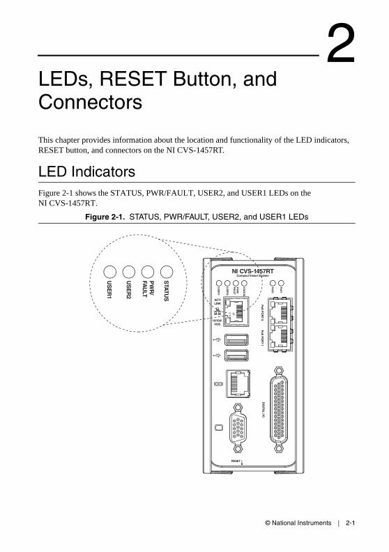
This chapter provides information about the location and functionality of the LED indicators, RESET button, and connectors on the NI CVS-1457RT.
LED IndicatorsFigure 2-1 shows the STATUS, PWR/FAULT, USER2, and USER1 LEDs on the NI CVS-1457RT.
Figure 2-1. STATUS, PWR/FAULT, USER2, and USER1 LEDs
NI CVS-1457RTCompact Vision System
RESET
DIG
ITAL I/O
10/100/1000
ACT/LINK
US
ER
1
US
ER
2
PW
R/
FAU
LT
STA
TUS
PoE
0
PoE
PO
RT 0
PoE
PO
RT 1
PoE
1
US
ER
1
US
ER
2
PW
R/
FAU
LT
STA
TUS

2-2 | ni.com
Chapter 2 LEDs, RESET Button, and Connectors
STATUS LEDThe following table describes the STATUS LED indications.
Table 2-1. STATUS LED Indications
STATUS LED (Amber) State NI CVS-1457RT State
OFF The NI CVS-1457RT initialized successfully and is ready for use.
1 blink The NI CVS-1457RT IP address or software is unconfigured. The device ships from the factory unconfigured. The NI CVS-1457RT also enters the unconfigured state if it is configured for DHCP and no DHCP server is available. Use MAX or Vision Builder AI to configure the device.
2 blinks The NI CVS-1457RT detects an error in the software configuration. The device has automatically started up into safe mode. This usually occurs when an attempt to upgrade the software is interrupted or if system files are deleted from the NI CVS-1457RT. Reinstall software on the NI CVS-1457RT. Refer to the NI CVS-1457RT Getting Started Guide for information about installing software on the NI CVS-1457RT.
3 blinks The NI CVS-1457RT has booted into safe mode. Refer to the Safe Mode section for information about the safe mode state.
4 blinks The NI CVS-1457RT has experienced two consecutive software exceptions. The NI CVS-1457RT automatically restarts after an exception. After the second exception, the NI CVS-1457RT remains in the exception state, alerting you to resolve the problem. Reinstall software on the NI CVS-1457RT or contact National Instruments for assistance. Refer to the NI CVS-1457RT Getting Started Guide for information about installing software on the NI CVS-1457RT.
Continuous blink The NI CVS-1457RT detects a software crash or hang. Contact National Instruments for assistance.
ON When the BIOS Boot Configuration is set to LabVIEW RT, this LED is ON during LabVIEW Real-Time initialization. If the LED remains ON after the expected LabVIEW Real-Time initialization, the NI CVS-1457RT detects a critical hardware error. Contact National Instruments for assistance.
When the BIOS Boot Configuration is set to Windows/Other, this LED remains ON after initialization.
© National Instruments | 2-3
NI CVS-1457RT User Manual
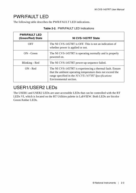
PWR/FAULT LEDThe following table describes the PWR/FAULT LED indications.
USER1/USER2 LEDsThe USER1 and USER2 LEDs are user-accessible LEDs that can be controlled with the RT LEDs VI, which is located on the RT Utilities palette in LabVIEW. Both LEDs are bicolor Green/Amber LEDs.
Table 2-2. PWR/FAULT LED Indications
PWR/FAULT LED (Green/Red) State NI CVS-1457RT State
OFF The NI CVS-1457RT is OFF. This is not an indication of whether power is applied or not.
ON - Green The NI CVS-1457RT is operating normally and is properly powered on.
Blinking - Red The NI CVS-1457RT power-up sequence failed.
ON - Red The NI CVS-1457RT is experiencing a thermal fault. Ensure that the ambient operating temperature does not exceed the range specified in the NI CVS-1457RT Specifications Environmental section.
2-4 | ni.com
Chapter 2 LEDs, RESET Button, and Connectors
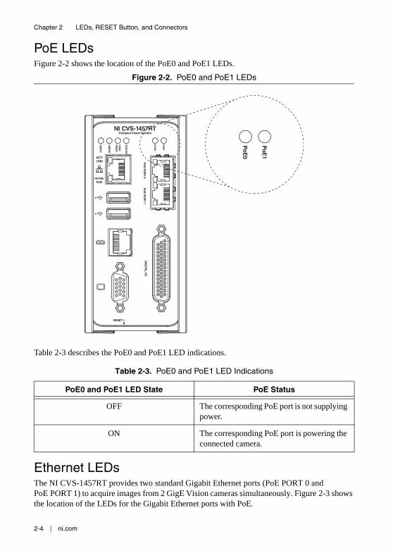
PoE LEDsFigure 2-2 shows the location of the PoE0 and PoE1 LEDs.
Figure 2-2. PoE0 and PoE1 LEDs
Table 2-3 describes the PoE0 and PoE1 LED indications.
Ethernet LEDsThe NI CVS-1457RT provides two standard Gigabit Ethernet ports (PoE PORT 0 and PoE PORT 1) to acquire images from 2 GigE Vision cameras simultaneously. Figure 2-3 shows the location of the LEDs for the Gigabit Ethernet ports with PoE.
Table 2-3. PoE0 and PoE1 LED Indications
PoE0 and PoE1 LED State PoE Status
OFF The corresponding PoE port is not supplying power.
ON The corresponding PoE port is powering the connected camera.
NI CVS-1457RTCompact Vision System
RESET
DIG
ITAL I/O
10/100/1000
ACT/LINK
US
ER
1
US
ER
2
PW
R/
FAU
LT
STA
TUS
PoE
0
PoE
PO
RT 0
PoE
PO
RT 1
PoE
1
PoE
0
PoE
1

© National Instruments | 2-5
NI CVS-1457RT User Manual
Figure 2-3. LEDs for the Gigabit Ethernet Ports with PoE
Figure 2-4 shows the LEDs for the primary Gigabit Ethernet network port. The primary network port provides a connection between the NI CVS-1457RT and the development computer.
Figure 2-4. LEDS for the Primary Gigabit Ethernet Network Port
Refer to Table 2-4 for information on the Ethernet LED indications.
1 Port 0 Speed LED2 Port 0 Activity/Link LED
3 Port 1 Speed LED4 Port 1 Activity/Link LED
1 Activity/Link LED 2 Speed LED
Table 2-4. Ethernet LED Indications
LED Status Definition
Activity/Link
Unlit No link has been established
Solid A link has been negotiated
Blinking Activity on the link
Speed
Unlit No link, or 10 Mbps link
Green 100 Mbps link
Amber 1,000 Mbps link
1
2
3
4
PoE
PO
RT 0
PoE
PO
RT 1
1
2
2-6 | ni.com
Chapter 2 LEDs, RESET Button, and Connectors
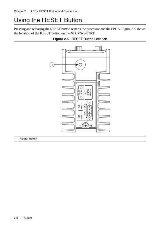
Using the RESET ButtonPressing and releasing the RESET button restarts the processor and the FPGA. Figure 2-5 shows the location of the RESET button on the NI CVS-1457RT.
Figure 2-5. RESET Button Location
1 RESET Button
SY
STE
M
PoE
48 V
ISO C
ISO
CPo
EV P
oEV I
SO
5-24
V
12-2
4 V
C
V
1
© National Instruments | 2-7
NI CVS-1457RT User Manual
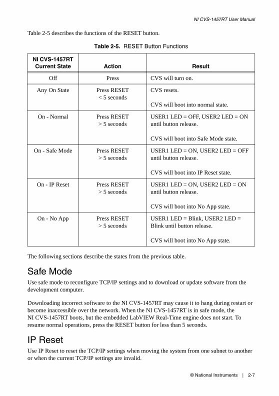
Table 2-5 describes the functions of the RESET button.
The following sections describe the states from the previous table.
Safe ModeUse safe mode to reconfigure TCP/IP settings and to download or update software from the development computer.
Downloading incorrect software to the NI CVS-1457RT may cause it to hang during restart or become inaccessible over the network. When the NI CVS-1457RT is in safe mode, the NI CVS-1457RT boots, but the embedded LabVIEW Real-Time engine does not start. To resume normal operations, press the RESET button for less than 5 seconds.
IP ResetUse IP Reset to reset the TCP/IP settings when moving the system from one subnet to another or when the current TCP/IP settings are invalid.
Table 2-5. RESET Button Functions
NI CVS-1457RT Current State Action Result
Off Press CVS will turn on.
Any On State Press RESET < 5 seconds
CVS resets.
CVS will boot into normal state.
On - Normal Press RESET > 5 seconds
USER1 LED = OFF, USER2 LED = ON until button release.
CVS will boot into Safe Mode state.
On - Safe Mode Press RESET > 5 seconds
USER1 LED = ON, USER2 LED = OFF until button release.
CVS will boot into IP Reset state.
On - IP Reset Press RESET > 5 seconds
USER1 LED = ON, USER2 LED = ON until button release.
CVS will boot into No App state.
On - No App Press RESET > 5 seconds
USER1 LED = Blink, USER2 LED = Blink until button release.
CVS will boot into No App state.

2-8 | ni.com
Chapter 2 LEDs, RESET Button, and Connectors
When the NI CVS-1457RT is in the IP Reset state, the IP address of the network port resets to DHCP or a link-local address. You can then set up a new network configuration for the NI CVS-1457RT from a development machine on the same subnet, or you can connect the NI CVS-1457RT directly to the development computer.
Note By default, the target automatically attempts to connect to the network using DHCP. If the target is unable to initiate a DHCP connection, the target connects to the network with a link-local IP address (169.254.x.x).
No AppTo prevent the NI CVS-1457RT from automatically running VIs at startup, put the NI CVS-1457RT into the No App state. If the NI CVS-1457RT becomes inaccessible because of a startup program, enable the No App state and reconfigure the NI CVS-1457RT.
ConnectorsThis section describes the connectors on the NI CVS-1457RT and includes pinouts and signal descriptions for each connector.
Table 2-6 summarizes the functions of the connectors and features on the NI CVS-1457RT.
Table 2-6. Connector Overview
Connector Function
External earth ground lug Connects chassis to earth ground
2-position SYSTEM power connector System power
2-position PoE power connector Power to PoE-enabled cameras
2-position ISO power connector Power to isolated outputs
RJ45 10/100/1000 Ethernet port Primary Ethernet network connection
USB 4-pin Series A receptacles High-retention USB 2.0
RJ50 serial port RS-485/422/232 serial
15-pin female VGA Video output
PoE PORT 0 and PoE PORT 1 Power and data connection to GigE Vision cameras
44-pin female DIGITAL I/O Isolated inputs, isolated outputs, bidirectional differential lines (RS-422) or single-ended lines which can be used with a quadrature encoder, and bidirectional TTL lines

© National Instruments | 2-9
NI CVS-1457RT User Manual
Earth Ground ConnectionUse the grounding lug on the NI CVS-1457RT, shown in Figure 2-6, to connect the chassis to earth ground.
Note An earth ground connection does not connect C, CISO, or CPoE to earth ground.
Figure 2-6. External Ground Location
1 External Ground Lug
SY
STE
M
PoE
48 V
ISO C
ISO
CPo
EV P
oEV I
SO
5-24
V
12-2
4 V
C
V
1

2-10 | ni.com
Chapter 2 LEDs, RESET Button, and Connectors
Power Input ConnectorsThe NI CVS-1457RT uses three power supplies: one to power the system, one to supply power for PoE, and one to power the isolated outputs. Figure 2-7 shows the power connectors.
Figure 2-7. Power Connectors
Table 2-7 describes the terminals on the power connectors.
1 System Power Connector2 PoE Power Connector
2 ISO Power Connector
Table 2-7. Power Connector Terminals
Terminal Description
C Common signal
V System power (12-24 VDC)
CISO Isolated common signal
VISO Power for isolated outputs (5-24 VDC)
CPoE PoE common signal
VPoE PoE power (48 VDC)
SY
STE
M
PoE
48 V
ISO C
ISO
CPo
EV P
oEV I
SO
5-24
V
12-2
4 V
C
V1
3
2
© National Instruments | 2-11
NI CVS-1457RT User Manual
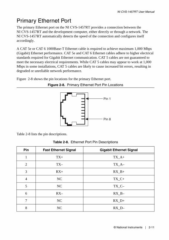
Primary Ethernet PortThe primary Ethernet port on the NI CVS-1457RT provides a connection between the NI CVS-1457RT and the development computer, either directly or through a network. The NI CVS-1457RT automatically detects the speed of the connection and configures itself accordingly.
A CAT 5e or CAT 6 1000Base-T Ethernet cable is required to achieve maximum 1,000 Mbps (Gigabit) Ethernet performance. CAT 5e and CAT 6 Ethernet cables adhere to higher electrical standards required for Gigabit Ethernet communication. CAT 5 cables are not guaranteed to meet the necessary electrical requirements. While CAT 5 cables may appear to work at 1,000 Mbps in some installations, CAT 5 cables are likely to cause increased bit errors, resulting in degraded or unreliable network performance.
Figure 2-8 shows the pin locations for the primary Ethernet port.
Figure 2-8. Primary Ethernet Port Pin Locations
Table 2-8 lists the pin descriptions.
Table 2-8. Ethernet Port Pin Descriptions
Pin Fast Ethernet Signal Gigabit Ethernet Signal
1 TX+ TX_A+
2 TX– TX_A–
3 RX+ RX_B+
4 NC TX_C+
5 NC TX_C–
6 RX– RX_B–
7 NC RX_D+
8 NC RX_D–
Pin 8
Pin 1

2-12 | ni.com
Chapter 2 LEDs, RESET Button, and Connectors
USB ConnectorsThe NI CVS-1457RT has two high-retention USB 2.0 ports. Figure 2-9 shows the pinout for the USB connectors.
Figure 2-9. USB 2.0 Connector Pinout
Table 2-9 lists and describes the USB connector signals.
RS-485/422/232 Serial PortThe NI CVS-1457RT has an RS-485/422/232 serial port used for connecting to serial devices, such as PLCs, scanners, and lighting devices. The serial port is a 10-position RJ50 modular jack. Refer to Figure 2-10 for the pin locations.
Figure 2-10. RS-485/422/232 Serial Port Pin Locations
Table 2-9. USB Connector Signals
Pin Signal Name Signal Description
1 VCC Cable Power (+5 VDC)
2 D- USB Data -
3 D+ USB Data +
4 GND Ground
4 1
Pin 10
Pin 1
© National Instruments | 2-13
NI CVS-1457RT User Manual
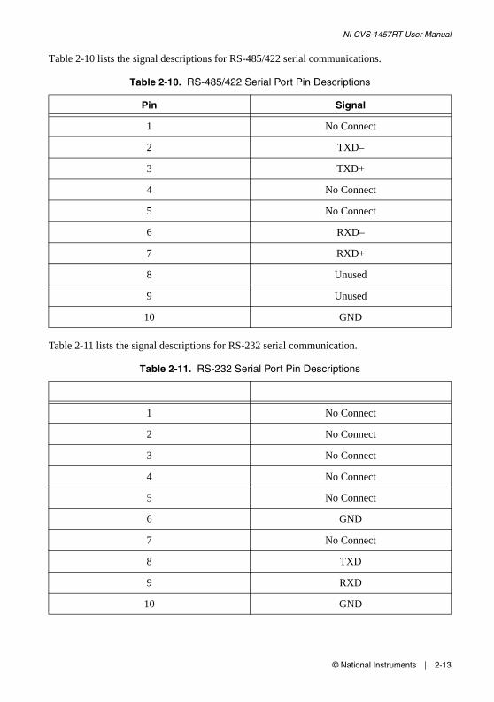
Table 2-10 lists the signal descriptions for RS-485/422 serial communications.
Table 2-11 lists the signal descriptions for RS-232 serial communication.
Table 2-10. RS-485/422 Serial Port Pin Descriptions
Pin Signal
1 No Connect
2 TXD–
3 TXD+
4 No Connect
5 No Connect
6 RXD–
7 RXD+
8 Unused
9 Unused
10 GND
Table 2-11. RS-232 Serial Port Pin Descriptions
1 No Connect
2 No Connect
3 No Connect
4 No Connect
5 No Connect
6 GND
7 No Connect
8 TXD
9 RXD
10 GND

2-14 | ni.com
Chapter 2 LEDs, RESET Button, and Connectors
VGA PortThe VGA port on the NI CVS-1457RT provides connection between the NI CVS-1457RT and a VGA monitor. Use any standard 15-pin VGA cable to access the VGA port. Figure 2-11 shows the VGA port pin locations.
Figure 2-11. VGA Port Pin Locations
The following table lists the VGA signals.
Table 2-12. VGA Port Pin Descriptions
Pin Signal Name Signal Description
1 RED Red analog video signal
2 GREEN Green analog video signal
3 BLUE Blue analog video signal
4 RESERVED Reserved
5 GND Ground reference
6 RED RETURN Ground reference
7 GREEN RETURN Ground reference
8 BLUE RETURN Ground reference
9 PWR 5 V power for DDC
10 GND Ground return for power
11 NC No Connect
12 DDC_D Data signal of serial communication
13 HSYNC Horizontal synchronization signal
14 VSYNC Vertical synchronization signal
15 DDC_C Clock signal of serial communication
5 15
1161
10

© National Instruments | 2-15
NI CVS-1457RT User Manual
GigE Vision Ports with PoEThe NI CVS-1457RT provides two standard Gigabit Ethernet ports (PoE Port 0 and PoE Port 1) to acquire images from two GigE Vision cameras simultaneously. The NI CVS-1457RT can power PoE-capable cameras when the PoE power supply is connected. When the NI CVS-1457RT is providing PoE, the LED that corresponds to the port illuminates.
Figure 2-12. GigE Vision Ethernet Port Pin Locations
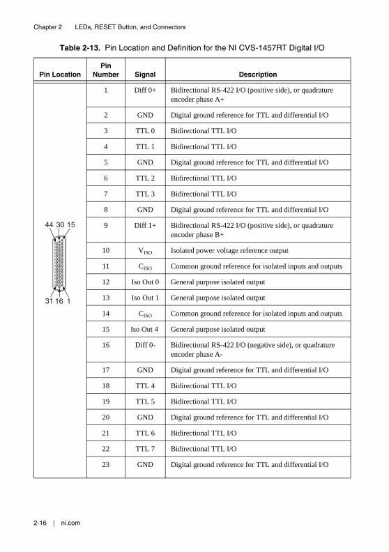
Digital I/OThe 44-pin Digital I/O port on the NI CVS-1457RT offers 8 isolated inputs, 8 isolated outputs, 2 bidirectional differential inputs (RS-422) or single-ended input lines which can be used with a quadrature encoder, and 8 bidirectional TTL lines. The Digital I/O port can be connected to any appropriate shielded device or connector block using a shielded cable. Refer to Table 2-13 for pin locations and functions.
Table 13. Ethernet Port Pin Descriptions
Pin Fast Ethernet Signal Gigabit Ethernet Signal
1 TX+ TX_A+
2 TX– TX_A–
3 RX+ RX_B+
4 NC TX_C+
5 NC TX_C–
6 RX– RX_B–
7 NC RX_D+
8 NC RX_D–
Pin 8
Pin 1
2-16 | ni.com
Chapter 2 LEDs, RESET Button, and Connectors
Table 2-13. Pin Location and Definition for the NI CVS-1457RT Digital I/O
Pin LocationPin
Number Signal Description
1 Diff 0+ Bidirectional RS-422 I/O (positive side), or quadrature encoder phase A+
2 GND Digital ground reference for TTL and differential I/O
3 TTL 0 Bidirectional TTL I/O
4 TTL 1 Bidirectional TTL I/O
5 GND Digital ground reference for TTL and differential I/O
6 TTL 2 Bidirectional TTL I/O
7 TTL 3 Bidirectional TTL I/O
8 GND Digital ground reference for TTL and differential I/O
9 Diff 1+ Bidirectional RS-422 I/O (positive side), or quadrature encoder phase B+
10 VISO Isolated power voltage reference output
11 CISO Common ground reference for isolated inputs and outputs
12 Iso Out 0 General purpose isolated output
13 Iso Out 1 General purpose isolated output
14 CISO Common ground reference for isolated inputs and outputs
15 Iso Out 4 General purpose isolated output
16 Diff 0- Bidirectional RS-422 I/O (negative side), or quadrature encoder phase A-
17 GND Digital ground reference for TTL and differential I/O
18 TTL 4 Bidirectional TTL I/O
19 TTL 5 Bidirectional TTL I/O
20 GND Digital ground reference for TTL and differential I/O
21 TTL 6 Bidirectional TTL I/O
22 TTL 7 Bidirectional TTL I/O
23 GND Digital ground reference for TTL and differential I/O
153044
11631
© National Instruments | 2-17
NI CVS-1457RT User Manual
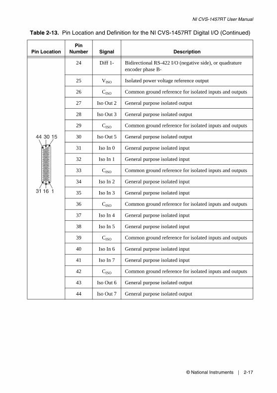
24 Diff 1- Bidirectional RS-422 I/O (negative side), or quadrature encoder phase B-
25 VISO Isolated power voltage reference output
26 CISO Common ground reference for isolated inputs and outputs
27 Iso Out 2 General purpose isolated output
28 Iso Out 3 General purpose isolated output
29 CISO Common ground reference for isolated inputs and outputs
30 Iso Out 5 General purpose isolated output
31 Iso In 0 General purpose isolated input
32 Iso In 1 General purpose isolated input
33 CISO Common ground reference for isolated inputs and outputs
34 Iso In 2 General purpose isolated input
35 Iso In 3 General purpose isolated input
36 CISO Common ground reference for isolated inputs and outputs
37 Iso In 4 General purpose isolated input
38 Iso In 5 General purpose isolated input
39 CISO Common ground reference for isolated inputs and outputs
40 Iso In 6 General purpose isolated input
41 Iso In 7 General purpose isolated input
42 CISO Common ground reference for isolated inputs and outputs
43 Iso Out 6 General purpose isolated output
44 Iso Out 7 General purpose isolated output
Table 2-13. Pin Location and Definition for the NI CVS-1457RT Digital I/O (Continued)
Pin LocationPin
Number Signal Description
153044
11631
© National Instruments | 3-1
3Deployment
This chapter provides guidelines for connecting the NI CVS-1457RT to a network.
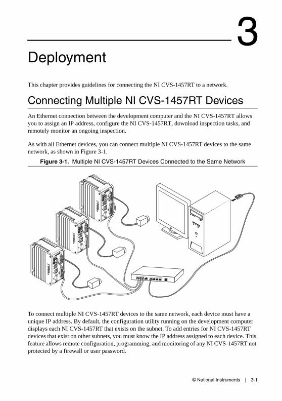
Connecting Multiple NI CVS-1457RT DevicesAn Ethernet connection between the development computer and the NI CVS-1457RT allows you to assign an IP address, configure the NI CVS-1457RT, download inspection tasks, and remotely monitor an ongoing inspection.
As with all Ethernet devices, you can connect multiple NI CVS-1457RT devices to the same network, as shown in Figure 3-1.
Figure 3-1. Multiple NI CVS-1457RT Devices Connected to the Same Network
To connect multiple NI CVS-1457RT devices to the same network, each device must have a unique IP address. By default, the configuration utility running on the development computer displays each NI CVS-1457RT that exists on the subnet. To add entries for NI CVS-1457RT devices that exist on other subnets, you must know the IP address assigned to each device. This feature allows remote configuration, programming, and monitoring of any NI CVS-1457RT not protected by a firewall or user password.
3-2 | ni.com
Chapter 3 Deployment
Use the NI CVS-1457RT primary Ethernet port media access control (MAC) address to uniquely identify each unit. The MAC address is printed on the top side of each NI CVS-1457RT.
The configuration environment on the host machine displays these values in order to distinguish one NI CVS-1457RT from another. In addition to distinguishing units based on MAC address, you can also assign each NI CVS-1457RT a descriptive name in the configuration environment. The default name for each device is NI-CVS1457RT-XXXXXXXX, where XXXXXXXX are the last eight digits of the MAC address.
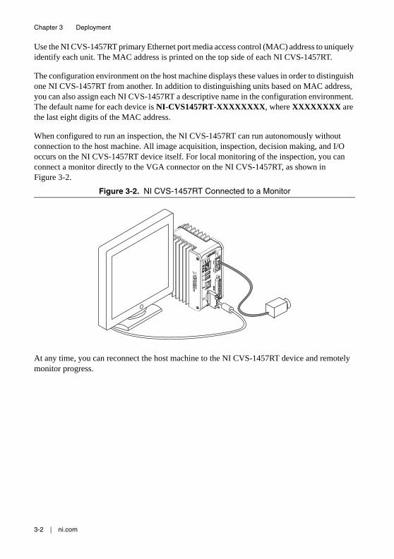
When configured to run an inspection, the NI CVS-1457RT can run autonomously without connection to the host machine. All image acquisition, inspection, decision making, and I/O occurs on the NI CVS-1457RT device itself. For local monitoring of the inspection, you can connect a monitor directly to the VGA connector on the NI CVS-1457RT, as shown in Figure 3-2.
Figure 3-2. NI CVS-1457RT Connected to a Monitor
At any time, you can reconnect the host machine to the NI CVS-1457RT device and remotely monitor progress.
© National Instruments | 4-1
4BIOS Configuration and System Recovery
You can change the configuration settings for the NI CVS-1457RT in the BIOS setup. The BIOS is the low-level interface between the hardware and PC software that configures and tests your hardware when you boot the system. The BIOS setup program includes menus for configuring settings and enabling features.
Most users do not need to use the BIOS setup program. The system ships with default settings that work well for most configurations.
Entering BIOS SetupTo start the BIOS setup program, complete the following steps:
1. Connect a VGA monitor to the VGA connector of the NI CVS-1457RT.
2. Connect a USB keyboard to one of the USB ports of the NI CVS-1457RT.
3. Power on or reboot the NI CVS-1457RT.
4. Immediately hold down the <F10> key until the message Please select boot device: appears onscreen.
5. Use the Down Arrow key to select Enter Setup and press <Enter>. The setup utility loads after a short delay.
The NI CVS-1457RT will enter the BIOS setup program and display the Main menu.
Use the following keys to navigate through the BIOS setup:
• Left, right, up, and down arrows—Use these keys to move between different setup menus. Press <Esc> to exit a submenu. Be sure number lock is off to use the numeric keypad arrows.
• <Enter>—Use this key either to open a submenu or display all available settings for the highlighted configuration option.
• <Esc>—Use this key to return to a parent menu of a submenu or cancel an outstanding selection. At the main menu, use this key to exit the BIOS setup.
• <+> and <–>—Use these keys to cycle between all available settings.
• <Tab>—Use this key to select time and date fields. When entering time and date information, you can also use the number keys to enter the time and date directly.
4-2 | ni.com
Chapter 4 BIOS Configuration and System Recovery
Press <F1> from any root menu to display more information about navigating the BIOS setup program.
Menu items listed in blue are changeable; menu items in gray are not changeable. A blue triangle next to a menu item indicates that the menu item contains a submenu.
The following sections describe the entries available in each BIOS menu.
Main MenuThe most commonly accessed and modified BIOS settings are in the Main setup menu. The Main setup menu includes the following settings:
• System Date—Changes the system date. The system date setting is stored in a battery-backed real-time clock. You can also change this setting from within MAX or Vision Builder AI.
• System Time—Changes the system time. The system time setting is stored in a battery-backed real-time clock. You can also change this setting from within Measurement & Automation Explorer (MAX) or Vision Builder AI.
Advanced MenuThis menu contains BIOS settings that normally do not require modification. If you have specific problems such as unbootable disks or resource conflicts, you may need to examine these settings.
The Advanced setup menu includes the following settings:
• CPU Configuration—Use this setting to bring up the CPU Configuration submenu. For information about the menu items within this submenu, refer to the CPU Configuration Submenu section.
• Power/Wake Configuration—Use this setting to bring up the Power/Wake Configuration submenu. For information about the menu items within this submenu, refer to the Power/Wake Configuration Submenu section.
• USB Configuration—Use this setting to bring up the USB Configuration submenu. For information about the menu items within this submenu, refer to the USB Configuration Submenu section.
• Serial Port Configuration—Use this setting to bring up the Serial Port Configuration submenu. For information about the menu items within this submenu, refer to the Serial Port Configuration Submenu section.
CPU Configuration SubmenuUse this submenu to apply custom configurations to the processor of the NI CVS-1457RT. Normally, you do not need to modify these settings, as the factory default settings provide the most compatible and optimal configuration possible.

© National Instruments | 4-3
NI CVS-1457RT User Manual
• Intel SpeedStep—Enables or disables Intel SpeedStep technology. Allows the clock speed of the processor to change dynamically to meet performance needs. The default setting is Enabled.
• Hyper-Threading—Enables or disables Intel Hyper-Threading technology. The default value is Disabled if the boot operating system is LabVIEW Real-Time and Enabled for other boot operating systems. Enabling Hyper-Threading increases performance for some applications by adding virtual CPU cores. Hyper-Threading can cause control algorithms to behave less deterministically.
• C-States—Enables or disables CPU power management. The default value is disabled when booting LabVIEW Real-Time, and enabled when booting other operating systems. Enabling C-States allows the processor to put idle CPU cores to sleep, allowing active cores to run at higher than base frequencies when Turbo Boost is enabled (if applicable). Enabling C-States can cause control algorithms to behave less deterministically.
Power/Wake Configuration SubmenuUse this submenu to apply alternate configurations to the power features of the chipset and controller. Normally, you do not need to modify these settings, as the factory default settings provide the most compatible and optimal configuration possible.
• Power Saving Mode—When Enabled, this setting disables select subsystems to reduce overall power usage.
• VGA Output—When set to Off, disables the VGA display output. The default value is On.
• USB VBus—When set to Off, disables the USB VBus power at the USB 2.0 host connector. The default value is On.
USB Configuration SubmenuUse this submenu to apply alternate configurations to the USB ports. Normally, you do not need to modify these settings, as the factory default settings provide the most compatible and optimal configuration possible.
• Legacy USB Support—Specifies whether or not legacy USB support is enabled. Legacy USB support refers to the ability to use a USB keyboard and mouse during system boot or in a legacy operating system such as DOS.
• USB transfer time-out—Specifies the number of seconds the POST waits for a USB mass storage device to complete a transaction. The default is 20 seconds.
• Device reset time-out—Specifies the number of seconds the POST waits for a USB mass storage device to start. The default is 20 seconds.
• Device power-up delay—Specifies the maximum amount of time a device can take to properly report itself during the POST. The default value is Auto. Alternatively, a Manual override setting can be used to support very slow USB devices.
4-4 | ni.com
Chapter 4 BIOS Configuration and System Recovery
Serial Port Configuration SubmenuUse this submenu to view the serial port configuration.
• Serial Port Configuration—Use this setting to bring up the Serial Port Configuration submenu. For information about the menu items within this submenu, refer to the section.
• Serial Port Console Redirection—Use this setting to bring up the Serial Port Console Redirection submenu. For information about the menu items within this submenu, refer to the section.
Serial Port ConfigurationUse this submenu to view the serial port configuration.
• RS485/RS232 Select—This setting selects the transceiver mode between RS-232 and RS-485. The default value is RS232.
• RS-485 Configuration—Use this menu to configure the RS-485/422 wire-mode and to enable or disable the RS-485 transceiver. The default value is Disabled.
Note When installed, the NI-Serial driver will enable the RS-485 Transceiver regardless of the state in the BIOS setup menu. The RS-485 Configuration setting is intended to be used with operating systems and drivers that are unaware of the registers to enable and disable the transceiver.
Serial Port Console RedirectionUse this submenu to view the serial port console redirection settings.
• Console Redirection—This setting enables and disables console redirection. The default value is Disabled.
• Console Redirection Settings—Use this menu to configure the terminal settings for console redirection.
LabVIEW RT MenuUse this menu to configure boot options for LabVIEW Real-Time.
Note The following LabVIEW RT Safe Mode, Reset IP Address, and Disable Startup VI settings override the behavior of the RESET button on the NI CVS-1457RT. Refer to the Using the RESET Button section of Chapter 2, LEDs, RESET Button, and Connectors, for more information. To use the settings from the RESET button, select Use Hardware Switch for each option.
• Boot Configuration—Selects whether the device should boot LabVIEW Real-Time or LabVIEW Real-Time Safe Mode. The default is LabVIEW RT.
• LabVIEW RT Safe Mode—Specifies whether to boot the device into safe mode. The default setting is Use Hardware Switch.
© National Instruments | 4-5
NI CVS-1457RT User Manual
• Reset IP Address—Specifies whether to reset the IP address of the device. Use this switch to reset the IP address of the primary Ethernet port to DHCP or a link-local address during LabVIEW Real-Time startup. The default setting is Use Hardware Switch.
Note By default, the target automatically attempts to connect to the network using DHCP. If the target is unable to initiate a DHCP connection, the target connects to the network with a link-local IP address (169.254.x.x).
• Disable Startup VI—Prevent VIs from automatically running at startup. Enable this setting if the device becomes inaccessible because of a startup VI. The default setting is Use Hardware Switch.
Boot MenuThis screen displays the boot order of devices associated with the NI CVS-1457RT. The BIOS proceeds down the Boot priority order list in search of a bootable device. Devices under the Excluded from boot order list will not be used for booting. If the BIOS fails to find any bootable device, the message Operating System Not Found is displayed, and the system halts.
• Setup Prompt Timeout—This setting specifies the amount of time the system waits for a BIOS Setup menu keypress (the <F10> key) in units of a second. The default value is 1 for a delay of 1 seconds.
• Bootup NumLock State—This setting specifies the power-on state of the keyboard NumLock setting. The default value is On.
• Quiet Boot—Determines if the BIOS should hide normal POST messages with the system manufacturer’s full screen logo during the boot up sequence. When Enabled, the BIOS displays the full screen logo during the boot up sequence, hiding normal POST messages. When Disabled, the BIOS displays normal POST messages instead of the full screen logo.
• PXE Network Boot—This setting specifies whether or not the PXE network boot agent is enabled. When this setting is enabled and the Boot Configuration in the LabVIEW RT menu is set to Windows/Other OS, the Intel Boot Agent is displayed in the Boot Option Priorities menu, allowing you to boot from a PXE server on the local subnet. Note that the Intel Boot Agent device names are preceded by IBA GE Slot 00c9 v1310 in the Boot Option Priorities menu. The system must be restarted for this setting to take effect. The default value is Disabled.
• Boot Option Priorities—These settings specify the order in which the BIOS checks for bootable devices, including the local hard disk drive, removable devices such as USB flash disk drives or USB CD-ROM drives, or the PXE network boot agent. The BIOS will first attempt to boot from the device associated with 1st Boot Device, followed by 2nd Boot Device, and 3rd Boot Device. If multiple boot devices are not present, the BIOS setup utility will not display all of these configuration options. To select a boot device, press <Enter> on the desired configuration option and select a boot device from the resulting menu. You can also disable certain boot devices by selecting Disabled.
4-6 | ni.com
Chapter 4 BIOS Configuration and System Recovery
Note Only one device of a given type will be shown in this list. If more than one device of the same type exists, use the Device BBS Priorities submenus to re-order the priority of devices of the same type.
The following submenus will be displayed if one or more bootable devices of the corresponding type is present:
• Hard Drive BBS Priorities—Use this setting to access the Hard Drive BBS Priorities submenu to re-order or disable bootable hard drive devices. Refer to the Hard Drive BBS Priorities Submenu section for more information.
• CD/DVD ROM Drive BBS Priorities—Use this setting to access the CD/DVD ROM Drive BBS Priorities submenu to re-order or disable bootable CD/DVD ROM drive devices. Refer to the CD/DVD ROM Drive BBS Priorities Submenu section for more information.
• Floppy Drive BBS Priorities—Use this setting to access the Floppy Drive BBS Priorities submenu to re-order or disable bootable floppy drive devices. Refer to the Floppy Drive BBS Priorities Submenu section for more information.
• Network Device BBS Priorities—Use this setting to access the Network Device BBS Priorities submenu to re-order or disable bootable network devices. Refer to the Network Device BBS Priorities Submenu section for more information.
Hard Drive BBS Priorities Submenu• Boot Option #1, Boot Option #2, Boot Option #3—These settings specify the boot
priority of hard drive devices. The highest priority device is displayed on the main Boot Option Priorities list. Optionally, each device can also be Disabled if the device should never be used as a boot device.
CD/DVD ROM Drive BBS Priorities Submenu• Boot Option #1, Boot Option #2, Boot Option #3—These settings specify the boot
priority of CD/DVD ROM drive devices. The highest priority device is displayed on the main Boot Option Priorities list. Optionally, each device can also be Disabled if the device should never be used as a boot device.
Floppy Drive BBS Priorities Submenu• Boot Option #1, Boot Option #2, Boot Option #3—These settings specify the boot
priority of floppy drive devices. The highest priority device is displayed on the main Boot Option Priorities list. Optionally, each device can also be Disabled if the device should never be used as a boot device.
Network Device BBS Priorities Submenu• Boot Option #1, Boot Option #2, Boot Option #3—These settings specify the boot
priority of network devices. The highest priority device is displayed on the main Boot

© National Instruments | 4-7
NI CVS-1457RT User Manual
Option Priorities list. Optionally, each device can also be Disabled if the device should never be used as a boot device.
Security MenuUse this menu to enable BIOS security options.
• Administrator Password—This setting specifies a password that must be entered to access the BIOS Setup Utility. If only the Administrator’s password is set, then this only limits access to the BIOS setup utility and is only asked for when entering the BIOS setup utility. By default, no password is specified.
• User Password—This setting specifies a password that must be entered to access the BIOS Setup Utility or to boot the system. If only the User’s password is set, then this is a power-on password and must be entered to boot or enter the BIOS setup utility. In the BIOS setup utility, the User has Administrator rights. By default, no password is specified.
Save & Exit MenuThe Save & Exit setup menu includes all available options for exiting, saving, and loading the BIOS default configuration. You can also press <F9> to load BIOS default settings and <F10> to save changes and exit setup.
The Save & Exit setup menu includes the following settings:
• Save Changes and Exit—Stores any changes made to BIOS settings in the battery-backed system CMOS. The setup program then exits and reboots the device.
• Discard Changes and Exit—Discards any changes made to BIOS settings. The setup program then exits and boots the device without rebooting first.
• Save Changes and Reset—Any changes made to BIOS settings are stored in NVRAM. The setup utility then exits and reboots the controller. The <F10> key can also be used to select this option.
• Discard Changes and Reset—Any changes made to BIOS settings during this session of the BIOS setup utility are discarded. The setup utility then exits and reboots the controller. The <Esc> key can also be used to select this option.
• Save Changes—Changes made to BIOS settings during this session are committed to NVRAM. The setup utility remains active, allowing further changes.
• Discard Changes—Any changes made to BIOS settings during this session of the BIOS setup utility are discarded. The BIOS setup continues to be active.
• Restore Defaults—This option restores all BIOS settings to the factory default. This option is useful if the controller exhibits unpredictable behavior due to an incorrect or inappropriate BIOS setting. Notice that any nondefault settings such as boot order, passwords, and so on, are also restored to their factory defaults. The <F9> key can also be used to select this option.
• Save As User Defaults—This option saves a copy of the current BIOS settings as the User Defaults. This option is useful for preserving custom BIOS setup configurations.

4-8 | ni.com
Chapter 4 BIOS Configuration and System Recovery
• Restore User Defaults—This option restores all BIOS settings to the user defaults. This option is useful for restoring previously preserved custom BIOS setup configurations.
• Boot Override—This option lists all possible bootable devices and allows the user to override the Boot Option Priorities list for the current boot. If no changes have been made to the BIOS setup options, the system will continue booting to the selected device without first rebooting. If BIOS setup options have been changed and saved, a reboot is required and the boot override selection will not be valid.
Restoring the NI CVS-1457RT to Factory Default ConditionComplete the following steps to restore the NI CVS-1457RT to its factory default condition.
1. Start the NI CVS-1457RT in safe mode. To start in safe mode, press the RESET button for more than 5 seconds.
2. Launch MAX.
3. In the MAX configuration tree, expand Remote Systems.
4. Right-click the name of the device you want to reformat and select Format Disk.
5. After the format completes, disable safe mode by pressing the RESET button for less than 5 seconds.
6. Refer to the NI CVS-1457RT Getting Started Guide for information about configuring the NI CVS-1457RT for your application.
© National Instruments | A-1
ATroubleshooting
This appendix provides instructions for troubleshooting the NI CVS-1457RT.
Software Configuration Problems
The NI CVS-1457RT Does Not Appear in MAX or in Vision Builder AIPossible causes and solutions:
• The NI CVS-1457RT may not be powered. Verify that there is system power to the device and that both the NI CVS-1457RT and the development computer are properly connected to the network. The PWR/FAULT LED should be lit green and the ACTIVITY/LINK LED on the primary network port should flash green when refreshing the list of devices in MAX or Vision Builder AI.
• The NI CVS-1457RT may have been configured on another network and then moved to the current network. Reconfigure the NI CVS-1457RT device for the current network.
Note Connect a monitor to the NI CVS-1457RT to view the current configuration settings of the device.
• Another device on the network is using the IP address assigned to the NI CVS-1457RT. This can happen when you assign the same static IP to two devices, you assign a static IP that is in the range of the IP address available for DHCP use on your network, or the DHCP server assigns the same IP address to another device. Either remove or reconfigure the other device, or reconfigure the NI CVS-1457RT to use a different IP address by putting it into the IP RESET state and restarting into the normal state.
• The cable you are using may be inappropriate for the speed of your network, causing network communication dropout. While 1,000 Mbps communication over short cables lengths can be achieved with the CAT5 cable commonly used for 10 and 100 Mbps, CAT5e and CAT6 cables are more reliable and recommended for 1,000 Mbps links. The NI CVS-1457RT has the ability to perform auto-crossover, allowing the use of straight or crossover Ethernet cables, independent of the connection configuration.
• The NI CVS-1457RT is configured to acquire an IP address from a DHCP server, but no DHCP server is available. By default, the target will automatically attempt to connect to the network using DHCP. If the target is unable to initiate a DHCP connection, the target connects to the network with a link-local IP address (169.254.x.x).
A-2 | ni.com
Appendix A Troubleshooting
• You may be experiencing firewall issues. If you are having difficulty detecting the system and setting up the NI CVS-1457RT on your network, you must configure the firewall to open the TCP/UDP ports used by the NI CVS-1457RT and the host machine. Refer to the following table for more information about TCP/UDP ports.
If your firewall is controlled remotely or you are unsure about configuring the firewall, contact your network administrator.
No Software is InstalledIf MAX or Vision Builder AI report that no software is installed, install application and driver software on the NI CVS-1457RT. Refer to the NI CVS-1457RT Getting Started Guide for installation instructions.
No Camera FoundVerify that the camera is properly connected and powered. If using PoE to power the camera, ensure that the PoE power input on the NI CVS-1457RT is properly connected to an adequate power supply. When a PoE-capable port is powered, the corresponding PoE status LED will illuminate. Verify that the link status LED on the NI CVS-1457RT is also illuminated to confirm a valid Ethernet connection to the camera. Verify that the cameras comply with the GigE Vision standard and, if using PoE, the Power over Ethernet standard (IEEE 802.3af).
Table A-1. TCP/UDP Ports Used by the NI CVS-1457RT
Port Type Details
3580 TCP/UDP Reserved as nati-svrloc (NAT-ServiceLocator). Used by Measurement & Automation Explorer (MAX) to locate remote targets.
7749 TCP Used for remote image display (not reserved).
7750 TCP Used for NI-IMAQdx remote configuration (not reserved).
3363 TCP/UDP Reserved as nati-vi-server (NATI VI Server). Used by Vision Builder for Automated Inspection to configure a remote target.
© National Instruments | A-3
NI CVS-1457RT User Manual
Hardware Problems
PWR/FAULT LED is RedThe NI CVS-1457RT has shut down due to an over-temperature condition.
Cannot Drive Isolated OutputsVerify that you have power connected to the VISO and CISO inputs on the NI CVS-1457RT isolated power connector and that the contact at the screw terminals is solid. Because these outputs are electrically isolated from the NI CVS-1457RT device main supply, they require power in addition to the NI CVS-1457RT main supply.
Runaway Startup ApplicationIf a runaway startup application causes the NI CVS-1457RT to become unresponsive, power off the NI CVS-1457RT and then restart it in either the NO APP state or the SAFE MODE state. Restarting the NI CVS-1457RT in the NO APP state prevents any VIs from running at startup. Restarting in the SAFE MODE state starts the NI CVS-1457RT in safe mode and does not launch the embedded LabVIEW RT engine.
LED Error IndicationsThe NI CVS-1457RT indicates specific error conditions by flashing the STATUS LED a specific number of times. Refer to STATUS LED section of Chapter 2, LEDs, RESET Button, and Connectors, for the STATUS LED indications.
PWR/FAULT LED Is Not Lit When the NI CVS-1457RT is Powered OnIf the system power supply is properly connected (polarity is not reversed) to the NI CVS-1457RT, but the PWR/FAULT LED does not light up, check that the power supply is within the specifications outlined in the NI CVS-1457RT Specifications. Using a power supply that is not within these specifications might result in an unresponsive or unstable system and could damage the NI CVS-1457RT.

© National Instruments | B-1
BMounting Information
This appendix provides the information necessary to create a custom mount for the NI CVS-1457RT. If you do not want to create a custom mount, a panel and DIN rail mount kit for the NI CVS-1457RT is available from National Instruments (part number 781740-01).
Mounting the NI CVS-1457RTIf you want to create a custom mount, Figures B-1 through B-4 provide dimensional drawings and clearance information for the NI CVS-1457RT.
Caution If you choose not to mount the NI CVS-1457RT on a DIN rail or flat surface, do not position the NI CVS-1457RT with the heat sinks resting on any surface. Doing so may cause the NI CVS-1457RT device to overheat. Refer to the NI CVS-1457RT Specifications for temperature specifications.
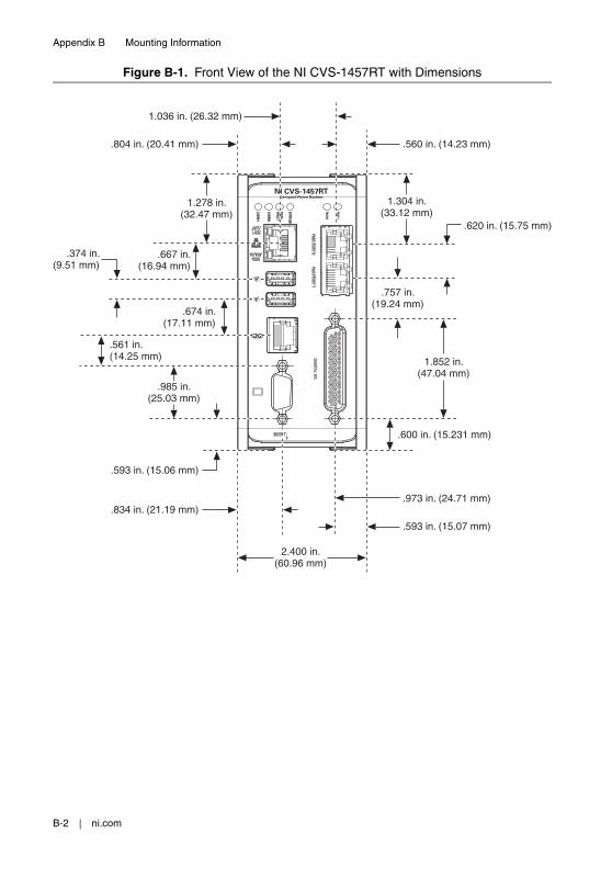
B-2 | ni.com
Appendix B Mounting Information
Figure B-1. Front View of the NI CVS-1457RT with Dimensions
NI CVS-1457RTCompact Vision System
.600 in. (15.231 mm)
1.852 in.(47.04 mm)
.757 in.(19.24 mm)
.620 in. (15.75 mm)
.560 in. (14.23 mm)
1.304 in.(33.12 mm)
.973 in. (24.71 mm)
.593 in. (15.07 mm)
.593 in. (15.06 mm)
.674 in.(17.11 mm)
.374 in.(9.51 mm)
.667 in.(16.94 mm)
.985 in.(25.03 mm)
.834 in. (21.19 mm)
2.400 in.(60.96 mm)
.804 in. (20.41 mm)
1.036 in. (26.32 mm)
1.278 in.(32.47 mm)
.561 in.(14.25 mm)
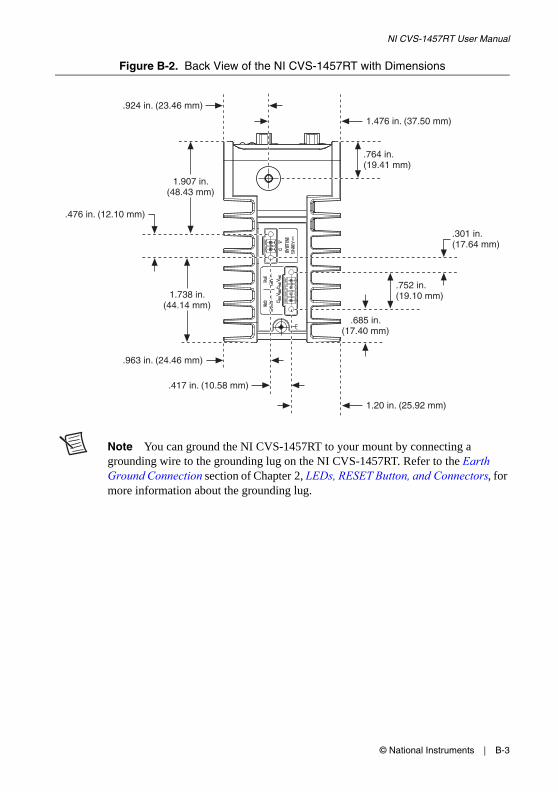
© National Instruments | B-3
NI CVS-1457RT User Manual
Figure B-2. Back View of the NI CVS-1457RT with Dimensions
Note You can ground the NI CVS-1457RT to your mount by connecting a grounding wire to the grounding lug on the NI CVS-1457RT. Refer to the Earth Ground Connection section of Chapter 2, LEDs, RESET Button, and Connectors, for more information about the grounding lug.
1.20 in. (25.92 mm)
.417 in. (10.58 mm)
.301 in.(17.64 mm)
.685 in.(17.40 mm)
.963 in. (24.46 mm)
.476 in. (12.10 mm)
1.738 in.(44.14 mm)
1.907 in.(48.43 mm)
.924 in. (23.46 mm)
1.476 in. (37.50 mm)
.752 in.(19.10 mm)
.764 in.(19.41 mm)
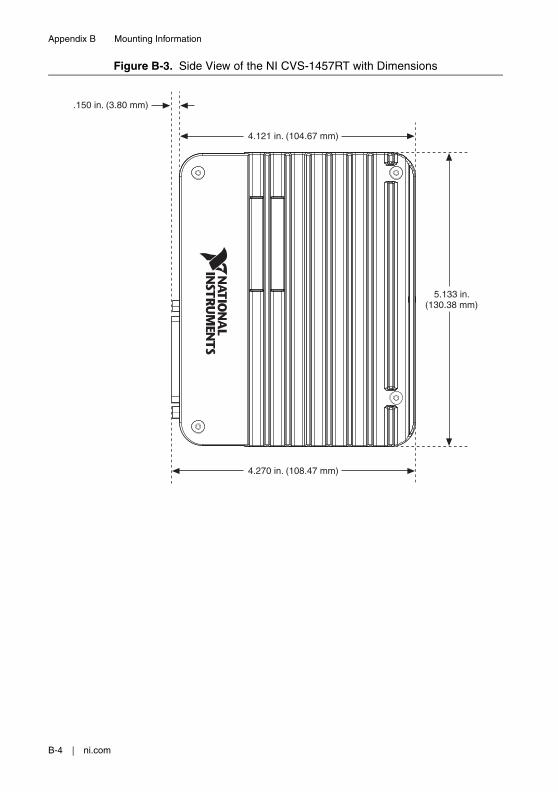
B-4 | ni.com
Appendix B Mounting Information
Figure B-3. Side View of the NI CVS-1457RT with Dimensions
5.133 in.(130.38 mm)
4.270 in. (108.47 mm)
.150 in. (3.80 mm)
4.121 in. (104.67 mm)
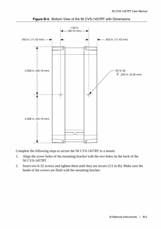
© National Instruments | B-5
NI CVS-1457RT User Manual
Figure B-4. Bottom View of the NI CVS-1457RT with Dimensions
Complete the following steps to secure the NI CVS-1457RT to a mount.
1. Align the screw holes of the mounting bracket with the two holes on the back of the NI CVS-1457RT.
2. Insert two 6-32 screws and tighten them until they are secure (3.5 in-lb). Make sure the heads of the screws are flush with the mounting bracket.
2X 6–32.250 in. (6.35 mm)
.450 in. (11.43 mm).450 in. (11.43 mm)
2.566 in. (65.19 mm)
2.566 in. (65.19 mm)
1.50 in.(38.10 mm)

B-6 | ni.com
Appendix B Mounting Information
Clearance RequirementsThe NI CVS-1457RT installation must meet the following space and cabling clearance requirements for optimum cooling:
• Allow 76.2 mm (3.0 in.) on the top and bottom of the NI CVS-1457RT for air circulation.
• Allow 50.8 mm (2.0 in.) on the sides of the NI CVS-1457RT for air circulation.
• Allow enough space in front of the NI CVS-1457RT to connect cables.
Refer to Figure B-5 for the clearance requirements for the NI CVS-1457RT.
Figure B-5. Clearance Requirements for the NI CVS-1457RT
50.8 mm(2.00 in.)
50.8 mm(2.00 in.)
76.2 mm(3.00 in.)
76.2 mm(3.00 in.)
NI CVS-1457RTCompact Vision System
RESET
DIG
ITAL I/O
10/100/1000
ACT/LINK
US
ER
1
US
ER
2
PW
R/
FAU
LT
STA
TUS
PoE
0
PoE
PO
RT 0
PoE
PO
RT 1
PoE
1

© National Instruments | C-1
CTechnical Support and Professional Services
Log in to your National Instruments ni.com User Profile to get personalized access to your services. Visit the following sections of ni.com for technical support and professional services:
• Support—Technical support at ni.com/support includes the following resources:
– Self-Help Technical Resources—For answers and solutions, visit ni.com/support for software drivers and updates, a searchable KnowledgeBase, product manuals, step-by-step troubleshooting wizards, thousands of example programs, tutorials, application notes, instrument drivers, and so on. Registered users also receive access to the NI Discussion Forums at ni.com/forums. NI Applications Engineers make sure every question submitted online receives an answer.
– Standard Service Program Membership—This program entitles members to direct access to NI Applications Engineers via phone and email for one-to-one technical support, as well as exclusive access to self-paced online training modules at ni.com/self-paced-training. All customers automatically receive a one-year membership in the Standard Service Program (SSP) with the purchase of most software products and bundles including NI Developer Suite. NI also offers flexible extended contract options that guarantee your SSP benefits are available without interruption for as long as you need them. Visit ni.com/ssp for more information.
For information about other technical support options in your area, visit ni.com/services, or contact your local office at ni.com/contact.
• Training and Certification—Visit ni.com/training for training and certification program information. You can also register for instructor-led, hands-on courses at locations around the world.
• System Integration—If you have time constraints, limited in-house technical resources, or other project challenges, National Instruments Alliance Partner members can help. To learn more, call your local NI office or visit ni.com/alliance.
• Declaration of Conformity (DoC)—A DoC is our claim of compliance with the Council of the European Communities using the manufacturer’s declaration of conformity. This system affords the user protection for electromagnetic compatibility (EMC) and product safety. You can obtain the DoC for your product by visiting ni.com/certification.
You also can visit the Worldwide Offices section of ni.com/niglobal to access the branch office Web sites, which provide up-to-date contact information, support phone numbers, email addresses, and current events.