nfinity 3:1 power system - amazon web services · pdf filepower to your equipment, protecting...
TRANSCRIPT

POWER PROTECTION
Nfinity™ 3:1 Power System
USER MANUAL380/400/415V50/60Hz
4 to 20 kVA


Table of Contents
IMPORTANT SAFETY INSTRUCTIONS . . . . . . . . . . . . . . . . . . . . . . . . . . . . . . . . . . . . . . . . . 1GLOSSARY OF SYMBOLS. . . . . . . . . . . . . . . . . . . . . . . . . . . . . . . . . . . . . . . . . . . . . . . . . 2
Introduction . . . . . . . . . . . . . . . . . . . . . . . . . . . . . . . . . . . . . . . . . . . . . . . . 3GENERAL DESCRIPTION . . . . . . . . . . . . . . . . . . . . . . . . . . . . . . . . . . . . . . . . . . . . . . . . . . 4
System Description . . . . . . . . . . . . . . . . . . . . . . . . . . . . . . . . . . . . . . . . . . . . . . . . . 4Features . . . . . . . . . . . . . . . . . . . . . . . . . . . . . . . . . . . . . . . . . . . . . . . . . . . . . . . . . . . . . 4Standard Components . . . . . . . . . . . . . . . . . . . . . . . . . . . . . . . . . . . . . . . . . . . . . . . . . . 4Communications . . . . . . . . . . . . . . . . . . . . . . . . . . . . . . . . . . . . . . . . . . . . . . . . . . . . . . . 4
MODES OF OPERATION . . . . . . . . . . . . . . . . . . . . . . . . . . . . . . . . . . . . . . . . . . . . . . . . . . 6Normal Mode . . . . . . . . . . . . . . . . . . . . . . . . . . . . . . . . . . . . . . . . . . . . . . . . . . . . . . . . . 6Back-Up Mode. . . . . . . . . . . . . . . . . . . . . . . . . . . . . . . . . . . . . . . . . . . . . . . . . . . . . . . . . 6Auto Restart Mode . . . . . . . . . . . . . . . . . . . . . . . . . . . . . . . . . . . . . . . . . . . . . . . . . . . . . 6Recharge Mode . . . . . . . . . . . . . . . . . . . . . . . . . . . . . . . . . . . . . . . . . . . . . . . . . . . . . . . . 6Bypass Mode . . . . . . . . . . . . . . . . . . . . . . . . . . . . . . . . . . . . . . . . . . . . . . . . . . . . . . . . . . 6
MAJOR COMPONENTS . . . . . . . . . . . . . . . . . . . . . . . . . . . . . . . . . . . . . . . . . . . . . . . . . . . 7Unit Frame . . . . . . . . . . . . . . . . . . . . . . . . . . . . . . . . . . . . . . . . . . . . . . . . . . . . . . . 7User Interface Module . . . . . . . . . . . . . . . . . . . . . . . . . . . . . . . . . . . . . . . . . . . . . . 8System Control Module . . . . . . . . . . . . . . . . . . . . . . . . . . . . . . . . . . . . . . . . . . . . . 8Power Module . . . . . . . . . . . . . . . . . . . . . . . . . . . . . . . . . . . . . . . . . . . . . . . . . . . . . 9Battery Module . . . . . . . . . . . . . . . . . . . . . . . . . . . . . . . . . . . . . . . . . . . . . . . . . . . . 9
Installation . . . . . . . . . . . . . . . . . . . . . . . . . . . . . . . . . . . . . . . . . . . . . . . . 11PREPARATION . . . . . . . . . . . . . . . . . . . . . . . . . . . . . . . . . . . . . . . . . . . . . . . . . . . . . . . . 12
Inspection . . . . . . . . . . . . . . . . . . . . . . . . . . . . . . . . . . . . . . . . . . . . . . . . . . . . . . . 12Environment . . . . . . . . . . . . . . . . . . . . . . . . . . . . . . . . . . . . . . . . . . . . . . . . . . . . . 12Required Setup Equipment . . . . . . . . . . . . . . . . . . . . . . . . . . . . . . . . . . . . . . . . . 12Site Preparation . . . . . . . . . . . . . . . . . . . . . . . . . . . . . . . . . . . . . . . . . . . . . . . . . . 12
UNLOADING . . . . . . . . . . . . . . . . . . . . . . . . . . . . . . . . . . . . . . . . . . . . . . . . . . . . . . . . . . 13Unloading the UPS . . . . . . . . . . . . . . . . . . . . . . . . . . . . . . . . . . . . . . . . . . . . . . . . 13
Stationary Mounting . . . . . . . . . . . . . . . . . . . . . . . . . . . . . . . . . . . . . . . . . . . . . . . . . . 14
i

CABLE INSTALLATION . . . . . . . . . . . . . . . . . . . . . . . . . . . . . . . . . . . . . . . . . . . . . . . . . . 15Wiring Preparation . . . . . . . . . . . . . . . . . . . . . . . . . . . . . . . . . . . . . . . . . . . . . . . . 15
Removing the Cover Plates . . . . . . . . . . . . . . . . . . . . . . . . . . . . . . . . . . . . . . . . . . . . . 15Configuring the Bypass Voltage (TB2) (Transformer Models Only) . . . . . . . . . . . . . 15
Power Cable Installation . . . . . . . . . . . . . . . . . . . . . . . . . . . . . . . . . . . . . . . . . . . 15Input Wiring (TB1) . . . . . . . . . . . . . . . . . . . . . . . . . . . . . . . . . . . . . . . . . . . . . . . . 16Output Wiring (TB3). . . . . . . . . . . . . . . . . . . . . . . . . . . . . . . . . . . . . . . . . . . . . . . 16
Without transformer . . . . . . . . . . . . . . . . . . . . . . . . . . . . . . . . . . . . . . . . . . . . . . . . . . 16With transformer . . . . . . . . . . . . . . . . . . . . . . . . . . . . . . . . . . . . . . . . . . . . . . . . . . . . . 16
REPO Switch. . . . . . . . . . . . . . . . . . . . . . . . . . . . . . . . . . . . . . . . . . . . . . . . . . . . . 17COMMUNICATIONS . . . . . . . . . . . . . . . . . . . . . . . . . . . . . . . . . . . . . . . . . . . . . . . . . . . . . 18
COM Ports. . . . . . . . . . . . . . . . . . . . . . . . . . . . . . . . . . . . . . . . . . . . . . . . . . . . . . . 18COM 1 - Relay Contacts . . . . . . . . . . . . . . . . . . . . . . . . . . . . . . . . . . . . . . . . . . . . . . . . 18COM 2 - Serial . . . . . . . . . . . . . . . . . . . . . . . . . . . . . . . . . . . . . . . . . . . . . . . . . . . . . . . 18
Intellislot™ Ports . . . . . . . . . . . . . . . . . . . . . . . . . . . . . . . . . . . . . . . . . . . . . . . . . 18
Operating Instructions . . . . . . . . . . . . . . . . . . . . . . . . . . . . . . . . . . . . . . 19CONTROLS AND INDICATORS . . . . . . . . . . . . . . . . . . . . . . . . . . . . . . . . . . . . . . . . . . . . . 20
Display Controls . . . . . . . . . . . . . . . . . . . . . . . . . . . . . . . . . . . . . . . . . . . . . . . . . . 20Buttons . . . . . . . . . . . . . . . . . . . . . . . . . . . . . . . . . . . . . . . . . . . . . . . . . . . . . . . . . . . . . 20Fault/Warning and Status LEDs . . . . . . . . . . . . . . . . . . . . . . . . . . . . . . . . . . . . . . . . 20
Navigating the Menu . . . . . . . . . . . . . . . . . . . . . . . . . . . . . . . . . . . . . . . . . . . . . . 22OPERATING PROCEDURES . . . . . . . . . . . . . . . . . . . . . . . . . . . . . . . . . . . . . . . . . . . . . . . 23
Start-Up and Initialization. . . . . . . . . . . . . . . . . . . . . . . . . . . . . . . . . . . . . . . . . . 23Shutting Down the UPS . . . . . . . . . . . . . . . . . . . . . . . . . . . . . . . . . . . . . . . . . . . . 23Manual Transfer to Bypass . . . . . . . . . . . . . . . . . . . . . . . . . . . . . . . . . . . . . . . . . 23
MAIN MENU. . . . . . . . . . . . . . . . . . . . . . . . . . . . . . . . . . . . . . . . . . . . . . . . . . . . . . . . . . 24UPS Status Screen . . . . . . . . . . . . . . . . . . . . . . . . . . . . . . . . . . . . . . . . . . . . . . . . 25UPS Configuration Screen - Review Settings Menu. . . . . . . . . . . . . . . . . . . . . . 26UPS Configuration Screen - Change Settings Menu . . . . . . . . . . . . . . . . . . . . . 27UPS Configuration Screen - Service Mode Menu . . . . . . . . . . . . . . . . . . . . . . . . 31Display Date/Time . . . . . . . . . . . . . . . . . . . . . . . . . . . . . . . . . . . . . . . . . . . . . . . . 31Event Log . . . . . . . . . . . . . . . . . . . . . . . . . . . . . . . . . . . . . . . . . . . . . . . . . . . . . . . 32Alarm Log . . . . . . . . . . . . . . . . . . . . . . . . . . . . . . . . . . . . . . . . . . . . . . . . . . . . . . . 32Transfer to Bypass . . . . . . . . . . . . . . . . . . . . . . . . . . . . . . . . . . . . . . . . . . . . . . . . 32Module Replacement. . . . . . . . . . . . . . . . . . . . . . . . . . . . . . . . . . . . . . . . . . . . . . . 33Tools. . . . . . . . . . . . . . . . . . . . . . . . . . . . . . . . . . . . . . . . . . . . . . . . . . . . . . . . . . . . 34
Troubleshooting . . . . . . . . . . . . . . . . . . . . . . . . . . . . . . . . . . . . . . . . . . . 35
ii

ALARM MESSAGES . . . . . . . . . . . . . . . . . . . . . . . . . . . . . . . . . . . . . . . . . . . . . . . . . . . . 36MODULE LED INDICATION . . . . . . . . . . . . . . . . . . . . . . . . . . . . . . . . . . . . . . . . . . . . . . . 39MODULE REPLACEMENT . . . . . . . . . . . . . . . . . . . . . . . . . . . . . . . . . . . . . . . . . . . . . . . . 40
Removing Modules . . . . . . . . . . . . . . . . . . . . . . . . . . . . . . . . . . . . . . . . . . . . . . . . 40Replacing Modules . . . . . . . . . . . . . . . . . . . . . . . . . . . . . . . . . . . . . . . . . . . . . . . . 41Replacing the User Interface . . . . . . . . . . . . . . . . . . . . . . . . . . . . . . . . . . . . . . . . 41
Maintenance . . . . . . . . . . . . . . . . . . . . . . . . . . . . . . . . . . . . . . . . . . . . . . 43MAINTENANCE . . . . . . . . . . . . . . . . . . . . . . . . . . . . . . . . . . . . . . . . . . . . . . . . . . . . . . . . 44
Proper Care . . . . . . . . . . . . . . . . . . . . . . . . . . . . . . . . . . . . . . . . . . . . . . . . . . . . . . 44Scheduled Maintenance . . . . . . . . . . . . . . . . . . . . . . . . . . . . . . . . . . . . . . . . . . . . 44Replacing Fan Filters . . . . . . . . . . . . . . . . . . . . . . . . . . . . . . . . . . . . . . . . . . . . . . 44
Reference. . . . . . . . . . . . . . . . . . . . . . . . . . . . . . . . . . . . . . . . . . . . . . . . . 45SPECIFICATIONS . . . . . . . . . . . . . . . . . . . . . . . . . . . . . . . . . . . . . . . . . . . . . . . . . . . . . . 46APPROXIMATE BATTERY RUN TIMES . . . . . . . . . . . . . . . . . . . . . . . . . . . . . . . . . . . . . . . 47
12 Bay Frame, Internal and External (minutes) . . . . . . . . . . . . . . . . . . . . . . . . 47
iii

iv
IMPORTANT SAFETY INSTRUCTIONS
SAVE THESE INSTRUCTIONSThis manual contains important instructions thatshould be closely followed during installation andmaintenance of this UPS unit and during theinstallation and replacement of power, control andbattery modules.
This product is designed for Commercial /Industrial use only. This product is not intended foruse with life support and other designated “critical”devices. Maximum load must not exceed thatshown on the UPS rating label.
Observe the following precautions when workingwith batteries:
• CAUTION: DO NOT dispose ofbattery modules in a fire; the batterymodule may explode.
• CAUTION: DO NOT open ormutilate batteries; released electrolyte isharmful to skin and eyes, and may be toxic.
• CAUTION: A battery can present arisk of electrical shock and high shortcircuit current. The following precautionsshould be observed when working onbatteries:• Remove watches, rings or other metal
objects.• Use tools with insulated handles.
• CAUTION: Lead-acid batteriescontain hazardous toxic materials. Handle,transport, and recycle in accordance withlocal regulations.
This UPS is designed for use on properlygrounded 380/400/415 VAC 50/60 Hz supply, forinstallation by qualified personnel. This UPS isintended to be installed by a qualified / certifiedelectrician who must review and approve customersupplied wiring, circuit breakers, intended loadsand verify correct input, output and earthconnections to ensure compliance with technicalstandards and local electrical codes of practice.Installation instructions and warning notices, onlyfor use by qualified personnel, can be found inInstallation on page 10.
ELECTROMAGNETIC COMPATIBILITY—ThisUPS complies with the requirements of the EMCdirective 89/336/EEC and the published technicalstandards. Continued compliance requiresinstallation in accordance with these instructionsand use of manufacturer approved accessoriesonly.
Operate the UPS in an indoor environment only inan ambient temperature range of 0°C to +40°C(32°F to +104°F). Install it in a clean environment,free from conductive contaminants, moisture,flammable liquids, gases, or corrosive substances.
Turn the UPS off and isolate the UPS beforecleaning. Use only a soft cloth, never liquid oraerosol cleaners. Keep the front and rear ventsfree of dust accumulation that could restrict airflow.
Never block or insert any object into the ventilationholes or other openings.
This UPS contains user replaceable modules. Noattempts should be made to access the interior ofany module. See Module Replacement onpage 39.
WARNINGLethal voltages may be present within this uniteven when it is apparently not operating.Observe all cautions and warnings in thismanual. Failure to do so MAY result in seriousinjury or death. Never work alone.
WARNINGThis UPS should not be supplied from electricalpower systems of the “IT” (Impedance à Terre)type. (IEC 364 - ELECTRICAL INSTALLATIONOF BUILDINGS).
1

GLOSSARY OF SYMBOLS
Risk of electrical shock
Indicates caution followed by important instructions
AC input
AC output
Requests the user to consult the manual
Indicates the unit contains a valve-regulated lead acidbattery
Recycle
DC voltage
Equipment earthing conductor
Bonded to earth
AC voltage
OFF
ON
Standby
No telecommunication connection
Locked position
Unlocked position
Contact closure signals
Serial communications
i
2

IntroductionGeneral DescriptionModes Of OperationMajor Components
3

GENERAL DESCRIPTION
Congratulations on your purchase of Liebert’sNfinity™ Uninterruptible Power System (UPS). Aswith every Liebert product, we stand behind ourquality. If you have any questions concerning thisUPS, please feel free to contact your local salesrepresentative, or call the appropriate technicalsupport number listed on the back of this manual.
To ensure proper installation and operation of thisunit, please read this manual thoroughly.
While installation must be completed by aqualified/certified electrician, general operationmay be performed without special training.
System DescriptionThe Liebert Nfinity Power System is a modularUPS intended for use with workstations, servers,network, telecom or other sensitive electronicequipment. It provides continuous, high-quality ACpower to your equipment, protecting it from anypower disturbances due to blackouts, brownouts,surges or noise interference.
The Nfinity modular UPS was designed to providemaximum system availability to business criticalequipment. Nfinity is an easily adaptable UPSsystem. By simply installing additional power orbattery modules you can expand your currentsystem capacity or extend your back-up runtime.
Nfinity has a comprehensive user interface thatcan be configured according to the user’spreference. It also informs the user of details onthe status of the UPS, and keeps a log of events.
Features• Up to 20 kVA of modular back-up power• Continuous power conditioning• A user-friendly interface for custom
configuration• Continuous system monitoring• Warning alarms and event logs• Internal automatic & manual bypass• Output transformer for isolation (optional)
Standard Components• Power Modules - for power conditioning• Battery Modules - for back-up power• System Control Modules - for system
monitoring and communications• LCD for comprehensive user indications and
programmable controls
Communications• Dry contacts• RS-232• Optional communications via Intellislot™
communication ports
4

ESC
!
COM1 COM2
Port 1 Port 2 Port 3 Port 4
User Interface Control EnableSwitch (SW2)
PowerModule
Bays
BatteryModule
Bays
ManualBypassSwitch(SW1)
IntakeCooling
Fans(TransformerOption Only)
DB-9CommunicationPorts
Output PowerTerminal
Input PowerTerminal
External BatteryConnection
REPOTerminal
Intellislot™Communications Ports
220/240 Jumper(TransformerOption Only)
Input EarthTerminal
Input CircuitBreaker (CB1)
Backwith access plates removed
Frontwith bezels removed
5

MODES OF OPERATION
The Nfinity UPS is designed to operate as a true on-line system in the following modes:
Normal ModeThe Power Module’s power factor correction circuitryderives power from the AC Mains and suppliesregulated DC power to the inverter. The module’sinverter regenerates precise AC power to supply theconnected equipment. The battery charger maintainsa float-charge on the battery.
Back-Up ModeWhen AC Mains fails, the connected equipment issupplied power by the inverter, which obtainsenergy from the battery modules. The connectedload will not be interrupted during the failure orrestoration of the AC Mains source.
Auto Restart ModeAfter a power outage and complete batterydischarge, once the AC Mains is restored, theUPS will automatically restart and resumesupplying power to the connected equipment. Thisfeature is enabled at the factory, but can bedisabled by the user. The user can also programtwo auto restart delay settings:
1. Battery capacity level (%)2. Countdown timer
Recharge ModeWhen AC Mains is restored, the unit will thenautomatically recharge the battery modules untilthey are fully charged.
Bypass ModeThe bypass provides an alternate path for power tothe connected equipment and operates in thefollowing manner:
• AutomaticIn the event of an internal fault or should theinverter overload capacity be exceeded, theUPS performs an automatic transfer of theconnected equipment from the inverter to thebypass source.
• ManualShould the UPS need to be taken out ofservice for limited maintenance or repair,manual activation of the bypass will cause animmediate transfer of the equipment from theinverter to the bypass source.
220V - standard230/240V - optional
MANUALBYPASS
POWER
CONTROL
EMIFilter
POWERMODULE(S)
EMIFilter
OUTPUT &BYPASS
CONTACTOR
SYSTEMCONTROLMODULE
SYSTEMCONTROLMODULE
CONTROLINTERFACE
USERINTERFACE
BATTERYMODULE(S)
COMMUNICATIONS
OUTPUTTRANSFORMER
INPUT OUTPUT
6

MAJOR COMPONENTS
The following is a general description of eachcomponent and its functions. Please review thissection carefully, as it will give you a betterunderstanding as to how Nfinity operates.
Unit FrameNfinity’s frame houses all of the other systemcomponents. Looking at the front of Nfinity, one willsee a series of plastic bezels. By grasping thesebezels from the side and pulling out, you willremove the bezel to reveal the Battery / PowerModule bays. The bottom bezel covers the coolingfans and the Manual Bypass Switch.
The User Interface Module is located above thePower / Battery Module bays for easy access.From here the user may find out variousinformation about Nfinity’s condition. By movingthe User Interface and setting it on top of theframe, you will see the System Control Modulebays.
Nfinity’s frame with bezels removed(Power Module and Battery Module extended for illustrationonly. Extending more than one module at a time could causethe unit to tip over).
ESC
!
7

User Interface ModuleThe User Interface Module is the primary source ofcommunication between the UPS and the user.From the interface, the user can:
• View the status of the UPS• Custom configure the system• Review the event log to assist with
troubleshooting• Enable / disable the output power• Silence the audible alarm
For a more detailed explanation on how to operatethe User Interface module, see Controls AndIndicators on page 19.
User Interface Module
System Control ModuleThe System Control Module is the communicativebackbone of the UPS. It gathers input from allmodules and processes the data to control theoperation of the system — including monitoring thecondition of each module. An optional secondSystem Control Module can be installed to providefull system redundancy (operation andcommunication), in the unlikely event a ControlModule should fail.
Under normal operation, the Status LED (green)will blink and the Fault LED (amber) will be off. Forany condition other than this, checkTroubleshooting on page 34.
System Control Module
Lever
Fault LED
Status LED
Fasteners
8

Power ModuleThe Power Module maintains the condition ofpower in the Nfinity UPS. Each module is anindependent 4 kVA unit, consisting of a rectifier,battery charger, and inverter, with associatedmonitoring and control-circuitry. The modules areparalleled to provide greater capacity and/orredundancy. Modules may be added or replacedon-line with no interruption or danger to theconnected equipment.
Battery ModuleThe Battery Modules provide back-up power in theevent of input AC Mains failure. Each modulecontains a quantity of ten individual 12-volt valveregulated (VRLA) battery blocks with associatedmonitoring and controls to isolate the batterymodule in the event of a battery failure. Themodules are paralleled to provide greater back-uptime and/or redundancy. Modules may be addedor replaced on-line with no interruption or dangerto the connected equipment.
Under normal operation, the Status LED (green) will blink and the Fault LED (amber) will be off. For anycondition other than this, check the Troubleshooting section in this manual.
Power Module Battery Module
Lever
Cooling FanFault LEDStatus LED
Fastener
Shipping screws
FRONTFRONT
9

10

InstallationPreparation
UnloadingCable InstallationCommunications
11

PREPARATION
These installation instructions provide all theinformation needed for positioning the UPS(including environmental requirements) and forconnecting the input and output power cables.
InspectionUpon receiving the UPS, examine the packagingfor any signs of mishandling or damage. If anydamage is noted, call your local Liebertrepresentative and/or notify your carrier.
EnvironmentOperating in temperatures above 25°C (77°F) willreduce battery life. The UPS environment must befree of conductive contaminants and excessivemoisture (water condensation, flammable vapors,chemical fumes, or corrosive gasses and liquids).
Required SetupEquipmentThe tools below are required to properly set upyour UPS:
• pallet jack• 13mm (1/2in) spanner• torque wrench (Nm)• flathead screwdriver• #2 Phillips screwdriver
Site PreparationWhen deciding where to locate your UPS,consider the weight and size of the unit. Make surethat the structural integrity of the floor canwithstand the weight of a fully loaded unit. Refer tothe table below for size and fully populated weightconsiderations:
Check to make sure that your UPS will be locatedin a well-ventilated area with at least 300 mm(12 in) behind it. The UPS is force cooled with theaid of internal cooling fans. Cooling air enters fromthe front of the UPS and is exhausted throughventilation grilles in the back. It should also have atleast 1 metre (39in) in front in order to changemodules if necessary.
The unit frame is bolted to the shipping pallet toensure safety. It is recommended that a pallet jackbe used to transport the unit to its operatinglocation (prior to unbolting the unit).
Model Max Weightkg (lb)
H x W x Dmm (in)
12 bay withtransformer
539(1188)
1346x508x711(53x20x28)
12 bay withouttransformer
459(1011)
1346x508x711(53x20x28)
1 metre(39 in)
300 mm(12 in)
12

UNLOADING
Unloading the UPSCAUTION: This UPS is very heavy (seeweight in Site Preparation on page 11). At leasttwo people should be present to unload it from thepallet.
1. Once the UPS is near the desired operatinglocation, remove the cardboard cover.
2. Use a 13mm (1/2in) spanner to remove thefour mounting bolts from the pallet brackets.Remove mounting brackets from the palletand UPS. Keep brackets for futuretransportation of UPS, or for additional stabilityonce in place.
3. Remove the metal ramp from the bottom of theUPS, rotating it. Fit ramp in pallet slot asshown above.
ESC
!
13

4. Using two people, slowly move the UPS downthe ramp until the UPS is on level ground.
5. Once the UPS is in its desired location, adjustthe leveling feet to secure its position.
Stationary MountingAdditional stability can be added by bolting themounting brackets (used in shipping) to the floor.
For greater stability, use a higher-grade bolt. Referto the dimensions below when drilling holes forstationary mounting.
13mm(1/2in)
711 mm(28")
7.94 mm (5/16")diameter6 places
Optional Stationary Mounting
Cen
tre
Lin
e
120 mm(4.75")
120 mm(4.75")
14

CABLE INSTALLATION
Wiring Preparation
Removing the Cover PlatesOn the back ofthe UPS, coverplates are overthe input andoutput terminals,as shown onright. Removethese using aPhillipsscrewdriver. Keepscrews and platesto one side.
Configuring the Bypass Voltage(TB2) (Transformer Models Only)The UPS voltage is factory set to 230V / 240V.Should the user have an AC Mains supply of 220V,the bypass voltage jumper will have to be changedto ensure correct output voltage during bypassmode.
Power Cable InstallationRefer to the chart below when selecting cables:
NOTES
If an output transformer is fitted and the start-up ison bypass the UPS has a six-cycle inrush currentthat is 20 times the rated output current. This mustbe taken into account when selecting the overloadprotection device at the AC input supplydistribution point. To avoid random tripping on startup, it is recommended that the AC input supply beprotected with a circuit breaker capable ofwithstanding this initial inrush. (An MCB rated tocurve “D” or specified as being “Type 4” (Britishstandard) is suitable for this purpose).
This UPS is fitted with EMI suppression filters.Earth leakage current is less than 40mA. Transientand steady state earth leakage currents may occurwhen starting the equipment. This should be takeninto account when selecting instantaneous RCCBor RCCD devices, as the earth leakage currents ofboth the UPS and load will be carried by these.
An overcurrent protection device (circuit breaker orfused disconnect switch) must be installed for theAC output.
This UPS does not incorporate automatic backfeed protection. A warning label must be fitted toall primary power isolators stating: ISOLATEUNINTERRUPTIBLE POWER SYSTEM (UPS)BEFORE WORKING ON THIS CIRCUIT. Earth inaccordance with local electrical codes.
WARNINGPlease read this section thoroughly beforeattempting to install wiring to this unit.
Be sure that the unit is not connected to any ACMains power source before installing any wiringto this unit. This UPS should be installed by aqualified / certified electrician.
Remove Cover Plates
220 V 230/240 V(default)
OR
Bypass Voltage Jumper
12 Bay Power Cable and Protection Ratings
Input / Output Voltage
380/220V
400/230V
415/240V
Max Input Current PerPhase in UPS Mode
30 A 28 A 27 A
Input Protection - 3 Pole 100 A 90 A 90 AMax Output Current 91 A 87 A 83 ANOTE: Bypass is supplied via phase R; thereforefeeder cable must be rated for single phase current.Terminal Details Max: 35 mm² (2 AWG)
Min: 16 mm² (6 AWG)Torque Rating: 2.5-3.0 Nm
90°C rated copper wire is recommended
15

Input Wiring (TB1)To connect the input wiring, follow these steps:
Note: Input wiring must be installed using conduit.
1. Locate the inputwiring access,remove theknockout andpull the threeinput wiresthrough it,allowing someslack forinstallation.
2. Secure theconduit to the rear panel of the UPS.
3. Input Power cables connect to screw terminalson the Input Terminal Block located to the rightof the Bypass Voltage Terminal. First insert theearth wire through the earth lug and tighten itto the proper torque value 2.5 - 3.0 Nm(22 - 26 in-lb). Then connect the wires to theblock connections as shown below. Using atorque wrench, turn the screws clockwise untiltightened to the proper torque value.
Output Wiring (TB3)
Without transformer
With transformer
Note the Neutral / Earth jumper on the terminal above.
Note
R phase connects to U terminal
S phase connects to V terminal
T phase connects to W terminal
TB1
U
V
W
N TRANSFORMER MODELS
The Nfinity UPS contains an isolationtransformer that generates a neutral conductorfor the connected equipment. The UPS is aseparately derived source and contains aneutral to earth bonding jumper. Remove thisearth/neutral link when required by localelectrical codes.
TB3
2
3
1
230V/240V
TB3 1
2
3220V
4
230V/240V
16
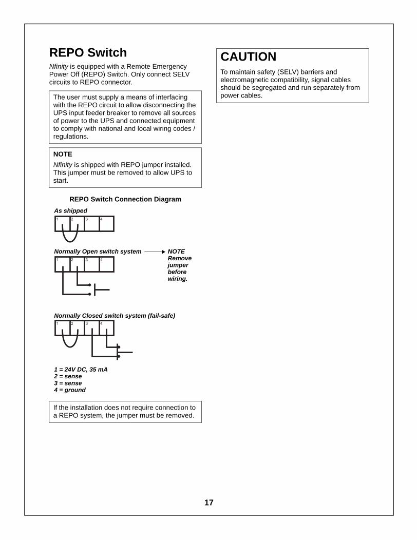
REPO SwitchNfinity is equipped with a Remote EmergencyPower Off (REPO) Switch. Only connect SELVcircuits to REPO connector.
REPO Switch Connection Diagram
The user must supply a means of interfacingwith the REPO circuit to allow disconnecting theUPS input feeder breaker to remove all sourcesof power to the UPS and connected equipmentto comply with national and local wiring codes /regulations.
NOTE
Nfinity is shipped with REPO jumper installed.This jumper must be removed to allow UPS tostart.
If the installation does not require connection toa REPO system, the jumper must be removed.
As shipped
Normally Closed switch system (fail-safe)
Normally Open switch system
1 = 24V DC, 35 mA2 = sense3 = sense4 = ground
NOTERemovejumperbeforewiring.
CAUTIONTo maintain safety (SELV) barriers andelectromagnetic compatibility, signal cablesshould be segregated and run separately frompower cables.
17

COMMUNICATIONS
COM PortsNfinity is able to communicate through multiplecommunication ports simultaneously. Only useLiebert provided communication cards. Onlyconnect SELV circuits when connecting to anycommunication port.
Pin Assignment
COM 1 - Relay ContactsRelay contacts are available through a DB-9Fcommunications connector. Contact closureprovides the following:
The contacts are rated 48VDC, 1 amp maximumand are compatible with the MultiLink software.
COM 2 - SerialNfinity is able to communicate via Liebertproprietary protocol. The pin-out configuration ofthe DB-9 connector is:
Intellislot™ PortsThe following communication cards may be usedwith Nfinity:
• Intellislot™ SNMP cards - allows the Nfinitycommunicate intelligently with your Ethernetnetwork. The SNMP card must be installed inport 1; any additional cards can be added inconsecutive ports.
• Intellislot™ MultiPort4 cards - allows up tofour client computer systems tosimultaneously monitor the status of Nfinity.
• Intellislot™ Relay Contacts cards - providescontact closures for remote monitoring ofalarm conditions; On Battery, On Bypass, LowBattery, Summary Alarm, UPS Fault and OnUPS signals. It will integrate with AS400computers (additional cable required) andother monitoring systems.
Pin Assignment
1 Low Battery (normally open)
4 UPS shutdown in battery mode(5-12 VDC for 1.5 sec)
5 Common
7 Low Battery (common)
8 On Battery (common)
9 On Battery (normally open)
Pin Assignment
2 Transmit Data
3 Receive Data
5 Common
5 4 3 2 1
6789
18

Operating InstructionsControls And Indicators
Operating ProceduresMain Menu
19

CONTROLS AND INDICATORS
Display ControlsThe User Interface Module informs you of the status of the UPS and lets you configure the UPS to yourown needs or preferences.
The module consists of a series of Status LEDs, an LCD window (four lines of 20 characters each) andbuttons for navigation, as displayed below.
ButtonsRefer to the legend below to properly navigate theNfinity User Interface.
Fault/Warning and Status LEDsRefer to the legend below to indicate occurrencewhen an LED is lit.
ESC
!
LCD Window
StandbyButton
AlarmSilenceButton
Fault/Warning LEDStatus LEDs
Navigation Buttons
- Navigates cursor on display menus
- Returns to previous display screen
- Selects displayed information
- Enables / disables output power
- Mutes the audible alarm
Up
Down
Escape
Enter
Standby
AlarmSilence
On Bypass - The Bypass is supplying the power.
Solid - A UPS fault condition has occurred.
Fault/Warning
AC Input - AC Mains is available.
Inverter On - The inverter is supplying the power.
On Battery - Battery is supplying power to the inverter.
AC Output - Power is available to supply the load.
Flashing - A Warning has occurred. Consult event log.
20

•
LED Off
UPS is On, AC Mains is Good and Output is On(Normal Operation)
UPS is On, AC Mains is Good and Output is Off
UPS is On, AC Mains is Bad and Output is Off(On Battery Operation)
UPS is in Bypass Operation(Manual or Automatic)
UPS is in Manual Bypass Operation with ACMains Out of Bypass Operation Range
Shutdown Due to End of Discharge
LED On
LED Flashing
Status LED Modes
UPS is Off or Initializing
UPS is On, AC Mains is Bad and Output is On(On Battery Operation)
21

Navigating the MenuIn order to review or change any settings on theUPS, it must be navigated using the buttons seenon the previous page. Because some menuscontain more than four rows of information, youmay see an arrow on the display pointing up ordown (as shown below) — indicating to scrollusing the or buttons.
If you are scrolling through any of the Main Menus,items will scroll one line at a time with the menuheading on the top line.
Pressing once reveals:
Note that the arrows on the screen indicate thatthe user can scroll up or down to reveal moreinformation.
UPS StatusPresent LoadRedundant StatusBattery Status >
UPS StatusRedundant StatusBattery StatusVoltage/Amps/kVA >
>
22

OPERATING PROCEDURES
Start-Up and InitializationFollow these steps to start up the UPS.
1. Ensure the manual bypass switch (SW1) is inUPS position. Close Input Circuit Breaker(CB1) and close the Control Enable Switch(SW2). You should see the following on theLCD window:
2. Press button.
3. Press to access the Main Menu.
Shutting Down the UPSUse the following procedure to power down the UPS.
1. Press to disable power from theconnected equipment.
2. Verify request to disable the output bypressing .
3. Turn off the Enable Switch (SW2). Open theInput Circuit Breaker (CB1).
Manual Transfer to BypassIn the event of a UPS overload or failure, the UPSwill transfer to bypass via its automatic bypassswitch. It is possible for the user to manuallytransfer the UPS to bypass by operating themanual bypass switch located behind the lowestfront cover to the bypass position.Follow the on-screen instructions.
It should be noted that once is pressed, thebypass alarm will annunciate and cannot becanceled until the manual bypass switch is operated.
It should be noted that the load is not protectedfrom AC Mains interruptions when in bypass mode.To transfer the UPS from bypass to normal mode,simply operate the manual bypass switch back tothe UPS position.On return from bypass, the following screen will bedisplayed.
UPS InitializingPlease wait...
Press to Enable UPS Output.
On Mains/UtilityOutput kVA = xx.xBattery Minutes yyyPress for menu
Transfer to BypassPress for bypassPress ESC to cancel
Main MenuUPS StatusUPS ConfigurationDisplay Date/TimeEvent LogAlarm Log
>Transfer to BypassModule ReplacementTools
Assert manual bypass
ManualBypassSwitch(SW1)
UPS On
Bypass
UPS on manual bypass
No active alarmsSee Event Log
23

MAIN MENU
After initialization, the button will take you to the Main Menu. From here you may check on the status ofthe UPS, review the event and alarm log, configure your UPS, and even receive instructions on replacingmodules. The Main Menu is divided into eight sub-menus as shown below:
Use the and buttons to select the desired menu item and press to access the appropriatesubmenu.
UPS Status
UPS StatusUPS StatusPresent LoadRedundant StatusBattery StatusVolts/Amps/kVA3 phase input dataUPS frequencyUPS informationModule information
Module Replacement
Module ReplacementCtrl w/ RedundantCtrl w/o RedundantPower w/ RedundantPower w/o RedundantBattery Module
Event Log
Event# xxx/xxx xx
event message event messageDD/MMM/YYYY HH:MM:SS
Main Menu
>UPS StatusUPS ConfigurationDisplay Date/TimeEvent LogAlarm LogTransfer to BypassModule ReplacementTools
UPS Configuration
UPS ConfigurationReview SettingsChange SettingsService Mode
Transfer to Bypass
Press for bypassPress ESC to cancel
Display Date/Time
Date/Timexx/xx/xxxx xx:xx:xxmm/dd/yyyy hh:mm:ss
Tools
ToolsUPS testClear failures
Alarm Log
Alarm Log Message
24

UPS Status ScreenFrom the Main Menu the user may select UPS Status and press . Once at the UPS Status Screen, theuser may access any information on the present condition of the UPS. Note the chart below whenreviewing the UPS. Any underlined text indicates measured parameters.
UPS StatusUPS StatusPresent LoadRedundant StatusBattery StatusVolts/Amps/kVA3 phase input dataUPS frequencyUPS informationModule information
Main Menu>UPS StatusUPS ConfigurationDisplay Date/TimeEvent LogAlarm LogTransfer to BypassModule ReplacementTools
Redundant StatusRedundant StatusPMs Installed xxPM:N+1 redundantSC:redundant/(non-redundant
Battery StatusBattery StatusVoltage (VDC) xxxCapacity % xxx Status: chargingBMs Installed xxExt batt present No.Discharge count: xxxxBatt Usage: Hr xxxx.x
Volts/Amps/kVAInput Output--- VAC xxx VAC--- A xxx A--- kVA xx.x kVA
3 Phase Input Data(V) (A)
Input A xxx xxxInput B xxx xxxInput C xxx xxx.
UPS FrequencyUPS Frequency
Input Hz=xx.xOutput Hz=xx.x
UPS InformationUPS Information
UPS ID: xxxxxxxxxxxxxxxxxxxxxxxxxxxxxxx
Module InformationMain ControlS/N: xxxxxxxxxxxxxxxFW ver: xxxx
Redundant ControlS/N: xxxxxxxxxxxxxxxFW ver: xxxx
User InterfaceS/N: xxxxxxxxxxxxxxxFW ver: xxxx
Power ModuleS/N: xxxxxxxxxxxxxxxFW ver: xxxx
Battery ModuleS/N: xxxxxxxxxxxxxxxFW ver: xxxx
Present LoadOn Mains/UtilityOutput: kVA xx.xOutput: kW xx.xOutput: pf xx.x
25

UPS Configuration Screen - Review Settings MenuFollow this procedure to review your UPS configuration settings. Starting at the Main Menu, select UPSConfiguration and press . Next, select Review Settings and press . Any underlined text indicatesfactory default values.
UPS ConfigurationUPS Configuration>Review SettingsChange SettingsService Mode
Main MenuUPS Status
>UPS ConfigurationDisplay Date/TimeEvent LogAlarm LogTransfer to BypassModule ReplacementTools
Frequency SettingsFrequency SettingsFrequency Hz: 50Sync Range Hz: +/- 5.0Slew Range Hz/S: 3.0
Review SettingsVoltageFrequencyBatteryAlarmsService ContactAuto RestartUPS Shutdown DelayRemote ShutdownExternal BatteryBypass Alarm ModeIntelli-Battery CabAir Filter Reminder
Battery SettingsBattery SettingsTest intrvl weeks: 2on Wed 06:00Low Batt Warn min 02
Alarm SettingsAlarm SettingsRedundant Alarm: Enabled/DisabledMax Load: xx.x/(Disabled
Service ContactService ContactLiebert Corporation
WWW.LIEBERT.COM
Auto RestartMode: Enable/DisableBatt % 25%Delay 10
Voltage SettingsVoltage Settings Input 230 LNE
Remote ShutdownRemote comm shutdownMode: Enable
External BatteryExternal Battery ConfigAmp.Hr 0000Charge (A)00.0
Bypass Alarm ModeBypass Alarm ModeMode: Enable
Intelli-Battery CabIntelli-Batteries
0
Air Filter ReminderAir Filter ReminderMode:xx weeks/Disabled
UPS Shutdown DelayUPS Shutdown Delay120 seconds
26

UPS Configuration Screen - Change Settings MenuStarting at the Main Menu, select UPS Configuration and press . Next, select Change Settings andpress . Here one may configure Nfinity from a large variety of selections. Items with an asterisk (*) andthose that are underlined are the selected settings.
Input Voltage L-N: Select the required inputvoltage setting.
Frequency Settings: Sets the input and outputoperating frequency of the system.
Frequency Sync Range: Sets the window towhich the system synchronizes to the input supply.
Frequency Slew Rate: Sets the rate of change offrequency through the sync range window.
Set Password: Set a Password to preventunauthorized users from changing theconfiguration of the Nfinity. It can be up to 7characters in length. Once set, the password willbe required to change the configuration.
Change SettingsChange SettingsInput VoltageFrequencyFreq Sync RangeFreq Slew RateSet PasswordAuto Battery TestLow Battery WarningAuto RestartUser SettingsSet Time/DateMax Load AlarmUPS Shutdown DelayRedund't Alarm SetService ContactRemote ShutdownExternal BatteryBypass Alarm ModeIntelli-Battery CabAir Filter ReminderFactory Defaults
Main MenuUPS Status
>UPS ConfigurationDisplay Date/TimeEvent LogAlarm LogTransfer to BypassModule ReplacementTools
UPS ConfigurationUPS ConfigurationReview Settings
>Change SettingsService Mode
Input Voltage230 LNE
*240 LNE
Transformer ModelsInput Voltage230 LNE220 LNE
*240 LNE
Frequency Output*50 Hz60 Hz
Frequency Sync Range±0.5 Hz±1.0 Hz±2.0 Hz±3.0 Hz±4.0 Hz
*±5.0 Hz
WARNINGIf the password is lost, call Liebert TechnicalSupport.
Frequency Slew Rate0.5 Hz/S1.0 Hz/S2.0 Hz/S3.0 Hz/S4.0 Hz/S
*5.0 Hz/S
Set Password[xxxxxxx]
27

Change Settings Menu, cont’dAuto Battery Test: Configure when and how oftenthe Nfinity’s automatic battery test will run. Thistest is designed to ensure Battery system integrityand provide early warning of problems.
Low Battery Warning: Notifies user how muchruntime is available; can be set from 1 to 30 minutes.
Auto Restart: Automatically restarts once bothdelay parameters (battery capacity percentageand countdown timer) are met.
User Settings: From here one can enter the UPSID, adjust the contrast of the user interface LCD orselect the appropriate language.
Set Date/Time: Allows user to enable/disable DST(Daylight Savings Time), change the Day, Dateand Time setting on Nfinity. When enabled, thetime will automatically adjust to Daylight Savings.
Auto Battery TestIntervalStart Day Start Time
IntervalBattery Test Intrvl1 week
*2 weeks3 weeks4 weeks 6 weeks Disabled
Start DayBattery Test WeekdayWED
Start TimeBattery Test Time06:00
Low Battery Warning02 Minutes
Auto RestartModeAuto Restart Batt % Auto Restart Delay
Auto Restart ModeAuto Restart Mode*EnableDisable
Auto Restart Batt %Auto Restart Batt % 0%10%
*25%40%60%80%
Auto Restart DelayAuto Restart Delayin 10 secondincrements,
x0 seconds
User SettingsSet UPS IDScreen ContrastDisplay Language
Set UPS IDSet UPS IDxxxxxxxxxxxxxxxxxxxxxxxxxxxxxx
Display LanguageDisplay LanguageEnglishFrancaisItalianoDeutschEspanol
Screen ContrastScreen Contrast
Press to Increase
Press to Decrease
Set Time/DateDST ModeSet Time/Date
DST ModeDST Mode*EnabledDisabled
Set Date/TimeDate/Time
MM/DD/YYYY HH:MM:SS
28

Change Settings Menu, cont’dMax Load Alarm Set: Allows an alarm to setwhen Nfinity’s load reaches a specific level.
UPS Shutdown Delay: Delays UPS shutdown forspecified amount of time after receiving shutdowncommand via communications (serial or SNMP).
Redundant Alarm Set: Sets Alarm to notify userwhen redundancy is no longer available.
Service Contact: Set a contact for the user toreach if problems occur.
Remote Shutdown: Enables / Disables theRemote Communications Shutdown.
If you are using MultiLink™ software, thisparameter should be enabled in order for the UPSoutput to be turned off once the operating systemhas been shut down.
External Battery: Sets total amp-hour for externalbatteries to provide a more accurate run timeremaining value on the LCD and throughcommunications.
Enter the following when using the ExternalBattery Cabinets with Chargers.
(P/N: PB10SLF105WC-CE)
Bypass Alarm Mode: Allows the user to enable/disable alarm, indicating that the bypass is notqualified.
Intelli-Battery Cab: Allows the user to enter thequantity of intelligent battery cabinets installed.
Max Load Alarm Mode Set Threshold
Alarm ModeMax Load Alarm ModeEnable
*Disable
Set ThresholdMax Load Alarm SetThreshold kVA = xx.x
UPS Shutdown Delayxxx Seconds
Redund PowerAlarm Set N+1 redundant
*Disable
Service Contact Company Contact Number
Company Name
LIEBERT CORPORATION
Contact Number
WWW.LIEBERT.COM
# of Cabinets AH Value ChargeCurrent
1 0091 7.0
2 0182 14.03 0273 21.04 0364 28.0
5 0455 35.06 0546 42.0
Remote comms Shutdn*EnableDisable
External BatteryAmp-hour
>Charge Current
External Batt ConfigEnter charge current
00.0
External Batt ConfigEnter total amp-hour
0000
Bypass Alarm Mode*EnableDisable
Enter Intelli-Battery cabinet count
x
29

Change Settings Menu, cont’dAir Filter Reminder: On transformer models only,allows the user to set a warning reminder to checkthe air filters.
Factory Defaults: Allows the user to reset allsettings to be the same as when the UPS wasshipped from the factory.
Air Filter Reminder2 weeks4 weeks10 weeks26 weeks52 weeks
*Disable
Load Factory DefaultAre you sure?Press for yesPress ESC for no
30

UPS Configuration Screen - Service Mode MenuService Mode contains site identification information about the UPS system. The data is entered by LiebertGlobal Services (LGS). To view the data, go to the Main Menu, select UPS Configuration and press .Next, select Service Mode and press .
Set Site ID: Press to return to the ServiceMode menu. Scroll to Set Site ID and press todisplay the screen shown below.
Set Tag Number: Press to return to theService Mode menu. Scroll to Set Tag Number andpress to display the screen shown below.
Display Date/TimeThis feature shows the current date and time. At the Main Menu, select UPS Configuration and press .Next, select Display Date/Time and press
Main MenuUPS Status
>UPS ConfigurationDisplay Date/TimeEvent LogAlarm LogTransfer to BypassModule ReplacementTools
UPS ConfigurationUPS ConfigurationReview SettingsChange Settings
>Service Mode
Service ModeService Mode>Set Site IDSet Tag Number
ESC
Set Site ID-
Service ModeService Mode>Set Site IDSet Tag Number
ESC
Service ModeService ModeSet Site ID
>Set Tag Number
Set Tag Number-
Display Date/TimeDate/Timexx/xx/xxxx xx:xx:xxmm/dd/yyyy hh:mm:ss
Main MenuUPS StatusUPS Configuration
>Display Date/TimeEvent LogAlarm LogTransfer to BypassModule ReplacementTools
31

Event LogAccessing the Event Log enables the user to scrollthrough the Nfinity’s past 255 occurrences. Toopen the Event Log, start at the Main Menu, selectEvent Log and press .
Press the and buttons to scroll through theNfinity’s Event Log in chronological order. TheEvent Log contains the following information.
The typical event log screen will display the eventnumber and reference code on the first line. Thepurpose of this code is to assist factory trainedservice personnel in troubleshooting. Please makea note of the code number when contactingtechnical support. The second line contains theevent description. The third line will have eithermore detail about the event, a serial numberindicating as to which module the event occurred,or be left blank. The last line will show the date andtime the event occurred.
Press to go back to the Main Menu.
When an event or alarm occurs, the User InterfaceLCD will display the last message regardless ofthe default screen. See Alarm Messages onpage 35 for a list of events and alarms andpossible solutions. If you are unsure of thecorrective action to take, contact a Liebertrepresentative at the number listed on the back ofthis manual.
Alarm LogAlarms affecting the Nfinity can be viewed at theAlarm Log screen. To access the screen, go to theMain Menu, select Event Log and press .
When an alarm sounds, the User Interface LCDwill display a general explanation as to what thealarm is indicating. To view these messages inchronological order, press the and buttons.
• The first line of a typical alarm log screen willdisplay the reason for the alarm occurrence.
• The second line will give a more specific detailof the occurrence (i.e., module serial number).
Press to go back to the Main Menu.
Transfer to BypassIn the event of a UPS overload or failure, the UPSwill transfer to bypass via its automatic bypassswitch. The user can manually transfer the UPS tobypass if needed. For information, see ManualTransfer to Bypass on page 22.
Main MenuUPS StatusUPS ConfigurationDisplay Date/Time
>Event LogAlarm LogTransfer to BypassModule ReplacementTools
Event Log
Event# xxx/xxx xx
event message event messageDD/MMM/YYYY HH:MM:SS
Event # 031/255 04Power module removedS/N:0012200001002G119 MAY 2000 16:54:27
Event Detail orSerial Number
Date of Event Time of Event
Description
Event Number Reference Code
ESC
Main MenuUPS StatusUPS ConfigurationDisplay Date/TimeEvent Log
>Alarm LogTransfer to BypassModule ReplacementTools
Alarm Log
Alarm Log Message
ESC
32

Module ReplacementThe user interface also supplies instructions for removing and replacing modules. From the Main Menu,access the module replacement screen and select the type of module. Refer to the screens below:
For more details on module replacement, consult Troubleshooting on page 34.
Module ReplacementModule Replacement>Ctrl w RedundantCtrl w/o RedundantPwr w RedundantPwr w/o RedundantBattery Module
Main MenuUPS StatusUPS ConfigurationDisplay Date/TimeEvent LogAlarm LogTransfer to Bypass
>Module ReplacementTools
Control Module w RedundantCntl Mod Replacement1. Lift off display panel and place on top of UPS2. Locate amber LED3. Open lever4. Loosen fastener5. Replace module6. Tighten fastener7. Close lever8. Replace display
Power Module w RedundantPwr Mod Replacement1. Remove all front bezels2. Locate amber LED3. Open lever4. Loosen fastener5. Replace module6. Tighten fastener7. Close lever8. Replace all bezels
Control Module w/o RedundantCntl Mod Replacement1. Remove bottom bezel and place UPS in bypass2. Lift off display panel and place on top of UPS3. Locate amber LED4. Open lever5. Loosen fastener6. Replace module7. Tighten fastener8. Close lever9. Wait for amber LED to stop flashing10.Replace display11.Switch bypass to return to UPS operation12.Replace bezel
Battery ModuleBattery Module1. Remove all front bezels2. Locate amber LED3. Loosen fastener4. Replace module5. Tighten fastener6. Replace all bezels
Power Module w/o RedundantPwr Mod Replacement1. Remove bottom bezel and place UPS in bypass2. Remove remaining front bezels3. Locate amber LED4. Open lever5. Loosen fastener6. Replace module7. Tighten fastener8. Close lever9. Wait for amber LED to stop flashing10. Switch bypass to return to UPS operation11.Replace all bezels
33

ToolsThe Tools option allows the user to carry out certain tests and clear failures. From the Main Menu, selectTools and press .
UPS Test: Allows the user to test the LEDs, LCD,Batteries, or Alarm.
Clear Failures: Allows the user to reset the UPSafter a Battery Module failure alarm.
ToolsTools>UPS testClear failures
Main MenuUPS StatusUPS ConfigurationDisplay Date/TimeEvent LogAlarm LogTransfer to BypassModule Replacement
>Tools
UPSTestLEDLCDBattery
Tools>UPS testClear failures
ToolsUPS test
>Clear failures
Clear FailuresClear batt failures
Clear batt failuresPress for yesPress ESC for no
34

TroubleshootingAlarm Messages
Module LED IndicationModule Replacement
35

ALARM MESSAGES
In the event of an alarm, the User Interface LCD will display the last message regardless of the defaultscreen. A list of possible alarm messages is displayed below. If you encounter one of these or other alarmmessages and are unsure of the corrective action to take, please contact a qualified Liebert representativeat the number listed on the back of this manual.
Alarm Message Cause Action
UPS Shutdown - End ofDischarge
Shutdown because there is notenough battery power left to sup-port the load.
Wait for return of AC Mains
Battery Module Fail A Battery Module has failedRefer to Module LED indication section for correc-tive action
Number of Battery Mod-ules changed
The number of Battery Modulesin the system has changed
No action
Number of Power Mod-ules changed
The number of Power Modules inthe system has changed
No action
Power Module Fail A Power Module has failedMatch module serial number to serial number inAlarm Log or Event Log, replace module
Active control fail An ASC failureMatch module serial number to serial number inAlarm Log or Event Log, replace module
Passive control fail A PSC failureMatch module serial number to serial number inAlarm Log or Event Log, replace module
Power Module N+1Redundancy Alarm
The UPS is no longer redundantInsert more Power Modules or replace faulty PowerModule to regain redundancy
Output Off - OutputShort Circuit
There was a short circuit on theoutput.
Investigate fault on load side of UPS
Low Battery Warning Battery power is lowNo action, Set point for low battery time remaininghas been reached. Allow batteries time to recharge
UPS On AutomaticBypass
UPS switched to auto bypass forvarious reasons.
Determine reason from Alarm Log or Event Historylog why UPS is on Bypass
UPS Output OverloadThe load exceeds the maximumload capacity of the active PowerModules.
Reduce the amount of connected load or addPower Modules
UPS On BatteryThe unit is supporting the loadfrom its batteries.
Wait for return of AC Mains
Bypass source not qual-ified
The unit will not transfer to auto-matic bypass, instead the loadwill be dropped
Investigate AC Mains supply
Transformer Fan FailureThere is a transformer in the unit,and at least one of the fans is notrunning
Investigate fans
Transformer tempera-ture warning
The Transformer is slightly overtemperature.
Investigate possible airflow problem
Transformer tempera-ture alarm
The Transformer is greatly overtemperature.
Investigate immediately
Input Voltage SettingError
The input voltage configurationand bypass jumper settings donot match.
Ensure that the bypass voltage matches the inputvoltage and that the input voltage configurationmatches the bypass jumper setting
36

Power Module Warning Something abnormal occurringMatch module serial number to serial number inAlarm Log or Event Log, Contact qualified assis-tance
Battery Module Warn Something abnormal occurringMatch module serial number to serial number inAlarm Log or Event Log, Contact qualified assis-tance
Main Control Warning Something abnormal occurringMatch module serial number to serial number inAlarm Log or Event Log; contact qualified assis-tance
Main Control Failure Main Control Module has failedRefer to Module LED indication section for correc-tive action
Redund. Control Warn Something abnormal occurringMatch module serial number to serial number inAlarm Log or Event Log, Contact qualified assis-tance
Redund. Control FailRedundant Control Module hasfailed
Refer to Module LED indication section for correc-tive action
Output exceeds maxload setting
Max load alarm is enabled, andthe load is greater then the valueset
None, if additional load is not added
Switch To ManualBypass
The switch on the only good SChas been lifted. Informs user thatthey should switch to bypass toavoid dropping the load when thepull the SC out.
Close manual bypass switch.
Battery Module NotReady
A Battery Module is not readyand should be blinking it's yellowLED.
Ensure module is fully seated and locked intoplace. Refer to Module LED indication section forcorrective action.
Power Module NotReady
A Power Module is not ready andshould be blinking it's yellowLED.
Ensure module is fully seated and locked into placeand lock lever is down. Refer to Module LED indi-cation section for corrective action.
Load Exceeds BatteryModule Capacity
Occurs when there are no exter-nal, extended, or normal BatteryModules in the system, or whenthe load is too great for the activeBattery Modules to support
Check the number of Battery Modules installed andthe power required by the connected load.
Bypass source not qual-ified
The AC Mains is out of range, unitwill not go to automatic bypass.
Check AC Mains supply.
UPS switched frombypass to inverter
The UPS switched from auto-matic bypass to normal opera-tion.
None
UPS on manual bypassThe user has put the unit onmanual bypass with the breakeron the bottom front of the unit.
None
CAN CommunicationsTimeout
A module in the system hastimed out
See Event log
Turn SW2 off beforeremoving
Bypass source is not qualified orthe output is off, and lever on thelast good SC has been lifted.This warning is to shut down theunit with the rear rocker switchbefore pulling out the SC.
Switch SW2 off
Alarm Message Cause Action
37

Load exceeds framelimit
Load is greater then the ratedframe limit.
Remove some of the connected load
Battery Card Warning Something abnormal occurring Contact qualified assistance
Battery Card Failure An Intelli-Battery Card has failed Replace faulty card
Configuration error! Re-enter settings
The configurations in the UI andASC do not match.
To clear, review or change configuration settings
Assert manual bypass
If the user does a switch to man-ual bypass from the UI they willbe prompted to physically switchto manual bypass with this alarm.
Close manual bypass switch
Output must be on
The UPS's output must be onprior to selecting bypass from theUI. This alarm will be generated ifthe customer requests bypassfrom the UI when the output isnot on. [NM UPS General Warn-ing]
Push UPS output button
External Battery Mod-ule Warning
Something abnormal occurringwith the external battery system
Contact qualified assistance
External Battery Mod-ule Failure
There is a failed battery in theexternal battery system
Contact qualified assistance
System Is Not ReadyPlease Wait
The UPS's output could not beturned on because the systeminitialization is not yet complete.
Wait 30 seconds for alarm to clear
Power Module Is NotReady - Please Wait
The UPS's output could not beturned on because the PowerModule initialization is not yetcomplete.
Wait 30 seconds for alarm to clear
Please Review Or SetConfiguration
The configurations in the UI andASC do not match.
To clear either review or change configuration set-tings
Not Available Due ToSystem Failure
The UPS's output could not beturned on because there is a sys-tem failure.
Wait 30 seconds for alarm to clear
Battery module commu-nication failed
CAN communication betweenthe SC and a Battery Modulehave failed.
Contact qualified assistance
Power module commu-nication failed
CAN communication betweenthe SC and a Power Modulehave failed.
Contact qualified assistance
UI is not compatible withthis system
The User Interface is not com-patible with the current SystemControl.
Contact qualified assistance
Reminder alarm - Checkair filter
Fan Filter alarm is enabled andtime interval has passed
Make sure transformer air filter is free of dust
Abnormal battery volt-age
Abnormally low battery bus volt-age
Contact qualified assistance
Comm failure, switch tomanual bypass
The User Interface has detecteda can bus off
Contact qualified assistance
Internal comms failureThe User Interface has detecteda can bus off
Contact qualified assistance
Alarm Message Cause Action
38

MODULE LED INDICATION
On every Battery, Power or Control Module are two LEDs to help inform the user of the module status.Refer to the chart below:
Status LED(Green)
Fault LED(Amber) Module Status
OFF OFF Module not inserted into frame.System is OFF.
OFF ON Module is initializing (max 30 seconds*).
FLASHING OFF Normal Operation
FLASHING FLASHING Module is in start-up qualification mode, or module warning. **
FLASHING ON Module failed, is off-line and module control is functioning.
OFF FLASHING
Abnormal operation, re-insert module.If this persists, contact qualified assistance.
ON OFF
ON ON
ON FLASHING
* If this persists for more than 30 seconds, check to verify the lever is in the down position; otherwise the module isfaulty.
** If both Green and Amber LEDs are flashing for more than 30 seconds, then re-insert module.
Status LEDFault LED
Control Module
Status LEDFault LED
Status LEDFault LED
Battery Module
Power Module
39

MODULE REPLACEMENT
Follow the instructions below when replacing acontrol, battery, or power module, or when addingmodules to the system. To order additionalmodules, contact your Liebert representative.
Removing Modules1. Remove bezel cover of appropriate module.
When replacing a Power or Battery Module,verify the faulty module by confirming theamber LED is lit.
2. If removing a Control or Power Module with noredundant modules, switch UPS to manualbypass. Switch SW2 off (0) to minimize risk ofdamage to modules.
3. Pull out and lift the lever if replacing a Controlor Power Module, then turn fastenercounterclockwise until it is loosened.
4. Start to pull out module. About 2/3 out it willstop. Slide module away from the centre of theUPS.
CAUTION: Battery Modules are heavy—30 kg (66 lb). Make sure to use two people whenremoving a Battery Module. Continue to pull untilmodule is removed (seen at right).
5. Dispose of module in an environmentallyresponsible way that complies with localcodes / regulations or return to Liebert forproper disposal.
Note: Battery Modules may contain shippingscrews. These screws may be removed anddiscarded.
WARNINGPOTENTIAL TIP HAZARDInstall all modules starting from bottomto top bays. For module removal startfrom top to bottom bays. Do notremove more than one module at atime. Failure to do so may cause unit totip over and cause serious injury.
40

Replacing Modules
1. Lift module to appropriate bay, resting end ofmodule on bay shelf. Use caution not to restthe module on the lower bezel cover.
2. Push module into bay. Once halfway in, slidemodule sideways toward the centre of theUPS. Continue pushing module until fullyinserted.
3. Press and turn fastener clockwise until locked.If replacing a Control or Power Module, presslever down.
4. Wait about 30 seconds as the moduleperforms a start-up test and synchronizes withthe other modules. Both the amber and greenLEDs should be flashing. A green flashingLED will then confirm the module is properlyconnected.
5. If UPS was placed in bypass manually,transfer back to UPS operation.
6. Replace bezels.
Replacing the UserInterface
1. Lift off user interface and set it on top of theUPS frame.
2. The attached cable will be connected to anIntellislot card, found in a port between thecontrol modules.
3. Disconnect the cable from the Intellislot card.4. Install the new Intellislot card in the UPS.5. Plug the new user interface cable into the
Intellislot card.6. Set replacement User Interface into proper
position.
Note: Power Modules must be installed in a bayin the top half of the Nfinity frame. BatteryModules can be installed in any bay of the UPSframe.
Note: When replacing the Control Module,record user configuration data before removing.Re-verify the configuration settings after thenew Control Module is installed.
41

42

MaintenanceProper Care
Scheduled MaintenanceReplacing Fan Filters
43

MAINTENANCE
Proper CareKeeping your Liebert Nfinity UPS operatingproperly is imperative to optimal performance andlife of the unit. It is recommended that a certifiedtechnician perform preventive and correctivemaintenance. Liebert Global Services (LGS) isdedicated to ensuring the highest level ofperformance and unmatched support for yourNfinity UPS. Contact an LGS representative forservices to guarantee maximum reliability andsystem availability.
Scheduled MaintenanceIt is recommended the following maintenance isperformed at least monthly:
• Clean unit• Clean / replace filters• Verify proper airflow
It is recommended the following maintenance isperformed annually:
• Verify all power modules are operatingproperly.
• Verify all battery modules are operatingproperly.
• Verify redundancy (if applicable).
Replacing Fan Filters(Transformer Models Only)
Nfinity’s intake fans contain filters that will need tobe replaced / cleaned periodically, depending onthe surrounding environment. Check by removingthe bottom bezel and noting the condition of thetwo filters. If filters are dirty, replace them byremoving the plastic cover over the filter frame andinserting a new filter in its place. Use caution whenreplacing filters when fans are running.
The fan filters are washable and can be reused. Towash filters, place them under a running faucet(with the dirt side down) to remove dirt and dust.Blot dry with a towel and allow air-drying beforereusing.
Fan Filters
44

ReferenceSpecifications
Approximate Battery Run Times
45

SPECIFICATIONS
•General & Environmental Units Configuration
Unit RatingkVA 4 8 12 16 20
kW 2.8 5.6 8.4 11.2 14.0Conducted and Radiated EMC Compliance EN 50091-2 Class ACompliant Safety Standards EN50091-1-1, EN60950, CE, Low Voltage Directive
Compliant Immunity Standards EN61000-4-2,3,4,5,6
Mechanical Units 12 Bay
Dimensions:Width
mm (in)508 (20)
Depth 711 (28)Height 1346 (53)
Environmental Units
Operating Temperature (max) C (F) 0° - 40° (32° - 104°)
Relative Humidity % 0-95% non-condensingMaximum operating altitude M (Ft) 3,000 (10,000)
Nominal heat dissipationW
(BTUH/hr)311
(1062)622
(2124)933
(3186)1244
(4248)1265
(4320)Acoustic noise level dBA <62 @ 1 metre (39 in)
Input Data Units
Nominal input voltage VAC 380/400/415 (380 V has output transformer)
Power factor Cos Ø >.80Input frequency (nominal) Hz 50Input frequency range Hz 40-70
Battery Module Units
Number of lead acid batteries 10
Number of battery cells 60Battery capacity A/hr 9
Autonomy time (full load) minutes6 (with an equal number of Battery & PowerModules in a non-redundant configuration)
Maximum charge current (full load) A 3
Nominal Voltage VDC 120Recharge Time Hrs <6 (to 90% capacity)
Output Data Units
Output voltage VAC 220/230/240 (220V requires output transformer)Voltage regulation % ±3
Voltage stability (100% step load) % ±7Recovery time msec 96
Voltage distortion: %<3 THD, linear load
<7 THD, non-linear loadOutput frequency Hz 50Efficiency at 100% load % 91
Efficiency at 100% load (transformer models) % 89
Output overload capability %
>100% - 110% operates indefinitely111% - 150% operates for 8 sec
151% - 200% operates for 0.25 sec>201% operates for 2 cycles
46

APPROXIMATE BATTERY RUN TIMES
12 Bay Frame, Internal and External (minutes)LoadVA
LoadWatts
Quantity of Battery Modules Quantity of External Battery Cabinets w/Charger
1 2 3 4 5 6 7 8 9 10 11 1 2 3 4 5 6
20,000 14,000 - - - - 7 9 12 - - - - 17 46 78 119 158 19919,500 13,650 - - - - 7 9 12 - - - - 18 48 81 123 163 20519,000 13,300 - - - - 7 9 13 - - - - 19 49 84 127 169 21218,500 12,950 - - - - 8 11 13 - - - - 20 51 87 131 174 21918,000 12,600 - - - - 8 12 14 - - - - 20 53 90 136 180 22617,500 12,250 - - - - 8 12 14 - - - - 21 55 93 141 187 23517,000 11,900 - - - - 9 13 15 - - - - 22 57 97 146 194 24316,500 11,550 - - - - 9 13 15 - - - - 23 59 101 152 201 25316,000 11,200 - - - 7 9 13 17 19 - - - 24 62 106 157 209 26215,500 10,850 - - - 7 10 13 17 20 - - - 25 64 112 164 217 27215,000 10,500 - - - 7 11 14 18 21 - - - 27 67 118 171 226 28414,500 10,150 - - - 8 12 15 19 22 - - - 28 70 124 178 236 29614,000 9,800 - - - 8 13 16 20 23 - - - 29 73 129 186 246 30913,500 9,450 - - - 8 13 16 20 24 - - - 31 77 135 195 258 32313,000 9,100 - - - 9 13 17 21 25 - - - 32 81 142 205 270 33812,500 8,750 - - - 10 14 18 22 26 - - - 34 85 149 215 283 35512,000 8,400 - - 7 12 16 20 24 28 32 - - 36 90 157 226 298 37311,500 8,050 - - 7 12 17 21 25 29 34 - - 38 95 166 239 314 39211,000 7,700 - - 7 12 17 21 26 30 35 - - 40 101 176 252 332 41310,500 7,350 - - 8 14 18 23 28 32 37 - - 43 109 186 267 352 43510,000 7,000 - - 9 15 19 24 29 34 38 - - 46 118 198 283 396 4599,500 6,650 - - 10 15 21 26 30 36 41 - - 49 126 211 302 396 4869,000 6,300 - - 11 16 22 28 33 38 44 - - 53 135 226 323 422 5178,500 5,950 - - 12 17 23 29 35 40 46 - - 57 146 243 347 449 5518,000 5,600 - 7 13 19 25 31 37 43 49 55 - 62 157 262 373 480 5897,500 5,250 - 8 14 21 28 34 40 47 53 59 - 67 171 283 402 517 6307,000 4,900 - 8 16 23 30 36 43 50 57 64 - 73 186 309 435 558 6786,500 4,550 - 9 17 24 32 40 47 55 62 69 - 81 205 339 473 605 7346,000 4,200 - 11 19 24 36 43 51 60 68 76 - 90 226 373 517 659 7985,500 3,850 - 12 21 23 39 47 56 66 74 82 - 101 252 413 569 722 8755,000 3,500 - 14 23 28 42 52 61 72 80 90 - 118 283 459 630 798 9704,500 3,150 - 15 25 37 47 57 67 78 88 98 - 135 323 516 704 891 10884,000 2,800 7 19 31 43 55 66 79 91 104 115 128 157 374 590 799 1016 12443,500 2,450 9 23 37 51 65 79 93 107 123 136 151 187 436 679 920 1177 14503,000 2,100 11 28 44 60 76 93 109 126 143 159 176 226 517 798 1090 1403 17312,500 1,750 14 33 52 71 89 109 128 147 167 185 205 283 630 970 1337 1729 21332,000 1,400 18 42 65 88 112 136 160 183 207 230 254 372 797 1240 1727 2233 27591,500 1,050 26 57 87 119 151 182 213 243 276 306 337 515 1085 1723 2400 3118 >35001,000 700 45 94 144 195 246 294 344 393 444 493 541 802 1739 2777 >3500 >3500 >3500900 630 50 105 160 216 273 327 382 436 492 547 600 893 1958 3135 >3500 >3500 >3500800 560 55 116 177 238 300 359 420 480 540 601 659 1013 2233 >3500 >3500 >3500 >3500700 490 61 128 195 263 331 396 463 529 594 661 726 1168 2593 >3500 >3500 >3500 >3500600 420 72 149 227 304 382 457 535 610 685 762 836 1416 3159 >3500 >3500 >3500 >3500500 350 82 171 258 346 433 518 606 691 777 862 947 1739 >3500 >3500 >3500 >3500 >3500
Note: Back-up times in minutes are approximate and are based on resistive loading at an ambient temperature of 25°C(77°F) under controlled conditions.Backup times for External Battery Cabinets with Chargers do not include internal battery modules. To calculate total runtime, add External Battery Cabinet run time to run time listed for your particular configuration of internal battery modules.When using an External Battery Cabinet(s), one External Battery Cable or External Battery Adapter must be ordered tomake the connection to the Nfinity UPS. Connections between multiple External Battery Cabinets are made usingcontractor-supplied wiring and conduit.
47

48


The Company Behind the Products
With over a million installations around the globe,Liebert is the world leader in computer protectionsystems. Since its founding in 1965, Liebert hasdeveloped a complete range of support andprotection systems for sensitive electronics:
• Environmental systems—close-control airconditioning from 1 to 60 tons
• Power conditioning and UPS with powerranges from 300 VA to more than 1000 kVA
• Integrated systems that provide bothenvironmental and power protection in asingle, flexible package
• Monitoring and control—from systems of anysize or location, on-site or remote
• Service and support through more than 100service centres around the world and a 24/7Customer Response Centre
While every precaution has been taken to ensurethe accuracy and completeness of this literature,Liebert Corporation assumes no responsibility anddisclaims all liability for damages resulting fromuse of this information or for any errors oromissions.
© 2002 Liebert CorporationAll rights reserved throughout the world.Specifications subject to change without notice.
® Liebert and the Liebert logo are registeredtrademarks of Liebert Corporation. All namesreferred to are trademarks or registeredtrademarks of their respective owners.
SLI-23970 EN (9/02) Rev. 2
POWER PROTECTION
Nfinity™ 3:1 Power System
USER MANUALTechnical Support
United States1050 Dearborn Drive
P.O. Box 29186Columbus, OH 43229
1-800-LIEBERT
Outside the United States+614-888-0246
UK+44 (0) 1628 403200
France+33 1 43 60 26 19
Germany+49 2166 96 49 340
Netherlands+31 475 504050
ItalyVia Leonardo Da Vinci 8
Zona Industriale Tognana35028 Piove Di Sacco (PD)
+39 049 9719 111FAX: +39 049 5841 257
Asia23F, Allied Kajima Bldg.
138 Gloucester RoadWanchai
Hong Kong+852 2 572 2201
FAX: +852 2 831 0114
Web Sitewww.liebert.com