next generation nuclear plant materials research and
TRANSCRIPT
INEEL/EXT-04-02347Revision 1
Next Generation Nuclear Plant Materials Research and Development Program Plan
September 2004
Idaho National Engineering and Environmental Laboratory Bechtel BWXT Idaho, LLC

INEEL/EXT-04-02347Revision 1
Next Generation Nuclear PlantMaterials
Research and Development Program Plan
G.O. Hayner, E.L. Shaber, R.E. Mizia, R.L. Bratton, W.K. Sowder, R.N. Wright, W.E. Windes, T.C. Totemeier, K.A. Moore
National Technical Director and Staff W.R. Corwin, Director
T.D. Burchell, J. M. Corum, J. W. Klett, R.K. Nanstad, L.L. Snead, P.L. Rittenhouse, R.W. Swindeman, D.F. Wilson, T.E. McGreevy
Other DOE Laboratory Contractors R. Jones, F. Gardner
September 2004
Idaho National Engineering and Environmental Laboratory Idaho Falls, Idaho 83415
Prepared for the U.S. Department of Energy
Assistant Secretary for Office of Nuclear Energy Under DOE Idaho Operations Office
Contract DE-AC07-99ID13727

ii
This page intentionally left blank.

iii
SIGNATURES OF APPROVAL
Originator:
______________________________________________ ________________________________
George O. Hayner Date NGNP Materials R&D Program Manager
Reviewer(s):
____________________________________________ ________________________________
Russell Jones Date Chair, NGNP Materials Review Committee
___________________________________________ ________________________________
Philip MacDonald Date NGNP Program Manager

iv
This page intentionally left blank.

v
EXECUTIVE SUMMARY
The U.S Department of Energy (DOE) has selected the Very High Temperature Reactor (VHTR) design for the Next Generation Nuclear Plant (NGNP) Project. The NGNP will demonstrate the use of nuclear power for electricity and hydrogen production without greenhouse gas emissions. The reactor design will be a graphite moderated, helium-cooled, prismatic or pebble-bed, thermal neutron spectrum reactor that will produce electricity and hydrogen in a state-of-the-art thermodynamically efficient manner. The NGNP will use very high burn-up, low-enriched uranium, TRISO-coated fuel and have a projected plant design service life of 60 years.
The VHTR concept is considered to be the nearest-term reactor design that has the capability to efficiently produce hydrogen. The plant size, reactor thermal power, and core configuration will ensure passive decay heat removal without fuel damage or radioactive material releases during accidents. The NGNP Project is envisioned to demonstrate the following:
A full-scale prototype VHTR by about 2017
High-temperature Brayton Cycle electric power production at full scale with a focus on economic performance
Nuclear-assisted production of hydrogen (with about 10% of the heat) with a focus on economic performance
By test, the exceptional safety capabilities of the advanced gas-cooled reactors.
Further, the NGNP program will:
Obtain a Nuclear Regulatory Commission (NRC) License to construct and operate the NGNP and to provide a basis for future performance based, risk-informed licensing
Support the development, testing, and prototyping of hydrogen infrastructures
The NGNP Materials Research and Development (R&D) Program is responsible for performing R&D on likely NGNP materials in support of the NGNP design, licensing, and construction activities. Based on the DOE NGNP Acquisition Strategy, the activities in this program will be closely coordinated with the materials selection, design, and construction activities of the Project Integrator (following DOE selection). The NGNP Materials R&D Program includes the following elements:
Developing a specific approach, program plan and other project management tools for managing the R&D program elements
Developing a specific work package and project execution plan for the R&D activities to be performed during each government fiscal year
Reporting the status and progress of the work based on committed deliverables and milestones
Developing collaboration in areas of materials R&D of benefit to the NGNP with countries that are a part of the Generation IV International Forum
Ensuring that the R&D work performed in support of the materials program is in conformance with established Quality Assurance and procurement requirements
vi
Establishing an interface with the Project Integrator (following DOE selection) to continue to facilitate materials R&D in support of NGNP materials selection, design, licensing, and construction activities.
The objective of the NGNP Materials R&D Program is to provide the essential materials R&D needed to support the design and licensing of the reactor and balance of plant, excluding the hydrogen plant. The materials R&D program is being initiated prior to the design effort to ensure that materials R&D activities are initiated early enough to support the design process and support the Project Integrator. The thermal, environmental, and service life conditions of the NGNP will make selection and qualification of some high-temperature materials a significant challenge; thus, new materials and approaches may be required. The following materials R&D program areas are currently addressed in the R&D program being performed or planned:
Qualification and testing of nuclear graphite and carbon fiber/carbon matrix composites for use in the NGNP. These components are essential to any VHTR design and the irradiation induced dimensional and material property changes must be properly modeled.
Development of improved high-temperature design methodologies for application toward the further development, qualification, and selection of high-temperature metallic alloys for potential application in the NGNP. Currently, the data and models are inadequate for many of the high-temperature alloys required for construction of the VHTR.
Expansion of American Society of Mechanical Engineers (ASME) Codes and American Society for Testing and Materials Standards in support of the NGNP Materials R&D Program. This work is required because of NRC licensing and construction requirements.
Development of an improved understanding of, and models for, the environmental effects and thermal aging of the metallic alloys for potential application in the NGNP. This work is needed because metallic alloys undergo property changes as a function of exposure to the high temperature, impure gas environments expected in the VHTR (i.e., we are looking at the effects of both impure gas and high temperature).
Irradiation testing and qualification of the reactor pressure vessel (RPV) materials [including post-irradiation examination of specimens]. This data is required for NRC licensing and ASME Code Case development.
Qualification and testing of the silicon carbide fiber/silicon carbide matrix composite materials needed for the NGNP. This effort is required because composites will need to be used for control rod cladding and guide tubes in the high-temperature environments of a VHTR.
Development of a materials handbook/database in support of the Generation IV Materials Program. This effort is required to collect and document in a single source the information generated in this and other previous VHTR materials R&D programs.
Support of a program to address materials issues associated with the NGNP power conversion unit. Due to the various potential designs proposed, various materials issues need to be addressed. Most of the specific materials R&D requirements in this area will be determined following selection of the Project Integrator.
Support of a program to address the emissivity and other physical and mechanical properties of layers that either form by high-temperature environmental exposure or artificial engineered layers

vii
on the exterior surface of the NGNP RPV. Data is necessary for NRC licensing and design for off-normal conditions.
Support of a program to study fabrication and transportation issues related to the NGNP RPV. Materials issues associated with joining and inspecting heavy section forgings are covered in this task. This will initially be a scoping study required to determine general transportation and fabrication issues associated with construction of the VHTR.
Support of a program to study, design, test, and qualify NGNP internals, insulation, valves, bearings, and seals. When the design is further defined, this work will be documented and focused in more detail.
Not all of the program elements noted above will be addressed in FY-05 due to limited funding, however, it is envisioned that all of these areas will be addressed in the out years.
This plan will be updated periodically to reflect changes made to the NGNP program. It is anticipated that a revision to the plan will be made early in FY-05 to reflect more detailed planning that will occur early in the year.

viii
This page intentionally left blank.

ix
CONTENTS
SIGNATURES OF APPROVAL ................................................................................................................ iii
EXECUTIVE SUMMARY .......................................................................................................................... v
1 INTRODUCTION.............................................................................................................................. 1
1.1 Assumptions............................................................................................................................. 2
1.2 Objectives................................................................................................................................. 3
1.2.1 Generation IV NGNP Program...................................................................................... 31.2.2 NGNP Materials R&D Program.................................................................................... 31.2.3 DOE NGNP Acquisition Strategy ................................................................................. 4
1.3 Scope........................................................................................................................................ 5
1.4 NGNP Reactor Materials Organization ................................................................................... 6
1.4.1 Overall Organizational Structure................................................................................... 61.4.2 NGNP Reactor Materials Review Committee ............................................................... 71.4.3 Generation IV Materials Crosscutting Interface............................................................ 7
1.5 Program Interface with Design Organizations ......................................................................... 7
2 Preliminary Design Framework.......................................................................................................... 8
2.1 Environmental Framework....................................................................................................... 9
2.1.1 Gas Environment ........................................................................................................... 92.1.2 Irradiation .................................................................................................................... 102.1.3 High-Temperature Exposure ....................................................................................... 11
2.2 Design Characteristics............................................................................................................ 11
2.2.1 Component Material Life Prediction Modeling........................................................... 112.2.2 Core Internals and Pressure Vessels ............................................................................ 12
2.3 Quality Assurance Requirements ........................................................................................... 39
2.4 ASME Codification................................................................................................................ 40
2.4.1 ASME Boiler and Pressure Vessel Code Background ................................................ 402.4.2 Current ASME B&PV Code Material Acceptance Criteria ........................................ 412.4.3 ASME B&PV Code Process........................................................................................ 412.4.4 ASME B&PV Code Section III Subsection NH.......................................................... 422.4.5 Confirmatory Testing of Methodology........................................................................ 42
3 TECHNICAL PROGRAM............................................................................................................... 47

x
3.1 Component Candidate Materials............................................................................................ 47
3.1.1 Reactor Core Graphite, Reflector, and Supports ......................................................... 473.1.2 Reactor Internals.......................................................................................................... 493.1.3 Primary Coolant Pressure Boundary System............................................................... 533.1.4 Control Rod and Composite Structures ....................................................................... 573.1.5 Intermediate Heat Exchanger and Piping .................................................................... 593.1.6 Power Conversion Turbine and Generator .................................................................. 623.1.7 Power Conversion Recuperators.................................................................................. 633.1.8 Valves, Bearings, and Seals......................................................................................... 63
3.2 Materials Qualification Testing Program............................................................................... 63
3.3 Graphite Development Project............................................................................................... 64
3.3.1 Task 2A: Graphite Selection Strategy ......................................................................... 643.3.2 Task 2B: Procurement of graphite for irradiation and testing ..................................... 653.3.3 Task 2C: Graphite Irradiation Creep Capsule Design and Planning ........................... 653.3.4 Task 2D: Fracture Toughness of Nuclear Graphite ..................................................... 663.3.5 Task 2E: Graphite Model Development for Predicting Irradiation Effects ................. 663.3.6 Task 2F: HFIR Rabbit Capsule Post Irradiation Examination .................................... 673.3.7 Task 2G: High-temperature Graphite Irradiation Experiments ................................... 673.3.8 Task 2H: GIF Graphite Irradiation Review. (Unfunded in FY05) .............................. 67
3.4 High-temperature Design Methodology Project .................................................................... 67
3.4.1 Creep-Fatigue .............................................................................................................. 683.4.2 Weldments ................................................................................................................... 693.4.3 Geometric Discontinuities ........................................................................................... 693.4.4 Simplified Methods ..................................................................................................... 693.4.5 Perform Testing and Assemble Data on Alloy 617 (funded in FY05) ........................ 703.4.6 Development of Alloy X, XR and Alloy 230 for IHX Applications (Unfunded in
FY05) ........................................................................................................................... 72
3.5 ASTM and ASME Code Support (Funded in FY05)............................................................. 72
3.6 Environmental Testing and Thermal Aging Project .............................................................. 73
3.6.1 Initial Activities Associated with Aging and Environmental Effects Studies on Alloy 617 (Funded in FY05) ................................................................................................. 74
3.6.2 Additional Developmental Tasks not Funded in FY-05.............................................. 74
3.7 Develop and Qualify Materials for Irradiation (Funded in FY05)......................................... 75
3.7.1 Additional Developmental Tasks not Funded in FY-05.............................................. 76
3.8 Composites Development Project (Funded in FY-05)........................................................... 76
3.8.1 Additional Developmental Tasks Not Funded in FY-05 ............................................. 78

xi
3.9 Data Management and Handbook (Jointly funded in FY05 with the Gen IV Materials Cross-cutting) ................................................................................................................................... 78
3.10 Power Conversion Turbine and Generator Project (Not funded in FY05)............................. 79
3.10.1Turbine and Generator Baseline Materials Test .......................................................... 793.10.2Turbine and Generator Surface Engineering/Coatings Test Program ......................... 80
3.11 RPV Transportation and Fabrication Project (Funded in FY05) ........................................... 81
3.11.1Additional Developmental Tasks not Funded in FY-05.............................................. 82
3.12 Reactor Pressure Vessel Emissivity (Not funded in FY05) ................................................... 83
3.13 Internals Project (Not funded in FY05) ................................................................................. 83
3.14 Intermediate Heat Exchanger and Piping Fabrication Test (Not Funded in FY05) ............... 84
3.15 Hot Duct Liner and Insulations Test (Not funded in FY05) .................................................. 85
3.16 Valves, Bearings, and Seals Qualification Test (Not funded in FY05) ................................. 85
3.17 Management and Administration Tasks (Funded in FY05)................................................... 85
4 Deliverables and Milestones............................................................................................................. 87
4.1 Graphite.................................................................................................................................. 87
4.2 HDTM.................................................................................................................................... 87
4.3 Code Support.......................................................................................................................... 88
4.4 ETTA ..................................................................................................................................... 88
4.5 Irradiation Facility.................................................................................................................. 89
4.6 Composite .............................................................................................................................. 89
4.7 Database and Handbook......................................................................................................... 90
4.8 PC Turbine and Generator ..................................................................................................... 90
4.9 RPV Transport and Fabricability ........................................................................................... 90
4.10 RPV Emissivity...................................................................................................................... 90
4.11 Metal Internals ....................................................................................................................... 90
4.12 Intermediate Heat Exchanger and Piping............................................................................... 90
4.13 Intermediate Heat Exchanger Pressure Vessel....................................................................... 90

xii
4.14 Hot Duct Liner and Insulation................................................................................................ 90
4.15 Valves, Bearings and Seal...................................................................................................... 90
4.16 Management........................................................................................................................... 90
5 COLLABORATIONS...................................................................................................................... 91
6 PROGRAM COST AND SCHEDULE............................................................................................ 93
6.1 Program Schedule .................................................................................................................. 93
6.2 Cost and Schedule Estimates ................................................................................................. 93
7 REFERENCES................................................................................................................................. 95
Appendix A NGNP Materials Review Committee Meeting...................................................................... 97
Appendix B GIF VHTR Materials and Components Provisional Project Management Board Meeting 111
Appendix C NGNP Low Pressure Conduction Cooldown Temperature Profiles ................................... 147
FIGURES
Figure 1. NGNP Materials Organization Structure....................................................................................... 6
Figure 2. GT-MHR Fuel Blocks ................................................................................................................. 14
Figure 3. The graphite core internals of the PBMR.................................................................................... 15
Figure 4. The central reflector graphite column of the PBMR ................................................................... 16
Figure 5. The inner and outer graphite side reflector of the PBMR............................................................ 18
Figure 6. GT-MHR Full Section. ................................................................................................................ 20
Figure 7. GT-MHR Reactor Vessel. ........................................................................................................... 22
Figure 8. GT-MHR Cross Vessel................................................................................................................ 24
Figure 9. GT-MHR Power Conversion Unit............................................................................................... 26
Figure 10. GT-MHR Core Barrel................................................................................................................ 28
Figure 11. GT-MHR Reactor Shutdown Cooling System. ......................................................................... 29
Figure 12. GT-MHR Control Rod Concept. ............................................................................................... 30
Figure 13. PBMR Single Module Building. [13]........................................................................................... 31
xiii
Figure 14. PBMR Pressure Boundary. [13] ................................................................................................... 32
Figure 15. PBMR Thermodynamic Cycle. [13] ............................................................................................ 33
Figure 16. Reactor Unit Vessel Assembly. ................................................................................................. 34
Figure 17. Core Structure Assembly. [14], [17] ............................................................................................... 35
Figure 18. Printed circuit type heat exchanger............................................................................................ 38
Figure 19. Thermal insulation system for the GT-MHR (part of Figure 8). ............................................... 61
Figure 20. Summary Schedule .................................................................................................................... 94
TABLES
Table 1. Composition helium environments (advanced HTGR) used in past tests [] .................................... 9
Table 2. Comparison of Nominal Parameters for Prismatic and Pebble Bed Design. ................................ 21
Table 3. Current Subsection NH materials and maximum allowable times and temperatures ................... 43
Table 4. ASME Code Status and Design Allowable Values. ..................................................................... 46
Table 5. Conditions Affecting Materials Selection for Intermediate and High-Temperature NGNP Components...................................................................................................................................... 51
Table 6. Potential Candidate Materials Selection for Intermediate and High-Temperature Metallic NGNP Components...................................................................................................................................... 52
Table 7. Primary Coolant Pressure Boundary System operating conditions affecting candidate material selection for the NGNP based on GT-MHR design ......................................................................... 54
Table 8. Potential Structural Composite Applications. ............................................................................... 58
Table 9. Materials Pro/Con Analysis. ......................................................................................................... 59
Table 10. Operating conditions for monolithic thermal insulators ............................................................. 61
Table 11. Candidate graphites for the core components of the NGNP. ...................................................... 65
Table 12. Potential candidate steels for the RPV and CV of the NGNP..................................................... 81
Table 13. Summary Cost............................................................................................................................. 93
Table A-1. Overview of the top issues from the MRC review of the NGNP Selection and Qualification Program Plan .................................................................................................................................. 100
Table A-2. Recommended Priority For NGNP Program Plan, Revision 1............................................ 103

xiv
This page intentionally left blank.

xv
ACRONYMS
AGCNR Advanced Gas-Cooled Nuclear Reactor AGR Advanced Gas-Cooled Reactor ANS American Nuclear Society ASME American Society of Mechanical Engineers ASTM American Society for Testing and Materials AVR Albeitsgemeinschaft Versuchsreaktor
B&PV Boiler and pressure vessel BET Brunauer Emmett Teller (surface area measurement technique)
CEA Atomic Energy Commission (France) Cf/C Carbon/carbon Composite CRBRP Clinch River Breeder Reactor Project CTE Coefficient of thermal expansion CV Cross vessel
DLOF Decompression Loss of Fluid Accident DOE Department of Energy
EOI Expression of Interest EUROFER Specific European name of a steel alloy
FSV Fort St. Vrain
GA General Atomics GFR Gas-cooled Fast Reactor GIF Generation IV International Forum GT-MHR Gas Turbine-Modular Helium Reactor
HFIR High-Flux Isotope Reactor HHT High-temperature helium turbine system HPC High-Pressure Compressor HTDM high-temperature design methodology HTGR High-Temperature Gas Reactor HTR High-Temperature Reactor HTTR High-Temperature Engineering Test Reactor
IAEA International Atomic Energy Agency IHX Intermediate heat exchanger INL Idaho National Laboratory (currently the Idaho National Engineering and
Environmental Laboratory) ITRG Independent Technical Review Group
JAERI Japanese Atomic Energy Research Institute
KAERI Korean Atomic Energy Research Institute
KFA Kernforschungsanlage Julich (Institute for Chemical Technology, Germany)
LMR Liquid-metal reactor LPC Low-Pressure Compressor LWR Light-Water Reactor

xvi
MCNP Monte Carlo physics code MER Materials for Energy Research MRC INL Materials Review Committee
NACE National Association for Corrosion Engineers NDE nondestructive examination NE DOE Office of Nuclear Energy NGNP Next Generation Nuclear Plant MHI Mitsubishi Heavy Industries NNC National Nuclear Corporation (Great Britain) NPH Nuclear process heat NRC Nuclear Regulatory Commission NTD National Technical Director
ODS Oxide dispersion strengthened ORNL Oak Ridge National Laboratory
PBMR Pebble Bed Modular Helium Reactor PBR Pebble Bed Reactor PCU Power conversion unit PMB GIF VHTR Materials and Components Project Management Board PMR Prismatic Modular Reactor PNNL Pacific Northwest National Laboratory PNP Prototype Nuclear Process Heat PSI Paul Scherrer Institute (Research institute in Switzerland PWHT Post Weld Heat Treatment
QA Quality Assurance QAP Quality Assurance Program
R&D Research and development RCCM European design code RCMR European design code RPV Reactor pressure vessel
SCS Shutdown cooling system SG-ETD Subgroup on Elevated Temperatures Design SGL Name of a graphite company SiCf/SiC silicon-carbide/silicon-carbide composite SIM System Integration Manager
TBC Thermal barrier coatings THTR Thorium Hochtemperatur Reaktor TRISO Tri-isotopic (fuel)
UCAR Name of a graphite company that is wholly owned by Graftek UK United Kingdom USCSG Ultra-Supercritical Steam Generator
VHTR Very High Temperature Reactor

1
NGNP Materials R&D Program Plan
1 INTRODUCTION
The U.S. Department of Energy (DOE) has selected the Very High Temperature Reactor (VHTR) design for the Next Generation Nuclear Plant (NGNP) Project. The NGNP reference concept is a helium-cooled, graphite-moderated, thermal neutron spectrum reactor with an outlet temperature of 1000 C or higher and a 60-year operating lifetime. The reactor core is currently envisioned to be a prismatic graphite block type core. However, it is feasible to also consider a pebble-bed type of gas-cooled reactor. The final selection of a reference core concept will be made during the first year of pre-conceptual design. The plant size, reactor thermal power, and core configuration will be designed to ensure passive decay heat removal without fuel damage or radioactive material releases during accidents. The initial fuel cycle will be a once-through use of very high burn-up, low-enriched uranium.
The basic technology for the NGNP has been established in former high-temperature gas-cooled reactor plants (e.g., DRAGON, Peach Bottom, Albeitsgemeinschaft Versuchsreaktor [AVR], Thorium Hochtemperatur Reaktor [THTR], and Fort St. Vrain). These reactor designs represent two design categories: the Pebble Bed Reactor (PBR) and the Prismatic Modular Reactor (PMR). Commercial examples of potential NGNP candidates are the Gas Turbine-Modular Helium Reactor (GT-MHR) from General Atomics (GA), the High Temperature Reactor concept from AREVA, and the Pebble Bed Modular Reactor (PBMR) from PBMR consortium. Furthermore, the Japanese High-Temperature Engineering Test Reactor (HTTR) and Chinese High-Temperature Reactor (HTR) are demonstrating the feasibility of the reactor components and materials needed for NGNP. (The HTTR reached a maximum coolant outlet temperature of 950 °C in April 2004.) Therefore, the NGNP is focused on building a demonstration plant, rather than simply confirming the basic feasibility of the concept.
Demonstration of hydrogen production may use both electricity and process heat from the reactor. A separate program for development of efficient hydrogen production technologies is operating in parallel with the NGNP Materials Research and Development (R&D) Program.
The operating conditions for the NGNP represent a major departure from existing water-cooled reactor technologies. Although a significant assortment of materials and alloys for high-temperature applications are in use in the petrochemical, metals processing, and aerospace industries, a very limited number of these materials have been tested or qualified for use in nuclear reactor-related systems. Today’s high-temperature alloys and associated American Society of Mechanical Engineers (ASME) Codes for reactor applications reach about 800 °C. Some primary system components for the NGNP will require use of materials at temperatures above 800 °C. Such use will require further assessment of existing, well-characterized materials or selection of newer materials for which less data exists. Potential postulated accident conditions with associated temperatures above nominal operational temperatures would dictate the use of composite or ceramic materials within the reactor pressure vessel (RPV). The use of structural ceramics or composites in safety-related reactor components represents a completely new challenge to the nuclear industry.
Qualification of materials for successful and long-life application at the high-temperature conditions planned for the NGNP is a major purpose for the NGNP Materials R&D Program. Few choices exist for metals or metallic alloys for use at NGNP conditions and the design lifetime considerations for the metallic components may restrict the maximum operating temperature. The time consuming development of other materials technologies will be required to achieve practical component lifetimes for NGNP deployment if the reference design is maintained.
2
A materials survey [1], a was conducted in January 2003 to identify the presence of material requirements that are beyond the limits of current materials technology. That initial look indicated that the materials issues are solvable, but resolution may be expensive and require sustained commitment for multiple years.
A broader review of design features and important technology uncertainties of the NGNP was performed by an Independent Technology Review Group (ITRG) during the period from November 2003 through April 2004. . A copy of their report2 is available in paper form only upon request to Philip E. MacDonald, Program Manager, NGNP Development at the Idaho National Laboratory (INL) b (1-208-526-3288, [email protected]). The report provides valuable insight on several focus areas associated with the development of the NGNP and includes a section specifically on materials development.
Selection of the technology and design configuration for the NGNP must consider both the cost and risk profiles to ensure that the demonstration plant establishes a sound foundation for future commercial deployments. The NGNP challenge is to achieve a significant advancement in nuclear technology while at the same time setting the stage for an economically viable deployment of the new technology in the commercial sector soon after 2020.
1.1 Assumptions
The following assumptions are incorporated into this program plan and are used in estimating the scope, cost, and schedule for completing the materials R&D processes:
1. The reactor design has not been formally selected. For the purposes of this document, the design is assumed to be a helium-cooled, prismatic, graphite block core design fueled with tri-isotopic (TRISO)-design fuel particles in carbon-based compacts or a pebble-bed reactor design.
2. The NGNP must demonstrate the capability to obtain a Nuclear Regulatory Commission (NRC) operating license. However, the licensing strategy for the NGNP has not been developed to date. In any case, the design, materials, and construction will need to meet appropriate Quality Assurance (QA) methods and criteria and other nationally recognized codes and standards.
3. The NGNP is expected to be a full-sized reactor plant based on the reactor concept selected (400-600 MWt) with a hydrogen demonstration unit sized to use at least ten percent of the plant output process heat and/or electricity.
4. The DOE has issued an Expression of Interest (EOI) that sets economic performance and the ability to produce electricity and hydrogen gas as the primary goals for the NGNP. The reactor coolant exit temperature and other key NGNP parameters are not cited in the EOI. Therefore, the original NGNP guidance specifications provided in the reference design will require revision and will be defined as noted in Section 1.2.3.
5. The demonstration plant will be designed to operate for a nominal 60 years.
a. Complete bibliographic references appear in numerical order in Section 7. Throughout this document, reference notations appear in the normal numerical format.
b The Idaho National Engineering and Environmental Laboratory (INEEL), as it is currently named, will officially change its designation to Idaho National Laboratory (INL) with the transition to a new contractor on February 1, 2005. As such, INL is used throughout the body of this document in reference to both current (INEEL) and future (INL) activities.
3
6. Application for an NRC operating license and fabrication of the NGNP will occur with direct interaction with one or more DOE-sponsored commercial organizations, one of which will act as a Project Integrator.
1.2 Objectives
1.2.1 Generation IV NGNP Program
The objectives of the NGNP include:
1. Demonstrate a full-scale prototype VHTR by about 2017
2. Demonstrate high-temperature Brayton Cycle electric power production at full scale with a focus on economic performance
3. Demonstrate nuclear-assisted production of hydrogen (with about 10% of the heat) with a focus on economic performance
4. Demonstrate by test the exceptional safety capabilities of the advanced gas cooled reactors
5. Obtain an NRC License to construct and operate the NGNP and to provide a basis for future performance-based, risk-informed licensing
6. Support the development, testing, and prototyping of hydrogen infrastructures
The DOE has designated that the lead laboratory in the United States for nuclear energy technology development will be the INL.
1.2.2 NGNP Materials R&D Program
The objective of the NGNP Materials R&D Program is to provide the essential materials R&D required to support the design and licensing of the NGNP and balance of plant excluding the hydrogen plant. The materials R&D program is being initiated prior to the design effort to ensure that materials R&D activities are initiated early enough to support the design and licensing process. The thermal, environmental, and service life conditions of the NGNP will make material selection and qualification a significant challenge for certain very high-temperature applications. The following materials R&D program areas are currently addressed in the R&D workscope being performed or planned in the approximate order of priority based on the current DOE NGNP acquisition strategy:
1. Qualification and testing of nuclear graphite and carbon fiber/carbon matrix composites for use in the NGNP. Adequate models of the irradiation induced dimensional and material property changes are needed.
2. Development of improved high-temperature design methodologies (HTDMs) for the NGNP metallic alloys. This activity includes support for development of ASME Code Cases relevant to the license application of the NGNP and research into the complex creep/fatigue/environment interactions and joining technologies associated with the use of these alloys in the NGNP, and development of guidance not covered specifically in ASME Code Cases. Materials issues associated with the intermediate heat exchanger (IHX) and the metallic components within the RPV are covered in this task.

4
3. Expansion of ASME Codes and American Society for Testing and Materials (ASTM) Standards in support of the NGNP Materials R&D Program.
4. Development of an improved understanding of the environmental effects and thermal aging of the high-temperature metallic alloys to be used in the NGNP.
5. Irradiation testing and qualification of the high alloy reactor RPV materials [including post-irradiation examination (PIE) of specimens]. This data is required for NRC licensing and ASME Code Case development. This work will include the establishment of a low flux irradiation facility to be used to support NGNP materials irradiations.
6. Qualification and testing of the silicon carbide fiber/silicon carbide matrix composite materials needed for the NGNP.
7. Development of a materials handbook/database in support of the Generation IV Materials Program.
8. Support of a program to address materials issues associated with the NGNP power conversion unit (PCU).
9. Support of a program to address the emissivity and other physical and mechanical properties of layers that either form by high-temperature environmental exposure or are artificial engineered layers on the exterior surface of the NGNP RPV.
10. Support of a program to study fabrication and transportation issues related to the NGNP RPV. Materials issues associated with joining and inspecting heavy section forgings are covered in this task.
11. Support of a program to study, design, test, and qualify NGNP metallic internals.
12. Support of a program to study, design, test, and qualify insulation, valves, bearings, and seals.
Planning guidance, particularly for workscope to be performed in government fiscal year 2005, was obtained from the following sources:
1. Budget guidance from the DOE
2. Discussions and interactions with the Generation IV International Forum (GIF) provisional VHTR Materials and Components Project Management Board (PMB)
3. The DOE NGNP acquisition strategy as documented in their NGNP EOI document
4. Recommendations provided by the INL Materials Review Committee (MRC)
1.2.3 DOE NGNP Acquisition Strategy
The DOE strategy to maximize commercial participation in the development of the NGNP program is to include the U.S. private sector and international sectors in the formation of an international consortium. The DOE contemplates the use of a financial assistance vehicle to enter into a cost-shared cooperative agreement with a U.S.-owned private sector company that would lead the consortium (Project Integrator) and execute the project activities. The DOE would evaluate the programmatic and technical merit of each phase of work (including approval of the business plan), approve the consortium, and approve design

5
selection and initiation of construction. The Project Integrator would be expected to work with the INL to develop and manage R&D plans, including the NGNP Materials R&D Program. The Project Integrator would:
1. Conduct a design competition among technology vendors and select two designs to be developed for further consideration
2. Conduct a detailed technical and economic evaluation of competing reactor designs
3. Recommend the best design and a single integrated technical, cost, and schedule baseline
4. Complete pre-conceptual design
5. Complete a business plan that identifies:
a. A project management/execution plan
b. Members of the consortium assembled to design, license, build and operate the NGNP
c. Interaction with the INL and other DOE laboratories
d. Distribution of intellectual property rights
e. The conceptual project cost and schedule estimate
6. Develop an R&D plan based on the design selected to determine R&D requirements and, by working with the INL, establish a comprehensive R&D plan for meeting all design data needs. The plan should target NGNP startup before 2020.
Following DOE approval of the Business Plan, the Project Integrator/Consortium would be responsible to design, develop, license, and construct the NGNP. It is currently envisioned that the Consortium would initially own and operate the facility under NRC license. The DOE, however, would be willing to accept long-term ownership of the facility.
Funding of the consortium will be performed through a cooperative agreement with the DOE. The DOE expects that most of its early share of the costs will be reflected in R&D lead by the INL.
1.3 Scope
The NGNP Materials R&D Program is responsible for performing R&D on NGNP materials in support of NGNP licensing and design activities based on the DOE NGNP Acquisition Strategy and interface with the Project Integrator (following DOE selection). The NGNP Materials R&D Program includes the following elements:
1. Developing a specific approach, program plan, and other project management tools for managing the R&D program elements
2. Developing a specific work package and project execution plan for the R&D activities to be performed for each government fiscal year
3. Reporting status and progress of the work based on committed deliverables and milestone to DOE

6
4. Establishing an interface with the Project Integrator based on the guidance provided in the DOE Acquisition Strategy to continue to facilitate materials R&D in support of NGNP licensing and design activities, as defined by the business and research plans developed by the Project Integrator and approved by DOE.
The materials R&D program will address the materials needs for the NGNP reactor concept selected, PCU, IHX system, and associated balance of plant. Materials for hydrogen production will be addressed by the DOE Office of Nuclear Energy’s (NE) Nuclear Hydrogen Initiative and, hence, are not included in the NGNP Materials R&D Program. The Materials R&D Program Plan will be updated annually to reflect changes in the design requirements basis based on guidance from DOE and the Project Integrator.
This report is Revision 1 to the NGNP Materials Selection and Qualification Program Plan, November 7, 2003, INEEL/EXT-03-01128, Revision 0.
1.4 NGNP Reactor Materials Organization
1.4.1 Overall Organizational Structure
The organizational structure currently used for the management of the Materials R&D program is given in Figure 1, though other organizational structures may evolve as the program matures. The NGNP Program is the primary interface with DOE and the Project Integrator (following selection). The NGNP Materials R&D Program Manager interfaces with the Generation IV Materials National Technical Director (NTD) and the NGNP Program System Integration Manager (SIM) to establish the program elements. Input, interface, and recommendations are obtained from the MRC, the Materials Quality Assurance Program (QAP), and the Generation IV Materials and Components PMB. Work Packages and detailed program elements are based on DOE guidance and available funding.
NGNP Materia ls R&D Program
NGNP Program Project
Program Plan
Materials Review Committee
National LabsIndustryUniversitiesConsultants
Gen IV Materials R&DCrosscutting
Materials QA Program
Other Gen IV Reactor ConceptsGen IV Materials and
Components PMB
Detailed Work Planning
Integrator
Figure 1. NGNP Materials Organization Structure.

7
1.4.2 NGNP Reactor Materials Review Committee
An NGNP MRC has been formed as a senior independent review body for the materials R&D program. The MRC is chaired by Russell Jones from the Pacific Northwest National Laboratory (PNNL). The MRC provided objective technical review of key selected materials documentation, including materials selection decisions, test program content, test results, etc., at the last meeting of the committee in May, 2004. The MRC meeting summary for May 2004, including MRC Charter and attendees, is contained in Appendix A.
1.4.3 Generation IV Materials Crosscutting Interface
The Generation IV Reactors Materials Program within the Generation IV Initiative has responsibility for establishing and executing an integrated plan that addresses crosscutting, reactor-specific research needs in a coordinated and prioritized manner. The Generation IV Reactors Materials Cross-cutting and the NGNP Materials R&D Program are both part of the integrated Generation IV Materials Program. The NGNP Program is currently the highest priority reactor concept within the Generation IV Program. Consequently, the Generation IV Materials NTD and the NGNP Materials R&D Program Manager work closely to correctly define materials R&D program area priorities and detailed work scope to be performed.
The NTD of the Generation IV Reactor Materials Cross-cutting Program will ensure thatcross-cutting materials R&D activities include:
Supporting the NGNP Materials R&D Program activities with a minimum of duplication and overlap
Supporting the NGNP product team efforts to ensure integration of product requirements into the R&D activities.
1.5 Program Interface with Design Organizations
The NGNP Materials R&D Program is designed to perform materials R&D activities on high-priority issues and support ASME Code and ASTM Standards activities that directly support the NGNP. These activities will ultimately be used to support the Project Integrator who will be responsible for NGNP design and licensing efforts.

8
2 PRELIMINARY DESIGN FRAMEWORK
This section briefly describes the preliminary design framework for the NGNP based on the current information available from the potential reactor vendors and from scoping studies performed at the INL, including environmental and design characteristics; discusses the QA requirements needed to obtain NRC licensing; and outlines the paths to obtain ASME codification and qualification of component materials.
The materials design data to be used by the Project Integrator is one of the primary outputs of the NGNP Materials R&D Program. The Project Integrator will establish functional requirements for the component materials, but the possibility exists for the material requirements to be unrealistic. Where materials feasibility cannot be established, the NGNP Materials R&D Program may request adjustments to the reactor design. Mockups will be considered based on materials issues and needs as the program continues with the activities noted in the program plan. Such design/materials trade offs will need to be fully documented and formally implemented in the design process.
Design inputs must be controlled to ensure that the information being used by the Project Integrator is accurate and traceable to the source test/qualification database used to originate the input. A formal document configuration control system will be developed for the management and control of design input information. This system will meet the QA requirements discussed in Section 2.3, and task description in Sections 3.2 to 3.16. Design data management use will be formally specified within the contractual arrangements between the NGNP Program and the Project Integrator. All existing and newly generated materials data and empirical relations to be used as design inputs from the NGNP Materials R&D Program must conform to the QA and document configuration control requirements developed by the NGNP Program for design input.
Because no pre-conceptual design currently exists for NGNP, the GT-MHR design and the PBMR design, developed by the Westinghouse Electric Company and the PBMR Company, respectively, have been used to provide the starting point for the NGNP design for purposes of illustration in Section 2.2. The GT-MHR operational requirements were used to estimate operational requirements for the NGNP by adding estimated deltas to the GT-MHR operational requirements. Therefore, only generic temperatures, neutronics, and conditions or features are used for illustration in this program plan.
The environment expected for the NGNP will be very challenging for the structural materials. The sustained operating temperature may reach 1000 °C or higher in a helium atmosphere with a pressure of 7.5 MPa and flow velocities on the order of 40m/s. A pure helium atmosphere would not cause environmental degradation of high-temperature materials, but the helium could be contaminated with gaseous impurities such as CO, CO2, CH4, H2, H2O, and O2. A reducing atmosphere, for instance, may be quite aggressive for conventional high-temperature alloys since they are typically designed to form a thin protective Cr or Al oxide to protect them from attack. High-velocity flowing gases may also contain particulates from abrasion of the graphite or other materials in the system. A particulate-laden, high-velocity gas also raises the potential issue of particle erosion in some components.
To select materials for the NGNP reactor and predict their performance for a time period up to 60 years, it is necessary to identify the degradation mechanism(s) for different gas compositions and determine the kinetics of deterioration. An environmental testing program will determine the corrosion and oxidation performance of candidate alloys and the effect of environmental degradation on mechanical properties. While it might be feasible to predict reactions resulting in alteration of surface chemistry for the gas compositions of interest, the influence of high gas velocity and particle erosion are nearly impossible to predict without appropriate high-velocity testing.

9
2.1 Environmental Framework
2.1.1 Gas Environment
The expected contamination levels of the helium coolant must be ascertained so as to bound the helium test environments for determining the materials properties of the structural materials. Small amounts of impurities can contaminate the coolant from a variety of sources throughout the reactor system and quite small amounts of these contaminants can degrade the materials both by corrosion processes and by effects on mechanical properties. Carburization and decarburization are issues of particular interest. In the case of this system, the effects of O2 may not be a significant problem because the large amount of graphite in the core at high temperature reacts with the O2 to form CO or CO2. From a corrosion viewpoint, it is assumed that the reactor internals, piping and IHX will operate in a helium environment, and the externals of the reactor, including the pressure vessel, will operate in air.
The interactions between structural materials in the helium atmospheres associated with gas-cooled reactors have been the subject of numerous investigations (see Kimball)[3]. The results of these studies conducted by various organizations in the United States, Germany, England, Norway, Japan, and other places have demonstrated the importance of small changes in impurity levels, high temperatures and high gas flow rates. Metallic materials can be carburized or decarburized, and oxidized internally or at the surface. Depending on their rate, these corrosion reactions can substantially affect long-term mechanical properties such as fracture toughness, fatigue, crack-growth rate, etc.
Typical, simulated, advanced High-Temperature Gas Reactor (HTGR) helium chemistries used in various previous test programs are shown in Table 1. Because of the low partial pressures of the impurities, the oxidation/carburization potentials at the metallic surface of a gas mixture are established by the kinetics of the individual impurity catalyzed reactions at the surface. As shown, the main impurities are H2, H2O,CO and CH4. The hot graphite core should react with all the free O2 and much of the CO2 to form CO, and with H2O to form CO and H2. In addition, in cooler regions of the core, H2 reacts with the graphite via radiolysis to produce CH4. Because of the change in surface temperatures around the reactor, and associated changes in reaction mechanisms and rates of reaction on bare metal versus on scaled surfaces, reaction rates and order of reactions are important.
Table 1. Composition helium environments (advanced HTGR) used in past tests [4]
Program H2
(µatm) H2O
(µatm) CO
(µatm) CO2
(µatm) CH4
(µatm) N2
(µatm) He
(atm absolute)
NPH/HHT 500 1.5 40 50 5–10 2
PNP 500 1.5 15 20 <5 2
AGCNR 400 2 40 0.2 20 <20 2 NPH: Nuclear process heat HHT: High-temperature helium turbine systems PNP: Prototype Nuclear Process Heat AGCNR: Advanced Gas-Cooled Nuclear Reactor
The overall stability of the proposed helium environment that will be representative of the NGNP must be evaluated in order to ensure that testing proposed in the various experimental sections that follow is performed in environments that have consistent chemical potentials. In addition, the corrosion of metals and nonmetals must be evaluated to establish baseline data where it does not exist. Therefore, testing of both the helium environment to be used for mechanical properties and general corrosion evaluations of the candidate materials to establish their overall compatibility with that environment will be performed at

10
temperatures up to at least 50 °C above the proposed operating temperature for the various metallic components.
The bulk of the experimental plans needed to assess the effects of the helium environment on mechanical properties of the metallic internal materials, as well as those needed to evaluate the long-term emissivity on the outside of the RPV in air are included in the portions of Sections 3.4, 3.6, 3.12 and 3.13 that deal with individual components. However, in addition to those studies, it will be necessary for the reactor design team to assess the stability of the helium environment itself as well as the general effects of corrosion on the various structural materials being considered for use within the primary circuit. The schedule for these studies that are generally applicable to all metallic components is shown in Appendix B.
2.1.2 Irradiation
This section provides a background on irradiation effects and estimates of neutron fluxes and fluences. When a material is irradiated, virtually every property will change. This includes physical dimensions, as well as mechanical, electrical, magnetic, thermo-physical and other properties. The reason for this is that the existing crystal and defect structure is deconstructed and reconstructed on an atom-by-atom basis during irradiation. In a high-dose irradiation, each atom may be displaced from its lattice site numerous times. The standard measure of radiation dose in metallic materials is the displacement per atom (dpa). Conditions during irradiation, such as temperatures, dose, dose rate, and local materials composition, determine the property changes that will ultimately result. Three of the irradiation-induced changes of greatest concern are swelling, irradiation creep, and embrittlement.
Swelling is the isotropic volume expansion of an irradiated material. It occurs by the net absorption of interstitials at dislocations, with a corresponding net number of vacancies accumulating at cavities. It may reach tens of percent or more at high doses (e.g., tens to hundreds of dpa). In graphite, which normally has a very anisotropic crystal structure, swelling can itself be anisotropic and is highly dependent upon texture of the graphitic microstructure and the macroscopic direction of a component with respect to the crystal texture.
Irradiation creep is a shape change in compliance with an applied stress, in excess of ordinary thermal creep. It occurs even at quite low temperatures, where thermal creep is entirely negligible. Dislocation-climb creep occurs by the asymmetrical partitioning of self-interstitials and vacancies to dislocations differently oriented to the stress axis. Climb-enabled glide creep occurs when a dislocation climbs and overcomes an obstacle, permitting it to glide. Creep may therefore result directly from net climb of particularly oriented dislocations, or indirectly from any climb that triggers glide in response to the applied stress.
Embrittlement occurs, broadly speaking, by two processes. In the first type of process, hardening of the material progresses by creation of many types of obstacles by radiation. This hardening reduces ductility. Most irradiation-induced hardening centers are so small they are beyond the ability to detect with transmission electron microscopy. However, atom probe field-ion microscopy has contributed significantly to the knowledge of the structure and properties of these ultra-fine hardening features. The second type of process is grain boundary weakening, caused by preferential diffusion of transmutation products, such as helium, or tramp elements, such as phosphorus, to the grain boundary.
Swelling, irradiation creep, and embrittlement have received a great deal of experimental and theoretical attention. As a result, a certain measure of understanding of these phenomena has been achieved, but investigation of these processes in the particular alloys, graphites, and structural composites being considered for NGNP applications will still be required under the particular conditions of interest. The

11
activities needed to assess these changes are incorporated into appropriate sections of the qualification test plans.
2.1.3 High-Temperature Exposure
At high temperatures, thermally activated processes such as microstructural changes, plastic flow, and some types of fractures produce a number of time-related degradation mechanisms that must be recognized in the design and operation of high-temperature components.
In regard to microstructural changes, there are several concerns to the NGNP. First, the RPV will most likely be fabricated from a ferritic/martensitic steel that derives its strength from a fine precipitate of carbides formed on highly dislocated lath martensite boundaries. With time, these precipitates will coarsen and the lath structure will reform into a fine-grain structure with much lower tensile and creep strength than the starting steel. The rate at which this aging process occurs is highly dependent on the elemental constituents that makes up the carbide microstructure. A second time-related degradation mechanism that occurs on the structural steels is that of intermetallic phase precipitation. In this process, coarse intermetallic phases precipitate that rob the matrix of solid-solution strengtheners and impart brittleness to the grain boundaries. In stainless steels and nickel-base alloys that will likely be used for the core internal components, piping, and other high-temperature components, some strengthening is often derived from stable carbides and fine dispersions of intermetallics that develop in-service. With time, these beneficial precipitates may coarsen or dissolve in preference to less desirable precipitate phases. Again, loss of strength and embrittlement are concerns. Work is needed in the NGNP Materials R&D Program to define the kinetics of the precipitation processes and predict the development of metastable, and eventually, the stable microstructures.
High-temperature yield strength and resistance to plastic flow are properties that are important in structural components. Good resistance to thermal transients, mechanical fatigue, ratcheting, and buckling depends on materials with good short-time strength properties. At the extreme temperatures expected in the NGNP components, the yield and flow properties of the structural materials are expected to be very rate sensitive and will be more sensitive to loading rates in the components. To address these issues, the materials testing program needs to produce information that can lead to improved analysis methods that accommodate greater rate dependency of short-time deformation and fracture. For very long service times there are additional concerns. The database on which allowable stresses are based is quite limited for several of the candidate materials, particularly at the upper temperature range that service in the NGNP will require. New deformation and fracture mechanisms may prevail at the long time and low stresses thought to represent steady-state operation of the NGNP. It is critical that predictive continuum damage mechanics models be developed on a sound metallurgical basis.
2.2 Design Characteristics
The discussion in this section provides some specific information based on the PMR and PBR conceptual designs, however, the actual conceptual design selected for the NGNP could be different from the information noted. Therefore, the information provided should be viewed as illustrative but not specific of the NGNP.
2.2.1 Component Material Life Prediction Modeling
The usable lifetime of materials in service are determined by the combination of initial quality, normal service conditions, and the cumulative effect of off-normal and/or accident conditions encountered. For essential components, an optimum materials selection will have a test data set that provides data on time dependent failure mechanisms such as corrosion and creep that bound the expected product lifetime.

12
However, obtaining such a data set is generally impractical. The desired design life for most components for the NGNP have been set at a nominal 60 years and that is generally longer than most needed reactor system materials have been available.
Developing defensible design and regulatory arguments for the viability of materials beyond their existing test data set involves the combined use of test data and modeling that accurately predicts the effects of relevant time-dependent failure mechanisms. A standardized and structured approach to prediction of long-term behavior in materials has been documented in ASTM C-1174 [5].
This standard requires use of problem definition, testing, modeling, and model confirmation to predict long-term behavior. Testing typically involves attribute tests, characterization tests, accelerated effects tests, service condition tests, confirmation tests, and analog tests or analyses. This standard or a similar, approved standard shall be used to guide life prediction modeling activities.
1. For this document, the requirements and boundary conditions are divided into two groups as noted below: Core Internals and Pressure Vessels – Graphite internals, other internals, cross vessel (CV), the secondary vessel, and the RPV are discussed in Sections 2.2.2.1 through 2.2.2.7
2. Intermediate Heat Exchanger – The components for both direct cycle and indirect cycle IHX are discussed in Section 2.2.2.8
2.2.2 Core Internals and Pressure Vessels
This section deals with the graphite and other internals inside the RPV. It should be noted that the materials of construction of many of the core internals has not been determined because the conceptual design for the NGNP has not been completed. In many locations in the text the word “internals” has been used. This is intended to mean either metallic or non-metallic components. In most cases it is known which components will be fabricated from graphite, however, in many cases it is not known whether a metallic component will be used in the design. Some good examples of this for the GT-MHR design are the upper core constraint, control rod guide tubes and the control rods. These components may be metallic or non-metallic and the composition will be determined as a function of the exposure temperature and neutron fluence based on the conceptual design.
2.2.2.1 Graphite Internals. The GT-MHR graphite components will be discussed initially and the PBMR components will be subsequently discussed. Descriptive information for the GT-MHR is available. [6]
The graphite core of the GT-MHR is a right circular cylinder composed of 102 columns each containing 10 blocks. A standard block is hexagonal in shape with a dimension of 0.36 m across the flat and height of 0.8 m. The cylinder is arranged in 11 circular rings. The inner reflector uses the first five rings; the active core uses rings 6, 7, and 8; the outer reflector composed of rings 9 and 10; and ring 11 is the permanent outer reflector. On top of the core column is a reflector block and a half height upper plenum block that caps the column. Below the core column is a bottom reflector block and two half-height insulation graphite blocks. Under each column is a graphite pedestal. The pedestals rest on two additional insulation blocks (graphite or ceramic), which in turn sit on the core support floor.
Each block has four dowel pins protruding from the top; subsequently, each block has four dowel pinholes in the bottom. These dowel pins lock the column together. The thermal expansion and flow induced motion in each block creates shear stresses on the pins and reactive stresses in the dowel pinholes.
13
The top and bottom insulator graphite blocks see fluences on the order of 9.1E15 n/cm2 per year (E > 0.1 MeV) and negligible dpa. Normal operating temperatures are about 500 °C for the top blocks and about 1000 °C for the bottom blocks. The off-normal temperatures are about 1200 °C for the top blocks and 600 C for the bottom blocks. This is due to a flow reversal in the core during off-normal conditions.
The core pedestal supports are graphite columns that support each hexagonal column in the core except for the permanent reflectors. Spaces between the pedestals create the lower plenum of the reactor where all the coolant channels flow. The fluence levels are higher in the plenum than in the insulator blocks, 3.7E17 n/cm2 per year with negligible dpa. Coolant temperatures in the lower plenum reach about 1200 C at selected locations and an average temperature of about 1000 °C during normal operation with off-normal temperatures reaching 600 °C.
Upper plenum graphite blocks are half the length of regular blocks and cap off the graphite columns. The fluence, dpa, and temperatures are the same for the top insulator blocks.
Replaceable outer and inner reflector graphite blocks are placed on the inside and outside of the core ring. The inner reflector sees the highest temperatures and fluences. At the inside interface of the core ring, the fluence is 6.7E20 n/cm2 per year (E > 0.1 MeV) with a dpa of 0.56 per year. The peak fluence in the outer reflector block is 1.8E20 n/cm2 per year with a dpa of 0.16 per year. Temperatures in the outer reflector blocks are 750 °C for normal conditions and 1100 °C for off-normal conditions. Peak temperatures in the inner blocks are about 1000 C during normal operation conditions and 1200 C during off-normal conditions.
The last graphite internal components are the fuel blocks (Figure 2). There are 210, 0.5 inch, fuel channels and 108 coolant channels in a standard fuel block. In each fuel channel, there are 15 fuel compacts, approximately 2 inches in length, pressed into the channel. When the fuel channels land on a dowel pin the number of compacts reduce to 14 in a channel. When a block contains a control rod the number of fuel and coolant channels are different. In total, there are 3,126 compacts in each standard element and 2,766 compacts in a control and RSSC element. Each compact is a carbonaceous dowel containing dispersed TRISO coated particle fuel.

14
Figure 2. GT-MHR Fuel Blocks

15
The active core is composed of three rings of fuel blocks, which see the highest temperatures and fluences of all the graphite components. The fluence of the blocks is 9.9E20 n/cm2 per year with a dpa of 0.82 per year. Normal operating peak temperatures for the fuel blocks are approximately 1250 °C. Off-Normal peak temperatures for the blocks can be as high as 1600 °C.
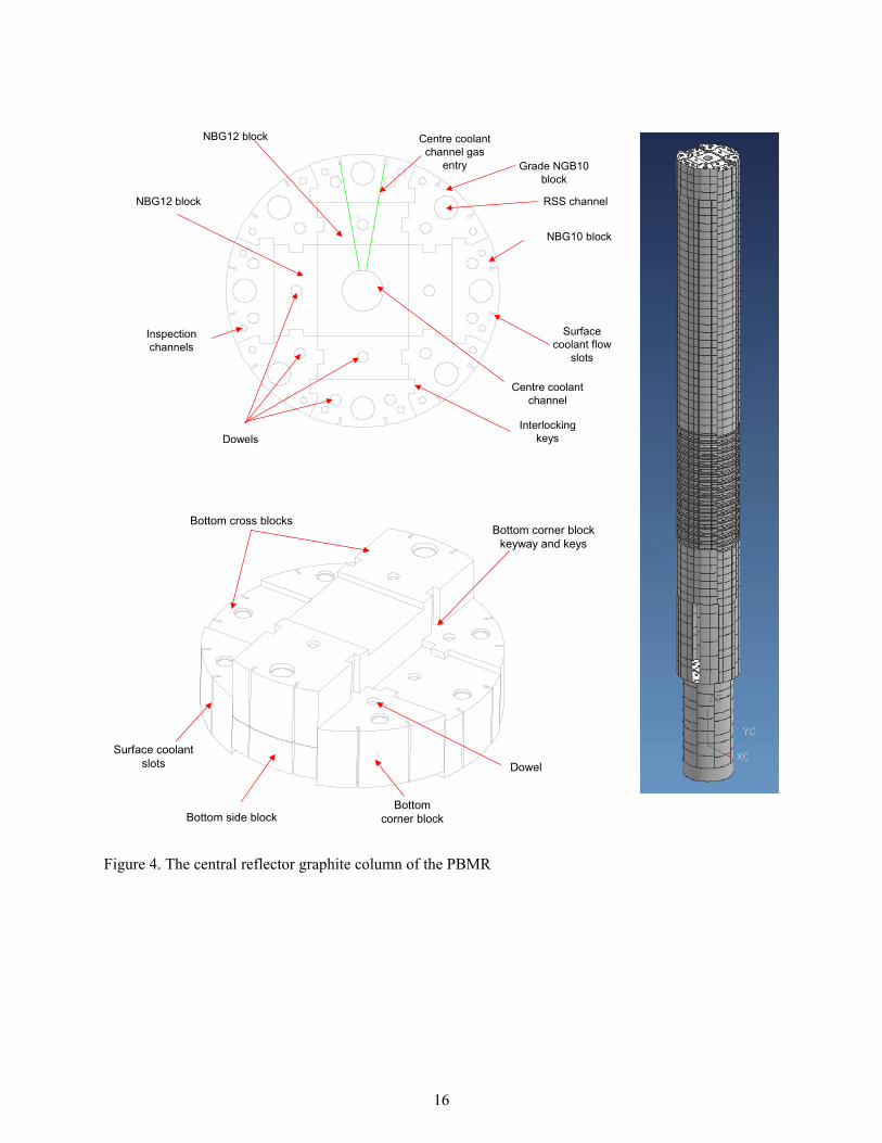
The graphite internals of the PBMR are illustrated in Figure 3. The annular shaped reactor core, which is composed of a bed of fuel pebbles, is supported by the bottom reflector and is laterally restrained by the central reflector and side reflector. The central and side reflectors are constructed from stacks of large interlocking (keyed) graphite blocks. Figure 4 illustrates the central reflector of the PBMR and shows the interlocking and key-structure.
Figure 3. The graphite core internals of the PBMR
16
RSS channel
Grade NGB10block
NBG10 block
Surfacecoolant flow
slots
NBG12 block
Centre coolantchannel
InterlockingkeysDowels
NBG12 block
Inspectionchannels
Centre coolantchannel gas
entry
Bottom cross blocksBottom corner block
keyway and keys
Surface coolantslots Dowel
Bottom side blockBottom
corner block
Figure 4. The central reflector graphite column of the PBMR

17
The currently designated graphite grades for the PBMR core internals are SGL NGB-10 and NGB-12. Both are extruded, pitch coke graphites manufactured at SGL’s Chedde facility in France. The pitch coke used is the same as that currently used for the production of the United Kingdom (UK) Advanced Gas Reactor (AGR) graphite fuel sleeves, and thus there is considerable production experience for this coke and graphite. Consideration is also being given to grade NGB-18, a vibrationally molded graphite.
The volume average thermal flux in the core is 7.90 x 10¹³ n/cm2·s [E>1.86 eV]. The volume average fast flux, which is more relevant since it is fast neutrons that displace carbon atoms and cause the dimensional and property changes, is 3.26 x 10¹³ n/cm2·s [E>0.1 MeV]. Typical lifetime fast fluences for the graphite core internals for a 35 effective full power year life are:
Fuel Pebbles 2.65 x 10²¹ n/cm2 [E>0.1MeV] Upper reflector edge (maximum) 0.21 x 10²² n/cm2 [E>0.1MeV] Outer reflector side (maximum) 3.85 x 10²² n/cm2 [E>0.1MeV] Inner reflector side (maximum 4.73 x 10²² n/cm2 [E>0.1MeV] Lower reflector edge (maximum) 0.53 x 10²² n/cm2 [E>0.1MeV]
The neutron fluence to the central and side reflector is clearly very significant, potentially necessitating their replacement during the life of the reactor. Consequently, the graphite blocks of the central reflector and the inner side reflector (Figures 4 and 5) are designed to be removable. The average fuel temperature in the PBMR varies axially through the PBMR core. The fuel temperature is ~500 °C at the top of the core where the coolant gas enters and increases to ~ 900 °C at the reactor mid plane.
The peak mean fuel temperature is ~1000 °C close to the bottom of the core. The PBMR fuel temperature is always less than 1160 °C. The peak graphite temperatures under normal operating conditions are also likely to be ~1000 °C. Consequently, those areas of the core (inner edge of the side reflector and the outer edge of the central reflector column) that experience high temperatures (>600 °C) and high neutron fluence (>3.0 x 10²² n/cm2 [E>0.1 MeV]) will experience significant distortion due to the irradiation induced shrinkage reversal to growth. Temperature and fast neutron fluence gradients will cause differential stresses in the core, which will relax due to irradiation-induced creep of the graphite.
The PBMR core will also utilize carbon-carbon (Cf/C) composites. Anticipated applications include the core lateral restraints (Figure 5) and the hot gas outlet duct and interface components. Moreover, Cf/Ccomposites will be utilized as metal replacements in selected interface components and for thermal expansion compensation of the core. The majority of these applications will be in low neutron fluence areas where the only affected property will be thermal conductivity. However, applications such as control rod cladding (if adopted) would experience greater fluences, and thus undergo dimensional and property changes. The GT-MHR is expected to use Cf/C composites in a similar manner as the PBMR. [6]

18
Outer SideReflector
Inner SideReflector
CoreBarrel
CoreRadial
Restraints
LateralRestraint
Straps
Figure 5. The inner and outer graphite side reflector of the PBMR
2.2.2.2 Internals and Pressure Vessels- NGNP Prismatic Design. Since there is no NGNP Prismatic Reactor design at present, the GT-MHR components will be used for illustrative purposes. Due to a lack of a conceptual design several different studies have produced different temperatures and core information. The source documents for these values have been referenced.
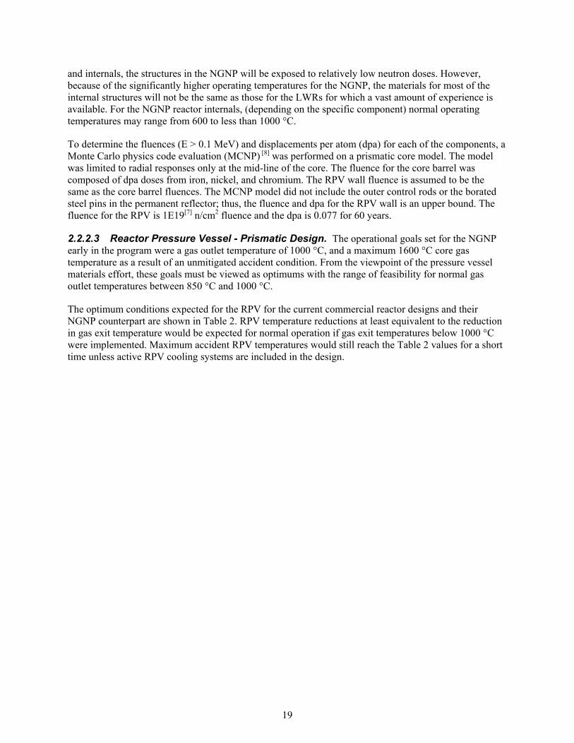
The three main vessels in the GT-MHR design, the RPV, CV, and secondary vessel (see Figure 6), represent the pressure boundary of the primary coolant. The GT-MHR uses a closed Brayton cycle to generate electricity where helium coolant flows out of the reactor directly through the main turbine. The helium exiting the main turbine is re-pressurized to the inlet operational conditions and pumped through the reactor. The NGNP Prismatic Reactor design operational inlet helium pressure and temperature for the reactor is less than 490 °C [7] at a pressure of 7.4 to 8.0 MPa. The inlet helium flows between the core barrel and the RPV maintaining the RPV at a cooler temperature than the core. Nominal operating temperature of the RPV wall is 550 °C [7]. The helium exits the reactor core at temperatures less than 1000 °C at pressures of 7.33 to 7.93 MPa. The pressure drop across the core is ~70 kPa.
The components in the reactor internals system other than graphite that will experience significant radiation exposure are the core barrel, upper plenum shroud, core support floor, upper core restraint, and the shutdown cooling system (SCS; heat exchanger) shell and tubes. The design life of the non-replaceable core internals is 60 years. For some sub-components of those systems where temperatures are excessive, non-metallic materials may be specified. Relative to current light-water reactor (LWR) vessels
19
and internals, the structures in the NGNP will be exposed to relatively low neutron doses. However, because of the significantly higher operating temperatures for the NGNP, the materials for most of the internal structures will not be the same as those for the LWRs for which a vast amount of experience is available. For the NGNP reactor internals, (depending on the specific component) normal operating temperatures may range from 600 to less than 1000 °C.
To determine the fluences (E > 0.1 MeV) and displacements per atom (dpa) for each of the components, a Monte Carlo physics code evaluation (MCNP) [8] was performed on a prismatic core model. The model was limited to radial responses only at the mid-line of the core. The fluence for the core barrel was composed of dpa doses from iron, nickel, and chromium. The RPV wall fluence is assumed to be the same as the core barrel fluences. The MCNP model did not include the outer control rods or the borated steel pins in the permanent reflector; thus, the fluence and dpa for the RPV wall is an upper bound. The fluence for the RPV is 1E19[7] n/cm2 fluence and the dpa is 0.077 for 60 years.
2.2.2.3 Reactor Pressure Vessel - Prismatic Design. The operational goals set for the NGNP early in the program were a gas outlet temperature of 1000 °C, and a maximum 1600 °C core gas temperature as a result of an unmitigated accident condition. From the viewpoint of the pressure vessel materials effort, these goals must be viewed as optimums with the range of feasibility for normal gas outlet temperatures between 850 °C and 1000 °C.
The optimum conditions expected for the RPV for the current commercial reactor designs and their NGNP counterpart are shown in Table 2. RPV temperature reductions at least equivalent to the reduction in gas exit temperature would be expected for normal operation if gas exit temperatures below 1000 °C were implemented. Maximum accident RPV temperatures would still reach the Table 2 values for a short time unless active RPV cooling systems are included in the design.

20
Figure 6. GT-MHR Full Section.

21
Table 2. Comparison of Nominal Parameters for Prismatic and Pebble Bed Design.
RPV Parameter GT-MHR [6]GA-
Prismatic [9]Prismatic NGNP [7] PBMR [10] NGNP PBR [7]
Nominal Gas Outlet Temperature ( C)
850 950 1000 900 1000
Nominal Gas Inlet Temperature ( C)
491 590 490 482 490 c
RPV Normal Operating Temperature ( C)
495 350 470d 300 465 e
RPV Worst Case Accident Temperature ( C)
565 530 560 [7], f 506 560 g
Inlet Gas Pressure (MPa) 7.07 7.07 7.07 8.9 7
Outlet Gas Pressure (MPa) 7.02 7.02 7.02 8.6 6.5?
RPV External Diameter (meters)
8.2 8.2 8.2 7.02 7.06
RPV Nominal Wall Thickness (mm)
100-300 100-300 100-300 120-220 120-220
RPV Nominal Height (meters) 23.7 23.7 24 22 19
Maximum Radiation Fast Fluence in the RPV in the RPV over 60 years (n/cm2)
3x10¹⁸ [11] 1x10¹⁹ [7], h 4.5x10¹⁹ [7] 3.0x10¹⁹
Figure 7 identifies the components of the RPV. The estimated physical dimension of the RPV is a diameter of less than nine meters with wall thicknesses between 100 mm and 300 mm. The vessel itself can be made of welded sections of different thicknesses. The height of the vessel is less than 24 meters.
c 490 °C Based on recent analysis still pending publication d If the temperature is 490 °C on the inside then a temperature drop is assumed to reach approximately 470 °C e 490 0C Based on recent analysis still pending publication f Fig 72, Fig 76 shows 560 °C g 490 °C Based on recent analysis still pending publication h Core Barrel, Neutron Energy Group 2, (5.105E9 x 3600 x 24 x 365 x 60 = 1E19

22
Control Rod Drive Assembly
Refueling Stand Pipe
Control Rod Guide tubes
Cold leg Core Coolant Upper Plenum
Central Reflector Graphite
Annular shaped Active Core
Outer Side Reflector Graphite
Core Exit Hot Gas Plenum
Graphite Core Support Columns
Reactor Vessel
Upper Plenum Shroud
Shutdown Cooling System Module Hot Duct
Insulation Module
Cross Vessel Nipple
Hot Duct Structural Element
Metallic Core Support Structure
Core Inlet Flow
Core Outlet Flow
Insulation Layer for Metallic Core Support Plate
Upper Core Restraint Structure
Control Rods
7m(23 ft)
23.7m(78ft)
2.2m(7ft)
8.2m(27ft) Dia Vessel Flange
Figure 7. GT-MHR Reactor Vessel.

23
2.2.2.4 Cross Vessel – Prismatic Design. The CV is the pressure boundary for the exchange of helium between the RPV and secondary vessel (see Figure 8). The outside diameter of the vessel is expected to be on the order of 2.5 meters with a thickness of less than 100 mm. The CV is welded to the RPV and secondary vessel. To accommodate thermal expansion during operation, the secondary vessel is allowed to slide laterally away from the RPV. The helium flows out of the reactor at a temperature of about 1000 °C in a structural duct inside the CV and returns from the secondary vessel on the outside of the structural duct. The structural duct containing the 1000 °C helium is known as the hot duct. The hot duct uses ceramic insulation on the inside surface to reduce the service temperature to approximately the inlet helium temperature of 490 °C. The ceramic insulation is removable allowing inspection of the hot duct. The hot duct only sees the pressure differential of the core across its thickness. The hot duct is welded to the core barrel at the lower core plenum outlet and is connected to the secondary vessel by means of a metallic bellows. The hot duct is seal-welded to the metallic bellows. The bellows is mechanically connected to the turbine inlet shroud. The outer shell of the CV sees the temperature of the RPV at 550 °C at one end and gradually decreases to the lower temperature of the Power Conversion Vessel. As the CV expands pushing the secondary vessel away from the RPV, the mechanical bellows expands, thus maintaining the pressure boundary between exit and return helium.
The fluence and dpa seen by the CV and hot duct is the same as the RPV and core barrel where the attachment welds are made. The fluence and dpa in the remaining portion of the vessel will see a gradient over the length of the vessel decreasing to negligible values at the secondary vessel.

24
Figure 8. GT-MHR Cross Vessel.

25
2.2.2.5 Secondary Vessel - Prismatic Design. The secondary vessel (see Figure 9) houses the main turbine, generator, and associated turbo machinery and heat exchangers necessary to pump and reheat the helium to 490 °C at inlet pressures between 7.4 and 8.0 MPa. The vessel is on the order of 35 meters tall with outer diameters between 7 and 9 meters. The wall thickness is between 100 and 200 mm. The normal operating temperature for the vessel wall is 200 °C with an off-normal temperature of 300 °C. The design pressure of the vessel is between 5 and 6 MPa. The temperatures and pressure of the NGNP secondary vessel should not change much from the GT-MHR design. The fluence and dpa seen by the secondary vessel is negligible. The two components that will see the helium (<1000 °C) are the metallic bellows and a small portion of the turbine inlet shroud. The turbine inlet shroud is insulated to reduce the temperature seen by the structure except for a small portion that is un-insulated at the connection of the turbine opening. The remaining piping, turbo-machinery, and heat exchangers experience temperatures and pressures that do not challenge current ASME qualified materials. The main turbine, specifically the turbine blades, will be addressed later when more information is available.

26
Generator
Thrust Bearing
Turbine
High Pressure Compressor
Recouperator
Recouperator
Low Pressure Compressor
Precooler/ Intercooler
Cold Gas to Reactor
Hot Gas from Reactor
PCS Vessel
34m(112ft)
8.2m(27ft) Dia. Vessel Flange
Figure 9. GT-MHR Power Conversion Unit.

27
2.2.2.6 Core Internals – Prismatic Design. The estimated lifetime of the core internals is 60 years. The fluence and dpa for these components, except for the control rods and guide tubes, are the same as described for the core barrel and RPV.
The core support floor is a structure of concentric rings welded together with radial beams originating from the center ring. The entire structure rests on supports forged into the lower head of the RPV. The floor supports the mass of the graphite core, core barrel, shroud, and upper core restraints. The structure is maintained at inlet helium temperatures by circulating helium from the inlet underneath the structure and insulating the structure from the core with ceramic or graphite blocks. The mass of the core is approximately 790 metric tons. The bounding dynamic load is the 0.3 g Safe Shutdown Earthquake.
The core barrel (Figure 10) is a metallic cylinder with a diameter of 6.8 to 7 meters, a height of ~14 meters and a thickness of 25 to 50 mm. The cylinder is welded to the core support floor. The core barrel physically restrains the graphite core during earthquakes and from radial thermal expansion during normal operations. The core barrel is centered and restrained in the RPV by keys that fit into corresponding keyways in the RPV. During operation, there is no space between the permanent reflector and the core barrel; the permanent reflector blocks remain in contact with the core barrel. The normal operating temperature of the core barrel is 600 °C. Temperature during off-normal conditions could reach as high as 700 °C operating and off-normal conditions found in American Nuclear Society (ANS) 2003 Gas Reactor Technology Course [12] for the GT-MHR core barrel temperatures to the normal operating temperature of the NGNP core barrel.
The next internals component is the upper plenum shroud. This structure in the GT-MHR concept is metallic and sits on top of the core barrel and supports insulation on the inside surface. Inlet helium flows up the gap between the RPV and core barrel and through the slots in the shroud just above the joint with the core barrel and into the upper plenum cavity. The shroud forms an upper plenum cavity on top of the core and serves as a heat shield to the control rod and instrumentation drives during normal and off-normal operations. During normal conditions, the shroud is maintained at <500 °C by the circulating inlet helium. However, off-normal conditions could result in temperatures approaching 1200 °C in the upper shroud due to the flow reversal and metallic alloys will not survive under these conditions therefore, the issue of metallic or non metallic for this component will need to be considered in the future. The normal operating pressure in the upper plenum is between 7.4 to 8.0 MPa.
The upper core restraint is a structure fabricated of individual hexagonal boxes that have dowels on the bottom, which fit into the top of the upper plenum blocks. Each box is key to six of its neighbors, enforcing the lateral gap between graphite columns and allowing each graphite column to thermally expand in the axial direction independent of the adjacent column. Normal operating temperature for these structures is <600 °C, while off-normal temperatures could approach 1200 °C.
The shutdown cooling heat exchanger (Figure 11) is located in the bottom of the core and is used primarily to remove heat during refueling. The system can be used for normal and off-normal heat removal during shutdown. The upper portion is a helical tube heat exchanger in an environment of inlet helium at <500 °C mixed with <1000 °C flow from the lower core plenum. The tubes are between 12 and 19 mm thick. Water flows through the tubes at rates necessary to keep the water sub-cooled. During startup of the SCS, the helium temperature would increase to 1000 °C for a period of time and even to 1200 °C during startup of the cooling system in off-normal conditions. The operating pressure on the helium side is 7.4 to 8.0 MPa. The pressure on the waterside will vary but will be lower than the normal operating pressure of the reactor. The outside of the tube is 1000 °C and the inside will have pressurized water inside, that is the reason the tubes are ½ to ¾ inches in thickness.

28
Figure 10. GT-MHR Core Barrel.

29
Figure 11. GT-MHR Reactor Shutdown Cooling System.

30
The last internal components are the control rods and their guide tubes. In past prismatic gas reactor core designs, the control rods were metal tubes filled with B4C graphite donuts as shown in Figure 12. The rods transverse the upper plenum inside guide tubes from the upper inner head to just inside the core. The tubes are vented to the reactor pressure. The most important mechanical aspect of the control rods is that they cannot bow or deform during normal or off-normal conditions. The rods must remain straight to enable quick insertion at any time. The control rods that see the highest fluence and temperatures reside on the inside periphery of the core between the inner core and reflector. Normal operating temperatures reach 1050 °C with off-normal temperatures reaching as high as 1400 °C. Considering the high temperatures of these components, it is unlikely that metallic materials can be used solely and structural composites will likely be needed. These control rods see fluences of 6.7E20 n/cm2 per year with dpa values of about 0.56 per year. These high fluences may limit the lifetime of the control rods to less than 40 years; therefore, the fluence and dpa are given on a per year basis. Since control rods may be changed out, the reactor lifetime (~60 years) is not limited by the life of the control rods.
Silicon-carbide/silicon-carbide (SiCf/SiC) composites are being considered as a candidate material for the control rod sheath and guide tubes because metallic materials cannot withstand the level of neutron irradiation and high temperature of 1050 °C or higher found in the core. In addition, there is evidence that SiCf/SiC composites show superior irradiation performance compared to other thermally stable composites such as Cf/C composites. Thus, SiCf/SiC components have the potential to be lifetime components (no change-out required) within the expected high thermal and radiation environment of the NGNP core.
Figure 12. GT-MHR Control Rod Concept.

31
2.2.2.7 Metallic Internals and Pressure Vessels - Pebble Bed Design. There is no NGNP PBR design so the PBMR will be used for reference. A consortium is currently leading the development of this design.
The PBMR is a helium-cooled, graphite-moderated HTR, employing graphite fuel balls or pebbles, 6 cm in diameter, with TRISO ceramic particle fuel dispersed in the pebble. The ceramic fuel consists of a UO2kernel, (0.5mm) coated with layers of pyrolytic carbon and a silicon carbide layer for a total diameter of .92 mm. The helium gas from the reactor outlet is directly coupled to a gas turbine driven generator system forming a closed Brayton cycle. Recent design changes have incorporated a single shaft design where the high- and low-pressure compressor, the turbine, and the generator/reduction gear are driven by the same shaft. An overall view of the reactor and PCU are shown in the PBMR Module Building in Figure 13[13]. Figure 14 shows the components inside the PBMR pressure boundary, which include the reactor, the direct cycle power generation turbine, and high and low pressure turbo compressor components. The generator is outside for maintenance access.
Figure 13. PBMR Single Module Building. [13]

32
Figure 14. PBMR Pressure Boundary. [13]
Figure 15 illustrates the PBMR thermodynamic cycle. The helium exits the bottom of the reactor at a temperature of about 900 °C. The helium then expands in the High-Pressure Turbine that drives the High-Pressure Compressor (HPC). The helium then flows through the Low-Pressure Turbine that drives the Low-Pressure Compressor (LPC). The helium then expands in the Power Turbine, which drives the generator. The high-temperature helium then flows through the primary side of the recuperator where it transfers heat to the low temperature gas returning to the reactor. The helium that passed through the primary side of the recuperator is then cooled by means of a pre-cooler. The helium is then compressed by the LPC and cooled in the inter-cooler. The HPC then compresses the helium to 8.5 MPa. The cold, high-pressure helium stream then flows through the recuperator where it is pre-heated after which it returns to the top of the reactor.
The helium enters the RPV (Figure 16) at a temperature of about 500 °C through the cold gas inlet at a pressure of about 8.5 MPa. The inlet helium flows between the core barrel and the RPV maintaining the RPV at a cooler temperature than the core. Nominal operating temperature of the RPV wall is 380 °C.The helium moves downward between the hot fuel spheres in the core barrel (Figure 17).
The PBMR consists of a vertical steel RPV (Figure 16) 30 m high with an inside diameter of 6.2 m. [14]
The pressure vessel material is ASME SA 508[15]/SA 533[16]. The pressure vessel is lined with a layer of graphite bricks. The core barrel surrounds and supports the graphite reflector (see Figure 5). This graphite

33
layer serves as an outer reflector for the neutrons generated by the nuclear reaction and a passive heat transfer medium. The graphite brick lining is drilled with vertical holes to house the control elements. This graphite reflector encloses the core where the nuclear reaction takes place. Helium flows through the pebble bed and removes the heat generated by the nuclear reaction. Total height of core barrel is 22 m with an outside diameter of 5.85m. [17]
The core barrel material is 316 stainless steel. The design of the RPV and core barrel meets ASME Section III, Subsections NB and NG respectively. The Decompression Loss of Flow Accident (DLOF) maximum temperature for the core barrel is 621 °C and is covered under ASME Code Case N-201. The DLOF for the RPV is 490 °C and is covered under ASME Code Case N-499.The design life of this system is 40 years.
The fluences for the RPV, core barrel and reactor metallic internals are expected to be comparable to those discussed earlier for the GT-MHR.
Figure 15. PBMR Thermodynamic Cycle. [13]

34
Figure 16. Reactor Unit Vessel Assembly.

35
Figure 17. Core Structure Assembly. [14], [17]

36
2.2.2.8 Intermediate Heat Exchanger. A current NGNP requirement states that 10% of the heat from the primary loop can be diverted to the production of hydrogen. The remaining 90% will be used to produce electricity. To accommodate this requirement, an IHX within a pressure vessel would be employed to divert heat from the primary side of the reactor to a hydrogen production plant. The heat exchanger needs to isolate hydrogen production plant equipment from the radioactive contaminants in the helium coolant and prevent any backflow of hydrogen or heat transfer fluids from the hydrogen plant back into the primary He loop. These cross contamination issues may be handled through equipment design, pressure differentials between the loops, or usage of secondary heat exchangers to ensure isolation. The primary circuit IHX may be employed in either a direct or indirect cycle application. The indirect cycle places the IHX and its pressure vessel directly between the reactor core and the PCU. The direct cycle diverts 10% of the reactor outlet gases to an IHX as a bypass around the gas turbine.
By definition, the IHX must handle the temperatures of the heated gases exiting the reactor core. The operational temperature of 850 °C (for the GT-MHR) is near the expected regulatory limits for the most heat resistant alloys available at this time. Accident situations for may take the IHX beyond the realm of feasibility for a metallic material. For these reasons, depending on specific NGNP design, intermetallic or ceramic heat exchange components may have to be considered in the future. Although potentially feasible, such heat exchangers would require considerable development and extensive regulatory work to be licensed for reactor use in the primary system. In addition to the thermal requirements, the IHX must operate with some pressure differential and would need to be able to withstand the thermally induced stresses from expansion and contraction resulting from a loss of flow from either primary or secondary sides. The dimensional changes resulting from differential thermal expansion or contraction would be one of the major issues that would need to be overcome with use of intermetallic or ceramic heat exchange systems.
It is believed that due to the factors noted above, the IHX for the NGNP will be constructed of very high-temperature metallic materials and the structure will be designed to conform to ASME Code requirements. Therefore, the IHX will need to be controlled by the NGNP design to temperature, pressure and time exposure limits within the ASME Code capabilities of the structure. Therefore, systems will by necessity be in place that will allow the IHX to survive accident conditions.
2.2.2.8.1 Direct Cycle Application. The direct cycle application would require a compact heat exchanger sized for 10% of the reactor heat load to be placed inside or very close to the secondary vessel. The turbine inlet would have a small leg diverting primary coolant to the heat exchanger. The secondary side of the heat exchanger would contain coolant coming from the hydrogen production plant, probably from a secondary heat exchanger. The outlet of the primary side would re-enter the primary loop downstream of the turbine or in one of the turbine stages.
The primary side of the IHX (depending on design) could have 1000 °C helium flowing through it with an exit temperature of 900 °C or greater. The outlet of the secondary side of the IHX would be 950 °C to 975 °C with a secondary inlet side temperature of about 500 °C. To place a direct cycle IHX in the secondary vessel would require the surface area density to be greater than 1000 m2/m3. The pressure drop in each IHX leg must not exceed 2% of total pressure in each leg. The operating pressure in both legs is 6.7 to 7.1 MPa with the secondary pressure exceeding the primary pressure by 0.1MPa (if pressure is used to prevent primary gas flow into the secondary system). Depressurization of the secondary side while the primary remains hot and at pressure would create significant thermal stress within the IHX. Membrane stresses in the IHX may also be affected, but only as a function of the IHX design and the overall pressure differential. These off normal stress states may challenge the material properties at operating temperatures. The radiation fluence on the IHX is negligible inside or immediately adjacent to the secondary vessel. A pressurized core conduction cool-down event would push the average primary inlet

37
temperature up to 1200 C for a short period. The full consequence of this temperature spike will have to be evaluated during design.
The primary advantages of the direct cycle IHX would be its relatively small size and the potential of incorporating the hardware within the secondary vessel. However, the direct cycle approach almost guarantees that a second heat exchanger will be needed to ensure isolation of primary system contamination and potentially allow change from He to a different operating fluid.
2.2.2.8.2 Indirect Cycle. The indirect cycle application would require the IHX to be sized to handle the entire heat load of the reactor. The IHX is placed between the RPV and secondary vessel with structural ducts between the RPV and IHX and between the IHX and the main turbine/generator. The primary side of the IHX would see flow from the reactor and exit to the turbo-machinery pumps, intercoolers, pre-coolers and recuperator for conditioning the gas back to reactor inlet conditions. The IHX secondary side outlet helium would run the main turbine/generator. The secondary balance of plant would return the helium coolant to the secondary IHX inlet conditions using normal turbo machinery. The heat for the hydrogen plant would be drawn from the secondary outlet of the IHX upstream of the turbine. This configuration would isolate both the hydrogen plant and the main turbine/generator from the radioactive contamination in the primary leg. Such secondary vessel isolation is probably the biggest advantage of this approach.
The primary IHX inlet temperature could be up to 1000 °C and the secondary outlet temperature could be 950 °C-975 °C (depending on design). The pressure of the primary inlet would be nominally 7 MPa. The primary outlet and the secondary system pressures would need to be determined during design. The conditions for 95% efficiency would be equivalent to those discussed for the direct cycle. The fluence will be between that of the secondary vessel and RPV depending on the distance the IHX is placed from the RPV and the presence of shielding materials, though this could likely be reduced to an inconsequential level by engineering approaches, if warranted. If the secondary side experiences a loss of flow without scram, the entire primary side heat load is placed on the primary turbo-machinery, coolers, and recuperators to reduce the temperature and bring the pressure back up to inlet conditions. This IHX approach could also see the 1200 C spike in an off-normal condition.
Although an indirect cycle IHX would radically change the configuration of the systems external to the NGNP RPV, there are very good reasons to consider the approach. The major advantage of the indirect cycle IHX is that all the secondary vessel components are outside the primary loop. This difference would make the power conversion equipment easier to maintain and would limit the complexity of the equipment in the primary loop. Although difficult to quantify, this approach may also allow more efficient sizing of turbo machinery for processing the primary gas back to reactor conditions because both the primary and secondary systems would help handle the heat load in an accident situation.
2.2.2.8.3 IHX Types. Three types of heat exchangers have been suggested for the IHX based on efficiency and potential feasibility: the printed circuit, the plate and fin, and intermetallics or ceramic open-cell heat foam. The more traditional, helical coiled tubes in a tube sheet design may also be feasible for the indirect cycle IHX. [18] Printed circuit heat exchangers (See Figure 18) rely on thermal diffusion welds between plates. The plate and fin type heat exchangers use high-temperature brazing to join the plates and seal the system. Intermetallics or ceramic heat exchangers hold potential for the NGNP, but the required unit would be several times larger than anything currently manufactured. Open cell graphite and intermetallic ceramic foam materials with exceptional thermal conductivities of up to 150 W/m K have been developed recently, though methodologies to use the thermal conductivity while retaining a pressure boundary must still be developed.

38
Each heat exchanger configuration has advantages and disadvantages to consider. Of the metallic systems, the printed circuit and plate-fin types allow the greatest surface area per unit volume of gas to minimize size. The tube type heat exchangers are more bulky and less efficient, but easier to build in a manner that can handle severe thermal transients. The pressure boundary for the printed circuit heat exchanger depends on the diffusion welds between every layer. The plate-fin pressure boundary depends on the high-temperature brazing material and the successful furnace brazing of an entire unit without any defects. In addition, the braze metal must take the stresses resulting from thermal transients. Intermetallic and ceramic heat exchangers may effectively eliminate the concerns of operating at high steady state temperatures but have major issues arising from their inherently brittle nature coupled with the need to handle thermal transients.
Figure 18. Printed circuit type heat exchanger.

39
2.3 Quality Assurance Requirements
All work performed to support the Technical Program for the NGNP Materials R&D Program will utilize the national consensus standard ASME NQA 1997, "QA Program Requirements for Nuclear Facilities Applications," and Subpart 4.2 of ASME NQA 2000, “Guidance on Graded Application of Quality Assurance (QA) for Nuclear-Related Research and Development,” for project-specific materials development activities.
The QA requirements for specific projects under the NGNP Materials R&D Program will be specified in project-specific Quality Plans and project-specific technical specifications. The project specific quality plans will include the necessary management controls commensurate with the project work scope and importance to the program. There are currently two Project specific quality plans, One at the Oak Ridge National Laboratory (ORNL) and the other at INL; both of them are DOE National Laboratories. At the ORNL Laboratory the quality plan is entitled “Quality Assurance Plan for the Next Generation Nuclear Plant Materials Program at Oak Ridge National Laboratory”, QAP-ORNL-NGNP-01, Rev. 1. The INL quality plan is entitled “Quality Program Plan for the INL NGNP Materials R&D Program # PLN-1792. The DOE Nuclear Energy Research Initiative university work activities may be managed under the umbrella of either the ORNL or INL Quality Plans mentioned above.
The material’s development effort has a broad scope and involves many different applications that fit within the scope of the ASME NQA-1 –1997 Standard or the ASME nuclear construction code. These unique application materials will require extensive R&D and specialized testing and qualification using various national or international methods and standards. This material development effort will require developing a common acceptable framework that will provide regulatory acceptable material with the appropriate certifications to the users.
Procurement actions required for development of materials shall be controlled as required to generate a solid qualification basis for potential future material procurements and installation and/or use related to pilot or production facilities.
There are key QA controls that are needed for these efforts and these shall be tailored and graded to provide the necessary level of assurance and documentation along with needed management controls to provide a material product that will be usable within the nuclear regulatory environment. Examples of these key QA controls are as follows:
Process Control- Experiments, tests, and material processing shall be performed to a written instruction outlining the required steps/actions. Results shall be documented in appropriate lab notebooks, travelers, run sheets or technical reports to provide processing information that is complete and available to the NGNP Program users.
Data Management-Define the methodology and industry being used to control, develop, qualify and store electronic information to be used in the materials qualification process. This would include existing information that may be derived from numerous sources over large spans of time or multiple individuals. This information may be electronic, hard copy technical papers and/or journal articles or existing material standards of material organizations.
Control of Purchased Materials, Items, and Services-These shall be considered if the quality of work results is dependant on the pedigree of materials, items or services and the assurance of conformance is documented. The specific name, manufacturer, chemical information, and model or serial number shall be documented for all materials and chemicals used in development processes that could relate directly to the quality of the product.
40
Software Management- The use of software in the materials development process shall be controlled by the individual users to assure accurate and reliable results that are obtained by established methods, qualified to known software management standard and documented, repeatable, and retrievable.
Management Reviews and Assessments- The use of peer/independent review activities shall be used during the initial stages of the NGNP Materials R&D Program and as the Program matures program management assessments shall also be performed to ensure the quality of the material program activities.
2.4 ASME Codification
Once appropriate materials have been designated for the NGNP use, it will be necessary to gain ASME boiler and pressure vessel (B&PV) Code acceptance of those materials at the desired operating conditions. Since the ASME B&PV Code Section III establishes the rules for the construction of nuclear pressure vessels and many power plant components, ASME acceptance of the designated materials at the temperatures and environments expected during NGNP use is a significant programmatic step forward. The ASME B&PV Code is not the only national consensus standard that will have to be satisfied. However, the ASME B&PV Code is believed to be the most significant from the perspective of actually designing and constructing an NGNP demonstration plant.
It is important to note that once a material has been approved for use by the ASME Subcommittee on Materials under Section II, it is still necessary to interact with the other construction subcommittees, especially the Subcommittee on Nuclear Power, the Subcommittee on Design, and the Subcommittee on Pressure Vessels, to gain full ASME B&PV Code acceptance. Within the Subcommittee on Design, the Subgroup on Elevated Temperature Design works on issues affecting Section III Division I Subsection NH of the B&PV Code, which governs design of elevated-temperature Class 1 nuclear components.
2.4.1 ASME Boiler and Pressure Vessel Code Background
The charter for the ASME B&PV Code committee is:
To establish the rules of safety governing the design, fabrication, and inspection during construction of boilers and pressure vessels, and to interpret these rules when questions arise regarding their intent.
Many engineers consider the goal of the ASME B&PV Code is “to maintain the pressure boundary”. The ASME B&PV Committee has a large number of reporting subcommittees. The Subcommittee on Materials is responsible for Section II of the B&PV Code; the Subcommittee on Nuclear Power is responsible for Section III, Nuclear Power Components. The current B&PV Code has been in use for many decades and Section III has matured greatly over the last 30 years. But it was written mainly for pressurized and boiling water reactors that typically have temperature limits below 427 °C. Section III, Division I, Subsection NH addresses temperature limits up to 816 °C but only for a limited number of materials. Due to the fact that the NGNP reactor is a helium-cooled reactor operating in excess of the temperature limits of 816 °C numerous areas of the ASME B&PV Code will need to be modified or expanded, including (but not limited to) new materials approved for use, new temperature limits for existing approved materials, new design considerations, new weld procedures, new equipment considerations, and more. Other sections of the ASME B&PV Code have temperature limits for certain materials in the 816 to 900 °C range but these temperature limits are still below what is desired for NGNP balance-of-plant and hydrogen generation uses. The current Section III Subsection NH criteria and material coverage originate largely from the liquid-metal reactor (LMR) program of the late 1960s, 1970s, and early 1980s. In the late 1960s the Atomic Energy Commission initiated a Materials and Structures Technology program and simultaneously asked the ASME B&PV Code Committee to charge an

41
expanded subgroup on Elevated Temperature Design with developing the design rules that eventually provided the basis for Subsection NH. That subgroup was staffed largely with LMR program participants. A High-Temperature Structural Design Technology task within the nationwide Materials and Structures Technology program supported the development and experimental confirmation of design criteria to guard against creep, creep-fatigue, and ratcheting failures. The Mechanical Properties Design Data task provided the uniaxial data for design and quantification of the criteria. In companion efforts, the High-Temperature Structural Design Technology task provided recommended constitutive equations for the required inelastic design analyses, and the Design Data task provided the uniaxial stress-strain and creep data needed for designers to implement the equations. All of this work was based on experimental data from common heats of materials, so that the resulting design methods, criteria, and data were as consistent as possible. A recent Argonne National Laboratory report, prepared for the NRC provides a good overview of subsection NH and its associated cases and their shortcomings for HTGR components. [19]
2.4.2 Current ASME B&PV Code Material Acceptance Criteria
Section II of the ASME B&PV Code is considered a service subcommittee because it addresses materials approved for use by the construction subcommittees. Besides various specifications for ferrous, nonferrous, and welding materials, Section II also contains material properties such as Young’s modulus, thermal conductivity, allowable stresses and stress intensities, etc. To achieve B&PV Code acceptance, specific material information must be provided to the appropriate subcommittees. Appendix 5 (contained in Part D of Section II of the ASME B&PV Code) lists the guidelines established for approval of new materials. The items in the Section II guidelines may require a significant effort to satisfy. The higher temperatures and operating environment for the NGNP may require even further efforts. Once the material is accepted it will then be used for construction approval in Section III, Subsection NH. The design rules and guidelines for Subsection NH are discussed in detail in Section 2.4.4 of this document.
2.4.3 ASME B&PV Code Process
The preferred approach to gaining ASME B&PV Code acceptance of NGNP materials and construction details is to incorporate the materials into Section II and write applicable rules for NGNP construction, where necessary. Below the level of subcommittee there are subgroups, working groups and special working groups. The subgroup, working group, and special working group report to the subcommittee where the details of the rules governing construction are proposed, debated, and approved. Participation on behalf of the NGNP Materials R&D Program at these levels is essential. The participation task is discussed in Section 3.5.
Other ASME subcommittee groups may be identified once further details of the plant design become finalized. Due to the lack of current high-temperature, gas-cooled reactors, new groups (e.g., under Section XI of the ASME B&PV Code) may need to be added to the organizational structure.
Code Cases are an alternative option for gaining ASME B&PV Code acceptance. Code Cases are used when it is necessary to clarify the intent of existing Code requirements or, when the need is urgent, to provide rules for material or construction issues not covered by existing Code rules. Code Cases are also useful since one can quickly determine the B&PV Committee’s acceptance of an idea and the limited scope of a Code Case may gain easier NRC acceptance. However, a potential downside of a Code Case is its limited (3-year) effective period, unless it is renewed.
42
A subcommittee will consider a Code Case (3-year effective period) permitting use of new material provided:
Evidence can be provided that a request for material specification coverage has been made
The material is commercially available and can be purchased per proposed specification
– Inquirer shows reasonable demand
– Specification form clearly described
– Requirements of Appendix 5 satisfied.
2.4.4 ASME B&PV Code Section III Subsection NH
The design rules of subsection NH for Class 1 elevated-temperature components consist of:
1. Load-controlled (primary) stress limits (Section III, Div I-NH Appendix I),
2. Strain, deformation, and fatigue limits (Section III, Div I-NH Appendix T).
The load-controlled stress limits are in the form of time-dependent allowable stresses based on both short-time tensile test results and long-term creep test results. Allowable stress reduction factors for weldments are given, as are reduction factors to account for the degrading effects of prior service. Only elastic analysis results are required to satisfy the primary stress limits.
The second category of design rules – strain, deformation, and fatigue limits – are much more problematic. These rules deal with complex behavior, resulting from primary plus cyclic secondary and peak stresses. They are aimed at preventing failures due to excessive deformation, creep-fatigue damage, and inelastic buckling, and they generally require inelastic design analysis results for their satisfaction. The rules include strain accumulation limits, creep-fatigue criteriai, buckling limits, and special limits for welds. The materials that are currently covered, allowable life times, and maximum allowable temperatures are limited in Subsection NH, as shown in Table 3. Only the temperature limits for Alloy 800H come close to those required for the NGNP vessels. Coverage for none of the materials is adequate for the very high-temperature NGNP components.
Aside from the fact that most preliminary candidate NGNP materials are not included in Subsection NH, there are several generic shortcomings that will require resolution. First, the maximum temperatures permitted will have to be significantly increased. Second, allowable time-dependent stresses will have to be extended beyond the current 300,000 h maximum to 600,000 h. Third, environmental effects (impure helium) need to be incorporated into the failure criteria, particularly creep-fatigue.
2.4.5 Confirmatory Testing of Methodology
Time-dependent structural tests provide data that either validates the HTDM or leads to changes in inelastic design analysis guidelines or Code rules. The role of structural tests will be even more important for the NGNP materials because of the lack of long-term service experience. The need for very-high-temperature, time-dependent tests of structural models was identified to (1) provide a better understanding
i As currently formulated in Subsection NH, the creep-fatigue rules are based on a linear damage accumulation rule, an interaction diagram to account for the synergistic effects (and for environmental effects in the case of ferritic steels), and multiaxial strength theories for both fatigue and creep rupture.

43
of structural behavior and failure modes, (2) validate inelastic analysis methods, and (3) provide some applications feedback to the Code.
It should be emphasized that the structural tests to be performed in this Materials Program are not tests of NGNP component structures. Rather they are tests of carefully chosen, simple, but representative, geometrical and metallurgical features subjected to time-varying thermal and mechanical loadings. The tests are contrived to explore key features or problem areas of the methodology. Past examples include beams, plates; thick-walled cylinders subjected to thermal gradients, capped cylindrical shells, and nozzle attachments. Cylinders and plates with notch-like discontinuities and with axial or circumferential welds were included. The latter two types of tests will be particularly important to NGNP because of the two major NRC concerns of weldments and discontinuities.
While not strictly a part of the design methodology, the safety assessments required for licensing depend on much of the same materials and structures database. A particular need is for a flaw assessment procedure capable of reliably predicting crack-induced failures as well as the size and growth of the resulting opening in the pressure boundary. High-temperature flaw assessment guides have been developed in France, Japan, and the United Kingdom, and work on elements of a procedure is currently underway in the United States under Pressure Vessel Research Council sponsorship. An overall proven procedure, which will require inelastic analysis of flawed components, characterization of sub-critical creep and fatigue crack growth, and a structural failure criterion, does not exist however. These will be developed for the NGNP materials.
Experience has shown that once detailed design assessments are undertaken, shortcomings and issues with the design methodology and criteria will arise, requiring additional R&D for their resolution. In addition, the licensing process will likely result in the identification of further R&D requirements, as it did in the case of the Clinch River Breeder Reactor Project (CRBRP). Thus, it is anticipated that the HTDM project will continue throughout the design effort to resolve the shortcomings, issues, and regulatory concerns.
Table 3. Current Subsection NH materials and maximum allowable times and temperatures
Temperature (°C) b
Material Primary stress limits and
ratcheting rules Fatigue curves
304 stainless steel 816 704
316 stainless steel 816 704
2 1/4 Cr – 1 Mo steel 593b 593
Alloy 800 H 760 760
Modified 9 Cr – 1Mo steel (Grade 91) 593b 538 a. Allowable stresses extend to 300,000 h (34 years) unless otherwise noted. b. Temperatures up to 649 °C are allowed for not more than 1000 h.
Four current ASME B&PV Code cases and a draft Code case are relevant to the HTDM project.
1. Case N-499 was developed for HTGRs. It permits Class 1 components fabricated from SA-533,[16] Grade B steel to exceed the normal 371 °C low-temperature design limit for short periods for Levels B, C, and D events. A similar case might be developed for the NGNP vessel material under off-normal conditions.

44
2. Case N-201 provides rules for construction of core support structures made of ferritic steels, austenitic stainless steels, and high-nickel alloys, and having metal temperatures not exceeding those in Section II, Part D. This Case, with modifications, might be useful for the metallic core internals of NGNP. The basis for the Case is the same high-temperature structural design methodology as that on which Subsection NH is based.
3. Code case N-253 provides rules for Class 2 and 3 components for elevated temperature service. Unless exemption rules are met, the case essentially defaults to the criteria of Subsection NH.
4. Code case N-290, which covers expansion joints in Class 1 liquid-metal piping, can serve as a starting point for criteria and design methods for the NGNP bellows.
5. A draft Code case developed in the 1980s for design of Inconel 617 to 982 °C is directly pertinent to NGNP. [20] The original request for the case came from DOE and General Electric. The specific gas-cooled reactor component of primary interest was a steam-methane reformer, which was to be part of the reactor primary pressure boundary. Materials of potential interest included nickel alloys 800H, X, and Alloy 617. Alloy 617 was chosen for the case because it was a leading choice of designers, and a reasonable database of material properties existed. The case was developed by an ad hoc group of the Subgroup on Elevated Temperatures Design (SG-ETD). The case was subsequently approved by SG-ETD and submitted to its parent group, the Subcommittee on Design, for approval. However, further action on the case was suspended when the DOE project was canceled. The case is of value to NGNP because it can serve as a springboard for establishing NGNP Code rules. It was the result of a five-year effort of experienced high-temperature materials and structures engineers, as well as gas-cooled reactor project participants. It also had the participation and input of researchers from the Japanese Atomic Energy Research Institute (JAERI) and the Institute for Chemical Technology (KFA) in Germany. The draft case, while having the same framework as Subsection NH, has several unique features that are ramifications of the very-high-temperature material behavior. This behavior includes (1) the lack of clear distinction between time-independent and time-dependent behavior, (2) the high dependence of flow stress on strain rate, (3) softening with time, temperature and strain. Therefore, the design rules of Subsection NH that are based on the separation of time- and rate-independent response, or on strain-hardening idealizations of material behavior required careful reconsideration in the case. For example, the case specifies that inelastic design analyses for temperatures above 649 °C must be based on unified constitutive equations, which do not distinguish between time-independent plasticity and time-dependent creep.j The draft case also recognizes that significant environmental effects on Alloy 617 could exist, and it recognizes that extended exposure at elevated temperature may cause a significant reduction in fracture toughness of Alloy 617, thus introducing an additional failure mode – brittle fracture – to be considered. Finally, because of the uncertainties in data extrapolation and the lack of experience in designing to such high temperatures, where allowable stresses are very low, the draft case is limited to design lives of just 100,000 h or less.
Table 4 lists the ASME Code status and design allowable values for the candidate materials being considered for the reactor vessel and IHX and high-temperature components. As can be seen, there will be a lot of standards and code work required to have materials ready for the ASME B&PV Code Section III design process. For a list of potential candidate materials being considered for all internals, as well as the
j This is also the case for the high-alloy ferritics (e.g., 9Cr – 1Mo steel) at the upper end of their useful temperature range.

45
other high-temperature components likely to be constructed from metallic alloys, see Section 3.1.2, Table 6.

46
Table 4. ASME Code Status and Design Allowable Values.
Material/UNS ASME Code Status Code Maximum Temperature ( F) Product Form
Stress Value (ksi)
800H/NO8810 (also ferritic steels, 304, 316)
Code Case N-201-4, (Class CS Components in Elevated Service, Section III, Div. I)
1400 °F (760 °C)
602CA/NO6025 Code Case 2359-1 (Section I and Section VIII, Div.1)
1800 °F (982 °C) Forgings, bar, plate sheet strip, welded and seamless pipe and tubing
0.32(Section VIII only)
617/NO60617 Code Case 1982-1, (Section VIII, Div.1)
1800 °F (982 °C) 0.73 (creep-fatigue,thermal ratcheting and environmental effects must be considered)
617/NO60617 Code Case 1956-7, (Section VIII, Div.1) Annulled.
1650 °F (899 °C) Plate, rod, bar, forgings and seamless tube
1.7(creep-fatigue,thermal ratcheting and environmental effects must be considered)
617/NO60617 Draft Code Case, not completed, (Section III, Subsection NB, Class 1 Components, Subsection NH, Class 1 Components in Elevated Temperature Service)
1800 °F (982 °C)
X/NO6002 Section II, Part D, Table 1B, (Section I, Section III, Class 2 and 3, Section VIII, Div. 1)
1650 °F (899 °C)(not all product forms—fittings, pipe, tube, plate, rod)
Forgings, bar, plate sheet strip, welded and seamless pipe, tubing, and fittings
1.2
XR-Mitsubishi Materials Unknown Unknown Unknown Unknown 230/NO6230 Code Case 2384 (Section
VIII, Div. 1) 1800 °F (982 °C) Strip, plate, bar,
welded pipe and tube, seamless pipe, tube, and fittings, forgings
0.45
HR-120/NO8120 Code Case 2315, (Section VIII, Div. 1)
1650 °F (899 °C) Strip, plate, bar, welded pipe and tube, seamless pipe, tube, and fittings, forgings
1.4
9Cr-1MoVNb, Grade 91 Section III, Class 1 593 °C Plate 4.3

47
3 TECHNICAL PROGRAM
The technical program is described in this section first by discussing the candidate materials for the components (Section 3.1), and then a breakdown of each of the specific projects (Sections 3.2 through 3.16).
3.1 Component Candidate Materials
A variety of options have been identified for potential use of materials in the NGNP reactor and balance of plant components. These options originated through an initial look at the materials issues for a very high-temperature reactor in January 2003[1] and a much larger, focused NGNP materials options identification activity that included meetings at INEEL and ORNL in July 2003. The information shown in this section is a summary of the options identified because of these activities and any others that have been identified since the July meeting.
3.1.1 Reactor Core Graphite, Reflector, and Supports
Graphite will be the major structural component and nuclear moderator in the NGNP core. The graphites used previously in the high-temperature gas reactor programs in the U.S., H-451, are no longer in production and thus replacement graphites must be found. Hence, it will be necessary to qualify new grades of graphite for use in the NGNP. Fortunately, likely potential candidates currently exist, including fine-grained isotropic, molded or isostatically pressed, high-strength graphite suitable for core support structures, fuel elements and replaceable reactor components, as well as near isotropic, extruded, nuclear graphite suitable for the above-mentioned structures and for the large permanent reflector components. These candidates would meet the requirements of the draft ASTM materials specification for the Nuclear Grade Graphite.
The fine-grained isotropic, molded or isostatically pressed, high-strength graphite suitable for core support structure includes Carbone USA grade 2020 and Toyo Tanso grade IG-110. Toyo Tanso grade IG-110 was used in the Japanese HTTR for fuel blocks and in the Chinese HTR-10 PBR. These fine-grained materials are suitable for the fuel elements and replaceable reactor components.
Graphite is a complex material whose structure and properties reflect the raw materials used in its manufacture, the processing techniques, and the thermal history of the material. Our understanding of neutron irradiation damage in graphite is well developed. However, fundamental models relating structure at the micro- and macrostructural level to the irradiation behavior are less well developed.
Graphite comprises a composite structure manufactured from a filler coke and pitch binder. Nuclear graphites are usually manufactured from isotropic cokes (petroleum or coal-tar derived) and are formed in a manner to make them near-isotropic or isotropic materials. After baking (carbonization), the artifact is typically impregnated with a petroleum pitch and re-baked to densify the part. Impregnation and re-bake may occur several times to attain the required density. Graphitization typically occurs at temperatures >2500 °C. Additional halogen purification may be required. Typical manufacturing times are 6-9 months.
The forming and densification processes impart property variations within the billet. The properties will be somewhat different in the forming direction compared to the plane perpendicular to the forming direction. Moreover, a density gradient will exist from billet edge to center. These variations must be quantified for the selected grades of graphite. In addition, variations in property will arise from billet to billet within a batch, and between production lots. Finished graphite is machined to the complex geometries required for the reactor components (fuel elements, reflector blocks, core support post, etc.).

48
Early in the program, it will be necessary to review and document the existing data, from all available sources, on the properties of these new grades of graphite. Irradiation data from ongoing experiments in the Petten Reactor (European Union program) will be of great value. A complete properties database on the new (available) candidate grades of graphite must be developed to support the design of graphite core components. Data is required for the physical, mechanical (including radiation-induced creep) and oxidation properties of graphites. Moreover, the data must be statistically sound and consider in-billet, between billets, and lot-to-lot variations of properties. The data will be needed to update and benchmark existing design models for graphite performance. Since the available near-isotropic, extruded graphites are somewhat similar to the prior grade H-451, design models for H-451 can be incrementally adjusted for the currently available graphites as new data becomes available. This review will provide data that will be input into the preliminary selection process.
As part of the preliminary selection process, a radiation effects database must be developed for the currently available graphite materials. As mentioned above, there is the potential to leverage data from European Union activities in the area of irradiation experiments on PBMR graphites (Petten Reactor irradiation experiments are currently being initiated). However, it is anticipated that a substantial number of additional graphite irradiation tests will be needed to complete the database. Since NGNP graphite service temperatures are anticipated to be as much as 200 °C greater than that in the Fort St. Vrain with H-451 graphite, additional data are required for all properties at these higher temperatures, including radiation damage effects. Therefore, in order to be qualified for the NGNP, existing graphite behavior models need to be modified based on sound materials physics and then validated/verified against new data for the currently available graphite grades. Property data must support the service conditions, including effects of higher temperature, helium gas (plus air and water), and neutron irradiation effects. Irradiation creep data for the candidate graphites must also be obtained.
New near isotropic, extruded, nuclear graphites have been developed in the United States and Europe for the South African PBMR. The new, currently available graphites are GrafTek (UCAR) grade PCEA—a petroleum coke graphite, and SGL Grade NBG-10—a pitch coke graphite based on UAGR fuel sleeve graphite. This graphite may be a candidate for the fuel elements and replaceable reactor components.
Graphites suitable for the large permanent reflector components are currently in production (e.g., SGL grade HLM or GrafTek [UCAR] grade PGX). Some data are available for these graphite grades. Grade PGX was used for the permanent reflector of the Japanese HTTR, also PGX and HLM were used in Fort St. Vrain for the core support and permanent reflectors respectively. Fine-grain, high strength, graphites are available from POCO Graphite, Inc. However, the available billet sizes are small and very expensive, thus not suited for NGNP core applications.
Near-isotropic, extruded, nuclear graphites (e.g., grade H-451 manufactured by SGL Carbon) were developed in the 1970s for large helium cooled reactors such as the Fort St. Vrain reactor. However, grade H-451 graphite has not been manufactured in the United States for more than 25 years.
There is a substantial database for U.S. standard grade qualified for nuclear service Grade H-451, including data for the effects of neutron irradiation on the properties, statistical variation of properties, oxidation behavior, etc. This body of data was considered sufficient to license the Fort St. Vrain reactor. Moreover, graphite behavior models were developed for Grade H-451 graphite. Fine-grained isotropic, molded or isostatically pressed, high strength graphites suitable for core support structure (e.g., Carbone USA grade 2020 or Toyo Tanso grade IG-110) are available today. These fine-grained materials are suitable for the fuel elements and replaceable reactor components, but they cost about three or four times more than fine-grain, near-isotropic, extruded graphite.

49
3.1.2 Reactor Internals
The components addressed in this subsection may be classified as core supports and core internals. They include:
Core barrel
Inside shroud
Core support floor
Upper core restraint
SCS shell
SCS tubes.
The following sections will develop additional data used to make materials choices for intermediate and high-temperature materials for the NGNP reactor internals and balance of plant components. Table 5 lists possible choices from an initial materials scoping document [1] and additional information developed during reviews and discussions between materials experts at several meetings.
Depending on the specific component, the normal operating temperatures will range from 400 to 1000 °C.However, the maximum temperature estimated for accident conditions ranges could be higher from one component to another. In regard to loading, these components are not pressure boundary components, except for the SCS tubes. In some cases, however, the weight loads can be quite significant. This is the case for the core barrel. The fatigue, thermal-fatigue, seismic, and other loadings that could produce damage are largely unidentified at this time. Compatibility with the coolant gas is a requirement for core internals. In addition, radiation and thermal aging effects on properties are important considerations in material selection. Fabrication and joining must be considered. Finally, the materials must be ASME Code approved for the design conditions. Metallic core support structures must conform to ASME Sect. III, Div. 1, Subsection NG. Other core internals may conform to different rules. It is not clear whether the SCS tubes will be considered to be Class 1 or Class 2 components. At this point in time, it is best to assume that the materials of construction, regardless of the applicable subsection, will be limited to those listed in ASME Section II, Part D, Tables 2A, 2B, and 4. These tables cover temperatures to 370 °C for ferritic alloys and 425 °C for austenitic alloys. Subsection NH of Section III permits construction to higher temperatures for a limited number of materials. These are 2 1/4Cr-1Mo steel (Class 1), 304H stainless steel, 316H stainless steel, and Alloy 800H.
Potential candidate materials for the internals, as well as the other high-temperature components likely to be constructed from metallic alloys, are listed in Table 6. These materials include alloys for which significant databases exist and new state-of-the-art alloys which are being developed for other high-temperature applications. ASME Code status and design allowable values for the subset of candidate materials being considered for the reactor vessel and intermediate and high-temperature components are listed in Table 4.
For very-high-temperature components (>760 °C), the most likely material candidates are:
Variants or restricted chemistry versions of Alloy 617
Variants of Alloy 800H
Alloy X and XR
Alloy 602CA

50
Alloy 230
Alloy 617, Alloy X and Alloy XR were developed for earlier, gas-cooled reactor projects. Alloy 617 has the significant advantage in the United States of having gone through ASME Code deliberations that culminated in the draft Code case, and the body of experts that developed the case simultaneously identified what must be done before the Code case could be approved. Alloy 800H is in Subsection NH, and would be the leading candidate for the intermediate temperature range of 600-760 °C. Alloy X and XR have a significant database and body of experience in Japan. Alloy 602CA is a relatively new high-temperature alloy that has been approved for Section VIII, Division I construction to 1800 °F [3] [21] Alloy 230 has good high-temperature and environmental resistance properties and is approved for Section VIII, Division I Construction to 1650 °F [8].
However, the upper limit of these materials is judged to be 1000 °C. Any component that could experience excursions above 1000 °C would need greater very high temperature strength and corrosion resistance capabilities. Cf/C composites would then be the leading choices for materials available in the near future for service that might experience temperature excursions up to 1200 °C. For similar high-temperature service at some later point in the future, oxide dispersion strengthened (ODS) alloys could be an alternative. SiCf/SiC composites are also being considered for certain applications.

51
Table 5. Conditions Affecting Materials Selection for Intermediate and High-Temperature NGNP Components.
Condition
Cmpts Loading Environment Issues Radiation
Issues Aging IssuesJoiningIssues
Manufacturing Issues
Prime Materials
SCS Tube Thermal Stress, LCF/HCF
Helium, Pressurized water, SCC,
Notsignificant
Some Some None 316FR Alloy 800H
Core Barrel Core Weight Helium Negligible <0.005DPA
Some Some None Alloy 800H316FR
Core Support Floor Core Weight Helium Negligible <0.005DPA
Some Some None Alloy 800H316FR
SCS Shell Own Weight Helium, Off Normal Helium
Negligible<0.005DPA
None, if CC composite
N/A, if CC composite
Major, if CC composite
CCcomposite Alloy 617 Alloy 230 Alloy HR-120Alloy X, XR
Inside Shroud Own Weight Helium, Off Normal Helium
Negligible,Evaluate effect of Co
None, if CC composite
N/A, if CC composite
Major, if CC composite
CCcomposite Alloy 617 Alloy 230 Alloy HR-120Alloy X, XR
Upper Core Restraint Own Weight Helium, Off Normal Helium
Negligible,Evaluate effect of Co
None, if CC composite
N/A, if CC composite
Major, if CC composite
CCcomposite Alloy 617 Alloy 230 Alloy HR-120Alloy X, XR
IHX Indirect Thermal Transients Helium None Some Some Major Alloy 617 Alloy 230 Alloy HR-120Alloy X, XR
Hydrogen HX 7 MPa, Cycles Helium, Heat transfer fluid
None Some Some Some Alloy 617 Alloy 230 Alloy HR-120Alloy X, XR
Hot Duct Own Weight Helium None Some Some Some Alloy 800H316FR
Bellows Fatigue Helium None Some Some Major Alloy 800H316FR
He Circulator Fatigue, Creep Fat. Helium None Some Some Some 316FR Alloy 800H
Primary to Secondary Piping
7 MPa Helium, Heat transfer fluid
None Some Some Major Alloy 617 Alloy 230 Alloy HR-120Alloy X, XR
Recuperator None Some Some Some 347 SS 316FR

52
Table 6. Potential Candidate Materials Selection for Intermediate and High-Temperature Metallic NGNP Components
Nominal Composition UNS No. Common Name Existing Data
Max Temp (°C) Helium
Experience
Ni-16Cr-3Fe-4.5Al-Y Haynes 214 1040
63Ni-25Cr-9.5Fe-2.1Al N06025 VDM 602CA 1200
Ni-25Cr-20Co-Cb-Ti-Al Inconel 740 815
60Ni-22Cr-9Mo-3.5Cb N06625 Inconel 625
53Ni-22Cr-14W-Co-Fe-Mo N06230 Haynes 230 1100
Ni-22Cr-9Mo-18Fe N06002 Hastelloy X 1000 Yes
Ni-22Cr-9Mo-18Fe Hastelloy XR 1000 Yes
46Ni-27Cr-23Fe-2.75Si N06095 Nicrofer 45
45Ni-22Cr-12Co-9Mo N06617 Inconel 617 1100 Yes
Ni-23Cr-6W Inconel 618E 1000
Ni-33Fe-25Cr N08120 HR-120 930
35Ni-19Cr-1 1/4Si N08330 RA330
33Ni-42Fe-21Cr N08810 Incoloy 800 1100 Yes
33Ni-42Fe-21Cr N08811 800HT 1100
21Ni-30Fe-22Cr-18Co-3Mo-3W R30566 Haynes 556 1040
18Cr-8Ni S30409 304H SS 870 Yes
16Cr-12Ni-2Mo S31609 316H SS 870 Yes
16Cr-12Ni-2Mo 316FR 700
18Cr-10Ni-Cb S34709 347H SS 870
18Cr-10Ni-Cb 347HFG 760
18Cr-9Ni-3Cu-Cb-N Super 304 1000
15Cr-15Ni-6MnCb-Mo-V S21500 Esshete 1250 900
20Cr-25Ni-Cb NF 709 1000
23Cr-11.5Ni-N-B-Ce NAR-AH-4 1000
Ni-20Cr-Al-Ti-Y2O3 NO7754 Inconel MA 754 1093
Ni-30Cr-Al-Ti-Y2O3 Inconel MA 754 1093
Fe-20Cr-4.5Al-Y2O3 S67956 Incoloy MA956 1100

53
For service in the temperature range of 600 to 760 °C, alloy 800H appears to be a leading candidate. A restricted chemistry version of 800H, namely alloy 800HT, is considered, as well. Alternative alloys to 800H exist, but they have little experience in nuclear systems at temperatures above 600 °C.
For temperatures at 600 °C and below, a wide choice of materials is available. Those alloys contained in ASME Sect. III, Subsection NH are leading candidates. Also, 9Cr-1Mo-V steel is in the final stages of acceptance into Subsection NH. An alternative low carbon 316 stainless steel (316FR) is considered to be a strong candidate since the steel could achieve Code approval with less effort than other alternatives.
Compatibility with the helium coolant and irradiation resistance of the potential candidate materials needs to be addressed. The experience base that exists must be evaluated for the different alloys regarding temperatures, fluences, and environments and/or expectations based upon what type of data or models must be determined.
3.1.3 Primary Coolant Pressure Boundary System
Possible primary coolant pressure boundary Systems envisioned for the NGNP are illustrated in Section 2. It will comprise a large RPV containing the core and internals (a second vessel containing an IHX and circulator or a PCU) and a pressure-containing CV joining the two vessels. Because of the wide range of material thicknesses in the Primary coolant pressure boundary system, it will be constructed in a segmented configuration. Although the specific design is not yet available, such a configuration will play a role in the materials selection as it relates to fabrication issues, effects of loading variables such as cycling, etc. The three vessels will be exposed to air on the outside and helium on the inside, with emissivity of the chosen material an important factor regarding radiation of heat from the component to the surrounding air to ensure adequate cooling during accident conditions. Key reactor coolant primary pressure boundary operating conditions that affect candidate material selection are given in Table 7 (see Appendix C).
The advanced materials tentatively selected for further investigation for the gas-cooled Primary coolant pressure boundary system service are ferritic/martensitic steels, alloyed primarily with chromium and molybdenum. The preliminary four classes of steels are:
9Cr-1MoVNb
7-9Cr2WV
3Cr-3WV
12Cr-1MoWV.

54
Table 7. Primary Coolant Pressure Boundary System operating conditions affecting candidate material selection for the NGNP based on GT-MHR design
Normal VHTR System Operating Conditions
Component Temp. [ºC]
Pressure [MPa] Neutron Fluence, E>0.1 MeV (dpa) Abnormal Conditions Estimated Component Size
ReactorPressure Vessel (RPV)* [7], k
300-500 ºC l[7.4-8.0 MPa]
1x10¹⁹ n/cm-2 per 60 years
(0.077 dpa) 560 ºC at 1 atm for 200
hours
Diameter: 9m, Thickness: 100-300mm,
Height: 24m
Cross Vessel (CV) [7], k
300-500 ºC [7.4-8.0 MPa]
1x10¹⁹ n/cm-2 per 60 years
(0.077 dpa)
300 to 560 ºC for 200 h
[7.4-8.0 MPa]
Diameter: 2.5m,
Thickness: 100mm Length: 4-5m
Secondary Vessel [22]
300 ºC [5.0-6.0 MPa]
Negligible 3x10¹⁴ n/cm-2 per
60 years 300 ºC [5.0-6.0 MPa]
Diameter: 7-9m,
Thickness: 100-200mm Height: 35m
Closure Bolting [7], k
550 ºC
1x10¹⁹ n/cm-2 per 60 years
(0.077 dpa) 560 ºC at 1 atm.
The currently estimated maximum normal operating temperature of 300-500 °C for the RPV and CV is in the creep range for any ferritic or ferritic-martensitic steel currently in any part of the ASME B&PV Code, while the maximum abnormal (off-normal accident) temperature of 560 °C for 200 hours is approaching the limit in the Code and provides an even greater challenge. For the ferritic steel option, there are four classes of advanced, higher alloy ferritic-martensitic steels that have been identified as potential candidate alloys, while the 2 1/4Cr-1Mo alloy is listed especially for the lower temperature design. These five alloy classes are listed in the order recommended as priority for consideration as the structural material for the primary coolant system components for the NGNP. Additionally, the class of austenitic stainless steels is listed as well, as a fallback option, but an option that retains the potential for operation at the desired temperatures, especially considering the abnormal temperatures under accident conditions, albeit at a significantly higher capital cost.
1. Class of 9Cr-1MoVNb
a. This class of materials has the most industrially mature high strength database. For example, the 9Cr-1Mo-V (Grade 91) alloy is ASME Code approved to 649 °C for Section III, Classes 2 and 3 components and is in the final stages of approval for inclusion in Subsection NH for Class 1 applications.
b. There are, of course, limits to Code applicability involving time at temperature, thickness of forgings, etc.
k Core Barrel, dpa {(7.584E-7+1.548E-6+1.217E-6) x 365 x 60 = .077dpa} l A cooling system design and insulation will affect this range.

55
c. Within this class of alloys, it seems prudent to consider variants such as 9Cr-1MoWV (Grade 911), (Grade 92), etc., because available research data show significantly improved high-temperature strength for those alloys relative to Grade 91.
2. Class of 7-9Cr2WV
a. Various alloys of this class are currently being developed under the Fusion Materials Program.
b. There is a smaller database than for the 1st class mentioned above, but some of these alloys offer the possibility of better high strength properties.
c. Examples of specific alloys within this group include F82H (7.5Cr2WV), JLF1 and EUROFER (9Cr2WV).
d. A potential advantage of these alloys is the fact that they have also been developed to have reduced activation under neutron irradiation with resultant advantages for decommissioning.
3. Class of 3Cr-3WV
a. This class of alloys offers good high strength properties, but is one of the newer alloys under development and, as a result, has a very limited database. In relatively modest section sizes evaluated to date, the yield strength of the specific 3Cr3WV alloy under development at ORNL is about twice that of the SA508 [15] Grade 3 forging steel used for current LWR RPVs.
b. Because of its lower alloying content, it offers the potential for substantially lower cost than those more highly alloyed steels in the two classes discussed above. However, because of its lower alloying content, environmental effects at high temperatures may be limiting.
c. There are indications that this alloy offers the possibility of no need for a post-weld heat treatment.
d. One other alloy in this class is a 2.75Cr-1MoV variant under development in Russia.
4. Class of 12Cr-1MoWV
a. The alloy designated HT9 is an older existing alloy within this class of materials.
b. The HT9 alloy has a broad database available, but is has poorer properties than, e.g., 9Cr-1MoVNb.
c. There are some more recent 12Cr variants that offer improved properties relative to the HT9. For example, the HCM 12A alloy has a good database and is currently approved by ASME Code Case 2180 to 649 °C for application in Sections I and VIII. Additionally, a Japanese alloy designated SAVE12 appears to have good high-temperature strength, but the available database needs to be reviewed.

56
5. Fallback for lower temperature operation: 2.25Cr-1Mo
a. Of course, there is an extensive database for this alloy, including data in different operating environments such as helium.
b. Another advantage is the extensive industrial experience with this alloy in many different applications around the world.
c. However, its high-temperature strength is significantly lower than the alloy classes discussed above and, as such, is only applicable for substantially lower vessel temperature, such as in the case of the HTTR at JAERI.
6. Class of austenitic stainless steels (Types 304, 316, etc.)
a. There is an extensive database for many of these alloys, including some data in helium with various impurity contents.
b. There is extensive industrial experience with this class of steels in many different applications, including in irradiation environments.
c. The tensile strengths of these alloys are much inferior to the ferritic-martensitic steels, but their strength properties do not degrade as rapidly at high temperatures. However, at temperatures in the range of 650 °C, their maximum allowable stresses are not necessarily superior to some ferritic-martensitic steels. The primary reason for inclusion of the class of stainless steels here is their metallurgical stability at the higher temperatures currently anticipated for the abnormal conditions.
d. In general, stainless steels have superior oxidation and corrosion resistance in many media, but they are not immune to severe degradation in some common environments.
The pressure vessels must consistently resist the internal gas pressure of the primary system without damage and significant deterioration resulting from the operating temperature and radiation environment. Pressure vessel steels that may potentially be used for the NGNP are primarily dictated by their capability to operate at elevated temperature without structural changes or creep damage. Acceptable alloys must also be fully ASME B&PV Code Section III approved because they constitute the primary pressure boundary for the reactor. Because some reactor systems incorporate special cooling systems for the RPV, there is a significant range in potential materials that might be used in the RPV application. The PBMR usage of SA508 [15]/SA533 [16] steels is predicated on their ability to design and operate a cooling system for the RPV. The GT-MHR approach assumes that no such cooling system is available, which results in designation of more expensive, higher temperature alloys such as modified 9Cr-1Mo for the RPV. Also of concern in accident situations are metallurgical changes to the alloy itself that may occur as a function of time, temperature, and radiation. Grain boundary precipitation reactions and grain coarsening are probably of greatest concern as they reduce the mechanical, fatigue, creep, and impact properties of the steel and there are no reasonable methods to recover from the changes while the vessel is in place.
The physical size of the RPV results in a number of other materials considerations that cannot be ignored. Only a few companies in the world (none in the US) could manufacture ring forgings of appropriate size and quality for the NGNP using even standard pressure vessel alloys. The high-temperature alloys, such as modified 9Cr-1Mo, would require significantly higher forging temperatures and pressures that may be beyond any existing capacity. Thick section welding is also a major consideration for the RPV where cross section thicknesses up to 300 mm are involved and weld filler metals providing properties

57
equivalent to the base metal may be difficult or impossible to achieve with the alloy content of most specialized high-temperature steels without subsequent heat treatments.
The reactor CV has metallurgical concerns similar to the RPV with similar requirements to sustain elevated temperatures in an accident situation. Although the CV is not large enough to result in major manufacturability issues, it must be made from a material that is metallurgically compatible with both the RPV and secondary vessel such that it can be welded to both and provide a fully qualified pressure boundary with the stresses and thermal expansion/contraction issues involved during reactor transients and shutdown.
The most significant difference in demands placed on the primary coolant pressure boundary system between the GT-MHR and the NGNP are the temperatures at which they will be required to operate, with the currently anticipated temperatures for the NGNP being significantly higher and more challenging relative to materials selection. There are uncertainties regarding the abnormal temperatures and times, loads, load-time history, time-temperature-load histories, and the temperature and neutron flux gradients through the RPV walls. The current estimate for temperature gradient through the RPV wall is about 50°C. Additionally, the current estimate for fatigue cycles is for about 150 cycles plus hydrogen cycles for a total of about 600 small cycles. It is recognized that the normal operating temperatures for the Primary coolant pressure boundary system are dependent on the capabilities of the materials of construction. Thus, an iterative approach will be required to eventually match the limiting material capabilities and the design operating conditions.
Potential candidate alloys for the secondary pressure vessel could include those for the RPV and CV, but there are lower cost options available because of the lower operating temperatures. Even under abnormal conditions, the secondary pressure vessel will be subjected to temperatures about the same as those currently used for commercial LWR vessels. The secondary pressure vessel should not be a major development issue from the viewpoint of thermal or pressure requirements but will be the most challenging from the viewpoint of its physical size.
Thus, the current LWR pressure vessel materials, SA508 [15] grade 3 class 1 forgings or SA533 [16] grade B class 1 plates are potential candidates, as is the 2 1/4Cr-1 Mo alloy, dependent on material compatibility issues. It is noted that the CV is welded to the secondary vessel and the welded joint with dissimilar materials must be a consideration.
Potential candidate alloys for high-temperature closure bolting are Alloy 718 and Types 304 and 316 stainless steels. Although Alloy 718 has superior strength, it is currently approved up to 566 °C in ASME Section III, Subsection NH. The two Types of stainless steels, however, have allowable stress intensities for bolting up to 704 °C. An evaluation of the database for the Alloy 718 will be conducted to assess the data needed, if any, for increasing the allowable temperature to that required for the NGNP. Also, the estimated irradiation exposure for closure bolting will be assessed to evaluate the need for inclusion of bolting in the irradiation program.
3.1.4 Control Rod and Composite Structures
A number of structural composites were identified for use in control rods and other composite structural applications in the reactor. The components and potential materials are shown in Table 8. A Cf/Ccomposite material comprises a carbon or graphite matrix that has been reinforced with carbon or graphite fibers.

58
Table 8. Potential Structural Composite Applications. Graphite Cf-C SiCf-SiC
Hot Duct X X
Core Support Pedestal X
Fuel Blocks X
Replaceable Outer/Inner Reflector Blocks X
Top/Bottom Insulation Blocks X
Upper Plenum Block X
Floor Block X X X
Upper Core Restraint & Upper Plenum Shroud (Structural Liner & Insulation) X X
Control Rods and Guides X X
Composites of either carbon/carbon (Cf /C) or SiCf /SiC could be potentially used to fabricate several different components. Future qualification tests will be required to delineate which of the composites are the best choice for a given component based upon the response of the composite to exposure conditions expected within the reactor. For simplicity, Cf/SiC composites were not included in the table, but were considered to be an intermediate between Cf/C and SiCf/SiC composites. The Cf/SiC composites will be lower in cost than SiCf/SiC composites, but might exhibit cracking problems due to the use of dissimilar materials. The Cf/SiC composites were classified as a subcategory of SiCf/SiC and would require the same qualification tests as SiCf/SiC.
A preliminary list of selection factors for the previously identified types of ceramic composites is shown in Table 9. The use of Cf /C composites appears to be desirable for many applications within the reactor because of their strength retention at high temperatures. For example, Cf /C is a top candidate for the control rod sheath or guide tubes for a prismatic NGNP because metallic materials cannot withstand the level of neutron irradiation and high temperature of 1050 °C or higher found in the core.
Ceramic composites made from silicon carbide fibers and silicon carbide matrices (SiCf/SiC) are promising for nuclear applications because of the excellent radiation resistance of the phase of SiC and their excellent high-temperature fracture, creep, corrosion and thermal shock resistance. In addition, there is some evidence that SiCf/SiC composites have the potential to be lifetime components (no change-out required) within the high radiation environment within the core. Unfortunately, these SiCf /SiC composites have not been as well characterized as Cf /C composites, so there is more uncertainty in the applicability. Therefore, it will be necessary to carefully evaluate both Cf/C and SiCf/SiC for the control rod material.

59
Table 9. Materials Pro/Con Analysis. Pros Cons
SiCf/SiC Composites
Good oxidation resistance Higher cost than Cf/C
Stronger than Cf/C Many have Boron coated interfaces
Greater radiation damage resistance than Cf/C Free silicon (not desired)
Less change-out, lasts longer Lack of manufacturing/infrastructure
Qualification – different weaves require a new qualification. ASME specification issue.
Cf/C Composites (Note: Replacement for super alloys. Could be used for guide tubes [~10 feet long, telescope feature], the Upper Core Restraint structure, and other internals where temperatures are too high for metallics)
Good material for accident situation. More Radiation damage/shrinkage than SiCf/SiC.
Flaking is less likely than SiC-SiC. Qualification – different weaves require a new qualification. ASME specification issue.
Eliminates metal from the core. Lack of design criteria.
Good Residual properties (e.g., strength). Strength and fracture resistance is greater than graphite.
Cf/SiC Composites
Higher thermal conductivity than SiCf/SiC Possible Radiation damage
Higher strength Qualification – different weaves require a new qualification. ASME specification issue.
Higher moderating power
3.1.5 Intermediate Heat Exchanger and Piping
For the Indirect Power Generation Cycle, the reactor coolant outlet temperature could be as high as 1000°C. Materials for the IHX will need to come from the list in Table 6. The reactor coolant system pressure is 7 MPa, but the difference from the primary to secondary circuit may be small (0.1 MPa) if He is used and the IHX will be contained within a pressure vessel. The leading IHX design for this cycle is a compact counter-flow configuration that involves channels passing through diffusion-bonded metallic plates. Transient thermal loadings could be a problem but the details needed to identify the materials performance requirements will depend on the design that will be selected. Environmentally induced degradation of the metals from impurities in the helium or flow induced erosion is a concern. Aging effects are a concern for very long-time thermal exposure since embrittlement could affect the performance of the IHX during thermal transients. Welding/brazing and fabrication issues exist that will depend on the IHX design details. Again, the leading potential candidates for service at 1000 °C are Alloy 617, Alloy X, and Alloy XR. Other nickel-base alloys such as CCA617, Alloy 740, and Alloy 230 could be considered. There is a possibility that the compact IHX could be fabricated from a Cf/C composite.
Alternate IHX designs such as tube-and-shell introduce concerns that can only be addressed when more is known about the performance requirements. The operating temperature and environment for the indirect power generation cycle are not likely to change. Rather, the loading conditions will require a database that is extended to a broader range of design criteria than the reference compact IHX configuration. Except for the fact that the tube and shell IHX would be helium to helium, the design and associated materials issues

60
might be similar to the heat exchangers already evaluated in the German and Japanese gas-cooled programs.
The hydrogen plant HX may operate at 850 to 950 °C and will experience an operating pressure as high as 7 MPa. Details of the HX are unknown. The operating pressure and corrosion potential of heat transfer fluid to the hydrogen plant are unknown and these will have influence on the choice of materials for the HX. The HX designs will likely result in only about 10% of the power being diverted to the hydrogen plant and the remaining 90% to the turbine. It seems likely that thermal stresses and expansion loads will be a concern in the HX if it is a tube and shell design. A compact unit similar to the IHX will also present problems with respect to fabrication and inspection. A design methodology is needed for this relatively complex structure and characterization of materials will be an essential element of this technology. Again, the materials of construction are subject to environmental and aging-induced degradation. In addition to corrosion effects of the impurities in the helium, there may are concerns about corrosion effects or even mass transfer in HX should molten salts be used for heat transfer in the hydrogen plant. These issues cannot be adequately assessed until a more mature design of the IHX evolves.
3.1.5.1 Piping. The primary-to-secondary piping may operate at 950 °C-1000 °C and will experience an operating pressure as high as 7 MPa. Creep-type conditions will prevail. Further, thermal stresses and expansion loads are always a concern in such piping systems. Again, the materials in all components are subject to environmental and aging-induced degradation.
3.1.5.2 Intermediate Heat Exchanger Pressure Vessel. The IHX pressure vessel is one of the least well-defined components in the NGNP system. To minimize the technical issues surrounding the IHX itself, the inclusion of an external pressure vessel is expected to be necessary. This vessel would operate at a lower temperature than the IHX internals and maintain a positive pressure close to the reactor primary system to ensure that the IHX does not experience a large pressure differential that would dramatically reduce its lifetime. Pressure vessel materials choices would be limited to the materials in Table 6 above for an uninsulated vessel, but even preliminary selection will not be feasible until further pre-conceptual design information is developed to provide requirements for such a vessel. If the vessel were internally insulated to substantially reduce the wall temperature, then the materials included in Section 3.1.3 on RPVs could also be considered.
3.1.5.3 Hot Duct Liner and Insulations. NGNP insulation will include both structural ceramics of low thermal conductivity (typically designed to be stressed in compression, since ceramics exhibit high compressive yield strengths) and low-density ceramics (e.g., foams or fibers) that will provide excellent thermal insulation. There are many design concepts available to achieve insulation. For example, a meter of graphite (Kth> 10 W/m-K) thickness plus 0.2 meter of Cf/C composite blocks is sufficient to insulate the lower metallic core support structure from the core outlet gas. However, where room is limited to a few inches of insulation thickness to do the same job, a more efficient form of insulation is required. A suitable insulation system, where significant structural support is not required, is to sandwich Al2O3 - SiO2 mixed ceramic fiber mats (Kth<0.1 W/m-K) between metallic cover plates that are attached to the primary structure. Figure 19 illustrates the basic principle of this type of insulation as applied to the hot gas duct of the GT-MHR design.

61
Hot Gas On This Side Of PrimaryStructure
Primary Structure being insulated such as the hot duct structural shell or shutdown cooling system inlet shroud
Cool Gas On This Side Of Primary Structure
Metallic or carbon-carbon composite container
Al2O3 and SiO2 mixed ceramic fiber mat
Weld or other non-metallic joint
Clearance gap between primary structure and insulation subassembly
Figure 19. Thermal insulation system for the GT-MHR (part of Figure 8).
Structural ceramics (excluding ceramic matrix composites) probably will be monolithic (fabricated as single large pieces), being of high density and creep resistance [23] (with low levels of chemical impurities, moderate grain sizes and low applied stresses). These large pieces might be engineered as interlocking blocks to provide lateral structural stability. Examples of candidate ceramics compositions for the blocks are high-purity alumina [24] and stoichiometric mullite. [25] In one reactor design (prismatic), an example is the “Floor Blocks”, where the blocks support the considerable weight of reactor core materials above them. Typical operating parameters for components suitable for monolithic ceramics are given in Table 10.
Table 10. Operating conditions for monolithic thermal insulators Operating
Temp. (°C)Maximum Temp. (°C)
Lifetime Neutron Dose (dpa/30yr)
Ceramic Floor Block 600 600 0.001
Top Insulator Block 700 1100 0.0003
Bottom Insulator Block 1050 600 0.0003
Ceramic insulating materials could be in the form of bricks, easily poured powders or “castable cements” containing voids or hollow spheres, sheets (e.g., Grafoil), [26] or fibers (loose fibers, woven fibers, or fiber “blankets”). Fiber blankets would provide ease of installation, durability, and low thermal conductivity. Grafoil is a sheet form of graphite that has low thermal conductivity in the direction perpendicular to the sheet and can be used as high-temperature gaskets. Examples of fibers include Kaowool [27]
(representative of a family of mullite compositions in many different purities and physical forms), alumina, zirconia, and carbon (loose fibers or fiber blankets). Significant thermal data is available for alumina-enhanced thermal barrier Al2O3 – SiO2 rigid fiber tiles produced for space shuttle applications. An example of a low-density carbon fiber blanket is one manufactured by Calcarb. [28]

62
Because of their low thermal conductivity, high-temperature fibrous insulations are prime candidates to be used throughout the reactor system and the PCU. Typical applications would be within the Hot Duct (tubular-shaped structural line plus insulation), upper plenum shroud, SCS helium inlet plenum, and turbo-compressor. The Hot Duct canisters would be in direct contact with the hottest gas conditions in the reactor. Thus, the materials chosen for these canisters will need to withstand temperatures in the 1000 °Cto 1200 °C range. This is a very high service temperature for super-alloy metals; therefore, non-metallic materials such as Cf/C composites may be required for the canisters. The sandwich design would apply to the Hot Duct canister with the outer shells being constructed of metal or a ceramic matrix composite (see Figure 8). The insulation within the canisters is required to retain its physical characteristics during normal operating and conduction-cool-down-accident conditions up to 1200 °C.
An alternative to the sandwich design is one where ceramic fiber “blankets” of various configurations can be attached to cooler outside structures using refractory pins and washers. This design could possibly eliminate containment canisters, but would leave the outside of the fiber blankets directly exposed to the full velocity of the cooling gas. Refractory ceramic coatings (e.g., SiC) would probably have to be used on the exposed surfaces of the fibrous structures in order to minimize erosion or “powdering” that would produce entrained (probably erosive) particles within the cooling gas.
Operating conditions for fibrous insulation include low neutron fluence (<0.01 dpa) and gamma flux, and high temperatures. Mechanical loads on the thermal insulation result from differential thermal expansion, acoustic vibration, seismic vibration, fluid flow friction, and system pressure changes of up to 100kPa. As an example, a pressure drop difference of between 70-100 kPa is anticipated between the hot and cold side of the Hot Duct. The insulation (or insulation/canister package) must withstand these forces over an extended period of time.
The maximum temperature rating is typically 1260 °C for the highest rated Al2O3 - SiO2 mixed-ceramic fiber mat insulation. By reducing the fraction of silica in the fibers, or through the addition of ZrO2,insulating mats can achieve continuous and maximum operating temperatures of 1300 and 1400 °C,respectively. High purity alumina fiber mat can be used at operating temperatures above 1500 °C. The carbon fiber insulation materials can operate at temperatures considerably higher than 1500 °C in inert atmospheres and should have minimal chemical compatibility problems in the NGNP internal environment of helium and graphite (if fibers were encapsulated in a Cf /C canister or shell). Therefore, carbon fiber insulation should be considered as a serious candidate.
3.1.6 Power Conversion Turbine and Generator
The NGNP PCU involves the turbine, turbine inlet shroud, the generator and recuperators. The recuperators are covered in the next section. Considerable materials work is involved in both the turbine and the generator components and existing component manufacturers are an excellent source of the needed materials information. As such, much of the turbine and generator materials efforts will be performed via subcontracts to existing manufacturers. However early efforts should be conducted in-house to identify the materials preferred by various manufacturers and to assess the performance potential of these materials under operating conditions representative of the NGNP. The high-temperature bellows and turbine inlet shroud will be the primary focus of the NGNP materials efforts. These components operate continuously at close to 1000 °C. Off-normal (accident) temperatures for these components are about the same as their maximum operating temperatures. The potential materials to be selected for these components will need to come from the listing of high-temperature materials listed in Table 6.
The turbine inlet shroud accepts the coolant exiting the hot duct and directs it to the turbine inlet. It is insulated to minimize thermal gradients and heat loss across the shroud wall. There is, however, a stiffening element or collar between the shroud and the turbine that is not insulated and experiences the

63
maximum system operating temperature, 1000 °C. This non-insulated collar can be exchanged at each period of planned turbine maintenance (nominally every 7 years). The boundary/container material for the shroud insulation must also withstand the 1000 °C helium temperature. Prime potential candidates for the non-insulated turbine inlet shroud collar are Alloy 617 and the cast Ni-base alloys.
3.1.7 Power Conversion Recuperators
The recuperator is a modular counter-flow helium-to-helium heat exchanger; its most likely design has corrugated-plate heat exchange surfaces. Helium inlet temperature will be 490 °C and desired design life is 60 years. Prime candidate materials for this application are the 300 Series stainless steels listed in Table 6.
The power conversion recuperator operating temperatures are relatively low, with a 490 °C inlet gas temperature from the turbine exhaust and a less than 200 °C outlet temperature. Recuperator technology for the temperatures and pressures of operation is relatively mature. For gas turbine applications, tube-on-plate and primary surface units are often fabricated from fine-grained 300 series stainless steels. Type 347 stainless steel is typical. Recuperators in which the corrugated plate surfaces are sealed by brazing have suffered from thermal fatigue when pushed to higher temperatures, but the NGNP operating conditions will not subject the recuperator to severe cycling. A pressure differential across the membrane wall is expected, so some consideration of creep will be needed to prevent closure of the low-pressure gas passages in the corrugations. Since relatively thin sections will be present, environmental effects must be considered. Also, long-time exposure of 300 series stainless steels at these high temperatures often leads to sigma phase embrittlement and carburization.
3.1.8 Valves, Bearings, and Seals
A few valves may be required in the primary or secondary piping systems for this plant, and a flapper valve is used in the SCS. Bearing surfaces exist between the RPV and the core barrel. Seals may be required in a variety of locations. However, insufficient information relating to the specific requirements and issues relating to valves, bearings, and seals is available at this time to initiate a selection activity. It is expected that a materials R&D program covering these areas will be added in later revisions to the plan.
3.2 Materials Qualification Testing Program
The following project list follows the order as shown in the Budget and Schedule Section 6. Each of these projects will be highly integrated with each other as shown in the schedule. The Deliverables and Milestones are listed in Section 4.
The focus of each project described in this document is that work to be performed in the first two to three years of the program prior to the selection and implementation of the Project Integrator concept and prior to completion of the NGNP conceptual design. The content of the projects is specifically designed to envelop the high-priority and long-lead materials R&D information anticipated to be required regardless of the NGNP system design chosen. Subsequent detailed project content will be developed in keeping with the results of the work described herein and the design chosen for the NGNP by the Project Integrator:
Graphite Development
HTDM
Code Committee Support

64
Environmental Testing and Thermal Aging
Irradiation Facility
Composites
Database and Handbook
Power Conversion Turbine and Generator
RPV
Emissivity
Metallic Core Internals
IHX Fabrication
Hot Duct Insulation Testing
Valves, Bearing and Seals
Administration.
3.3 Graphite Development Project
The work described in this section will take place at several DOE laboratories and commercial companies. All work will be documented in the form of reports, which will be submitted to NGNP Materials R&D Program Manager for approval (All of the tasks in 3.3 except for number 8 are funded in FY05). The FY-05 tasks are numbered to correspond with detailed work plan documentation.
3.3.1 Task 2A: Graphite Selection Strategy
Several candidate graphites have been identified for components within the NGNP (Table 11). In selecting candidate graphites for the major components of the NGNP several factors must be considered. The inclusion of all of the graphites in the materials R&D program is clearly cost prohibitive. Consequently, the scope of the NGNP graphite program will take into account the other activities within the GIF for graphite database development (especially irradiation experiments) and the graphite needs of the prospective reactor suppliers. Moreover, the criteria for selection of graphites will consider if the particular graphite can satisfy multiple reactor vendor design requirements and whether there are sustainable precursors for extended production runs over the reactor’s lifetime. There will be a reduction in cost and in schedule for this effort by limiting the amount of material that needs to be irradiated and subjected to testing.

65
Table 11. Candidate graphites for the core components of the NGNP. NGNP Concept Component Description Candidate Grades
Prismatic Block Fuel Element & Replaceable Reflector Graftek PCEA
SGL Carbon NBG-10
Toyo Tanso IG-110
Prismatic Block Large Permanent Reflector Graftek PGX
SGL Carbon HLM
Prismatic Block Core Support Pedestals & Blocks Graftek PCEA
SGL Carbon NBG-10
Carbone USA 2020
Toyo Tanso IG-110
Prismatic Block Floor Blocks & Insulation Blocks Graftek PCEA
SGL Carbon NBG-10
Pebble Bed Reflector Structure Graftek PCEA
SGL Carbon NBG-10
Toyo Tanso IG-110
Pebble Bed Insulation Blocks Graftek PCEA
SGL Carbon NBG-10
A strategy paper describing the selection process, the acquisition process and material receipt and storage requirements for the purchased graphite will be developed and submitted to the NGNP Materials R&D Program Manager for approval. A solicitation for input will also be made to GIF members and potential reactor vendors.
3.3.2 Task 2B: Procurement of graphite for irradiation and testing
The production time for graphite is typically 9 months, and for a specialty materials such as nuclear graphite, could be as long as 12 months. It is anticipated that a representative “production lot” would represent several extrusion runs, sufficient to fill a baking furnace run (~20 tons). It is anticipated that only half the baking furnace load would be taken through graphitization. Consequently, procurement discussions must be held and bids must be sought. The acquisition process for the selected graphite(s) will be implemented and QA qualifications of the prospective vendor(s) will be completed. The required QA program for acceptance and storage of the graphite will be implemented.
Based on initial discussions with graphite vendors at the last GIF Materials and Components PMB meeting in the UK (September 7-9, 2004), long lead time procurement of a large quantity of graphite may not be required. An adequate quantity of graphite in selected candidate grades may be directly available from vendor stocks to initiate a testing program. This issue will be resolved early in FY-05.
3.3.3 Task 2C: Graphite Irradiation Creep Capsule Design and Planning
A creep capsule will be designed for the ATR by engineers at INL with ORNL consultation. It is anticipated that the graphite samples will be loaded under compressive stress and irradiated at representative temperatures. The experimental parameters will be determined in consultation with NGNP stakeholders. In addition to creep rate data, post irradiation examination of the control samples will yield

66
valuable irradiation effects data for the NGNP. Early planning is under way to establish the irradiation goal and test parameters. The graphite samples will be selected from multiple vendors. The capsule will be designed, all necessary QA documentation prepared and an experimental plan prepared in FY-05. Capsule construction and bench testing will commence in FY-06. It is anticipated that creep irradiations would be completed in FY-07 or 08.
The design of the capsule requires four columns of 12 mm diameter graphite rods to be irradiated in a temperature-controlled environment. Two of the columns will be stressed and two will be left unstressed as control samples. The stressed samples will be subjected by compressive loads by the means of a pressurized stainless steel bellows exerting compressive force. Each of the stressed columns will have a rod, which will push up on a load cell fixed to the capsule. The load cell will be located a distance above the core, yet to be determined, to avoid damage from heat and radiation. The graphite rods will be one inch in length and will alternate in each stack between different graphites from different vendors. The capsule will have a mixture of helium/neon gas flowing through the capsule to control the temperature as well as gas pressurizing the bellows. The pressure will be adjusted by a PC-based controller outside the reactor. The capsule will contain appropriate thermocouples and the temperatures in the capsule and loads will be recorded on the PC controller. The temperature and column loading will be automatically controlled within specified limits. It is estimated that 775 days of irradiation will be required based on a south flux trap position in the ATR to achieve about 6.5 × 10²¹ n/cm2 for E> 0.18 MeV.
3.3.4 Task 2D: Fracture Toughness of Nuclear Graphite
ASTM Committee DO2-F has identified a test method for determining fracture toughness (KIc) based upon the existing standard C1421 (for advanced ceramics at ambient temperatures). This standard will be modified for application to graphite and ruggedness tests will be performed using several different graphites. Once a modified version of the standard test method has been established, round-robin testing will commence. ORNL will analyze the KIc data and develop the ASTM required research report with precision and bias data. A standard test method for determining the KIc value of graphite will be prepared and approved through the ASTM DO2-F committee. The establishment of a standard method is a prerequisite for generation of graphite fracture toughness data needed to support the ASME design code development discussed in Section 3.5 (ATSM and ASME Code Support).
3.3.5 Task 2E: Graphite Model Development for Predicting Irradiation Effects
Mathematical models must be developed that describe and predict the behavior of nuclear graphite under neutron irradiation. Such models should be based upon physically sound principles and reflect known structural and microstructural changes occurring in graphites during fast neutron irradiation, such as changes in crystallinity, pore shape, coefficient of thermal expansion (bulk and single crystal), etc. Models for the graphite irradiation dimensional changes and irradiation creep behavior are a priority. Existing irradiation data may be used for model development, but validation of the models must be conducted using irradiation data obtained on the newer nuclear graphites being considered for the NGNP. Input data for such models must be obtained from the NGNP candidate graphites. Several modeling approaches will be explored. For example, models based on microstructural changes as described by bulk and crystal coefficient of thermal expansion (CTE) changes, or fundamental atom-displacement models linked to finite element codes.
Initial discussions have centered on setting up a test bed which would be used to model the entire graphite core behavior with the material properties developed from ongoing post irradiation examination (PIE) and future irradiation tests. The test bed would be finite element based. Initial work on this project would be determining which of the commercial finite element packages would be used to support the work.

67
3.3.6 Task 2F: HFIR Rabbit Capsule Post Irradiation Examination
A series of 36 NGB-10 nuclear graphite bend-bar samples have been irradiated in rabbit capsules in the High-Flux Isotope Reactor (HFIR) at ORNL. Each of the 18 rabbit capsules additionally contained a SiC temperature monitor. Irradiation of the capsules was completed in FY-04. Post irradiation examination (PIE) of the samples will include determination of the following irradiation effects data:
Volume Change
Dimensional Change (parallel & perpendicular to extrusion)
Dynamic Modulus (parallel to extrusion)
Flexural Strength (parallel to extrusion)
Thermal Diffusivity & Conductivity (parallel & perpendicular to extrusion)
Structural Change (via SEM examination)
High-temperature Annealing Study (~1500 °C)
Graphite PIE will be conducted at ORNL and a PIE report will be issued as an ORNL Technical Memorandum to the NGNP program manager for approval in FY-05.
3.3.7 Task 2G: High-temperature Graphite Irradiation Experiments
There are few data for the irradiation behavior of graphite at temperatures >1000 °C. Hence, a high-temperature graphite irradiation capsule will be designed which will be capable of irradiating graphite samples at temperatures up to 1200 °C. An evaluation will be made to determine the most appropriate HFIR vehicle for these irradiations based upon capsule size limitations, ease of attaining the desired temperatures, and availability of space in the HFIR (e.g., rabbit capsule, target capsule or reflector capsule). The first capsule will be designed, along with an experimental plan and required QA documentation. Irradiation data to be determined on the candidate graphite(s) will include dimensional changes, elastic constants, strength and coefficients of thermal expansion. Pre- and Post-irradiation examination will be conducted at ORNL.
3.3.8 Task 2H: GIF Graphite Irradiation Review. (Unfunded in FY05)
This task involves performing a review of both historical and ongoing graphite irradiation data available through the International Atomic Energy Agency (IAEA). This will be a joint effort between INL and ORNL requiring foreign travel to IAEA contributor’s sites for discussion with principle investigators and physical collection of data. A NGNP white paper report will be issued outlining directions for requirements for future irradiation capsules, follow on PIE work, and requirements for future data collection.
3.4 High-temperature Design Methodology Project
The HTDM project will provide the data and simplified models required by ASME B&PV Code subcommittees to formulate time-dependent failure criteria that will assure adequate life.m
m. A clear distinction should be made between the development of criteria (e.g., the damage accumulation rule and multiaxial strength criterion needed to guard against creep rupture) and the design data needed to quantify the criteria (e.g., uniaxial

68
Secondly, it will provide the experimentally based constitutive models that are the foundation of the inelastic design analyses specifically required by ASME B&PV Section III Division I Subsection NH. The HTDM project will produce test data, analysis results and constitutive models on high-temperature issues. Equations are needed to characterize the time-varying thermal and mechanical loadings of the design. Test data are needed to build the equations. The unified constitutive equations will not distinguish between time-independent plasticity and time-dependent creep. Experimentally based constitutive equations must be developed before the preliminary selection of component’s materials. The project will directly support reactor designers on the implications of time-dependent failure modes and time and rate dependent deformation behaviors.
Thirdly, it will provide data for use associated with regulatory acceptance. Safety assessments, required by NRC, will depend on time-dependent flaw growth and the resulting leak rates from postulated pressure-boundary breaks. This requires a flaw assessment procedure capable of reliably predicting crack-induced failures as well as the size and growth of the resulting opening in the pressure boundary. Identification of an overall proven procedure is a part of this project.
The HDTM effort is required because the current high-temperature metal alloys design rules are based on the separation of time- and rate-independent response, or on strain-hardening idealizations of material behavior. Components operating at high temperature respond to thermal and mechanical loadings inelastically. At the lower temperature end of a material’s useful elevated-temperature operating range, the inelastic response can usually be separated into time-independent plasticity and time-dependent creep. Each can exhibit complex, history-dependent hardening or softening, and the two types of response can interact with one another (i.e., prior plastic strains affect subsequent creep responses, and vice versa.). At higher temperatures, the distinction between rate-dependent plasticity and time-dependent creep blurs for many materials (e.g., modified 9Cr – 1Mo steel, and Inconel 617), and the separation between behaviors is no longer valid. The response becomes rate and time dependent and both strain and cyclic softening occur.
This high-temperature inelastic response has significant implications for structural design involving plasticity, creep, viscoplastic behavior, and inelastic ratcheting. For materials to be used in applications within their creep range, the required design analysis method uses inelastic analysis to accurately predict stress-strain-time response at critical component locations. For example, for Alloy 617 the inelastic design analyses for temperatures above 649 °C must be based on unified constitutive equations, which do not distinguish between time-independent plasticity and time-dependent creep. A validated uniaxial constitutive model must be developed. Similar requirements will or are placed on other materials for very high-temperature use.
The synergistic effects of aging, environment, loading, and temperature need to be understood and the effects of aging on toughness must be characterized. Some very-high-temperature, time-dependent tests of simple structural models are needed to provide a better understanding of structural behavior and failure modes, and validate inelastic analysis methods. Simplified ratcheting evaluation procedures need to be developed for use at very high temperatures.
3.4.1 Creep-Fatigue
The use of linear damage fractions and the current linear damage accumulation design rule for creep-fatigue is incorrect. It is generally recognized, by both Code developers and researchers worldwide, that it
creep-rupture data). The former are largely the purview of the High-Temperature Design Methodology Project in 3.4; the latter are the responsibility of the design data generation tasks listed in 3.6 .

69
is inadequate at higher temperatures and longer operating times. Various improvements in damage methodology, such as those based on ductility exhaustion and damage rate, have been proposed, but sufficient work to allow for their acceptance as a replacement for the linear damage accumulation rule in B&PV Code Section III Subsection NH has not occurred.
3.4.2 Weldments
Most high-temperature structural failures occur at weldments. Welded pipe, for example, has failed in high-temperature fossil plants after many years of operation. Reliably guarding against weldment failures is particularly challenging at high-temperatures, where variations in inelastic response of the constituent parts of the weldment (i.e., weld metal, heat-affected zone, and base metal) can result in a strong metallurgical discontinuity. In the hearings for a construction permit for the CRBRP, NRC identified early weldment cracking as the foremost structural integrity concern. It was felt that designers should have a better understanding of the metallurgical interactions that take place in weldments and their effects on weldment life. The CRBRP committed to a five-year development program to address these issues prior to issuance of a plant-operating license. The program was never carried out because of the subsequent demise of the project.
3.4.3 Geometric Discontinuities
Like metallurgical discontinuities, geometric discontinuities (i.e., notches and other local structural discontinuities) are sources of component failure initiation. The adequacy of the methodology to handle such discontinuities is reliability and licensing issues, particularly when heat-to-heat variability, strain hardening/softening, and cyclic loadings are considered. This was the second highest priority unresolved issue (after weldments) in the CRBRP licensing hearings, and again NRC required a development program. Reviewers felt that the effects of stress gradients were not reflected in creep-fatigue design limits and that general notch weakening and loss of ductility under long-term cyclic loadings were not well understood.
3.4.4 Simplified Methods
While the underlying premise of ASME Section III Subsection NH is that the variation of stresses and strains with time in a high-temperature component will be predicted by detailed inelastic design analysis, the wide use of such analyses for preliminary design and for every region and loading condition of a component would prove impracticable. Simplified rules for satisfying the strain limits (ratcheting) and creep-fatigue criteria were developed and are provided in ASME Section III Subsection NH. Those simplified methods are necessarily much more conservative than would be an evaluation based on inelastic analysis. The simplified methods are based on simplifying descriptions of the inelastic material behavior. Unfortunately, as temperatures increase and material behavior becomes more rate-dependent and time-dependent, the bases for the simplified methods become more tenuous. This was recognized in the draft Alloy 617 ASME Code case where application of the simplified ratcheting rules was limited to temperatures of 649 °C and below.
New, more generally applicable simplified rules need to be developed. The rules will be analytically and experimentally validated for each NGNP structural material. To some extent, this effort must lag behind the development of constitutive equations and improved creep-fatigue criteria.
Exemption rules are a form of simplified methods. They may exempt a component or loading from high-temperature evaluation if, for example, certain time-temperature limits are satisfied or if the number of cyclic loadings is limited. Exemption rules are used in both Code cases N-201 and N-253. Their appropriateness for NGNP components will have to be evaluated with the B&PV Code Subgroup on

70
Elevated Temperature Design. Where exemption rules are appropriate, their development can draw on the body of information generated in the HTDM project.
High-temperature metallic alloys are the leading candidate materials for the IHX and other critical components of the NGNP. Material selection, testing, design, and licensing for the IHX and similar components of the NGNP requires a substantial research effort to improve the understanding of materials at the upper end of their temperature use where plasticity and creep cannot be differentiated. The combined program of experimental data generation and the development of the analysis methods required to predict the material and component behavior at such high temperatures for the NGNP will be performed within the HTDM Project.
It is recognized that Alloy 617 is a very mature, high-temperature alloy and a leading potential material candidate for such applications, but it still has a number of issues that must be addressed to allow its long-time usage under the environmental and loading conditions envisioned. The development of joining and design methodologies for Alloy 617 will be important issues in component construction and long-term performance. Major shortcomings in the understanding of the interactions of creep, fatigue, and environment in these alloys and their weldments have been identified by the ASME and the NRC. Resolving these issues for Alloy 617 will both develop a technical approach to apply to other high-temperature alloys and reinvigorate the ASME activities needed for their codification within ASME Section III, Subsection NH.
The proposed program will begin to address these deficiencies by studying rate-dependent stress-strain behavior at relatively short times, creep, and creep-fatigue-environment interactions in Alloy 617, leveraging the results of existing programs on Alloy 617 base and weld metal and providing early data needed to complete development of high-temperature design methods required for its codification for nuclear service. Specific near-term activities are described in more detail in the tasks that follow.
3.4.5 Perform Testing and Assemble Data on Alloy 617 (funded in FY05)
Task 3A—Alloy 617 will be procured following development of a controlled chemistry variant specification for Alloy 617. The standard specification for nuclear usage will include identification of product forms, thicknesses, etc. that are most likely to be used in the NGNP. The properties of standard Alloy 617 and a controlled chemistry variant (CCA 617) must be compared and the required chemistry specification can then be defined. Alloy 617 base metal and joints will be fabricated and tested using different techniques, including fusion welding, high-temperature brazing, and diffusion bonding evaluated for Alloy 617.
Task 3B—Procurement and checkout of an environmental chamber for performance of creep-fatigue testing in a controlled environment will be completed FY-05.
Task 3C—Characterization of Alloy 617 welds and joints will be performed. The basic microstructural properties and strength characteristics of the joints will be performed. As with the base metal testing, the study will incorporate extensive microstructural study of damage development to determine the micro-mechanisms by which loading and environment interact in welded joints, thereby providing a better theoretical underpinning for component lifetime models and high-temperature structural design methodology. The results may also reveal unforeseen synergisms between weld microstructures, loading, and environmental exposure. [29], n
n A historical example of problems caused by incomplete understanding of material damage mechanisms is the irradiation-enhanced sensitization and stress-corrosion cracking of austenitic stainless steels, as discussed in R.L. Jones, “Corrosion

71
Task 3D—Creep-fatigue testing of Alloy 617 specimens with fusion welds in impure He at 800 °C to 1000 °C will be performed. The program will leverage programs that are currently in progress including work on Alloy 617 within the Ultra-Supercritical Steam Generator (USCSG) program at ORNL. Additionally, the Materials for Energy Research (MER) program, at INL, is developing capabilities and initiating research to examine the creep-fatigue-environment interactions in high-temperature alloys, performing creep-fatigue tests on Alloy 617 in air and inert environments under a targeted set of conditions.
Task 3E—Aging tests for 10,000 hour, 1000 °C of inert atmosphere encapsulated base alloy and welded samples will be performed. This data will provide time dependent input for constitutive equation development. Base metal and welded joints will be heated to 1000 °C in evacuated capsules for durations of up to 10,000 hours. Post-exposure characterization will include microstructural examination, limited creep-fatigue testing, and fracture toughness testing. These tests will provide a baseline of thermal aging effects in the absence of environmental effects related to impure helium exposure.
Task 3F—Scoping tests of Alloy 617 creep in He environments and stress strain evolution will be performed. Creep and creep-fatigue tests will be concentrated in the temperature range from 800 to 1000°C to complement the lower temperature testing being conducted in the USCSG program. A limited set of initial test conditions will be determined based on base metal data to complement those in the existing USCSG and MER programs. These conditions will include tests in impure helium and inert or oxidizing environments.
Task 3G—Additional approaches for simplified methods will be examined. This will include investigation of new approaches in the type of creep-fatigue tests and the use of test data with design rules; the purpose is to avoid the deconstruction of cyclic creep damage into creep and fatigue damage. Current approaches involve evaluation of separate components of damage that is arbitrary and sensitive to analytical assumptions. The new approach may require adjustment for varying degrees of global constraints imposed on material by overall structural deformation during shutdown and startup.
Task 3H—As a companion activity to the high-temperature scoping tests and prior to the substantial efforts needed to generate the large database of mechanical property data needed for codification, a thorough assessment and compilation of existing data is required. Taking advantage of lessons learned by others, and using existing data to better plan a comprehensive test program will serve NGNP, particularly the structural design tasks. This will be the assessment of the validity of existing test data, (e.g. is the He environment in which data was generated indicative of NGNP conditions?) Efforts will focus on data for Alloy 617, and the overall framework for the database will be constructed. Substantial advantages in terms of time and cost can be gained by leveraging the USCSG database and understanding of Alloy 617 data (base metal and welded material) that is currently being developed. A partial database from the ASME Materials Property Council will be acquired as well. The results of the proposed scoping tests and the review of existing materials database on Alloy 617, including USCSG’s database, will allow researchers to construct a well-defined and focused materials test plan. An in-depth survey of literature of components at very high temperature will be conducted. This will include: constitutive equations for stress-strain evolution under various loading conditions for Alloy 617 and Alloy X/XR, efforts at addressing multi-axial effects on damage, and extrapolation of relatively short creep data for use in designing a reactor for a 60-year life. The information will be integrated into the Generation IV materials database.
Experience in U.S. Light Water Reactors – A NACE 50th Anniversary Perspective”, in Corrosion 93, NACE International, Houston, TX, 1993.

72
3.4.6 Development of Alloy X, XR and Alloy 230 for IHX Applications (Unfunded in FY05)
Development of Alloy X, XR, and Alloy 230 includes the following activities:
Procure and checkout necessary testing equipment
Procure Alloy X, Alloy XR and Alloy 230
Produce and characterize fusion welds, high temp brazed joints and diffusion bonded joints
Initiate creep-fatigue testing of specimens with fusion welds in impure He at 800 °C to 1000 °C
Initiate 10,000 hour, 1000 °C aging of inert atmosphere encapsulated base alloy and welded samples
Evaluate the data obtained and compare with Alloy 617
Issue a letter report describing Alloy X, XR and Alloy 230.
This work is intended to duplicate Tasks 3A-3E performed on Alloy 617.
3.5 ASTM and ASME Code Support (Funded in FY05)
Currently there are many areas relating to ASTM standard method development and ASME B&PV Code development that need to be pursued to meet NGNP goals. The NGNP Materials R&D Program must initiate a presence at the ASTM and ASME B&PV Code meetings at the relevant committee and subcommittee level to be able to incorporate new materials or extend the application of materials presently in the Code or existing test standards. Personnel will support appropriate committees and develop required standards and validation testing.
Task 4A—ORNL and INL personnel will attend applicable subgroup meetings specific to discussions on Alloy 617. Much of this effort provides required technological support and recommendations to the Subgroup on Elevated Temperature Design. It is imperative that key participants in the HTDM project, besides those in the materials data tasks, be actively involved in the Subgroup on Elevated Temperature Design. In addition to inheriting the known shortcomings of Subsection NH, the Alloy 617 draft ASME Code case has a number of gaps and shortcomings that will have to be overcome before it can be satisfactorily and reliably applied. Therefore, a new ASME Code Case needs to be written. These following tasks were identified as the code case was being developed. The members of the Subgroup on Elevated Temperature Design will require these tasks to be done before the code case can be approved. They are:
Alloy 617 must be added to the low-temperature rules of ASME Section III.
Weldment stress rupture factors must be added.
Thermal expansion coefficients must be added.
Additional isochronous stress-strain curves must be added.
Create simplified methods
Task 4B—ASME design code development is required for the graphite core support structures of the NGNP, and also for the Cf/C composites structures of the core. These activities are currently being undertaken by a project team under Section III of ASME. Typically the committee will meet four times a year in conjunction with ASME “Code Week”. Participation of both ORNL and INL staff is anticipated in

73
this activity. Standard test methods are also required for the generation of data that may be used in the design code. Such methods are developed through the ASTM and are then adopted by the ASME. The ASTM DO2-F committee of Manufactured Carbons and Graphites are currently engaged in the final stages of developing a Standard Materials Specification for Nuclear Grade Graphite, and are also developing several standard test methods for graphites (crystallinity by x-ray diffraction, surface area, thermal expansion, fracture toughness, and graphite oxidation for example). Participation of ORNL and INL staff in DO2-F committee work is vital to the completion and adoption of such standard test methods.
The development of the draft ASTM DO2-F standard test method for air oxidation of graphite would be aggressively pursued at ORNL and INL. A round robin evaluation of the oxidation method will be conducted. Similarly, ORNL will lead an assessment effort to determine the applicability of the existing ASTM method for the Brunauer Emmett Teller (BET) surface area to graphite. The method will then be adopted into ASTM C-781 (Standard Practice for Testing Graphite and Boronated Graphite Components for High-Temperature Gas-Cooled Nuclear Reactors).
Task 4C—Support the formation of an ASTM working group on SiCf/SiC composite testing development. Interface with the carbon fiber composite community. Ensure that guidelines for testing of tubular SiCf/SiC structures proceeds. The INL will interface with the design community to ensure that the appropriate properties are being targeted. The INL will also interface with graphite composites investigators to promote similar test geometry, where appropriate.
3.6 Environmental Testing and Thermal Aging Project
The three primary factors that will most affect the properties of the structural materials from which the NGNP components will be fabricated are effects of irradiation, high-temperature exposure, and interactions with the gaseous environment to which they are exposed. An extensive testing and evaluation program will be required to assess the effects of these factors on the properties of the potential materials to qualify them for the service conditions required. The information given below provides an overall description of the work that needs to be performed. The tasks noted (starting in Section 3.6.1) provide a specific description of the work to be performed in FY-05. Section 3.7 addresses the irradiation effects testing for the RPV and the metallic core internals.
Procedures for the evaluation of aged and “service-exposed” specimens will be developed. Properties evaluation will be performed on a limited number of materials including Alloy 617, Alloy 800H and Alloy X that have been aged at temperatures as high at 950 °C for long times in helium. It is expected that aging exposures will be performed to at least 25,000 hours.
Mechanical and microstructural properties of bulk and weld structures will be evaluated and the determined experimental properties will also service as input and checks of computational continuum damage modeling activity for high-temperature life prediction. Results of mechanical testing and microstructural evaluations of candidate alloys aged 1000, 3000, and 10,000 hours will serve as input to computational continuum damage models. The predictions of these models will be compared to results of testing of materials aged to at least 25,000 hours so as to provide for validation of these models. The mechanical and microstructural data will also provide input into code rules for accounting for aging effects.
The overall stability of the proposed helium environment must be evaluated in order to ensure that testing proposed in various sections of the program are performed in environments that have consistent chemical potentials. In addition, the corrosion of metals and nonmetals will be evaluated to establish baseline data

74
where it does not exist. These tests will be performed at temperatures to include at least 50 °C above the proposed operating temperature.
3.6.1 Initial Activities Associated with Aging and Environmental Effects Studies on Alloy 617 (Funded in FY05)
Task 5A—Design and construct a recirculating low velocity helium loop with gas cleanup at the INL. Special emphasis will be placed on the gas clean up system, which will serve as the prototype for the high velocity loop. The system will be designed to operate using vacuum or inert gas as the reference atmosphere with capacity to mix ppm levels of impurities (e.g., H2 or CO2) designed to simulate the NGNP environment.
Task 5B—Acquire specimens for long-term aging studies of Alloy 617.
Task 5C—A detailed long-term materials test matrix to examine aging and environmental effects at very high temperature on Alloy 617 will be prepared.
Task 5D—A review will be performed of the extensive body of work on Alloy 617 and two other candidate materials to document the applicability of the available thermal aging effects data/information in the temperature range of interest to the NGNP. This review will also serve to highlight the areas where additional information is needed.
Task 5E—Assess and restart two recirculating low velocity helium loops at ORNL. Initiate gas/gas studies to establish the dynamic stability of the helium environment. An assessment of past helium test environments will be performed so as to determine the compositional range that should be used for the NGNP Materials R&D Program.
Task 5F—A review the existing data/information on the environmental effects of impure helium on Alloy 617 will be performed to document the applicability of existing data for the range of temperature and helium compositions of interest to the NGNP. This review will also delineate the ranges in which additional data is needed.
3.6.2 Additional Developmental Tasks not Funded in FY-05
Long term creep testing capabilities will be designed and or augmented as needed. Existing creep facilities will be refurbished and additional creep-fatigue equipment procured as necessary
To meet the need for high velocity and long-term testing of materials in potentially contaminated helium environments, the materials R&D program will investigate the possible existence of high-temperature, high velocity helium loops in the United States. If none are available, a new test loop will be designed and constructed for performing the required testing. It is envisioned that the test capability would be helium with controlled impurity levels at temperatures up to 1100 °C, 7.5 MPa pressure and a flow rate up to 50m/s. Despite the additional complexity and cost, it is apparent that a closed loop with gas clean-up capability and compressor will be the only feasible design. The system would be set up in two stages. The first stage would evaluate helium with chemical modifications only. The second stage of testing would modify the test loop so that particle erosion on test coupons would be added to the flow of controlled chemistry hot helium. Capability for generation of particulate and characterization of the density and velocity of particles would be added. An important system capability for the erosion test loop will be the capability to control the angle of impingement of the particles on the surface.
75
RPV alloy specimens will be prepared for thermal aging in air. Materials will be aged for 1000, 3000, and 10,000 hours at 650 °C. These experiments will serve to provide a relatively early indication of each material’s response to long-time high-temperature exposure in air, a condition applicable to the uncoated outer surface of the RPV. Following aging at 10,000 h, a portion of each material will be further aged at about 650 °C for 50-100 h. The aged materials will then be tested for tensile, creep, and toughness behavior, and characterized microstructurally. Candidate materials and weldments will also be aged in the impure helium environment for the same times, mechanically tested, and microscopically examined. In addition, portions of the candidate materials and weldments will remain under thermal aging in both air and in helium until at least 25,000 h and tested to provide longer time data to allow for comparisons with predictive models. Finally, thermal aging of the prime candidate alloys at the RPV operating temperature will continue for more years to accumulate data for very long-times.
Prototype Cf/C composite material components should be manufactured and tested for in-service conditions (i.e., service temperatures and environment). Properties data must be obtained for both Cf/Ccomposite material and SiCf/SiC composites. Following the initial down select to two vendors (both SiCf/SiC and Cf/C), the candidate materials will be evaluated for the various in-service conditions. These service conditions may be unique to each component, so the architectures for each component may need to be individually tested at each condition (to be later specified by the designers). These activity will address both long-term corrosion due to helium impurities and short-term oxidation due to air ingress during accident conditions. Mechanical and thermal properties including tensile strength and modulus, dimensional changes, and thermal conductivity will be evaluated to verify and quantify effects of the time, temperature, and environment.
The results of the aging studies will be used to characterize the kinetics (reaction rate) such that activation energies can be calculated. From these activation energies, aging/life prediction models for the degradation of the materials can be developed. These models will be crucial because it will be impossible to determine the effects after a 60-year life without 60 years of testing. This accelerated life testing program will be used to reduce the time frame for gathering that data.
3.7 Develop and Qualify Materials for Irradiation (Funded in FY05)
In order to evaluate the irradiation effects of candidate alloys under relatively low flux test reactor conditions, evaluations will be initiated regarding design of an irradiation facility. This facility will replace the irradiation facility that was shutdown last year at the Ford Test Reactor at the University of Michigan. An irradiation facility to accommodate a relatively large complement of mechanical test specimens will be designed and fabricated for placement in a material test reactor. The facility will, of course, include temperature control to allow for irradiation at the temperatures of interest and operate at a flux low enough to provide results representative of the conditions anticipated for the NGNP. The irradiation facility, anticipated to be a joint DOE facility with the NRC, will be established in one of the material test reactors surveyed. Preliminary design concepts envision two separate and independent operating capsules in the facility, one for the NRC-funded Heavy-Section Steel Irradiation Program and the other for the Generation IV Reactor Materials Cross-cutting. The capsules can be readily designed and fabricated to operate from 250 to 650 °C, with a preliminary fast neutron flux of about 1 to 2 x 10¹²
n/cm2·s (>1 MeV). Approval to proceed with the design effort will first be obtained from the NRC and DOE. A RFP will be issued and the responses evaluated. Site selection will be performed and a contract put in place for facility construction. A redesign and fabrication task will be performed for the irradiation hardware and any useful hardware from the Ford Test Facility.

76
3.7.1 Additional Developmental Tasks not Funded in FY-05
Initially, a detailed literature review of irradiation effects on all the potential candidate alloys will be conducted. The design of the irradiation experiments will be started. Although the operating temperature of the RPV and CV may change with evolution of the design, it is currently planned to irradiate mechanical test specimens at 400 and 600 °C. The choice of these temperatures is based on the assumptions that (1) 600 °C is the highest possible operating temperature that can be envisaged for the RPV and CV at this time, (2) 400 °C is in the range of the lowest operating temperature that would allow for reasonable achievement of the objectives for the NGNP, and (3) the range between these temperatures would likely provide sufficient information for design and operation of the RPV at any intermediate temperature with respect to irradiation effects. The small test specimens will be irradiated and tested at relatively low flux levels (as noted above).
Additional irradiations of the preliminary candidate materials, both base metals and weldments, will begin later, with the choice of materials to be based on results of the literature review, as well as the baseline and aging tests completed at the time. For purposes of this plan, specimens to be irradiated will include those for tensile, hardness, creep and stress rupture, Charpy impact, fracture toughness, and fatigue crack growth testing. Based on the currently estimated maximum exposure of about 1x10¹⁹ n/cm2 (>0.1 MeV) and 0.075 dpa, the specimens will be irradiated to an exposure about 50% greater to accommodate uncertainties in the exposure estimates. A limited number of irradiated specimens will be aged in the impure helium environment for up to 10,000 h, tested, and examined by optical and electron microscopy.
A decision to conduct further test reactor irradiations beyond those noted above will be based on the results of the initial testing. As currently required by 10 CFR 50, Appendix H, and for reasons of prudence, the NGNP will incorporate a surveillance program. The specific design of the surveillance program, to include the specimen complement, will be based on the results obtained from the test program discussed above, but will likely include, as a minimum, tensile, Charpy impact, fracture toughness, and creep specimens. Because the NGNP is a demonstration reactor, the surveillance program will be more extensive than be required by the regulatory authority, such that it could serve as a test bed for irradiation experiments of more advanced materials that may be developed as the NGNP operations progresses.
The fluences accumulated in the metallic core internal materials are expected to be low relative to the tolerances of the structural alloys. Nevertheless, some consideration of irradiation effects is thought to be prudent. A review of the radiation effects on the metallic reactor internal components will be undertaken. The review will include a collection of data produced on austenitic alloys irradiated at high temperatures. This body of information will be characterized in terms of materials, exposure conditions, and testing conditions.
Data judged to be pertinent to the NGNP will be evaluated in some detail and provided to the modeling activities. Consideration will be given to irradiation exposures. The selection of materials, exposure conditions and the design of experiments will be undertaken. Exposures and evaluation of the irradiated materials will include an evaluation of the radiation-induced changes in microstructure, hardness, and ductility.
3.8 Composites Development Project (Funded in FY-05)
The two potentially life-limiting processes of irradiation effects and oxygen effects will be studied as part of this collaborative program. The irradiation effects program will perform a side-by-side comparison of the two most radiation resistant forms of Cf/C and SiCf/SiC currently available. Following a pre-irradiation evaluation of SiCf/SiC tubular structures, irradiation to NGNP-relevant doses and statistically meaningful populations of tubes will be carried out. In parallel, an environmental effects study will be

77
carried out on SiCf/SiC to ascertain the stability of the fiber matrix interface in NGNP atmosphere. Additionally, the primary failure mode under stress will be studied to determine whether SiCf/SiC tubular structures can withstand long-term loading produced by NGNP control rod applications. Additionally, a survey of Cf/C composite manufacturers will be made and test materials procured. Program elements and responsibilities are sketched below:
Task 7A—Long-term, environmental effects derived from impurities such as oxygen, hydrogen or moisture must be considered in terms of composite irradiation creep. Experimental and modeling data on SiCf/SiC tubular structures, especially in oxygen-containing irradiation environments, will be required similar to current studies on Cf/C composite structures.
Control of the oxygen potential is seen as an effective means of reducing carburization of metals and alloys in the NGNP but the effects of increased oxygen potential on the corrosion rates of SiCf/SiC will need to be established. A focus of this task will be to determine the corrosion mechanisms and rates associated with degradation of the fiber/matrix interphase in the SiCf/SiC materials. This has been shown to the critical mechanism that shifts the degradation or failure modes from fiber creep domination to interphase degradation. Testing and modeling of newer SiCf/SiC will have to be performed to generate a failure mechanism map using simulated HTGR gas environments.
Creep-crack growth studies on SiCf/SiC composite bars will be used to investigate the degradation mechanisms at 1000 °C in the simulated NGNP environment. Concurrent thermo-gravimetric measurements will be used to study environmental mass loss and corrosion mechanisms. A mechanical-chemical model of creep crack growth in SiCf/SiC, which has been developed at PNNL, will be used to calculate crack growth rates and compare them to measured growth rates.
Task 7B—SiCf/SiC tubes will be tested in tension, compression, and using burst testing at 1000 °C in inert and simulated NGNP environments to determine likely failure modes of control rod guide tubes. This will be done as a function of tube architecture and design. The output of the creep crack growth model and life-prediction models will be used to guide the choice of strain rate and loading parameters.
The graphite composite proposed for study in this project is manufactured by Fiber Materials Inc., (FMI-222) and is a balanced weave, pitch fiber, pitch matrix composite. It has been selected because of its high-quality and radiation-effects database. SiC composites for this study will be fabricated by Hypertherm in collaboration with ORNL and PNNL.
Task 7C—Irradiation will be initiated in the peripheral target tube position of the High Flux Isotope Reactor. The irradiation matrix compliments ongoing ORNL fusion 18J irradiation the proposed Futurix-MI Irradiation on similar materials. Primary target irradiation temperature will be 950 °C. The bounding temperatures of 800 and 1100 °C were chosen to allow comparison to the U.S. fusion 14J and 18J experiments along with the NGNP graphite scoping irradiation program nearing completion (300, 500, and 800 °C.) Moreover, the proposed irradiation matrix will provide valuable information on the performance of SiCf/SiC in an appropriate temperature range for the Gas-cooled Fast Reactor (GFR) concept (500-1200 °C, 80 dpa.) Assuming materials begin irradiation in the first year of the program, the highest dose capsules will be available in the third year of the program.
It is expected that the NGNP control rods will be subjected to low stress, long-duration tensile loads within a high-temperature irradiation environment. A significant concern for these materials is creep or environmental degradation under combined load and irradiation. It will be necessary to first characterize the creep behavior of composite materials in the absence of irradiation with He atmospheres containing oxygen impurity levels that bracket the expected operating conditions for the NGNP.

78
In the first phase of the program time-dependent creep of either SiC composite tubes or alternative architectures will be proven in the laboratory setting. Once the techniques for such testing are validated experimentally and by comparison with the ongoing modeling at PNNL, an experimental program will be performed to determine the out-of-pile creep response for tubular samples. Based upon experience gained from the out-of-pile tests, an experimental program to generate in-reactor creep information will be initiated. In-pile experimental creep design input will be derived from out-of-pile experience, pre-form architecture, test reactor facility specifics, temperature and time in reactor. Specific environment and irradiation parameters are to be decided based on reactor design input.
Task 7D—A survey of potential vendors will be conducted (domestic and foreign) to ascertain which vendors have the capability to fabricate complex architecture Cf/C composite components and what sizes can be processed. For the control rod assemblies, where neutron damage is a concern, consideration must be given to the ease of processing of the preferred fibers (mesophase pitch derived), which tend to have high modulus and are thus very difficult to weave. Heat treatment capabilities and furnace sizes/availability will be determined. This information will be required by NGNP designers in order to size the larger Cf/C components of the NGNP. ORNL personnel will conduct this study and issue a white paper report.
Task 7E—Candidate Cf/C composite materials for NGNP control rod applications will be purchased against a materials specification. The materials will be typical of those used in the NGNP components in terms of their fiber and matrix selections, and processing conditions. It is anticipated that a review of New Production Reactor literature and R&D activities in this area will be conducted prior to the placement of a purchase order. Existing 3D Cf/C materials will be evaluated for the control rod application. Irradiation program needs will be evaluated,
Task 7F—Select appropriate tube architecture and carry out infiltration of Nicalon Type S fiber, multiplayer SiC interphase composite. Both flat plate and tubular geometries will be studied. Details of the architecture to be manufactured will be studied in the initial phases of this project to determine an optimum approach. The fibers to be infiltrated will be Nicalon Type-S, based on their previous, excellent radiation performance. The matrix will be fully crystalline beta-SiC deposited by chemical vapor infiltration.
3.8.1 Additional Developmental Tasks Not Funded in FY-05
Post irradiation testing that will be carried out in established hot-cell facilities at ORNL and PNNL will be initiated in FY05. Testing will include, but not be limited to the following: thermal conductivity, irradiation-induced dimensional change, sonic elastic modulus, room temperature bend strength, burst strength of tubes, slow crack growth testing of irradiated bars in simulated NGNP gas, and scanning and transmission electron microscopy of irradiated materials.
3.9 Data Management and Handbook (Jointly funded in FY05 with the Gen IV Materials Cross-cutting)
The organizational structure to be used in the preparation, control, etc. of NGNP data needs will be finalized. Existing materials handbooks will be examined to determine what information might be extracted and incorporated into the Gen IV Materials Handbook. The primary documents to be reviewed will be the DOE-funded Nuclear Systems Materials Handbook and the AFCI Materials Handbook, followed by relevant portions of other ASME, Pressure Vessel Research Committee, American Society for Metals, etc. documents. A Gen IV Materials Handbook plan will be prepared to identify needed management structures, advisory groups, working bodies, etc.

79
This will establish the details of the Handbook scope and format including what materials to include (at least initially), what properties to incorporate, and how these are to be presented. It may be that hands-on physical preparation and maintenance of the Handbook would best be done by an outside organization familiar with preparation of similar documents. This task will assess this possibility and, if appropriate, identify and down-select among the qualified outside sources.
A Gen IV Materials Handbook “Implementation Plan” will be prepared. It will provide details of purpose, preparation, publication, distribution, and control of the Handbook. It will also prescribe records required, QA, and review and approval responsibility and authority.
Once fully implemented, the Gen IV Handbook will become the repository for the NGNP materials data and serve as a single source for researchers, designers, vendors, codes and standards bodies, and regulatory agencies. It is also planned to evaluate the potential for including similar data from GIF international partners. Near term activities in this area will include assembling and inputting existing data on materials of interest to NGNP.
3.10 Power Conversion Turbine and Generator Project (Not funded in FY05)
3.10.1 Turbine and Generator Baseline Materials Test
Preparation of a materials test program in support of power conversion system (PCS) component materials requires knowledge and understanding of the materials requirements for those applications. For the turbine inlet shroud collar and the turbine shroud insulation package container/boundary, the property of greatest importance is very high-temperature creep strength. Further, it is extremely important that the creep behavior (strength and ductility) not be degraded by gas-metal interactions (reaction of the material with impurity gases in the primary coolant helium to cause carburization, decarburization, and/or internal oxidation) or by microstructural changes resulting from holding at elevated temperatures for long periods of time (thermal aging).
Early work should be initiated on the turbine shroud material to assure that adequate long-term creep data is available in the temperature range 950 °C to 1050 °C. Long-term in reference to the collar may be relatively short as the collar could be replaced at each 7-year maintenance period; however, it is likely that a much longer life is desired for the insulation package container. Confirmatory demonstrations of the manufacturing processes are needed for the forming and welding procedures required for the turbine inlet shroud collar and the shroud thermal insulation boundary/container and the recuperator.
The situation relative to the turbine blade material is essentially identical to that described above. Temperatures, environments, service periods, and many of the candidate materials are identical. In addition to the creep and environmental work it will be necessary to address questions relative to both low-cycle and high-cycle fatigue at very high temperatures and the effects of gas-metal interactions on fatigue behavior. Creep-fatigue interactions will also require study.
A large number of wrought Ni-base alloys are potentially appropriate to the turbine disk application. Of these, Hastelloy X and Hastelloy XR and Alloy 617 (also a candidate for the turbine inlet shroud collar) have been studied extensively in simulated gas-cooled reactor environments; all have received some attention. Creep and tensile strength data should be available for all candidate materials; further studies will likely be needed on fracture toughness and crack growth properties. Some confirmatory environmental exposures are desirable on the down-selected materials but effects at the temperature of application (~750 °C) should be relatively minimal. Testing efforts aimed at the materials for the

80
recuperator should be minimal. All needed mechanical property data are available; confirmatory environmental exposures are desirable but no adverse effects are expected.
The manufacturing technology is an important issue for the bellows. The hot ducting and bellows operate at 600 °C but could reach 700 °C in event of an accident. Alloy 800H is the leading candidate. Nevertheless, there have been several instances of early failures in bellows fabricated from alloy 800H and operating at temperatures in the range of 600 to 650 °C. These failures may be related to fabrication technology. Some testing will be undertaken to demonstrate that failures of 800H components in the refining and petrochemical industries are understood and can be avoided in the NGNP components. The testing will be largely confirmatory and will include aging effects and environmental effects studies under simple and complex loading conditions.
The helium circulator operates at 600 °C. There are no pressure stresses, but some concern exists in regard to high-cycle fatigue and creep-fatigue. Stainless steels may be considered for this application. However, ferritic steels, such as 2 1/4Cr-1Mo steel, and ferritic/martensitic steels, such as 9Cr-1Mo-V steel, are potential candidates. The material selection will be based to some extent on the fatigue or creep-fatigue resistance of the candidate alloys. It is expected, for example, that the high yield strength of the ferritic/martensitic steels will produce favorable fatigue resistance in the absence of severely oxidizing environments. It is important that an assessment of the loading conditions be undertaken before the leading potential candidates are identified.
3.10.2 Turbine and Generator Surface Engineering/Coatings Test Program
Thermal barrier coatings (TBC) have been developed for turbine blades in recent years to provide some thermal insulation between the operating fluid and the metal substrate. In both aircraft and stationary power generation turbines the TBC is a multi-layer system consisting of an insulating ceramic outer layer (typically Y2O3-stabilized ZrO2) on top of a metallic bond coat that is applied to the substrate material. The ceramic layer is deposited using either vapor deposition or thermal spray methods, and contains a carefully designed grain structure and level of porosity that act to decrease the thermal conductivity. Porosity in the ceramic layer allows transport of combustion gases to the bond coat. Bond coats have been developed to resist oxidation in the operating environment and have compositions designated as MCrAlY where M is one or more of the metals Ni, Co or Fe. These compositions form tightly adherent Al or Cr scales that are protective at service temperatures.
Thermal barrier coatings are applied in existing turbine systems to allow operation at higher temperatures in order to increase efficiency. At the expected outlet temperature of the NGNP it is not clear that a TBC will be necessary or desirable. A vast amount of data exists with vendors for turbine applications that will indicate if a TBC needs to be considered.
Should it be determined that a TBC is required, extensive testing and performance validation will be required. TBC systems have been developed for relatively short time service (thousands or tens of thousands of hours) in an oxidizing environment. Testing will be required to determine if the bond coat material will serve to protect the substrate under NGNP conditions where there may be insufficient oxygen partial pressure to maintain a protective scale. Continued performance of TBCs in service is assured by inspection during shut down of the turbine and coatings are refurbished as needed. Periods between service and inspection for the NGNP are likely to be longer; methods to apply more durable coatings or to inspect coatings in service may need to be developed.
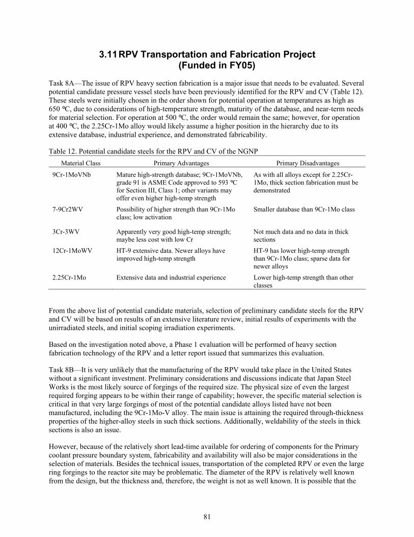
81
3.11 RPV Transportation and Fabrication Project (Funded in FY05)
Task 8A—The issue of RPV heavy section fabrication is a major issue that needs to be evaluated. Several potential candidate pressure vessel steels have been previously identified for the RPV and CV (Table 12). These steels were initially chosen in the order shown for potential operation at temperatures as high as 650 °C, due to considerations of high-temperature strength, maturity of the database, and near-term needs for material selection. For operation at 500 °C, the order would remain the same; however, for operation at 400 °C, the 2.25Cr-1Mo alloy would likely assume a higher position in the hierarchy due to its extensive database, industrial experience, and demonstrated fabricability.
Table 12. Potential candidate steels for the RPV and CV of the NGNP Material Class Primary Advantages Primary Disadvantages
9Cr-1MoVNb Mature high-strength database; 9Cr-1MoVNb, grade 91 is ASME Code approved to 593 °Cfor Section III, Class 1; other variants may offer even higher high-temp strength
As with all alloys except for 2.25Cr-1Mo, thick section fabrication must be demonstrated
7-9Cr2WV Possibility of higher strength than 9Cr-1Mo class; low activation
Smaller database than 9Cr-1Mo class
3Cr-3WV Apparently very good high-temp strength; maybe less cost with low Cr
Not much data and no data in thick sections
12Cr-1MoWV HT-9 extensive data. Newer alloys have improved high-temp strength
HT-9 has lower high-temp strength than 9Cr-1Mo class; sparse data for newer alloys
2.25Cr-1Mo Extensive data and industrial experience Lower high-temp strength than other classes
From the above list of potential candidate materials, selection of preliminary candidate steels for the RPV and CV will be based on results of an extensive literature review, initial results of experiments with the unirradiated steels, and initial scoping irradiation experiments.
Based on the investigation noted above, a Phase 1 evaluation will be performed of heavy section fabrication technology of the RPV and a letter report issued that summarizes this evaluation.
Task 8B—It is very unlikely that the manufacturing of the RPV would take place in the United States without a significant investment. Preliminary considerations and discussions indicate that Japan Steel Works is the most likely source of forgings of the required size. The physical size of even the largest required forging appears to be within their range of capability; however, the specific material selection is critical in that very large forgings of most of the potential candidate alloys listed have not been manufactured, including the 9Cr-1Mo-V alloy. The main issue is attaining the required through-thickness properties of the higher-alloy steels in such thick sections. Additionally, weldability of the steels in thick sections is also an issue.
However, because of the relatively short lead-time available for ordering of components for the Primary coolant pressure boundary system, fabricability and availability will also be major considerations in the selection of materials. Besides the technical issues, transportation of the completed RPV or even the large ring forgings to the reactor site may be problematic. The diameter of the RPV is relatively well known from the design, but the thickness and, therefore, the weight is not as well known. It is possible that the

82
RPV will require field fabrication, meaning welding of the ring forgings, heads, etc. onsite. In this case, the conduct of Post Weld Heat Treatment (PWHT) takes on more significance in that a PWHT is more difficult to conduct and control than that performed in the shop environment. Additionally, since the flange forging is likely to be the limiting forging component of the RPV, the option of eliminating the flanged closure and instead designing for cutting and rewelding the RPV if access is required may be a valid consideration. This issue has not been addressed at this point, but may be addressed in future revisions.
Fabrication and transportation for the RPV ring forgings are critical issues to be included within the literature review. This review will enlist the assistance of consultants with expertise in large vessel fabrication, particularly with low alloy and medium level chromium ferritic steels. As mentioned earlier, there currently is no domestic manufacturer that can supply the very large ring forgings that are needed for the RPV. Japan Steel Works) appears to have the capacity to produce forgings of the needed size, but there may be other fabricators as well. Fabrication of the RPV with rolled and formed plates joined with longitudinal welds will remain an option, but is not desirable because it results in a significant increase in weldments in the beltline region, the most highly irradiated region, of the RPV. If high chrome low alloy steels are retained as the prime candidate materials, fabrication, heavy-section welding and PWHT will require development. The production of such forgings with the potential candidate alloys will be evaluated during the literature review.
The assessment will also include transportation of individual ring forgings or a partially completed RPV to the United States, and a fully completed RPV to the construction site in Idaho. The assessment will include evaluation of domestic welding and heat-treating capabilities for the potential case of final fabrication of the RPV in the United States and transport of the completed RPV to the construction site. Transportation of other than a fully completed RPV to the construction site will also entail assessment of field fabrication issues and capabilities.
3.11.1 Additional Developmental Tasks not Funded in FY-05
The initial purchase of welding consumables will be based on the results of the literature review and preliminary materials selection documents. This test program will include enough materials to ensure the capability to fabricate weldments of sufficient size to enable machining of the numbers of mechanical test specimens needed for inclusion in the baseline, aging, and irradiation tasks. Additionally, development of welding techniques and processes, to include PWHT schedules, will be included in the program for those preliminary candidate materials for which a mature welding technology does not exist.
In addition to the evaluation of weld metals and Heat Affected Zone for the preliminary candidate materials,
Field fabrication of any part of the RPV involving welding will likely require development of a PWHT procedure and evaluation of the procedure and the weldments must be included in the testing program. Following identification of fabricators deemed to have the capability for manufacture of the required ring forgings, a fabricator will be chosen to fabricate a forging of sufficient size to represent the largest and thickest one required for the RPV. This forging would be evaluated with mechanical testing and microstructural characterization. As a part of this task, a review of non-destructive examination (NDE) procedures for the preliminary candidate materials will be conducted. If the review indicates the need for development of procedures specific to those materials, NDE procedures will be developed with a view towards satisfying the requirements of the ASME Code and the NRC, to include incorporation of the procedures in the required in-service inspection program.

83
3.12 Reactor Pressure Vessel Emissivity (Not funded in FY05)
Emissivity data on the various potential candidate materials for the RPV are needed. This is necessary because cooling of the RPV occurs partially by radiation from the outer surface to the air in the cavity between the RPV and surrounding concrete. Further, the pressure vessel must be able to radiate sufficient heat during any anticipated accident conditions throughout the life of the reactor. It is therefore necessary to have a stable, high emissivity surface on the external surface of the pressure vessel at elevated temperatures. Depending on the emissivity of the selected material, it may be necessary to incorporate a high emissivity coating on the outer surface of the RPV. Early testing to establish limitations of potential candidate materials emissivity and the performance and durability of proposed surface modifications to improve emissivity must be performed early to provide design feedback and limitations. Preliminary emissivity screening testing of the potential candidate materials will be performed to determine the detailed experimental program needed for developing a stable surface with minimum emissivity required for adequate cooling of the RPV. Concurrent with that testing, a surface treatment/coatings program will be conducted to investigate the efficacy of various potential concepts for either increasing the emissivity of the RPV materials or providing a coating that would have the required emissivity. If the tests of the potential candidate materials indicate a high probability that the materials will have sufficiently high emissivity under operating conditions, a special coatings development program will not be required.
3.13 Internals Project (Not funded in FY05)
The first step in the research program on materials for the metallic reactor internals will be a comprehensive and detailed review of the potential candidate alloys identified in Table 6. The existing database for those alloys will be assembled, analyzed, and evaluated with respect to the design and operating requirements described above. Principal topics for review will include: high-temperature strength, stability, and long-time performance under irradiation of the materials, effects of helium typical of gas reactor coolant on the mechanical and physical properties of the materials, codification status, prospects, and needs, including maturity and limitations of the CV for each material selected. The status of the joining technology will be reviewed. The weld metal and weldment database will be collected for the candidate alloys. The technology behind the weld strength factors under development by the ASME and other international codes will be reviewed in collaboration with activities on design methodology. The neutron fluences accumulated in the metallic core internal materials are expected to be low relative to the tolerances of the structural alloys. Nevertheless, these will be reviewed and details developed for confirmatory testing and evaluation. Based upon the results of the review, details of the program to evaluate the mechanical and fracture properties of the leading candidates, along with their environmental and irradiation response will be developed. Major anticipated research activities are provided below.
Joining technology will be developed and experimental work started. Weldments will be produced for mechanical testing, aging studies, and microstructural characterization. Creep-rupture and creep crack growth testing will be started. Environmental testing and creep-fatigue will be performed and computational models will be used to predict weld microstructures. Microstructural evaluations will be completed on aged materials. Microstructural parameters will be quantified for use in damage prediction models. Preliminary estimates of weld strength reduction factors will be made. Candidate weld metals will be ranked on the performance. Data will be provided to the design methodology activity to explore the constitutive behavior of weld metal relative to base metal. Weldment test data required for the efforts on design methodology will be produced and testing of welds will establish confidence in the modeling efforts and the code rules developed from testing and modeling.

84
3.14 Intermediate Heat Exchanger and Piping Fabrication Test (Not Funded in FY05)
A detailed assessment of the materials requirements for heat exchanger designs will be undertaken prior to any experimental work. The leading potential candidate alloys will be identified in the course of this assessment. Most likely, these materials will be Alloy 617, Alloy XR, and Alloy X. New alloys such as CCA617, Alloy 740, and Alloy 230 will be considered as alternates. An assessment will be undertaken of the potential of Cf/C composites for the compact IHX.
The baseline materials data generation program for the IHX will focus on the characterization of the material of construction as it is influenced by the specific fabrication procedures needed to produce the compact IHX configuration. The material performance requirements will be developed and a list of leading candidates will be identified. It will be necessary to decide if the fabrication processes should be selected to produce a material of optimum metallurgical condition or if an off-optimum material condition is satisfactory. At 1000 °C, most of the wrought nickel base alloys require relatively coarse grain size for good creep strength but fatigue resistance is best for fine grain size.
Exploratory testing will be undertaken to establish the effect of fabrication variables on the subsequent creep and fatigue properties. Materials of comparable chemistry, grain size, and processing history will be used to produce data, which can then be used to model the performance of the IHX.
It will be determined if the metallurgical state of materials included in the testing program for the core supports and internals are suitable for the IHX. If so, a mechanical testing and aging work on materials for the IHX will not be needed. Bench testing small models of the IHX will be performed to add confidence to life prediction methodologies. Metallurgical evaluations will be undertaken.
Manufacturing issues related to the compact counter-flow IHX will be addressed as part of the research and testing activities. It has yet to be demonstrated that such a unit can be manufactured from the high-temperatures alloys that are the leading candidates, so it is clear that the manufacturing of such a unit will produce several issues to be resolved. Issues include the production of a high-integrity diffusion bond between the sheets of metal used to build the module, the control of conditions that result in an optimum grain size in the metal ligament, the development of methods for NDE of the unit, and the design and fabrication of joints between the unit and the inlet and outlet piping systems.
A part of the development of the fabrication technology for the IHX, the interfaces of the bonded plates will be metallurgically and mechanically evaluated. The specific mechanical tests will be determined after completion of exploratory testing.
A research effort that helps to develop the fabrication technology will be undertaken, and a testing plan will be developed to examine the performance of the configuration under various loading conditions. Included in the testing will be thermal transients.
A review will be undertaken of German and Japanese experiences with materials in “more conventional” IHX units for gas-cooled reactors. Any materials technology needed to advance the conventional units will be identified after this review.

85
3.15 Hot Duct Liner and Insulations Test (Not funded in FY05)
Data on the performance of fibrous insulation are needed to ensure that the selected materials are capable of lasting for the life of the plant. The data include: physical properties (heat resistance, heat conductivity and heat capacity), long-term thermal and compositional stability, mechanical strength at temperature, resistance to pressure drop, vibrations and acoustic loads, radiation resistance, corrosion resistance to moisture and air-helium mixtures, stability to dust release and gas release, thermal creep, and manufacturing tolerances and mounting characteristics. The acquisition of these data requires testing of insulation specimens or small assemblies of thermal insulation panels and application of appropriate ASTM standards. This standards development work will be supported within this program. Moreover, application of current non-destructive evaluation techniques, especially in support of the monolithic insulators, is included within this test plan. Specific test rigs and facility requirements include helium flow, vibration, and acoustic test equipment as well as an irradiation facility and hot cell. Prototype assemblies testing is not planned to include neutron irradiation. However, this decision will be made following the neutron and gamma irradiation testing.
3.16 Valves, Bearings, and Seals Qualification Test (Not funded in FY05)
The qualification test program for these materials will be added with a later revision of this Program Plan. There is insufficient design information to support such a program at this time.
3.17 Management and Administration Tasks (Funded in FY05)
The NGNP Materials R&D Program Manager is responsible for performing technical and programmatic activities including program management, project administration, progress tracking support and working with the SIM and the NTD for Materials to ensure integration of tasks with the overall NGNP Project and related materials activities. These tasks include program plan development, work package and schedule coordination, interface with program control activities, coordination of technical reviews and development of communication products. This support covers secretarial, travel, project management reserve, miscellaneous expenses, procurement support, and project controls. The Program Manager will also provide support to public and private web sites of the Gen IV International Forum.
The NGNP Program Manager develops and reports the R&D plans, material requirements and qualification plans. Concurrence will occur on scope, schedule and estimated cost with the SIM and the NTD for Materials.
The Program Manager supports the MRC’s work in providing independent assessment of the NGNP Materials R&D Program. The Program Manager identifies ASME and ASTM committees that need to be supported for efforts in developing codes and standards. All procurements and test methods will be reviewed and approved by the Program Manager.
The program performance is measured by incorporating the input from the approved work packages to develop a performance baseline for each fiscal year. Each month the work package managers will determine the percent complete of planned work and the status of reportable milestones. This will be used to calculate the earned value of the work completed for the month. Performance metrics, cost performance index and schedule performance index, shall be calculated as well as an estimate at

86
completion. The Program Manager will identify reasons for out of norm performance and if necessary undertake corrective actions to return the work to within acceptable bounds.

87
4 DELIVERABLES AND MILESTONES
The deliverables listed are for FY2005. The deliverables for follow-on years will be documented in the next revision of the NGNP Materials R&D Program Plan. The deliverables and milestones with an I and O designation are for the INL and the ORNL, respectively.
4.1 Graphite
Deliverable: D1O1 Submit letter report describing the procurement of representative lots of candidate materials.
3/30/2005
Deliverable: D1O2 Issue irradiated graphite post irradiated examination report 9/30/2005
Deliverable: D1O3 Issue ATR creep experimental plan 9/30/2005
Deliverable: D1O4 Develop draft standard test method and submit for approval to ASTM D02-F committee
9/30/2005
Deliverable: D1O5 Issue a progress report on the modeling effort 9/30/2005
Deliverable: D1O6 Issue a preliminary capsule design and experimental plan (D1I3)
9/30/2005
Milestone: M1O1 Submit post irradiation examination report to DOE 9/30/2005
Milestone: M1O2 Submit ATR creep experimental plan to DOE 9/30/2005
Deliverable: D1I1 Finalize graphite selection strategy 2/30/2005
Deliverable: D1I2 Issue letter report summarizing INL support of the ORNL purchase of graphite (D1O1)
3/30/2005
Deliverable: 1I3 Issue ATR creep experiment capsule design report (D1O6) 9/30/2005
Deliverable: 1I4 Complete round robin testing using the modified standard 3/30/2005
Milestone: M1I1 Submit ATR creep experiment capsule design report to DOE 9/30/2005
4.2 HDTM
Deliverable: D2O1 Issue report summarizing existing Alloy 617 database 9/30/2005
Deliverable: D2O2 Develop controlled material specification for Alloy 617 for nuclear applications
4/30/2005
Deliverable D2O3 Issue procurement documents for material for testing purposes 7/30/2005
Deliverable D2O4 Issue letter report summarizing results of initial scoping tests for creep and stress- strain evolution and status of submittal of Alloy 617 Section III Code Case
9/30/2005

88
Deliverable D5 Issue letter report summarizing results of simplified methods development for very high-temperature alloys
9/30/2005
Milestone: M2O1 Submit report summarizing Alloy 617 database to DOE 9/30/2005
Deliverable: D2I1 Issue procurement documents for Alloy 617 for joint scoping studies
3/30/2005
Deliverable: D2I2 Issue procurement documents for environmental chamber for creep-fatigue test machine, receive chamber, and perform acceptance testing on checkout chamber
4/30/2005
Deliverable: D2I3 Issue a letter report describing the microstructural and strength characteristics of Alloy 617 joints
6/30/2005
Deliverable: D2I4 Issue status report on creep-fatigue testing of specimens with fusion welds in impure helium at temperatures of 800 °C to 1000 °C
9/30/2005
Deliverable: D2I5 Issue status report on 10,000 hour aging at 10000C of inert atmosphere-encapsulated base metal and weldment specimens.
9/30/2005
4.3 Code Support
Deliverable: D3O1 Issue a report on the status of the ASTM D02F Committee 9/30/2005
Deliverable: D3O2 Issue a report on the status of the ASTM Working group on SiC composite testing
9/30/2005
Milestone: M3O1 Submit status report of the ASTM D02F Committee to DOE 9/30/2005
Deliverable: D3I1 Issue a report summarizing ASME Subgroup on Elevated Temperature Design activities
9/30/2005
Deliverable: D3I2 Issue a report summarizing ASME Task Group on Graphite Core activities
9/30/2005
Deliverable: D3I3 Complete series of meetings and communications with the design community to target composite properties
9/30/2005
4.4 ETTA
Deliverable: D4O1 Issue a white paper on the aging effects on Alloy 617 based on existing data
6/30/2005
Deliverable: D4O2 Issue report that summarizes the assessment of the recommended helium impurity range to be used for testing and the rationale to support the selection of a range.
9/30/2005
Deliverable: D4O3 Issue a status report on the environmental effects of impure helium on Alloy 617 and two other candidate materials using
7/30/205

89
existing data
Deliverable: D4O4 Issue a test plan for long term thermal aging and environmental effects testing of Alloy 617 and other candidate materials
9/30/2005
Milestone: M4O1 Submit report on impure helium to DO 9/30/2005
Deliverable: D4I1 Issue a design and complete construction of a low velocity helium loop with gas clean up capability
7/30/2005
Deliverable: D4I2 Acquire test specimens for long term aging studies 9/30/2005
Deliverable: D4I3 Issue a long term thermal aging and environmental effects testing program plan for Alloy 617 and other candidate materials
9/30/2005
4.5 Irradiation Facility
Deliverable: D5O1 Issue a report on the redesign and fabrication of the hardware that will be used inside the selected reactor for capsule irradiations
9/30/2005
Milestone: M5O1 Submit report on the irradiation facility redesign and hardware fabrication to DOE
9/30/2005
4.6 Composite
Deliverable: D6O1 Issue a report that summarizes the selection of tube architecture and initial infiltration work
6/30/2005
Deliverable: D6O2 Issue a report on the status of irradiation of multi-layer SiCf/SiC and FMI-222 graphite composite bend bar capsules and SiCf/SiC tube specimens.
6/30/2005
Deliverable: D6O3 Issue a report summarizing test plans for failure mode assessment of composite tubes under stress
9/30/2005
Deliverable: D6O4 Issue a report on Cf/C composite vendors 9/30/2005
Deliverable: D6O5 Issue a report on Cf/C candidate materials for control rod applications
9/30/2005
Deliverable: D6I1 Issue a report summarizing modeling and defining potential corrosion effects of SiCf/SiC.
9/30/2005
Deliverable: D6I2 Issue a report summarizing failure mode of composite tubes under stress
9/30/2005
Deliverable: D6I3 Issue a report summarizing composite creep testing 9/30/2005

90
4.7 Database and Handbook
No deliverables in FY05
4.8 PC Turbine and Generator
No deliverables in FY05
4.9 RPV Transport and Fabricability
Deliverable: D9I1 Issue a report summarizing heavy section fabrication technology for the RPV
9/30/2005
Deliverable: D9I2 Issue a report that summarizes transportation and field fabrication issues associated with very large forgings
9/30/2005
4.10 RPV Emissivity
No deliverables in FY05
4.11 Metal Internals
No deliverables in FY05
4.12 Intermediate Heat Exchanger and Piping
No deliverables in FY05
4.13 Intermediate Heat Exchanger Pressure Vessel
No deliverables in FY05
4.14 Hot Duct Liner and Insulation
No deliverables in FY05
4.15 Valves, Bearings and Seal
No deliverables in FY05
4.16 Management
Deliverable: D16I1 Issue Program Plan Rev 2 9/30/2005

91
5 COLLABORATIONS
The primary mechanism for international collaboration for materials R&D activities in support of the VHTR is through the GIF. The GIF is an international effort to advance nuclear energy to meet future energy needs of ten countries–Argentina, Brazil, Canada, France, Japan, the Republic of Korea, the Republic of South Africa, Switzerland, the United Kingdom, and the United States–and the European Union. These partners have agreed on a framework for international cooperation in research for a future generation of nuclear energy systems, known as Generation IV. Generation 1 nuclear reactor systems are considered to be early prototype plants such as Shippingport, Dresden, Fermi I and Magnox. Generation II plants are considered to be the current generation of commercial nuclear plants that are currently producing electricity today. These plants include current PWR, BWR, Canadian Deuterium-Uranium, and AGR plants. Generation III plants are considered to be advanced LWRs and include Advanced Boiling Water Reactors and System 80+ PWR plants. Generation IV plants have not been commercially operated to date and are envisioned to have the following general characteristics: highly economical, enhanced safety, minimal waste and proliferation resistant.
The GIF partners noted above have joined together to develop future generation nuclear energy systems that can be licensed, constructed and operated in a manner that will provide competitively priced and reliable energy products while satisfactorily addressing nuclear safety, waste, proliferation, and public perception concerns. The objective is to have these systems available for international deployment by about 2030 when many of the worlds currently operating nuclear plants will be at or near the end of their operating lifetimes.
Nuclear energy research programs around the world have been developing concepts that could form the basis for Generation IV systems. Many concepts have been developed including the VHTR concepts that include the NGNP. Collaboration on R&D to be undertaken by GIF partners will stimulate progress toward the realization of such systems.
The primary mechanism for collaboration of materials R&D for the VHTR is through the Materials and Components PMB. The minutes of the first meeting of the first meeting of this PMB are given in Appendix B. This board is currently composed of members from France, Switzerland, Japan, Korea, South Africa, the United Kingdom, the United States, and the EU and meets on a nominal quarterly basis in various locations in the world. This board will be addressing each materials R&D program area noted previously and will develop detailed collaboration plans for each of these areas. These plans are being developed in the same approximate order of priority noted in Section 1.3. It is currently envisioned that this process will not be fully developed and implemented until the end of 2006, however, as each plan is developed, implementation of collaboration activities will begin immediately. Currently, the collaboration plan for nuclear graphite R&D is being developed and should be available by April 2005. This will allow further discussion and development of this plan at the next Materials and Components PMB meeting at ORNL scheduled at that time.
It is currently envisioned that collaboration will involve (as a minimum) the establishment of coordinated test and irradiation programs, coordinated purchase of testing materials, coordinated use of specialized testing facilities, coordinated support for the establishment of an integrated Generation IV materials data base and coordinated support of codes and standards committees. Other collaboration areas may be developed as the materials R&D program supported by the board fully matures.
It is expected that these collaboration activities will result in a spirit of cooperation between the participating countries, the acceleration of design and licensing activities of VHTR systems and the reduction of the cost for materials R&D.

92
To make efficient use of program resources, the development of the required databases and methods for their application, it will also be useful to incorporate both the extensive results from historic and ongoing programs in the United States and abroad outside the GIF partnership that address related materials needs. These would include, but not be limited to, DOE, NRC, and industry programs on liquid-metal-, gas-, and light-water-cooled reactor, fossil-energy, space-reactor, and fusion materials research programs.

93
6 PROGRAM COST AND SCHEDULE
6.1 Program Schedule
The NGNP summary program schedule is shown as Figure 20 with a start date of October 2004.
The materials R&D program is designed to deliver materials data and recommendations that will support the NGNP design process. Final materials design data and the final materials selection reports need to be available to complete the preliminary design and are essential at the start of the design to support the initiation of long lead procurements for reactor components.
6.2 Cost and Schedule Estimates
The overall cost for the NGNP Materials R&D Program is estimated to be 212.5 M. The cost estimate for the NGNP material program is broken down by fiscal year and program element in Table 13
Table 13. Summary Cost Major Program
Elements Totals FY04 FY05 FY06 FY07 FY08 FY09 FY10 FY11 FY12 FY13 FY14 FY15
Graphite 36.4 1.6 12.6 7.2 5.5 4.8 4.7 Hi Temp Design Methods 41.4 0.3 1.3 5.3 4.0 8.0 5.4 4.2 4.1 2.2 2.2 2.2 2.2
Code & Standards 4.0 0.5 0.5 0.5 0.5 0.5 0.5 0.5 0.5 Environ Testing & Aging 11.1 0.3 0.7 2.8 2.8 2.8 0.5 0.5 0.5 0.5 RPV Irradiation Facility 2.5 0.5 0.5 0.5 0.5 0.5 Structural Composites 22.1 1.0 3.0 5.0 7.1 4.1 1.9 Database & Handbook 5.0 0.8 0.8 0.8 0.8 0.8 0.8 Turbine & Generator 6.0 1.3 3.1 1.6 RPV Transport & Fab 39.5 0.2 6.5 10.5 10.5 6.5 5.3 RPV Emissivity 0.4 0.2 0.2 Metallic Core Internals 10.3 5.2 5.2 Hot Duct and Insulation 9.9 0.9 3.3 2.7 2.8 0.2 IHX and Piping 8.2 2.0 2.9 1.5 0.8 0.6 0.4IHX Pressure Vessel 2.0 0.3 0.4 0.4 0.3 0.3 0.3Valves, Bearings, Seals 2.5 1.0 1.0 0.5 Administration 11.3 0.4 0.7 1.4 1.7 1.7 1.7 1.7 1.0 0.7 0.5 0.1 0.1Totals 212.5 1.0 6.4 0.0 0.0 0.0 0.0 0.0 0.0 0.0 0.0 0.0 0.0DOE Estimates 201.5 0.7 6.4 29.5 50.8 50.1 36.0 28.0
NGNP Materials Program
05
1015202530354045
FY04 FY05 FY06 FY07 FY08 FY09 FY10 FY11 FY12 FY13 FY14 FY15
Ann
ual B
udge
t

94
Figure 20. Summary Schedule

95
7 REFERENCES
1 Baccaglini, G., et al, Very High Temperature Reactor (VHTR) Survey of Materials Research and Development needs to Support Early Deployment, INEEL/EXT-03-00141, January 31, 2003.
2 Design Features and Technology Uncertainties for the Next Generation Nuclear Plant,INEEL/EXT-04-01816, June 30, 2004
3 Kimball, O. F., and D. E. Plumblee, Gas/Metal Interaction Studies in Simulated HTGR Helium,HTGR -85-064, Schenectady, New York: General Electric Company, June 1985.
4 Natesan, K., A. Purohit, and S. W. Tam, Materials Behavior in HTGR Environments. NURET/CR-6824 and ANL-02/37, Argonne, IL: Argonne National Laboratory, July 2003
5 Prediction of the Long-Term Behavior of Materials, Including Waste Forms, Used in Engineered Barrier Systems (EBS) for Geological Disposal of High Level Radioactive Waste, 1997.
6 Shenoy, A., Gas Turbine-Modular Helium Reactor (GT-MHR) Conceptual Design Description Report, Rev 1, GA-910720, July 1996
7 NGNP Point Design Results of the Initial Neutronics and Thermal Hydraulic Assessments During FY-03, Rev. 1, INEEL/EXT-03-00870, September 2003
8 ASME Code Case 2063-3, Ni-22Cr-14W-2Mo-La Alloy (UNS N06230) Section I and Section VIII, Division 1, Approval Date: August 08, 1994
9 Richards, M., Shenoy, A., Kiso, Y., Tsuji, N., Kodochigov, N., and Shepelev, S., Thermal Hydraulic Design of a Modular Helium Reactor Core Operating at 1000 °C Coolant Outlet Temperature,NUTHOS-6 #00350, Oct, 2004
10 DOE Orientation Presentation, Pebble Bed Modular Reactor, August 7, 2003
11 Very High Temperature Reactor Survey of Materials Research and Development Needs to Support Early Deployment, Gen IV Nuclear Energy Systems: INEEL, January 27, 2003, p. 19
12 Shenoy, A., High Temperature Materials, ANS 2003 Gas Reactor Technology Course Presentation
13 Ion, S., D. Nicholls, R. Matzie, and D. Matzner, Pebble Bed Modular Reactor, The First Generation IV Reactor To Be Constructed, World Nuclear Association Annual Symposium, London, UK, September 3-5, 2003
14 Matzner, D., PBMR Reactor Presentation to the Independent Technical Review Group (ITRG),INEEL, February 2004
15 ASME, Specification for Quenched and Tempered Vacuum Treated Carbon and Alloy Steel Forgings for Pressure Vessels, ASME SA508
16 ASME, Specification for Pressure Vessel Plates, Alloy Steel, Quenched and Tempered, Manganese-Molybdenum and Manganese-Molybedenum-Nickel, ASME SA533

96
17 Matzie, Dr. R., PBMR Board of Directors / Westinghouse Senior VP, U.S. Department of Energy Orientation Seminar on Pebble Bed Modular Reactor, August 7, 2003
18 Inagaki, Y, et al., Nuclear Engineering and Design, Vol. 185, 1998, pp. 141-151
19 Shah, V. N., S. Majumdar, and K. Natesan, Review and Assessment of Codes and Procedures for HTGR Components, NUREG/CR-6816 (ANL-02/36), Argonne National Laboratory, June 2003
20 Corum, J. M., and J. J. Blass, “Rules for Design of Alloy 617 Nuclear Components to Very High Temperatures,” Fatigue, Fracture, and Risk, PVP-Vol. 215, ASME, 1991, pp. 147-153
21 ASME Code Case 2359-1, Ni-25Cr-9.5Fe-2.1Al(UNS N06025) Section I and Section VIII, Division 1, Approval date: January 27,2003
22 Very High Temperature Reactor Survey of Materials Research and Development Needs to Support Early Deployment, Gen IV Nuclear energy Systems, INEEL, January 27, 2003
23 Cannon, W. R., and T. G. Langdon, “Review of Creep of ceramics – Part 1 Mechanical Characteristics”, Journal of Materials Science 18 (1983) pp. 1-50.
24 Lessing, P. A., and R. S. Gordon, “Creep of polycrystalline alumina, pure and doped with transition metal impurities”, Journal of Materials Science 12 (1977) pp. 2291-2302.
25 Lessing, P. A., R. S. Gordon, and K. S. Mazdiyasni, "Creep of Polycrystalline Mullite", J. Am. Cer. Soc. 58 [3-4] (1975) pp.149.
26 Grafoil is a registered trademark of UCAR Carbon Company, Inc., P.O. Box 218, Columbia, TN 38402-0218. Phone: 931-380-4360.
27 Kaowool is a registered trademark of Thermal Ceramics (Division of Morgan Refractories), Old Savannah Rd., P.O. Box 923, Augusta, GA 30903. Phone: 706-796-4323.
28 Calcarb, 110 Indel Ave., P.O. Box 477, Rancocas, NJ 08073. Phone: 800-732-5432.
29 Jones, R.L., “Corrosion Experience in U.S. Light Water Reactors – A NACE 50th Anniversary Perspective”, in Corrosion 93, NACE International, Houston, TX, 1993.

97
Appendix A
NGNP Materials Review Committee Meeting

98
This page intentionally left blank.
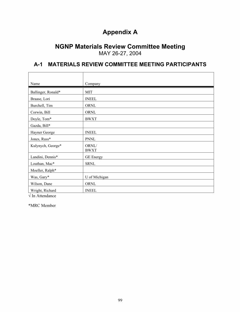
99
Appendix A
NGNP Materials Review Committee Meeting MAY 26-27, 2004
A-1 MATERIALS REVIEW COMMITTEE MEETING PARTICIPANTS
Name Company
Ballinger, Ronald* MIT
Braase, Lori INEEL
Burchell, Tim ORNL
Corwin, Bill ORNL
Doyle, Tom* BWXT
Gazda, Bill*
Hayner George INEEL
Jones, Russ* PNNL
Kulynych, George* ORNL/ BWXT
Landini, Dennis* GE Energy
Louthan, Mac* SRNL
Moeller, Ralph*
Was, Gary* U of Michigan
Wilson, Dane ORNL
Wright, Richard INEEL In Attendance
*MRC Member

100
A-2 MRC MEETING MAY 26, 2004
A-2.1 Overview of the NGNP Materials R&D Program
Table A-1. Overview of the top issues from the MRC review of the NGNP Selection and Qualification Program Plan
# Comment MRC Direction
2 The test program does not mention the need to evaluate thru thickness properties of thick sections of pressure vessel steels. I believe thru thickness properties are important and need to be addressed.
This should be included in Revision 1: Focus on the abnormal aspects of microstructure. The reality test is how this would be done relative to commercial practices.
3 Graphite program does not mention high temperature tribology properties of graphite, which could be an issue with regards to the need for wear resistant coatings at control rod channels.
This is an issue for control rod guide tube insertion and for pebble bed movement where there is dynamic behavior. There was dust generated in the Fort St. Vrain (FSV) reactor core. There is a high velocity test program.
13 The third paragraph of 3.4.4.2 points out the importance of the 1980’s code case for Alloy 617. The author suggests that this code case could be used as a “springboard” for approval of alloy 617. The following are recommended:
No. 13a: Select a group of ASME B&PV Code experts to form a committee to plan and oversee all code activities for the NGNP project. Approval of ceramics may or may fall under this committee.
No. 13b: Select the 1980’s code case for Alloy 617 (982 C) as an initial draft code case for seeking approval at 1000 C.
No. 13c: Complete the actions required and spelled out in 3.4.4.2 p. 79. No. 13d: Contact the appropriate ASME committee chairman.
No. 13e: Set a date with the appropriate ASME committee’s for the initial contact to be no later than first quarter 2004.
We can find the perfect metallic material for these applications, but if we don’t get ASME approval, then we can’t use it. Much effort and time was spent on qualification of Inconel-617 up to 980 °C. This needs to be revisited. Karen Moore went to the NH committee and became a part of the committee. We need to make a presentation to the Executive Committee of ASME. It is important to get them on-board from the beginning of the code work to expedite the process. We need support from the metal companies. This is a huge issue. The September 4, 1974 document from Ralph Moeller, discussed Inconel 617. Logistics Discussion: The MRC will get into discussions on alloys. The selection process will be an interactive process over a period of time determined by the program. The program will dictate the alloy selection process and what design the private consortium chooses. How do you draw in the producers or the people to develop these tests for a product they may not sell for many years? This is also an issue for ASTM with graphite qualification. The metal producers will likely support this effort. They are very interested in metals code approval. We need to work together with the metals industry to move forward. This is early action. The actions listed in 3.4, Nov 7, report should be top priority. These should be brought forward in Rev 1. Need to look at how to do this for the composites. To start the code case, we need to know the metal.
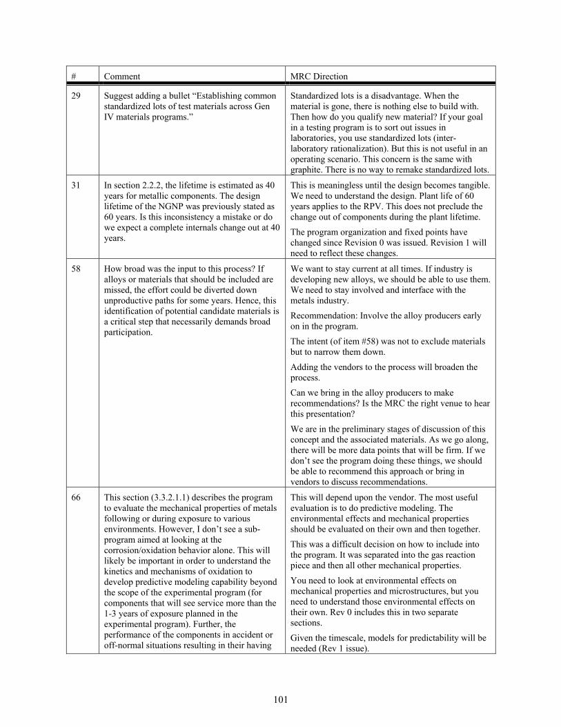
101
# Comment MRC Direction
29 Suggest adding a bullet “Establishing common standardized lots of test materials across Gen IV materials programs.”
Standardized lots is a disadvantage. When the material is gone, there is nothing else to build with. Then how do you qualify new material? If your goal in a testing program is to sort out issues in laboratories, you use standardized lots (inter-laboratory rationalization). But this is not useful in an operating scenario. This concern is the same with graphite. There is no way to remake standardized lots.
31 In section 2.2.2, the lifetime is estimated as 40 years for metallic components. The design lifetime of the NGNP was previously stated as 60 years. Is this inconsistency a mistake or do we expect a complete internals change out at 40 years.
This is meaningless until the design becomes tangible. We need to understand the design. Plant life of 60 years applies to the RPV. This does not preclude the change out of components during the plant lifetime.
The program organization and fixed points have changed since Revision 0 was issued. Revision 1 will need to reflect these changes.
58 How broad was the input to this process? If alloys or materials that should be included are missed, the effort could be diverted down unproductive paths for some years. Hence, this identification of potential candidate materials is a critical step that necessarily demands broad participation.
We want to stay current at all times. If industry is developing new alloys, we should be able to use them. We need to stay involved and interface with the metals industry. Recommendation: Involve the alloy producers early on in the program.
The intent (of item #58) was not to exclude materials but to narrow them down.
Adding the vendors to the process will broaden the process. Can we bring in the alloy producers to make recommendations? Is the MRC the right venue to hear this presentation?
We are in the preliminary stages of discussion of this concept and the associated materials. As we go along, there will be more data points that will be firm. If we don’t see the program doing these things, we should be able to recommend this approach or bring in vendors to discuss recommendations.
66 This section (3.3.2.1.1) describes the program to evaluate the mechanical properties of metals following or during exposure to various environments. However, I don’t see a sub-program aimed at looking at the corrosion/oxidation behavior alone. This will likely be important in order to understand the kinetics and mechanisms of oxidation to develop predictive modeling capability beyond the scope of the experimental program (for components that will see service more than the 1-3 years of exposure planned in the experimental program). Further, the performance of the components in accident or off-normal situations resulting in their having
This will depend upon the vendor. The most useful evaluation is to do predictive modeling. The environmental effects and mechanical properties should be evaluated on their own and then together.
This was a difficult decision on how to include into the program. It was separated into the gas reaction piece and then all other mechanical properties. You need to look at environmental effects on mechanical properties and microstructures, but you need to understand those environmental effects on their own. Rev 0 includes this in two separate sections.
Given the timescale, models for predictability will be needed (Rev 1 issue).

102
# Comment MRC Direction previously undergone substantial oxidation (e.g., 10-30 years) will be very important.
76 Many of the components (such as attachments, insulation, seals, instruments, etc) to be developed for the NGNP will depend upon prototype testing to verify performance under reactor conditions. It is not clear how the interface with the NRC will be handled to assure that the testing program will meet the requirements for NRC licensing.
We had an initial meeting with the NRC technical staff at ORNL. We thought this would lead to further meetings. Currently, the NRC has decided not to input to the issues because they do not feel comfortable with the approach DOE is taking. They have been told to stand down with the NGNP program. They are not engaged at this time due to high-level disagreements between NRC commissioners and DOE. There is a lack of definition and approach being taken on this program. This issue will make a difference in code development work. ORNL currently participates on the ASME committee. It will help to have NRC participation on the code committee. Note: the PBMR committee is about to make a licensing application with the NRC. Their involvement may change the way NRC participates.
The MRC could make a recommendation that the NRC participate on the committee. Once DOE determines the vendor consortium, NRC should start to participate actively.
78 The integration of the Materials Program with the System Design and the other System/Component Development program is not apparent. How is the Materials Program to be integrated into the design program to optimize the overall program, especially where component testing is required to demonstrate acceptability?
Vendor selection should resolve this issue. We are operating in a pre-vendor mode.
82 An additional primary factor for reactor materials (especially reactor internal components) is the interaction with the other components and stress loading. Relative motion, friction, vibrations, thermal cycling, etc are equally important in the materials selection process to avoid failure and generation of loose parts or debris.
This is a statement.
105 The two milestones under fabrication technology program should really be Cf/C and SiCf/SiC large-scale composite validation. Also, the assessment and assistance time scales for fabrication infrastructure are much too short. The first two should run through early 05 and the later through 06.
Assistance time scales are the Gantt charts.

103
A-2.2 Discussion of Materials R&D Issues
Table A-2. Recommended Priority For NGNP Program Plan, Revision 1 Recommended Tasks – Not Design Specific
# Activity Discussion Short-Term
FY-05Longer-Term
FY-06 and Beyond
1. Develop and qualify core graphite materials.
Need to qualify the materials to link them to the previous materials. PBMR: applies to the moderator. The graphite selected is the development of existing materials. Vendor developing PBMRs have data from the prior German work and from the UK data. They have designed into the reactor the ability to replace key parts of the reflector. PBMR has not licensed this design with the NRC. Prismatic Block: Fuel graphite The US choice for graphite is significantly different from the PBMR graphite. We are not prepared to make the same statement as PBMR. This is an appropriate National Lab Activity. At this stage, this is research that is not reactor design specific. Strategy for 05 to start the process of purchasing of graphite for future tests at a sufficient quantity. Do we consider more than one graphite? Need to talk to the suppliers to identify the costs of procurement and to discuss the strategy of the number of materials that should be included in the strategy. Need a database of graphite. Evaluation should be broad enough to gather graphite data for later down select. There are three graphites that PBMR have available. What can we advise the graphite company to keep replicating the graphite for continued use.
Develop a strategy to review the 3 potential graphites. Initiate the purchase of graphite at a sufficient quantity for testing. Start the design of radiation creep experiments. Complete PIE of bend bar samples at ORNL. (NGB-10 graphite) Review applicable GIF country’s plans for irradiation experiments (5FP & 6FP).
Develop relationship between constituent raw materials and graphite irradiation behavior for the manufacturing of graphites. Develop a database for graphite that can link back to historical data for the 3 candidates.

104
Recommended Tasks – Not Design Specific
# Activity Discussion Short-Term
FY-05Longer-Term
FY-06 and Beyond
2a. Development of improved high temperature design methodology.
Must be done regardless of reactor design.
Includes the IHX, RPV, pressure boundary, and internal metallics.
It is very important that all of these activities are coordinated and communicated. ASME Code Committee only meets four times a year. Need to develop the coordination strategy.
Funding for this activity is important. Section 3.4, Rev 0, does a good job outlining the issues, but we need a strategy and action plan to implement this section. There is a lack of data on 617 joints, relative to fusion bonding. There is an ORNL program on 617 under the fossil program and INEEL is doing some work on wrought material under a different program.
Continue to support the on-going activities for design methodology and constitutive equation development.
Continue to support the integration of the draft Code Case (subsection NH) for 617.
Creep fatigue testing on joints (e.g., Alloy 617) (based on indirect cycle with IHX). Supports code case and IHX development.
Complete the necessary activities to meet the project goals.
2b. Expansion of the ASME Code and ASTM standards.
Must be done regardless of reactor design. RPV is included here. This is critical to having a licensed graphite reactor. There is no ASME code that defines how to construct the core support structure with graphite. Currently in progress with ASME. This is applicable to any reactor program. We should qualify under ASME Section II to allow it to be used under Section III. There is no specific code that specifically covers the prismatic core fuel graphite. Metallic and graphite.
Develop a strategy and action plan to implement Section 3.4, Rev 0, page 75. (NGNP Materials Selection and Qualification Program Plan). Implement the strategy ASAP in FY-05.Initiate the development and round-robin tests for ASTM fracture toughness standard for graphite. Evaluate the ceramic matrix composite standards for applicability to Cf/Ccomposites. Look at mil-spec standards for Cf/C.
Complete the necessary activities to meet the project goals.

105
Recommended Tasks – Not Design Specific
# Activity Discussion Short-Term
FY-05Longer-Term
FY-06 and Beyond
3. Thermal aging effects and environmental degradation processes.
Applies to IHX, RPV, pressure boundary, and internal metallics.
Includes, base metal, heat effects, and fusion.
There are no thermal aging effects for Cf/C composites at NGNP relevant temperatures. There are degradation issues. Thermal stability of SiCf/SiC is unknown.
Need to know the right range (boundary) to study.
Should include some stress specimens.
Evaluate existing documentation on lack of thermal aging on graphite and Cf/Ccomposites.
Evaluate existing documentation and develop a strategy on thermal aging experiments on metals.
Evaluate existing documentation on environmental effects on microstructure evolution.
Research on metals and SiCf/SiCcomposites to raise temperature envelope for microstructure and microchemical stability.
Research on environmental degradation on metals, SiCf/SiCcomposites, and Cf/C composites.
Long-term effects of impurities from air and water on graphite properties.
Kinetics data for accident scenarios.
4. Long-term irradiation effects on mechanical properties at elevated temperature.
RPV is included here. May want to look at RPV metal alloys first. We should include some stressed samples. No one has done radiation creep experiments on Cf/C composites. The response of the composite material in a radiation environment is material process and design dependent. Radiation creep is an unknown in SiCf/SiC composites, but some evidence suggests it will be an issue. It is design dependent. Low flux irradiation facility is needed to provide data for the RPV. (UofM low fluence reactor is no longer available.) The NRC need is now (low flux data). This is tied to the 2¼ Cr-1Mo extension. The MRC recognizes the need for this data, but there is not enough information available to make a recommendation for NGNP. We recognize that efforts are
Develop a strategy to obtain irradiation test space necessary to meet project goals.
Research on the higher chromium alloys (2 ¼ and 9 Chrome). Conduct research as designs develop.

106
Recommended Tasks – Not Design Specific
# Activity Discussion Short-Term
FY-05Longer-Term
FY-06 and Beyond underway.
5. Development and certification of composites and ceramics for reactor service.
Ceramics include insulation and support structures, which do not have the same generic nature. Prismatic: Layer of monolithic ceramic support material. Issue: some ceramics can be very large structures.These materials have to be part of an irradiation program and fairly specific for licensing program. This can be complicated without the plant design. Composites: Need to try to understand who can make the components that these reactor systems will need. R&D on composites for the support structure is a generic reactor issue. This would be a good generic research area. How big of a Cf/C structure can be made (re: dome and guide tubes)? How is it joined and supported?
PBMR is planning on using Alloy 800 H for their guide tubes, with limits on their temperatures.
Insulation: Fibrous insulating materials. There is an insulation pack in the top head. Need to ensure there are no compatibility issues. (Design specific) Are there stability issues with thermal radiation affects?
Is there a database for insulating composites?
Fundamental data involves thermal conductivity and mechanical issues of how it is attached.
How you attach a clad around a block of material. This is not generic research.
Review vendor capabilities for SiCf/SiC and Cf/Cand how big and/or complex of a component that can be produced. (White paper). Review and evaluate existing data on the behavior of composites in a tubular geometry.
Evaluateproduction and properties of Cf/Cand SiCf/SiC guide tubes.
Determine the need for Cf/C tubular testing in ASME. Are they valid under the SiCf/SiC standard? (Part of the expansion of ASME Code section, see #3)
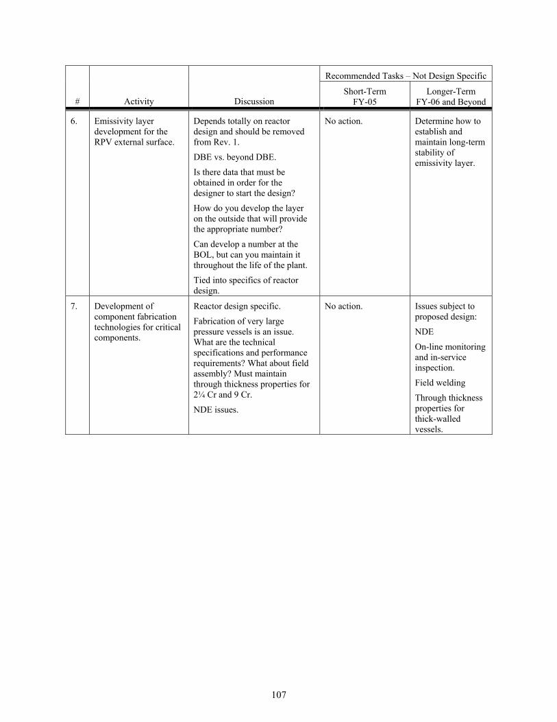
107
Recommended Tasks – Not Design Specific
# Activity Discussion Short-Term
FY-05Longer-Term
FY-06 and Beyond
6. Emissivity layer development for the RPV external surface.
Depends totally on reactor design and should be removed from Rev. 1.
DBE vs. beyond DBE.
Is there data that must be obtained in order for the designer to start the design?
How do you develop the layer on the outside that will provide the appropriate number?
Can develop a number at the BOL, but can you maintain it throughout the life of the plant. Tied into specifics of reactor design.
No action. Determine how to establish and maintain long-term stability of emissivity layer.
7. Development of component fabrication technologies for critical components.
Reactor design specific.
Fabrication of very large pressure vessels is an issue. What are the technical specifications and performance requirements? What about field assembly? Must maintain through thickness properties for 2¼ Cr and 9 Cr.
NDE issues.
No action. Issues subject to proposed design:
NDE
On-line monitoring and in-service inspection.
Field welding
Through thickness properties for thick-walled vessels.

108
A-3 MEETING DISCUSSION May 27, 2004
Determine the General Direction for the NGNP Program Plan, Rev. 1
Expand the performance envelop:
- Temperature environments
- Performance of the work proposed
- Ability to use Inconel-617 at temperatures above 950 °C (table 3.2, Rev. 0)
- Ability to use other materials for a longer period of time.
Materials program is critical to the success of the NGNP program. Licensing of the plant will require a lot of materials information to support the current operating conditions. It is naïve to assume that this responsibility can fall on the shoulders of the contractors. Vendors use enabling technologies critical to the development, they do not develop them. Materials data must stand the test of review.
Critical/enabling technologies are needed to produce an NGNP beyond certain conditions and are developed by national labs, not vendors.
Endorse the Gen IV concept, but DOE must have the infrastructure to have a viable program to support the enabling technologies.
It is obvious that this program is under funded.
Issue: There appears to be no strong advocacy for the NGNP Materials R&D Program.
The credibility of the NGNP program needs to be firmly established.
- Narrow down choices
- Input from George Kulynych
The NGNP program is still evolving and so the recommendations are based on the generic materials issues for HTGRs operating in the range of outlet temperatures approaching 1000 °C.
The MRC recommends that the NGNP program place near-term emphasis on selected technical areas which advance the overall high temperature reactor technology including:
- High temperature graphite materials.
- High temperature design methodology.
- Expansion of ASME code and ASTM standards.
- Thermal aging and environmental degradation effects of potential HTR materials.
- Long-term irradiation effects on mechanical properties at elevated temperatures.
- Development and certification of components and ceramics for HTR services.
Encourage the integration/coordination of international R&D on HTR materials with the NGNP Materials R&D Program to optimize efforts.

109
Logistics:
- Send the NGNP website password and instructions to the MRC.
- Collect schedule information from MRC participants for potential next meeting dates and locations during the first quarter of FY-05.
- Ensure the objective for holding another meeting is sufficient.
- Locations: Chicago, Atlanta, Florida, Oak Ridge, Boston, Cincinnati
- Send expense reports to Lori Braase.

110
This page intentionally left blank.
-

111
Appendix B
GIF VHTR Materials and ComponentsProvisional Project Management Board Meeting

112
This page intentionally left blank.

113
Appendix B
GIF VHTR Materials and ComponentsProvisional Project Management Board Meeting
MAY 4-6, 2004
Idaho Falls, Idaho
B-1 INTRODUCTION
The Materials and Components provisional PMB for the GIF VHTR program met in Idaho Falls, Idaho on May 4-6, 2004. The purpose of the meeting was to discuss R&D needs and collaboration opportunities associated with materials related to the VHTR and the NGNP, the United States demonstration reactor.
Some of the R&D issues discussed during the meeting included:
1. Materials issues associated with the NGNP RPV.
2. High temperature metallic materials and coatings (internals and structural materials, IHX and turbine).
3. Core non-metallic materials (graphite, composites and ceramics).
4. Corrosion in high temperature helium.
5. Codification and modeling issues related to selected metallic alloys, graphite, and composites.
6. Components development.
In addition, the provisional PMB discussed and addressed the GIF Experts Group comments (December 2003) related to the Materials and Components section in the VHTR R&D Plan.
The next meeting of the VHTR Materials and Components provisional PMB is tentatively scheduled for September 7-8 or 20-21, 2004, in Manchester, UK.

114
B-2 AGENDA
Tuesday, May 4, EROB-350
0730 Introductions, Opening Remarks and Objectives- G. Hayner, INEEL/P. MacDonald, INEEL/W. Corwin, ORNL
0830 Summary of Meeting Objectives and NGNP History- P. Billot, CEA/ W. Hoffelner, PSI
0900 NGNP Program Status- P. MacDonald, INEEL
0930 Current Issues and Status of the NGNP Materials R&D Program Plan- G. Hayner, INEEL
1015 The NGNP-Insights Gained from the INEEL Point Design Studies- P. MacDonald, INEEL
Reactor Pressure Vessel
1100 Reactor Pressure Vessel Steels and Irradiation Issues- R. Nansted, ORNL
1215 Lunch (catered)
1230 Metallurgical and Mechanical Studies of 9 Cr Steel for Vessel Applications- J.L. Seran, CEA
1300 European Union Irradiation Test Plan- D. Buckthorpe, NNC
Presentations of Existing and Planned VHTR Related Materials R&D Activities
1345 Materials R&D Program at KAERI- W. Ryu, KAERI
High Temperature Metallic Materials and Coatings
1415 CEA Program on High Temperature Metallics- H. Burlet, CEA
1445 Euratom Activities for Materials and Components- D. Buckthorpe, NNC
1515 Damage Assessment in ODS and Intermetallics for VHTR- W. Hoffelner, PSI
1545 Internals and Structural Materials- Wieju Ren, ORNL
1615 Creep-Fatigue-Environment Interactions in Inconel 617- T. Totemeier, INEEL
Effect of Orientation on Creep of Inconel MA754- T. Totemeier, INEEL
Adjourn
Wednesday, May 5, EROB-350
Core Materials
0800 Graphites and Composites Development for VHTR Applications- T. Burchell / J. Klett, ORNL
0930 Graphites and Cf/C Composites- D. Buckthorpe, NNC
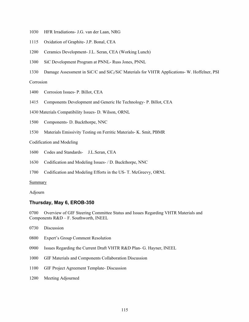
115
1030 HFR Irradiations- J.G. van der Laan, NRG
1115 Oxidation of Graphite- J.P. Bonal, CEA
1200 Ceramics Development- J.L. Seran, CEA (Working Lunch)
1300 SiC Development Program at PNNL- Russ Jones, PNNL
1330 Damage Assessment in SiC/C and SiCf/SiC Materials for VHTR Applications- W. Hoffelner, PSI
Corrosion
1400 Corrosion Issues- P. Billot, CEA
1415 Components Development and Generic He Technology- P. Billot, CEA
1430 Materials Compatibility Issues- D. Wilson, ORNL
1500 Components- D. Buckthorpe, NNC
1530 Materials Emissivity Testing on Ferritic Materials- K. Smit, PBMR
Codification and Modeling
1600 Codes and Standards- J.L.Seran, CEA
1630 Codification and Modeling Issues- / D. Buckthorpe, NNC
1700 Codification and Modeling Efforts in the US- T. McGreevy, ORNL
Summary
Adjourn
Thursday, May 6, EROB-350
0700 Overview of GIF Steering Committee Status and Issues Regarding VHTR Materials and Components R&D – F. Southworth, INEEL
0730 Discussion
0800 Expert’s Group Comment Resolution
0900 Issues Regarding the Current Draft VHTR R&D Plan- G. Hayner, INEEL
1000 GIF Materials and Components Collaboration Discussion
1100 GIF Project Agreement Template- Discussion
1200 Meeting Adjourned

116
B-3 PARTICIPANTS
Name Company
Ballinger, Ronald MIT
Billot, Philippe* CEA - Saclay
Bonal, Jean-Pierre CEA/Saclay
Braase, Lori INEEL
Buckthorpe, Derek* NNC
Burchell, Tim ORNL
Burlet, Helene CEA
Corwin, Bill* ORNL
Fineman, Cliff DOE NE-ID
Hayner, George* INEEL
Hoffelner, Wolfgang* Paul Scherrer Institute PSI
Iyer, Natraj SRTC
Jones, Russ PNNL
Kolts, John ANL-W
Lessing, Paul INEEL
Louthan, Mac SRTC
MacDonald, Phil INEEL
McGreevy, Tim ORNL
Mizia, Ron INEEL
Nanstad, Randy ORNL
Ren, Wieju ORNL
Ryu, Woo-Seog* KAERI
Seran, Jean-Louis CEA
Shaber, Eric INEEL
Smit, Kobus* PBMR
Southworth, Finis INEEL
Tian, Hongbo INEEL
Totemeier, Terry INEEL
Van der Laan, Jaap* NRG
Wilson, Dane ORNL
Wright, Richard INEEL *VHTR PMB Member

117
B-4 MEETING SUMMARY May 4, 2004
Welcome – George Hayner
George Hayner, NGNP Materials R&D Program Manager, welcomed the participants to Idaho Falls, Idaho and to the first meeting of the VHTR Materials and Components ‘Provisional’ PMB.
Welcome – Bill Corwin
Bill Corwin, Generation IV NTD for Materials discussed the NGNP Materials Plan, which was issued in November 2003. The Idaho National Engineering and Environmental Lab (INEEL) developed the requirements section and Oak Ridge National Lab (ORNL) developed the research plan. Both sites are working together to meet the needs of the DOE.
Opening Remarks – Phil MacDonald
Phil MacDonald distributed the revised version of the Materials and Components Section, Appendix 3, in the VHTR Research and Development (R&D) Plan.
Materials and Components PMB Meeting Objectives -- Philippe Billot
As the Materials and Components PMB co-lead, Philippe Billot thanked the participants for attending.
The Materials and Components PMB is the first to meet of all of the PMBs organized by the VHTR Steering Committee.
Meeting the 1000 °C is a challenge for materials development, but it is important in our search for an optimized VHTR.
We have the technical content from the participating countries, but it needs to be synthesized into a detailed Materials and Components Project Plan.
VHTR R&D Plan History – Wolfgang Hoffelner
Wolfgang Hoffelner, PMB co-lead, reviewed the history of the VHTR R&D Plan development.
Explanation of INEEL NGNP Program Status -– Phil MacDonald
Phil MacDonald discussed the changes in the INEEL NGNP program. He is now the NGNP R&D manager. He passed out the VHTR Materials R&D Plan, which has all the recent changes incorporated.
DOE has not released the acquisition strategy for the NGNP. It is still in Congressional discussions. Bill Magwood is on the ICONE panel. The NGNP will be an integrated project between industry, international partners, and DOE. This concept will bring major industrial firms into the design and construction of the plant.
A research program supporting the effort will be integrated with the GIF program. The VHTR Steering Committee and the associated PMBs will support the R&D for the NGNP. The PMBs will have fairly wide powers. The project system agreement will be discussed at the next Policy Group meeting in Sun Valley, Idaho.

118
The INEEL “reactor integrator” will have a very active role in participating in the PMBs and holding aggressive information exchange meetings. The research is intended to support the VHTR and the NGNP, regardless of the design. Even though this has not yet been approved by Office of Management and Budgets (OMB) or the White House, it should be approved by May.
The NGNP ITRG was formed at the request of DOE. A group of independent technical experts were assembled to review the current proposed designs and document their opinion regarding the design feasibility with respect to meeting the 2015-2017 operational deadline. The technical experts represented industry, nuclear utility management, and government R&D. Various subject matter experts (SMEs) were asked to present their designs and answer questions posed by the ITRG. Professor Ballinger was one of the representatives.
The current Materials and Components PMB co-leads are Philippe Billot and Wolfgang Hoffelner. The PMB needs to determine permanent leads and resolve organizational issues once the Policy Group confirms the existence of the PMBs.
Discussion
Refer to the “Creep Rupture Strength” presentation slide: The data is not from nuclear industry and is about 20 years old. There is also older data up to 1100 °C for Ni-base ODS.
Many experts in Europe believe that reaching outlet temperatures of 1000 °C is not possible for reactor operation by 2017. There must be a differentiation between current technology to meet the 2017 goal and new technology above 950 °C.
Does it make sense to talk of temperatures above 1000 °C, or do we have a near-term program for R&D up to 950 °C and then look at future R&D options for materials above 950 °C?
Discrimination between near-term and long-term materials should be an outcome of this meeting.
1000 °C is not achievable in the timescale for NGNP. However, 900 °C is appropriate followed by a design that does not preclude higher temperature modifications after construction.
The NGNP program needs a plan that addresses modification past the 2017 construction date.
We should not allow high temperature creep in class-one boundary materials.
There are relationships between the direct vs. indirect cycles and the issues between 900 °C and 1000 °C. If you need high outlet temperatures, then an indirect cycle is not possible. At 900 °C it is possible to have both cycles.
The indirect cycle is more favorable for maintenance (bearings, circulation, etc.).
The reactor is not the temperature-limiting factor. The hot duct turbine material is the limiting factor. It is okay at 900 °C, but there is a major step change in technology at 950 °C. It is hard to cool blades with helium. If you cannot cool the blades, then your options are limited. It may be necessary to go to carbon/carbon (Cf/C) blades and disks, which will be a 20-year development path.
The RPV is an issue with regards to codes and standards. The ITRG focused on a specific time frame (2017-2020) for the NGNP, but that meant the materials had to be qualified by 2009, which is more restrictive. The issues with 2¼ or 9 chrome molly become difficult with the large size of the RPV. There

119
is very little data on fabrication and qualification of these large vessels. It may be necessary to use SA-508 steel and cooling technology. Creep should not be allowed. Design a vessel where creep is not a significant issue.
Compatibility of materials for a 60-year life is a major issue for R&D.
Effort will be needed to address impure helium and Cf/C composites in a direct cycle.
Need to research the issues with radiolysis and molten salt.
The ITRG was asked to evaluate 3 concepts: PBMR, Prismatic Block, and Molten Salt. There was no showstopper with the Prismatic or Pebble Bed.
The prismatic block design had some uncertainty in the upper temperature range.
The Pebble Bed design is more mature and has less uncertainty in the upper temperature range.
The Molten Salt concept is not as developed as the other two reactor concepts.
The ITRG asked each vendor if they could meet the completion milestone given the 1000 °C requirement and if the answer was no, then at what maximum temperature could be achieved given time constraints? In every case, the answer was no and the maximum temperature achievable was 850-900 °C.
This is one of the differences between the VHTR and NGNP goals.
Issues with the turbine materials were discussed at the ITRG meetings.
The ITRG had Mitsubishi Heavy Industries (MHI) and Toshiba discuss the turbine materials issues. There is no proven high temperature turbine design.
The 60-year design life is another major R&D issue. With continuous replacement of components and parts, the temperature is not a major issue.
Helium cooling, according to MHI is too good, creating thermal stresses that are too high. With non-cooled blades, there is a potential inability to change out components.
Q: What information is available on nickel (Ni)-based material studies at 1200 °C?
A: Inconel 617 is a typical furnace material. It takes about seven years to take material from ground zero to code case approval. The allowable stresses won’t be qualified in a nuclear reactor application. They may meet the temperature requirement, but they will not meet the stress requirements.
The allowable stresses are so low on the IHX that an operating curve is necessary where you have to have zero differential pressure to keep the stresses low.
Current Issues and Status of the NGNP Materials R&D Program Plan -- George Hayner
The focus should be on a materials research plan.

120
There are references made to prismatic block, helium-cooled reactor; however, the design has not been determined.
It may be that research activities will need to be approved by applicable industrial firms sometime in the future.
ORNL has been successful with industry collaboration in the past and this will very likely be the case for the NGNP. This approach keeps the research “applied.”
Q: Can we develop a program plan without an industry partner?
A: We hope to have a design and design team for the NGNP in about two years. In the mean time, we have to proceed forward with broad research to support the NGNP and a number of possibilities of the VHTR for other GIF nations.
Q: Can you describe the design of the EOI that is being prepared?
A: No, we cannot discuss this at this time.
Q: Why is the hydrogen not included in the materials program?
A: There is a NTD for Energy Conversion, which is Paul Pickard. He is also running the program to develop the hydrogen generation project, which is a coupled program. Bill Corwin is working with Paul Pickard to develop the Program Plan for hydrogen generation. It will cover NGNP and the other GIF reactor systems.
Q: In the hydrogen project, there is not much substance for material issues. This should be addressed with the VHTR Steering Committee.
A: Many issues overlap with the reactor system and the hydrogen production system.
Q: The hydrogen production project is looking at composite IHX research.
A: This is not a part of the Materials and Components PMB scope.
Presentation Correction: The RPV for the PBMR is 300 °C and the PCU (PCU) pressure boundary is 100 -110 °C. This is a radiation issue.
Q: Note: 30-dpa is applicable for control rods and the rest of the internals are appreciably lower.
A: This is a maximum. We have the calculations for the other components.
The NGNP – Insights Gained from the INEEL Point Design Studies – Phil MacDonald
Whether 1250 °C is a reasonable operating temperature remains to be determined as well as whether 1600 °C is a maximum temperature for the fuel. (This is based on German results with low packing fraction and low burnup). We need to achieve high burnup with a high packing fraction for the NGNP/VHTR.

121
To get to the 1000 °C outlet temperature, the bypass flow was cut and the flow distribution was optimized in the blocks.
Block reactors are much more susceptible to water ingress than the PBRs.
Reactivity goes down with higher packing fractions. There is an issue with fuel failures. Current assumption is about 40% fuel failures. On-going calculations are being done to determine reactivity.
There are issues with turbulence and buoyancy in the flow channels. This issue may also apply to the pebble bed concept.
Pebble Bed Attributes
Fuel temperatures in a PBR are lower than block reactors with the same power output. Water ingress is not as much of a problem.
Enrichment differences exist between pebble bed and prismatic block reactors.
Output of reactor designs is an economic decision. The 600 MW is a study case.
Q: Are there better numbers defined for upper RPV temperatures for conduction cool down events? If you have a cooled RPV, how do you meet the passively safe requirement? What are the safety differences between an insulated cooled vessel compared to high temperature uncooled design?
A: Inlet temperatures for GA was 490 °C, Framatome was 400 °C, PBMR uses cooling to reduce temperatures to 300 °C. The GA average temperature is about 440 °C, but it is in the creep range. Temperatures above 400 °C allow no consideration of creep. 490 °C is the low-end of the creep range. The Framatome concept is an indirect design.
The PBMR still relies on high emissivity. It is insulated on the inside with gas. If the independent cooling system is lost, then they could exceed maximum design temperatures. The cooling system is for protection of the investment, not for safety of the public.
Q: When representatives met with the NRC Office of Research, they commented about operating a RPV in the creep range; they did not see it as an issue and seem to be open to new research methods.
A: PBMR prefers to be out of the creep range. It is already hard to inspect this type of reactor. The beltline area operates at 300 °C average temperature. The RPV sees a different flow from the PCU. During a depressurized Loss of Coolant Accident (LOCA) analysis, the temperature in the RPV beltline area can raise to ~500 C. PBMR is not actively cooled.
The core barrel would have to be monitored if operating in the creep range.
NRC is worried about hot spots in the PBRs. Significant temperature differences in the AVR were detected and the cause was not determined. AVR outlet temperatures were supposed to be ~950 °C, but they were operating at 1050 °C at times. How hot are the hot channels? How do you calculate the temperature?
Q: Was the pebble bed optimization carried further with fabrication and integrity?

122
A: We did not move the dimension enough to create a fabrication issue. Fuel duty is milder and temperatures are lower. Fuel fabrication should not be as difficult. Fuel handling is difficult with the pneumatic handling in the pipes. We left the packing fraction the same and the pipe dimension at 6 mm outside diameter.
Q: Are the reactors going to be designed with on-line monitoring?
A: It is being considered, but there are many issues, such as temperature and radiation. It is essential for operations in the creep regime.
Reactor Pressure Vessel Steels and Irradiation Issues – Randy Nanstad
Note: The symbols in the presentation should be “approximate” symbols.
There are RPV steel and irradiation issues to resolve.
RPV operating conditions range from 650 °C up to 770 °C for off-normal conditions.
Heavy Steel Structural Inspection Program.
Irradiation, Annealing, Re-irradiation Capsule tests.
University of Michigan Ford Nuclear Reactor program was closed. It was one of the test facilities to test capsules.
A capsule is inserted into another capsule and irradiated. It is taken to a hot cell to remove the capsule and do the analysis.
Action: Need to add the ORNL Irradiation Tests to the R&D plan, the schedules, and the matrix.
Q: Do you intend to incorporate weldment samples?
A: Yes.
Q: What is the flux for the tests?
A: Flux of 2 X 10 12 neutrons per cm2 to get to .0075 dpa in a few months. But for higher fluences for the LWR case (dpa of .04) it will take about 2 years. Testing will be done for both to build the testing facility.
Q: How large of a materials test program are you anticipating?
A: We are focused primarily on the design choice for the NGNP program for the first reactor. But we would be short sighted if we don’t look at other materials as a contingency or for the nth reactor for the NGNP. We have not identified these details yet.
Normally, RPV and internals are two different development issues. There is a lot of discussion of materials and testing in unirradiated conditions separated from the radiation tests. We anticipate the unirradiated test program to be bigger due to larger effort on potential candidate materials. Long-term irradiations will probably include only 2 materials. It involves a lot of initial testing to identify candidate materials. Literature review and initial assessment of capability to be ready by 2010 will eliminate many of these materials.

123
Q: Have you started R&D on 9-chrome molly?
A: For Gen IV purposes, we are waiting. But there has been significant work done at ORNL and in the fusion program. We have not begun any experimental work for the NGNP/VHTR due to lack of funding.
Metallurgical and Mechanical Studies of 9 Cr Steel for Vessel Applications -- J. L. Seran, CEA
Q: The hot cracking work for commercial practices is being done by Framatome and will be completed this year, which will end this industrial activity. The advanced studies are of concern. Is the laser welding for final end field application? Is this research part of the EU program?
A: No. It is a collaborative effort between CEA and Framatome.
Q: Has the class of steel in the upper class structure been evaluated in the mixed mode?
A: We have found they are about half the strength in mixed mode. The codes only talk about mode 1 in the upper shelf. With multi-axial testing, your mechanical properties go down.
Q: A lot of testing has been done to get the materials in the code? Do you see this as a duplication of testing? From a design point of view, do you adhere to code rules?
A: CEA is working on code acceptance.
Q: What about tests on other grades of 9 chrome?
A: There is a fusion program for doing some testing. We would like to test unirradiated material such as titanium and then to optimize the composition of the grade 91. We would also like to test to grade 92 (this is another program).
European Union Irradiation Test Program – Derek Buckthorpe
Fifth Framework data:
Irradiation testing is done. The Post Irradiation Examination (PIE) will be done offsite at Petten starting in the next couple of months.
These tests include taking different parts from the heat-affected zones to analyze.
One set of base plates will be tested, but some have been held out for future testing.
Data show 8 dpa with a temperature of 375 C. Looking at the lowest potential temperature in the cycles.
At the higher temperature, annealing removes the radiation and the effects are less.
Q: Did you consider doing tests at higher temperatures?
A: We wanted to answer the lower temperature questions first, and then look at the upper temperatures. We are looking at one temperature, not a range. The analysis focused on the comparative effect, not the population of a database.
124
Sixth Framework
Work is planned at the same irradiation temperatures.
On the vessel structures, the tests are moving away from the smaller components to the larger structures.
Q: How thick are the cylinders?
A: They are scaled down, but they will be representative. There will be some microstructure tests to understand behavior.
One of the crosscutting material studies will be the establishment of a US database of the high temperature materials. The Nuclear Systems Handbook will be a start.
Q: How do we merge the Euratom databases and the US database?
A: It would be very valuable, but this is not a NGNP materials activity.
Action: We need to look how to do the collaboration to merge these databases. ORNL and Euratom.
United Kingdom Program (second presentation)
The United Kingdom Program is complimentary to the Euratom program.
Materials R&D Program at KAERI (Presentation) – W. Ryu, KAERI
KAERI is working with industry?
Deco Heavy Industry (DHI) is a fabrication company working on composites.
RIST is doing some graphite work.
Korea Institute for Energy Resources (KIER) is looking at hydrogen production R&D.
Q: What are the irradiation doses for these components at the1100 °C temperatures?
A: 14 X 1014 but the dpa(s) are not known.
Q: In order to construct the demonstration Nuclear Hydrogen Plant (NHP), are you also constructing a reactor?
A: Yes, this is a VHTR with hydrogen production. Currently, we are considering just the production of hydrogen, not electricity.
Q: What is your development timeline?
A: Same as the US. The design group has developed the schedules.
Q: What are the materials for the piping and internal IHX components?
A: We want to pick a group of materials in the First Phase to then identify the candidate materials. We are looking at Hastelloys like the US. We will be doing the screenings.

125
Q: What is strategy for research and how do you intend to use the Gen IV program?
A: Their hydrogen program is a separate program, but we want to look at ways to connect to the Gen IV Program.
Q: What is the difference between the SMART program (mid-term) project and the Hydrogen Demonstration Program (long-term)?
A: Development time.
Q: Will Korea be able to fund both?
A: Yes.
Q: Are you looking at other hydrogen production technologies besides Sulfur/Iodine (SI)?
A: We are looking at the SI process. Others have looked at other technologies.
CEA R&D Program on High Temperature Metallic Materials – H. Burlet, CEA
We are looking at these experiments for the VHTR direct cycle design.
Haynes 230 is a new material that we are working on qualifying for the VHTR program.
Studies are being done on thin plate IHXs.
We don’t know the composition of the gas of the secondary loop. If it is a nitrogen and helium mixture, it will influence the design. Clear direction of the gas composition would be helpful to move forward on the design.
A program is starting to look at the plates and how to join them together for Fe-ODS material (braising ceramics and metals). We are not doing this for the VHTR, but it could be included.
We are doing feasibility tests on joining technology. We need to know the geometry of what is being joined. We try to think of different processes that may apply to a certain design. Knowledge of how the gas will enter the IHX is needed. Have to consider the whole system design for this development.
The turbine for the VHTR is different than turbines for industry.
Q: What are the fracture toughness properties relative to the grain size of the powder?
A: All the analysis has not been done yet. It is a new material we are currently testing.
Euratom Activities for Materials and Components -- Derek Buckthorpe
Firth Framework Program (5FP)
Differences between the 5th and 6th framework programs apply to metallic development, not the vessel.
One of the program focuses was to retain and reestablish expertise, by bringing in younger engineers.
Sixth Framework Program (6FP)
126
Testing on high temperatures materials. Looked at large disk-single application technology.
Q: How were the tests done on the disc and blades?
A: With a gas system and rig. Tests have been done in air on the disk material. The short-term tests will be completed this year and the medium-term tests will be done next year.
Q: What kind of temperatures are you expecting for the internals and IHX?
A: We were aiming for 1000 °C. But we are looking for what is feasible, manufacturable, weldable, and can be used with existing codes.
United Kingdom Activities for Materials and Components
Q: What are your VHTR gas chemistry studies?
A: Some testing is being done on helium loops with CEA. We will focus on modeling methods for the material in the environment with regards to corrosion.
Q: Did you assume equilibrium in the gas phase?
A: We took representative samples, used the existing data.
VHTR gas chemistry and activation issues. Used for protection from active elements and corrosion. Look at it from a protection point of view, but largely at corrosion.
There is a lot of work in the turbine industry on spallation and coatings of blades.
Damage Assessment in ODS and Intermetallics for VHTR – Wolfgang Hoffelner
Q: How does the irradiation affect the diffusion-controlled areas?
A: When you extrapolate, extreme temperatures or stresses are used. This is a Paul Sherrer Institute (PSI) government-funded institution, with 1000 employees working on a fusion program and beam line research.
We will not have a good idea of mechanical behavior in the next couple of years. But we are starting on the research.
We are looking for damage assessment on material samples.
This is an area with three lobes: the NGNP, fundamental work of PSI, and crosscutting activity of microstructural analysis and modeling, which supports the Gen IV program.
Q: Is there an interest to incorporate this research into the NGNP or VHTR program?
A: It would be appropriate for the program to incorporate the materials testing programs.
We don’t have this research built into the NGNP program. There is some research included in the international work in support of the VHTR. This should be discussed in the NGNP and the VHTR program. It seems appropriate to include longer-term research in the plans.

127
Action: Consider adding this research to the NGNP program.
Internals and Structural Materials – Wieju Ren, ORNL (Presentation
ORNL has the ability to test stress and creep up to 1600 °C and the ability to test very large loads.
It is going to be at least two years until we have a design for the NGNP. There are certain R&D areas that we know we need to move forward on and we need to start our research projects now.
George Hayner and Bill Corwin have a prioritized list of projects, but many fell off due to lack of funding. George and Bill need to take another look at their prioritized list to see what can be started.
Q: What are your plans for research in the next two years? What materials and tests are you going after?
A: 617 XR and 800 H are the leading materials. We submitted a testing plan earlier this year. Step 1 will be to down select. We need to reevaluate the plan in the new light of the DOE direction.
Action: Bill Corwin will relook at the testing plan for research over the next two years and send the updates to Phil MacDonald.
Q: Turbine designs?
A: Oberhausen built a turbine at 50 MW and it was a helium turbine. It was meant to be representative of larger turbines. The VHTR will need a 200 MW turbine.
Q: Pebble Bed turbine?
A: The turbine issue is with the bearing size. There are 3 vertical shafts, which separate the high-pressure from the low-pressure from the power turbine. Mitsubishi designed the turbine. They have a 10-20 test bench and a materials side, which needs to be involved to evaluate materials and creep.
Q: When is the turbine due for delivery?
A: Approximately 2009, designed and delivered. This is based on the design completed in 2007. The concept design phase is finished. Basic design will be completed in 2-years, and should start this year. After this, the long-lead components can be ordered.
Q: How are materials issues for the turbine being handled?
A: We are using approved materials designed for 200 °C. During basic design there will be a two-year test phase. The working fluid will be helium. We have been through three design interactions during this concept phase. The turbine will be uncooled and uses cobalt to satisfy cooling and activation concerns.
The overall efficiency is 42-43 percent based on the electricity put on the grid. Efficiency is defined as thermal energy generated. Helium will have a lower efficiency than an air turbine.
We could be looking at a helium or air turbine depending upon whether it is an open or closed cycle.

128
Study of Creep Fatigue Environment Interactions in Inconel 617 – Terry Totemeier, INEEL
We plan to look at how the environment interacts with mechanical loading. We are looking at an environment that is active.
Will also be looking at non-failed test elements.
We are keeping the test parameters limited.
Q: Is there any oxygen embrittlement data available on this material?
A: Not that we have seen.
Laser Ultrasonics: Look at wave speed and attenuation. This is a non-linear ultrasonic approach. Coupling of the surface is important. This is a piggyback effort with an Office of Science project.
Idea: Look into other similar areas of research. The air force has been doing similar tests.
Effect of Orientation on Creep Strength of MA 754 – Terry Totemeier, INEEL
The assumption is a Brayton Cycle with 20 MPa for the VHTR.
The transverse direction is weaker than the longitudinal strength at 1000 °C.
At each temperature, the ductility decreases with the longer life.
At 1000 °C creep is seen at the higher temperatures.
Q: Why are the properties for ductility for the transverse direction not as good?
A: The strong texture is the main reason. There is preferential orientation of the solid and there are many stringers with inclusions. Japan has some ferritic properties.
Q: How do your worst properties stand up to Cf/C?
A: Cf/C should be much stronger.
Q: Is there a difference in the specimen size concerning the transverse?
A: 55 microns in grain size in the transverse.
Weldability research is a different program under Kevan Weaver, co-chair of the GFR Steering committee. We have a subcontract through Auburn University. We have made some bonded joints.
There is another program in fossil energy at ORNL. The problem is tool material. We have come up with refractory metal tools. The target is to do ODS materials.
Q: Can welding be done on a counter-current IHX? What about leak tightness?
A: Yes, theoretically we should be able to do it. The trick is to control the grain structure. The process is to save oxide dispersion.

129
Idea: Oxide Dispersion – Good area for collaboration.
Q: What would the code require?
A: There was a code case for 617 that came close to approval, but never made it.
Grain boundaries are increasingly weak at higher temperatures. Also the tensile ductility goes down. This could be another avenue of alloy development to look at what can be done to prevent the weakening of the grain boundaries.

130
B-5 MEETING DISCUSSION May 5, 2004
Graphites and Composites Development for VHTR Applications – Tim Burchell, ORNL
The Materials R&D Project needs to include the way the graphite is made.
It takes 9 months to manufacture graphite.
Key steps are the manufacture of the coke; the way you form the material; and the graphitization (temperature).
There should be a design database of physical and mechanical properties of graphite. (International Collaboration opportunity.)
Q: What makes a good raw graphite product?
A: Coke that combines good crystallinity and has random orientation of crystals with good CTE. Low CTE coke is not desirable. Need high isotropic coke with high CTE. Generally you don’t mine the coke. It is manufactured from heavy residues (pitch) from oil. We know enough to determine the appropriate coke, but it is more art than science.
Metallurgy coke is spongy. Graphitization would not provide the high crystallinity needed.
When you take the pitch through the coking process, the mesophase forms large crystallites, which can be stretched. Coke gives you non-isotropic properties, which is good for graphite for electrodes, but bad for nuclear graphite. It changes shape rapidly under radiation.
Choice of pitch and process produces good nuclear graphite. Preprocessing of the pitch. Want to have a pure feedstock.
Forming method also imparts anisotropy into the graphite.
The higher the graphite temperature, the more crystalline the product will be.
Purification is important. (Issues with boron content and boron equivalents).
There are 3 graphites available now.
“Aged” means exposed to environment.
Emissivity of graphite: 0.05 and 0.09 makes a big difference in the designer’s calculations.
Q: What in the graphite would change the emissivity?
A: The fineness in the structure of the graphite can change emissivity. The crystallinity factor is a good indicator of how the graphite will perform in the reactor.

131
Historical data on graphites does help, but you can not go to the NRC with this data without doing further tests on the new graphites. Use the existing data to see what is going on. The designer can use this to increase confidence, but further tests and data are still needed.
Q: We have the FSV reflector blocks. Would we learn anything form inspection of this material?
A: Possibly, If we see massive cracks or evidence of destruction. We would have to know the dose and temperature history of each of the blocks.
Q: Would microstructural exams be valuable?
A: Yes, if you know the temperature and dose history, then knowing how the graphite has changed is valuable. The data is only as good as your core history.
In metallic reactor structures, issues with in-service performance can be replicated, but not the dose rate.
The temperature of irradiation makes a big difference in determining the impacts of the dose rate. Above 400-500 °C, the dose rate does not matter.
Action: ORNL – think about whether we should pursue the FSV evaluation. Phil MacDonald thinks he can get some good data from GA on the FSV operation (temperature and flux). Phil MacDonald will talk to FSV and then discuss further tests with ORNL.
There are a few H451 blocks that have not been irradiated. ORNL has some billets that have not been irradiated.
Q: What facilities are studying graphite?
A: On a TGA (Thermographic Analysis). On a larger scale, there may be a rig at the INEEL to do oxidation reaction studies.
Collaboration Opportunity: Irradiation facilities that should be considered to determine the effects of neutron irradiation on graphite materials and composites are ORNL, HFR (Petten), and ATR.
Coke supplies are a constantly evolving situation. The only way to ensure you have enough coke is to buy enough upfront for 25 years.
Composites
The Cf/C material is more developed than SiCf/SiC or Cf/SiC composites. R&D for the short-term will likely focus on the Cf/C material with longer term R&D for the advanced composites.
Collaboration Opportunity: Provide design database of physical and mechanical properties of composite materials.
Codes and Standards Development
DO2-F is the committee for the Petroleum Industry.
A materials specification is under development to meet the requirements of the code.

132
ASTM would welcome international participation at their meetings, e.g. Salt Lake City.
Q: What range are the temperatures for CTE?
A: They range from room temperature to 500 °C. The way you sample and test is also specified.
ASME Code Development
The code for core support structure was never adopted. Have been working to reintroduce the code for adoption. Have formal standing as an ASME Section III Project Team.
Boiler Code Week is next week.
Charter:
Why were blankets excluded?
We did not consider this as a breeder reactor.
Our focus is on fission reactors.
Q: Does it make sense to put fracture mechanics methodology for graphites and composites in the same code development?
A: We will separate them and may end up with two standards or one standard with two sections. There will be separate rules.
Q: Is there an aerospace code for composites?
A: Yes/No: A composite that was designed for the tail of an aircraft would not be the same as for a control rod. Some of the mil-specifications may be applicable. Material is architectural dependent.
Some ASME Section VIII activity for industry may also be used for some applications.
One of our tasks will be to search all the codes to see what is applicable and to identify the gaps that need code development.
Q: Irradiation creep, do you have some means or development on this?
A: Yes. We would have to build a new rig to do experiments. One was built for GT-MHR and the prototype was built and tested. We could see if it is still applicable. This could be done in Osiris reactor.
Q: Do you follow creep during irradiation?
A: Probably, with post irradiation tests. The capsule has control of temperature and stress samples and unstressed samples. Look at differences to get the creep behavior.
We need to figure out what dose we want to use for testing. Without a design, it is hard to know the dose to test to.

133
Is HFIR sufficient to get a representative dose? ATR has the right flux and down tubes, but it is costly. If we could get our radiation needs lined up, we could determine which reactor to use. Would have to determine HFIR isotope commitment.
Q: Could the funding for the gas fast loop be redirected?
A: The Gen IV program has not come forward with a strong need for the ATR facility.
Action: Tim Burchell: Forecast out about 5 years to determine the need for ATR and HFIR. Please consider also a PBMR vs. non-PBMR. This will affect the dose needs and irradiation plans.
For the larger structures, you don’t need to pay the development costs for the SiCf/SiC. Can you have lifetime performance from this material? This is up to the vendor to prove, but we need to provide the technical input.
Graphites and CC Composites – Derek Buckthorpe, NNC
EURATOM – Fifth Framework (Practical timeframe 2000-2004)
From the beginning, we brought in the manufacturers to support the analysis activities.
Limit on Alloy 800H.
If the Japanese use the ASME code and they were at the limit, they would have to change the operations procedures. Looking for physical and better thermal properties. Physical properties change with temperature. The thermal properties were still better than the steel. Radiation has an effect on the properties, but it is still better than the steel.
Collaboration Opportunity: Gather information for a graphite database by doing the testing necessary to determine properties for new graphites. Data is currently commercially restricted. There is no reliable model developed from the past to predict performance of graphite, because of the number of tests required.
Q: What do we know about annealing mechanisms?
A: We are aware of it in silicon carbides.
Q: Is there some annealing of damage above temperatures of 1000 °C?
A: There is an equilibrium set up between the damage and the annealing behavior.
Q: What is the mechanism?
A: It depends on the irradiation temperature. You build up a cluster of extended radiation defects and these have to be broken, which is why higher temperatures are needed. We are looking at an experiment of a heat up accident. Properties could change when looking at what happens with decay heat.
Q: Does graphite burn when oxidized?

134
A: The reaction is exothermic, but you can’t generate enough heat to sustain the fire. The THERA facility in Juelich says you can burn the graphite.
Q: What happened in Chernobyl with the burning graphite?
A: There was a lot of heat added to the graphite from other mechanisms.
ATR-2E is German graphite and is no longer manufactured, but they have a lot of data. We will need to recreate this curve for the new graphites.
Q: Is a 100-degree change for graphites a big or insignificant change?
A: It is a relatively big change. The turnaround temperature or where the graphite has the longest life is in the 600 to 700 °C range. At 1000 °C, there is axial and radial distribution. It is constantly changing.
Q: Will it be possible to hold the bypass at 10%?
A: As the blocks shrink initially, the gaps between the blocks will change dimension. They will open initially. The irradiation creep adds some forgiveness. It is it more forgiving at the higher temperatures. Creep is more of a load function rather than temperature.
Sixth Framework (Practical timeframe 2005-2009)
Opportunity: Graphite irradiation tests and Cf/C material tests above 950 C.
Q: Is it really possible to model microstructure irradiation behavior of graphite?
A: We have to figure out how to model it to prevent the reinvention of the wheel every four years.
Q: NGNP Qualification Document: GA dose information for core support structure, control rods, etc., is a single data point. What do you expect the dose ranges for the removable and non-removable parts would be?
Action: Prepare a two dimensional matrix that compares temperature with dose for the range of components (and composites) expected. We have this information for GA, but we need it for PBMR and CEA.
United Kingdom
Q: Is there a consensus for irradiation of graphite? Criteria?
A: It depends upon the reactor design for the graphite performance. The reactor concept will determine the criteria for the graphite.
NRG Presentation on Materials Testing – Jaap Van der Laan, NNG
Q: Can you do on-line temperature control in all positions? (Page 13)
A: We can do on-line temperature control, but not in all positions. Heating is from decay of gammas. There is a temperature gradient across the capsule. Each can have two individual gaps.
135
Q: Have you received input from the Space Nuclear Application?
A: No.
Oxidation of Graphite – Jean Bonal, CEA
Structure of the coke is very important.
The molded graphite has higher mechanical properties, but that does not mean they will have less cracking.
With high strength fine grain graphite, with low crystalline size, and experiments at 35 dpa, the graphite will show lower swelling.
For the PBMR, the life determining block could reach the limit at the temperature of 900 °C. The surface temperature is not the limiting condition.
At low temperatures, <600 °C, you see a lot of oxygen (oxidation) throughout the graphite. Porosity is the mechanism of transfer into the graphite. Carbon reacts with the graphite. The oxidation rate is low.
Q: What is the primary effect of impurities?
A: Impurities act as catalysts for the oxidation.
Q: Are the impurities consumed in the oxidation process?
A: Possibly.
Grade A = isotropic graphite.
Grade B = near isotropic graphite, extruded.
At high temperatures >900 °C, the oxidation rate is high, but it only occurs on the surface and does not affect the mechanical properties. Reacts quickly with carbon on the surface.
Waste management of graphite includes two options: storage or reuse of the irradiated graphite. (Storage space of irradiated graphite is an issue.)
Q: How much graphite will be required for initial startup and for the life of a VHTR reactor?
A: About 800-1000 tons.
PBMR reflectors = 1000 tons.
French = 6 reactors for power and 3 reactors for military. Produced 22,500 tons of graphite.
Q: What is the ½ life of chlorine 36?
A: 300,000 years.
Q: Is the chlorine present as a gas in the graphite?

136
A: We are not sure of the chemical form. May be as a chloride or gas after irradiation.
Q: Have there been any experiments on post-heat treatment of graphite to see if they can remove the chlorine?
A: Last reactor was shut down in 1994. The fuel was removed; however, the graphite is still in the reactor. We may use the irradiated graphite from the first generation to experiment on heat removal.
Cf/C Composites
Idea: We should be considering Silicon Carbide as strongly as we are Cf/C, depending upon the economics.
Cf/C composites swell in perpendicular direction (radius) and shrink in horizontal direction (length). Produces a “football” shape. This is based on non-isotropic material.
Irradiation time is one hour.
Collaboration Opportunity: It is important to identify the areas for collaboration in the graphics and composites area.
Ceramics Development (Working Lunch) – J. L. Seran, CEA
This presentation covers other programs, such as the GFR.
Selection criteria for ceramic core materials are based on physical and mechanical properties, which should be as high as possible and neutronic properties, which should be as low as possible. (Rehibitory neutronic absorption.)
Q: Are there specimens and properties for each material?
A: For the majority, yes; however, the exception is Mo-TZM. The others are either ceramics or metallics.
Q: What is the application?
A: To determine the properties on the Mo-base alloy for the structural materials. One is the inert fuel matrix material that surrounds the materials. Second is the material for the potential support members in or near the core.
SiCf/SiC Composites for Advanced Nuclear Applications – Russ Jones, PNNL
Note: Transmutations shown on the SiC presentation slide apply to the fusion program.
SiC swelling past 400 (K). Some data suggests void swelling causes the graph to go back up again.
Hi-Nicalon and Type S Nicalon Fibers under radial stress, rapidly reaches stress that it can not tolerate.
Bend strength shows about a 50% percent loss.

137
We are looking at the dynamics of a single crack (still get multiple cracks, but we are focusing on the single). This is how the material creeps.
Time dependent composite behavior; fibers are controlling the creep rate of this material.
Pulling on the fibers causes debonding.
Effects of oxygen on crack growth.
The crack goes through the matrix and damages the interface. It reacts with the oxygen. It has a longer fiber length.
Looking for joining methods in the field that can be done without pressure.
Collaboration Opportunity: Evaluate the University of Bordeaux’s multi-layer interface with a strong first layer/fiber bond, which forces multiple cracks along the multiple layers. Force the cracks to create a stronger material. Unsure if this R&D is under progress. There may be an International Nuclear Energy Research Initiative proposal. Need to look into their studies on multi-layer interfaces.
Controlling oxygen and helium to low levels to extend life of materials. Multi-layer applications may be good because the layers are thinner. Enough oxygen could cover the layers with a thin carbon layer.
Q: Is there any macroscopic stress threshold low enough where creep would be unlikely in a radiation environment? What are the stress levels in the control rods?
A: Values were fairly low for fusion program. Need to do the calculations for fission. Figures are normalized.
Q: What are the stresses in the components in this environment?
A: The worst problem may be in seismic, but that is a short-term stress issue.
Strength of material with cracks does not reduce the fracture strength. Cracked but not damaged as long as you are not in the stress rupture regime. Assumes no oxygen.
Action: Bill Corwin should look into this issue further. Is there a lower threshold creep strength of SiCf/SiC composites and if so we should compare with the long term loading stresses for the control rods. Strength Issue.
Action: Russ Jones will send his paper on Fracture Toughness of SiCf/SiC Composites to Lori Braase. (Action complete.)
Issue: We need to get below 1 ppm of PO2 (oxygen) (Life Prediction Model Application). We need to do more analysis and to go lower to extend the life. This is based on a model that is still being validated. It will be low because you don’t want a lot of oxygen.
Q: What is the oxygen partial pressure for gas reactors?
A: Some gas industry experts say they could get below 1.

138
The multi-layer interface (material) and the environment are two areas for further analysis.
Trying to predict environment ranges will be a critical piece.
Dimensional changes are much smaller than in the Cf/C material. It is based on point defect.
Q: What was the initial crack size?
A: Unsure, but it cracks immediately when it is loaded.
Q: Is SiCf/SiC good for tubing application?
A: It should be if weaved right, but we don’t have properties on tubing material. It has not been proven. A lot of fiber architecture work needs to be done.
For economics, we should focus on Cf/C for areas where it will work. But look at SiCf/SiC for other applications. The cost is in the fibers. This is more expensive than Cf/C.
Damage Assessment in SiCf/C and SiCf/SiC materials for VHTR Applications – Wolfgang Hoffelner, PSI
Corrosion Issues – Philippe Billot, CEA
Mechanical solicitation = loading.
Q: Did you cover the range of chemistries for VHTR vs. GFR?
A: No, for the moment only VHTR. Ranges are provided.
Q: Two tests facilities, one applying stress and another no stress. Are both facilities being used?
A: The first stress corrosion tests have been conducted. We will have a screening test to select good materials. We need to progress in the program. Overtime, a broad cross-section of materials will be tested. There is no stress facility; it is used as a screening test.
Q: Do you have complete control over the atmosphere they see?
A: Yes, especially on the second facility. We will have some measurement at the inlet and outlet of reactor. The medium will be controlled. Purification is built into both facilities.
Q: How do you characterize oxidation under stress? Do you do in situ measurement during stress?
A: No. In situ measurement of the oxidation is done after the stress test, but not during the test.
Components Development and Generic Helium Technology – Philippe Billot, CEA
Heat Exchanger Experimental Program. The Plate Fin IHX will be tested this year. This is a recuperator.
Q: Is it a conventional design?
A: Yes.

139
Q: Will it be tested at 950?
A: No, only at 500 °C. This is only for the recuperator.
Helium in the primary and nitrogen in the secondary will be the base test. But we can do the tests for both.
There will be impurities in the helium. Impurity control is in both primary and secondary circuit, both under the prototypic Delta P.
Q: What materials will apply to the IHX and recuperator?
A: Stainless steel at 600 °C. IHX will need heatrix and braising technology. Ni-based material and different processes will also be used.
Q: Which will be built and tested?
A: Inconel 617 then move to others after this testing.
Q: How are you handling the technology development with heatrix?
A: There have been many discussions, especially with Framatome.
We cannot discuss the processes or design. We can discuss the mechanical properties.
Q: How large will the IHX be for a 1 MW?
A: 100th module to obtain a 1/10th mockup. About 70 cm.
Q: What about velocities? Coupons and or components?
A: There is a test section to do both. This is the high velocity loop? Q=0.3 to 0.4 kg/s (What is the US velocity equivalent?)
Q: Will you be introducing graphite dust to study the tribology of the dust?
A: Yes. But it may not be the first program that we do.
The facility should be finished by end of 2006.
Q: In the Helite loop, what are you using for tubing or piping?
A: Unsure, maybe ni-based material.
Materials Compatibility issues – Dane Wilson, ORNL
Issue: Where is the boundary between materials and components and the hydrogen and who is responsible for the intermediate heat transfer loop?
External oxidation resistance: Chrome provides the resistance on the outside and nickel provides the resistance on the inside.

140
Framatome would not consider molten salt as a heat transfer medium.
In the ITRG, there was no industrial interest in the use of molten salt.
The utilities also did not show interest.
The committee said there were too many unknowns for deployment by 2017.
We should proceed with hydrogen and leave molten salt on the table.
We need an unbiased analysis of molten salt. Need to look at how the environment affects the material and look at site ability.
The composition of molten salt involves two opposing sets of criteria one nuclear and one chemical.However, this does not apply to the secondary loop.
Components - EURATOM – Derek Buckthorpe, NNC
Fifth Framework
Work packages are aimed at the direct cycle.
Largely recuperating the previous experience for future FP6 planning.
850 °C component temperatures.
Sixth Framework
Principally focused on the indirect cycle, but most components can apply to both cycles.
Higher temperatures that 850 °C.
Emissivity Measurements on Ferritic Materials – Kobus Smit
Tests are based on the PBMR design.
PBMR currently has a 40-year design life.
Pressurized Loss of Forced Cooling event.
Sample dimensions – graphite 3mm and metallics 6mm.
Be careful with accelerated test with 316 and other high alloy material in pure helium. May lose any oxide that you create.
Q: Looking at the inner surface of the RPV and how it is affected by helium in the long-term. Are you counting on absorption as the primary heat transfer system or is it convective.
A: There is a relationship between the absorption and the emissivity. If we can guarantee the 0.9 for life, we are going to do this long-term testing (3000 hours on the 308 at 400 °C). For the core barrel, we will be testing at 500 °C.

141
Codes and Standards – J. Seran, CEA
ORNL data and RCCM design curve. Assume there are conservatisms built in.
Q: Are you going to look at other grades besides T91.
A: No, only T91.
Action: Resolve the inconsistencies between the uses of the ORNL data in the CEA analysis.
Codification and Modeling – Derek Buckthorpe, NNC
FPP – Identify the codes to prepare the framework.
Q: Which specific codes are you talking about?
A: Within the Euratom partnership we have RCCM codes, ASME codes, RCMR, PNAE. There is a mix of code experiences.
Action: It would be useful for someone from Euratom to join the US code development.
Q: Are you going to look at European Standards Organization (KTH) codes? (German)
A: Yes
Codification and Modeling – Tim McGreevy, ORNL
Q: Why is 617 excluded for bolts.
A: Stress issue.
982 °C = 1800 °F for 617 – very low. Limited to 100,000 hours (which is 10 psi). A 60-year life is 500,000 hours.
Q: Regarding the isochronous curves, how much strain is generated from a certain amount of stress over time?
A: Inconel 617 is very time dependent and we don’t have experience designing with it.
We need to look at reducing the pressure.
Issue: Must address the ratcheting or accumulation of strain in simplified methods. However, the simplified method (Bree Method) assumes a 1-D stress analysis extrapolated to all the components. There are concerns with this assumption.
They do have some restrictions. There are some margins, but are they good enough or are they too conservative.
This information is not for the VHTR; what happens when we start looking at the VHTR parameters?
1% maximum strain though the wall thickness. (Bree Diagram).

142
Issue: We need to look at how we do accelerated testing for creep fatigue. Charts show a summation of creep damage and a summation of fatigue damage. At low percentages, tests show low in the non-conservative range.
Inconel 617 (Some data was extrapolated from knowledge of 604).
There are some specifications developed by the airline industry that resolve some of these issues.
Lower ductility when you test in helium than in air.
Issue: We need to be careful of helium testing that may have a higher percentage of oxygen. Be cautious about the data and how old it is. (Ron Ballinger has examples of tests done in helium that had 40% oxygen and skewed the results.)
We need a database in order to generate these allowables.
Q: When was Grade 91 approved for inclusion in Subsection NH?
A: It is near approval.
Issue: Inconel 617 is very different than 9 Cr-1 Mo Steel. It is amazing that it performs the same.
Inconel 617 is metallurgically stable and yet getting the same stress-strain results.
Action: Need to look at the PCU ASME assumptions.
Assume the PCU would be part of Section 3.
It was assumed that PCU was part of Section 8.
Where is the isolation valve located? Heat exchanger body is cooled to allow downstream section treated as Section 8 and upstream Section 3.
The heat exchanger is the component that takes the real brunt of the heat.
PBMR – PCU pressure boundary Section 3 Class 2 component. Cooled PCU.
George talked to Schwindeman and he said we would have to go to ground zero on the unified constitutive modeling. He was probably assuming we did not have the data. McGreevy located the man who did the analysis and he is looking for the data.
Q: Will subsection NH be applicable for Grade 91 steel for the RPV?
A: NH applicable up to the temperature and time limits, which would have to be extended. It is applicable for the RPV up to current limits.
NH does not address thermal aging.
Issue: This is the single largest task for the NGNP program. This is a massive and pressing task. This is the longest-term item in the program.

143
Action: Need to bring this forward with NE and continue to work with them. Need to do the scoping selection to down select materials.

144
B-6 MEETING DISCUSSION May 6, 2004
VHTR Steering Committee Overview -- Finis Southworth, INEEL
The GIF Policy Group set up some provisional steering committees over a year ago. System agreements for the steering committees should be finalized and signed by the member countries in the near future.
VHTR
GFR
Sodium Fast Reactor
Super Critical Water Reactor.
The VHTR has the most members because the eight member countries thought this technology was the key focus.
The Steering Committees are to define the system and the overall R&D needs.
The main R&D areas for the VHTR are:
Materials and Components
Hydrogen
Fuels and Fuel Cycle
Design and Safety
The true technical management will be through the PMBs. The expertise is not part of the System Steering Committees. They will identify collaboration areas for specific R&D with specific countries and specific R&D. Multilateral agreements will be used to initiate the R&D and meet the legal requirements.
There may be some countries that want to participate on a PMB, but not on the Steering Committee. This has not yet been approved, but we think it will be.
The Experts Group acts as advisors to the Policy Group. They are not the technical experts for the steering committees. The steering committees are accountable to the Policy Group for the technical input.
The Terms of Reference for the VHTR Steering Committee defines the system baseline for VHTR.
Common needs between the PMBs are not cross-cutting R&D, but the technology can be shared.
Issue: There are some common materials issues that could partition to one or the other PMB. Do the countries have to belong to both PMBs to have the intellectual property rights? Only if they are on both. It is essential that we get a complete program plan to identify the countries with these rights.

145
It was suggested that the VHTR PMB would handle the materials issues for both GFR and VHTR. This is an open issue. There is no separate group from the GFR Steering Committee covering materials questions in the fuels section.
In the US, we drafted the R&D for GFR. We did not duplicate the R&D already covered in the NGNP.
The key issues for GFR are viability concepts such as Fuel and Design and Safety. Unless these are addressed, there is no need for materials R&D; there will be no reactor. They are competing with other gas reactor concepts.
Once the Materials and Components PMB is confirmed by the Steering Committee, then the PMB will recommend their own co-chairs or reconfirm Philippe and Wolfgang as co-chairs.
Important things to address:
Issue the VHTR R&D plan by the end of May.
Show resolution to Experts Groups comments from December.
The Steering Committee should be able to approve the R&D plan.
Each PMB will develop a detailed R&D Collaboration Plan. The Steering Committee has the authority for approval.
Issues Regarding the Current Draft VHTR R&D Plan – G. Hayner
There is inconsistency in the headings in the collaboration tables. Need to include Euratom, SA, and UK. (Philippe Billot will send Derek, Kobus, and Jaap the collaboration tables for their input. Lori Braase will update the headings in the collaboration tables to match the headings in the R&D plan text.)
Operation conditions are discussed, but there is no mention of accident conditions. Operating a reactor at 800 C is not a challenge, but the material limits define accident conditions. Metallic components are the concern. This is a limitation for material selection. (Phil MacDonald will fix the inlet and outlet temperatures based on the PBMR numbers.)
Has QA associated with the development and sharing of data been discussed at the international level? Do we need to mention QA in the R&D plan? George Hayner has a QA presentation that can be modified for a future meeting. QA should cover data generation to plant design to the construction of the VHTR. (George Hayner will add a paragraph on QA to Appendix 3.) We will have to address the data generation issue with the licensing board relative to QA associated with normal research, reasonable notebooks, calibration of instruments, etc.
Turbine materials need to be included in the matrix. (Lori Braase will move the materials section from Section 5 to Section 3.)
Materials R&D Collaboration Plan Discussion
Are there key areas that are missing? Need a description for the R&D plan on gaps and redundancies
Do we need to prioritize the list of R&D?

146
Need to develop more detail, which will take more effort.
A first attempt to get one step closer to developing more detail for materials is to complete the table below submitted by Wolfgang Hoffelner. This table was made for European input, but has been used by South Africa and South Korea. (PMB Action: Please complete this document and send back to Wolfgang Hoffelner.)
Material/
Samples Application Temperature Environment Irradiation Test Scope Partner k$
Materials and Components PMB Agreement
Defines how we manage ourselves.
We need to identify project coordinators after the PMB is authorized. Refer to Article 4 for selection of the PMB coordinator. Can appoint “sub coordinators” to manage sub projects.
Reporting Requirements: A technical report is written for the PMB project. Financial and progress reports are made annually.

147
Appendix C
NGNP Low Pressure Conduction Cooldown Temperature Profiles

148
This page intentionally left blank.

149
Appendix C
NGNP Low Pressure Conduction Cooldown Temperature Profiles
Steady State
400
600
800
1000
1200
1400
0 1 2 3 4
Radius (m)
Tem
per
atu
re (
°C)
inner reflectorfuel
core barrel
vesselouterreflector
Transient
400
600
800
1000
1200
1400
1600
1800
0 1 2 3 4
Radius (m)
Tem
per
atu
re (
°C)
inner reflector fuel
core barrel
vessel
outerreflector