engineering services for the next generation nuclear … documents/general atomics...engineering...
TRANSCRIPT
PC-000587Revision 0
Engineering Services for the Next Generation Nuclear Plant (NGNP) with Hydrogen Production
Assessment of Russian Federation Test Facilities Capabilities to Support NGNP R&D
Prepared by General Atomics for the Battelle Energy Alliance, LLC
Subcontract No. 00075309 Uniform Filing Code UFC: 8201.3.1.2
GA Project 30302
CM Aprvd
ISSUED2010/02/05


Assessment of Russian Federation Test Facilities Capabilities to Support NGNP R&D
PC-000587/0
iii
EXECUTIVE SUMMARY
The development of the Next Generation Nuclear Plant (NGNP) will require substantial technology development and test data to satisfy the Design Data Needs (DDN) identified by the design organizations, thereby advancing the Technology Readiness Levels of critical reactor systems, subsystems, and components. A potential approach to obtaining this data is to utilize Russian Federation (RF) facilities that have the capability to simulate the operating conditions of NGNP systems. This report presents an assessment of the test facilities available in the RF that can potentially support the R&D efforts under the NGNP Program. The RF has been independently involved in development of gas cooled reactors since the late 1960’s. In the 1980’s, the High Temperature Gas-Cooled Reactor (HTGR) work in the RF was focused on reactor designs with pebble bed cores and significant efforts were made in various technology areas, including reactor component testing in helium under reactor operating conditions. A number of test facilities were built and operated to support this technology development. The GT-MHR Program to develop a direct-cycle prismatic core design was started as a private initiative between General Atomics (GA) and Minatom of Russia in 1993, and became a joint technology development program of the National Nuclear Security Administration (NNSA) and Rosatom in 1998 to meet both nations’ commitments towards reduction of nuclear weapons stockpiles. Afrikantov OKB Mechanical Engineering (OKBM), based in Nizhny Novgorod, was given the responsibility as integrating contractor for GT-MHR design development in the RF. OKBM is also the chief designer of this reactor plant. In connection with both the HTGR and the GT-MHR programs, OKBM has built a number of experimental facilities to test various components. Several other Russian organizations have been involved in HTGR research and currently participate in the GT-MHR program; these include the Russian Research Center - Kurchatov Institute (RRC-KI) in Moscow, the Research Institute of Atomic Reactors in Dimitrovgrad (NIIAR), and NPO Lutch in Podolsk. The test facilities at OKBM, NIIAR, RRC-KI, and NPO Lutch that can potentially be used to support NGNP technology development are as follows.

Assessment of Russian Federation Test Facilities Capabilities to Support NGNP R&D
PC-000587/0
iv
OKBM
� A large high-pressure helium loop called “Facility for Steam Generator Model and High-Temperature Heat Exchangers (ST-1312)”
� A smaller helium loop called “Multipurpose Research Complex (ST-1565)” � An air test facility � A large circulator test facility called “Main Circulator Test Facility (ST-1383)”.
The salient features of these OKBM loops are summarized in Table E-1.
Table E-1. Salient Features of the Four OKBM Helium/Air Test Loops
ST-1312
Steam Generator Model / Heat Exchanger Test
Facility
ST-1565 Multipurpose
Research Complex
Air test facility
ST-1383 Main
Circulator Test Facility
Medium Helium Helium Air Helium Maximum Pressure
4.9 MPa 5 MPa 0.1 MPa 4.9 MPa
Maximum Temperature
965°C 950°C 360°C 400°C
Flow rate
Up to 6.5 kg/s Up to 0.1 kg/s Up to 3.3
kg/s Up to 119.1
kg/s Heating Capacity
Up to 15,000 kW Up to 250 kW Up to 250
kW N/A
Available Electrical
Power 17,000 kW 300 kW 100 kW 6,500 kW
Current Status
In storage Ready for tests after
upgrades In regular
use In storage
Assessment of Russian Federation Test Facilities Capabilities to Support NGNP R&D
PC-000587/0
v
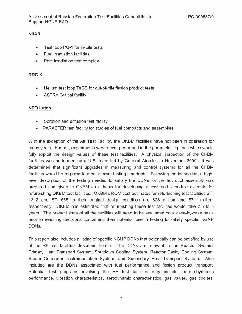
NIIAR
� Test loop PG-1 for in-pile tests � Fuel irradiation facilities � Post-irradiation test complex
RRC-KI
� Helium test loop TsGS for out-of-pile fission product tests � ASTRA Critical facility
NPO Lutch
� Sorption and diffusion test facility � PARAETER test facility for studies of fuel compacts and assemblies
With the exception of the Air Test Facility, the OKBM facilities have not been in operation for many years. Further, experiments were never performed in the parameter regimes which would fully exploit the design values of these test facilities. A physical inspection of the OKBM facilities was performed by a U.S. team led by General Atomics in November 2009. It was determined that significant upgrades in measuring and control systems for all the OKBM facilities would be required to meet current testing standards. Following the inspection, a high-level description of the testing needed to satisfy the DDNs for the hot duct assembly was prepared and given to OKBM as a basis for developing a cost and schedule estimate for refurbishing OKBM test facilities. OKBM’s ROM cost estimates for refurbishing test facilities ST-1312 and ST-1565 to their original design condition are $28 million and $7.1 million, respectively. OKBM has estimated that refurbishing these test facilities would take 2.5 to 3 years. The present state of all the facilities will need to be evaluated on a case-by-case basis prior to reaching decisions concerning their potential use in testing to satisfy specific NGNP DDNs. This report also includes a listing of specific NGNP DDNs that potentially can be satisfied by use of the RF test facilities described herein. The DDNs are relevant to the Reactor System, Primary Heat Transport System, Shutdown Cooling System, Reactor Cavity Cooling System, Steam Generator, Instrumentation System, and Secondary Heat Transport System. Also included are the DDNs associated with fuel performance and fission product transport. Potential test programs involving the RF test facilities may include thermo-hydraulic performance, vibration characteristics, aerodynamic characteristics, gas valves, gas coolers,

Assessment of Russian Federation Test Facilities Capabilities to Support NGNP R&D
PC-000587/0
vi
accident scenarios, and hot duct, as well as investigations of fuel performance and radionuclide transport and deposition.

Assessment of Russian Federation Test Facilities Capabilities to Support NGNP R&D
PC-000587/0
vii
TABLE OF CONTENTS
1. INTRODUCTION...............................................................................................................1
1.1. Background ...................................................................................................................1 1.2. Scope ............................................................................................................................2
2. NGNP DESIGN AND TECHNOLOGY DEVELOPMENT..................................................4
3. DESCRIPTION OF RF TEST FACILITIES .......................................................................7
3.1. OKBM Test Loops.........................................................................................................7 3.1.1. Steam Generator Model and High-Temperature HX Test Facility (ST-1312) ......7
3.1.2. Multipurpose Research Complex (ST-1565) ......................................................13
3.1.3. Air Test Facility...................................................................................................19
3.1.4. Main Circulator Test Facility (ST-1383)..............................................................22
3.1.5. Summary Table of OKBM Test Loops................................................................27
3.2. Test Facilities at NIIAR, RRC-KI and NPO Lutch to Support NGNP Technology
Development...............................................................................................................32
3.2.1. PG-1 Test Loop at NIIAR ...................................................................................32
3.2.2. NIIAR Test Facilities for Fuel Irradiation.............................................................33
3.2.3. Post-Irradiation Test Complex at NIIAR .............................................................38
3.2.4. TsGS Helium Test Loop at RRC-KI....................................................................39
3.2.5. ASTRA Critical Test Facility at RRC-KI..............................................................43
3.2.6. Sorption and Diffusion Test Facility at NPO Lutch .............................................46
3.2.7. ‘PARAMETER’ Test Facility at NPO Lutch.........................................................48
4. ASSESSMENT OF RF TEST FACILITIES TO SATISFY NGNP DDNS ........................51
5. POTENTIAL TEST PROGRAMS UTILIZING RF TEST FACILITIES ............................59
5.1. Preliminary Assessment of Candidate Test Programs for OKBM Test Facilities ........59 5.1.1. Study of Thermo-Hydraulic Performance and Flow Distribution ........................59
5.1.2. Investigation of Vibration Characteristics ...........................................................59
5.1.3. Structural Materials Testing................................................................................60
5.1.4. Aerodynamic Testing of Equipment ...................................................................60
5.1.5. Testing of Rotating Machinery with Bearings .....................................................60
5.1.6. Gas Valve Testing ..............................................................................................61

Assessment of Russian Federation Test Facilities Capabilities to Support NGNP R&D
PC-000587/0
viii
5.1.7. Gas Circulator Technology Development...........................................................61
5.1.8. Testing of Gas Coolers.......................................................................................61
5.1.9. Testing of Hot Duct.............................................................................................61
5.1.10. Investigation of Accident Scenarios .................................................................62
5.2. Candidate Test Programs with the Use of RRC-KI, NIIAR and NPO Lutch Facilities.62
6. QUALITY ASSURANCE NEEDS FOR THE RF FACILITIES ........................................63
7. CONCLUSIONS..............................................................................................................65
8. REFERENCES................................................................................................................66
APPENDIX A ............................................................................................................................ A-1
APPENDIX B ............................................................................................................................ B-1
APPENDIX C ............................................................................................................................ C-1

Assessment of Russian Federation Test Facilities Capabilities to Support NGNP R&D
PC-000587/0
ix
LIST OF FIGURES
Figure 2-1. NGNP Configuration with 750°C Reactor Outlet Helium Temperature .....................4�
Figure 2-2. GA NGNP Configuration for Technology Development Prior to October 2008 .........5�
Figure 3-1. High-Temperature Helium Facility for Heat-Exchange Equipment Tests ..................8�
Figure 3-2. Gas Circulator for the High-Temperature Helium Facility ..........................................8�
Figure 3-3. Simplified Flow Diagram of Helium Loop ST-1312....................................................9�
Figure 3-4. Schematic of the Steam-Water Loop at ST-1312 Facility........................................11�
Figure 3-5. Schematic Diagram of Air-Water Heat Exchange Model Tests ...............................14�
Figure 3-6. Flow Diagram of Steam Generator Model Tests .....................................................14�
Figure 3-7. Samples of Cooler Model for Finned Heat Exchange Surfaces ..............................15�
Figure 3-8. Schematic of helium loop at the Test Facility ST-1565 ...........................................15�
Figure 3-9. Gas circulator for the Multipurpose Research Complex ..........................................17�
Figure 3-10. Flow chart of Air Test Facility ................................................................................19�
Figure 3-11. Testing of a Recuperator Element at the Air Test Facility .....................................20�
Figure 3-12. Diagram of recuperator element blow-down..........................................................20�
Figure 3-13. Reactor Flow Model at the Air Test Facility ...........................................................21�
Figure 3-14. Main Circulator Test Facility ..................................................................................22�
Figure 3-15. Gas Circulator Pilot Sample ..................................................................................23�
Figure 3-16. Simplified Flow Diagram of the Gas Circulator Test Facility..................................24�
Figure 3-17. Diagram of the PG-1 loop facility...........................................................................32�
Figure 3-18. Horizontal Cross-Section of SM-3 Research Reactor ...........................................35�
Figure 3-19. Cross-Section View of RBT-6 Reactor Core .........................................................36�
Figure 3-20. Diagrams of Irradiation Devices at NIIAR..............................................................37�
Figure 3-21. NIIAR Irradiation Gas Sampling Test Facility Diagram..........................................38�
Figure 3-22. Laboratory Equipment for Hot-Cell Tests at NIIAR................................................39�
Figure 3-23. TsGS Test Loop at RRC-KI ...................................................................................40�
Figure 3-24. Schematic Diagram of TsGS Test Loop ................................................................42�
Figure 3-25. Critical Assembly with Annular Core Simulating GT-MHR Physical Features.......44�
Figure 3-26. Cross Section of ASTRA Facility Set Up for Hot Critical Experiments ..................46�
Figure 3-27. Experimental Setup at NPO Lutch for Sorption and Diffusion Process Studies ....47�
Figure 3-28. Control Room of PARAMETER Test Facility at NPO Lutch ..................................49�

Assessment of Russian Federation Test Facilities Capabilities to Support NGNP R&D
PC-000587/0
x
LIST OF TABLES
Table 3-1. Summary of OKBM Helium and Air Test Loops .......................................................28�
Table 3-2. Technical Parameters of the PG-1 Loop ..................................................................33�
Table 3-3. Parameters of the loop channel in PG-1 circuit of 'MIR' reactor ...............................33�
Table 3-4. Characteristics of NIIAR Research Reactors............................................................34�
Table 3-5. Main Technical Characteristics of Upgraded TsGS Test Facility..............................41�
Table 3-6. Main Technical Characteristics of ASTRA Critical Facility........................................45�
Table 3-7. Technical Characteristics of NPO Lutch Sorption and Diffusion Test Facility...........48�
Table 3-8. Technical Characteristics of NPO Lutch PARAMETER Test Facility.......................50�
Table 4-1. NGNP Design Data Needs Relevant to Capabilities of OKBM Facilities ..................52�
Table 4-2. NGNP DDNs Relevant to Capabilities of Other RF Facilities ...................................57�

Assessment of Russian Federation Test Facilities Capabilities to Support NGNP R&D
PC-000587/0
xi
ACRONYMS AND ABBREVIATIONS ASTRA Critical Facility for Reactor Physics Studies (Russian) BEA Battelle Energy Alliance CFP Coated Fuel Particle CPS Control and Protection System CR Control Rod CTC Component Test Capability DDN Design Data Need DGS Dry Gas Seal EMB Electromagnetic Bearing ETF Electromagnetic Bearing Testing Facilities FA Fuel Assembly FPT Fission Product Transport GA General Atomics GT-MHR Gas Turbine – Modular Helium Reactor HPTF High Pressure Test Facility HTE High Temperature Electrolysis HTGR High Temperature Gas-Cooled Reactor HX Heat Exchanger ID Irradiation Device IHX Intermediate Heat Exchanger INL Idaho National Laboratory IPS Investment Protection System NPO Lutch Science and Industry Complex Lutch (Russian) NNSA National Nuclear Security Administration NGNP Next Generation Nuclear Plant NIIAR Scientific Research Institute for Atomic Reactors (Russian) OKBM Experimental Design Bureau of Machine Building (Russian) PCDIS Plant Control, Data, and Instrumentation System PCS Power Conversion System PHC Primary Helium Circulator PHTS Primary Heat Transport System PIE Post Irradiation Examination PIH Post Irradiation Heating QA Quality Assurance R/B Release Rate / Birth Rate RCCS Reactor Cavity Cooling System
Assessment of Russian Federation Test Facilities Capabilities to Support NGNP R&D
PC-000587/0
xii
RF Russian Federation RI Reactor Internals RN Radionuclide ROM Rough Order of Magnitude RPS Reactor Protection System RRC-KI Russian Research Center - Kurchatov Institute RS Reactor System RSM Rotor Scale Model RSSM Reactor Shutdown System Materials SCS Shutdown Cooling System SCHE Shutdown Cooling Heat Exchanger SG Steam Generator SHE Shut Down Heat Exchanger SHTS Secondary Heat Transport System S-I Sulfur-Iodine SLSV Shutdown Circulator Loop Shut-off Valve SSC System, Structure, and Components STF Seal Testing Facilities TBD To Be Determined UCR Upper Core Restraint UPS Upper Plenum Shroud US DOE United States Department Of Energy VHTR Very High Temperature Reactor VS Vessel System VVER Water-Water Power Reactor (Russian) WPu Weapons Grade Plutonium

Assessment of Russian Federation Test Facilities Capabilities to Support NGNP R&D
PC-000587/0
1
1. INTRODUCTION
1.1. Background The Next Generation Nuclear Plant (NGNP) Project was established by the Energy Policy Act of 2005. The Very High Temperature Reactor (VHTR) was the original design concept of choice to satisfy the NGNP mission of high-efficiency co-generation of electricity and process heat for hydrogen production. The NGNP program is led by Idaho National Laboratory (INL) under the direction of the US Department of Energy (US DOE). The NGNP’s mission has been evolving since it was originally conceived and the current objective of the NGNP Project is to deploy HTGR technology to satisfy the near-term need of U.S. industries for co-generation of electricity and process steam. These industries include petrochemical, coal-to-liquids, fertilizers and ammonia, oil sands/oil shale, and petroleum refining. The target startup time for NGNP is currently 2021. The NGNP Project has significant potential for international collaboration to meet its technology development requirements, especially for HTGR designs having a reactor outlet helium temperature of 950°C. The on-going direct-cycle, modular High Temperature Gas-Cooled Reactor (HTGR) program for disposal of weapons grade plutonium (WPu) in the Russian Federation (RF), referred to as the Gas-Turbine Modular Helium Reactor (GT-MHR) program, shares a number of common Design Data Needs (DDNs) with proposed NGNP reactor designs. These DDNs are primarily related to fuel, fission product transport, and graphite, but the NGNP and GT-MHR projects also have common technology development needs associated with the reactor system, pressure vessel, and power conversion systems (Ref. 1). In addition, the computational models and computer simulations are also relatively similar between the RF GT-MHR and NGNP programs. The GT-MHR Program to develop a direct-cycle, prismatic core design was started as a private initiative between General Atomics (GA) and Minatom of Russia in 1993, and became a joint technology development program of the National Nuclear Security Administration (NNSA) and Rosatom in 1998 to meet both nations’ commitments towards reduction of nuclear weapons stockpiles. Afrikantov OKB Mechanical Engineering (OKBM), based in Nizhny Novgorod, was given the responsibility of being the integrating contractor for GT-MHR design development in the RF. OKBM is also the chief designer of this reactor. In connection with the GT-MHR Program, OKBM has built a number of experimental facilities to test various components; these facilities have been funded on a cost-share basis with NNSA. Prior to the GT-MHR Program, HTGR research and development efforts were carried out in the RF since the late 1960’s at a number of facilities. In the 1980’s, the HTGR work in the RF was
Assessment of Russian Federation Test Facilities Capabilities to Support NGNP R&D
PC-000587/0
2
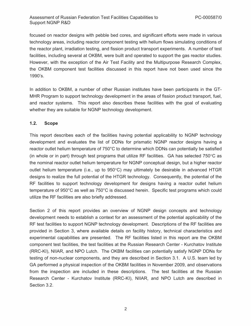
focused on reactor designs with pebble bed cores, and significant efforts were made in various technology areas, including reactor component testing with helium flows simulating conditions of the reactor plant, irradiation testing, and fission product transport experiments. A number of test facilities, including several at OKBM, were built and operated to support the gas reactor studies. However, with the exception of the Air Test Facility and the Multipurpose Research Complex, the OKBM component test facilities discussed in this report have not been used since the 1990’s. In addition to OKBM, a number of other Russian institutes have been participants in the GT-MHR Program to support technology development in the areas of fission product transport, fuel, and reactor systems. This report also describes these facilities with the goal of evaluating whether they are suitable for NGNP technology development. 1.2. Scope This report describes each of the facilities having potential applicability to NGNP technology development and evaluates the list of DDNs for prismatic NGNP reactor designs having a reactor outlet helium temperature of 750°C to determine which DDNs can potentially be satisfied (in whole or in part) through test programs that utilize RF facilities. GA has selected 750�C as the nominal reactor outlet helium temperature for NGNP conceptual design, but a higher reactor outlet helium temperature (i.e., up to 950�C) may ultimately be desirable in advanced HTGR designs to realize the full potential of the HTGR technology. Consequently, the potential of the RF facilities to support technology development for designs having a reactor outlet helium temperature of 950°C as well as 750°C is discussed herein. Specific test programs which could utilize the RF facilities are also briefly addressed. Section 2 of this report provides an overview of NGNP design concepts and technology development needs to establish a context for an assessment of the potential applicability of the RF test facilities to support NGNP technology development. Descriptions of the RF facilities are provided in Section 3, where available details on facility history, technical characteristics and experimental capabilities are presented. The RF facilities listed in this report are the OKBM component test facilities, the test facilities at the Russian Research Center - Kurchatov Institute (RRC-KI), NIIAR, and NPO Lutch. The OKBM facilities can potentially satisfy NGNP DDNs for testing of non-nuclear components, and they are described in Section 3.1. A U.S. team led by GA performed a physical inspection of the OKBM facilities in November 2009, and observations from the inspection are included in these descriptions. The test facilities at the Russian Research Center - Kurchatov Institute (RRC-KI), NIIAR, and NPO Lutch are described in Section 3.2.

Assessment of Russian Federation Test Facilities Capabilities to Support NGNP R&D
PC-000587/0
3
An assessment of the RF facilities to satisfy NGNP DDNs is provided in Section 4, where relevant NGNP DDNs are listed and coupled with the appropriate facilities discussed in the report. Section 5 identifies NGNP test programs that could potentially be conducted in the RF facilities.
Assessment of Russian Federation Test Facilities Capabilities to Support NGNP R&D
PC-000587/0
4
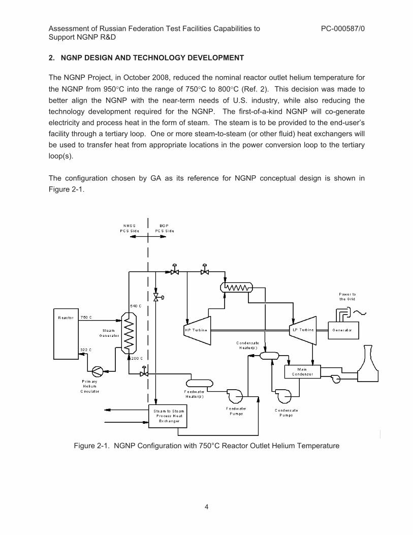
2. NGNP DESIGN AND TECHNOLOGY DEVELOPMENT The NGNP Project, in October 2008, reduced the nominal reactor outlet helium temperature for the NGNP from 950�C into the range of 750�C to 800�C (Ref. 2). This decision was made to better align the NGNP with the near-term needs of U.S. industry, while also reducing the technology development required for the NGNP. The first-of-a-kind NGNP will co-generate electricity and process heat in the form of steam. The steam is to be provided to the end-user’s facility through a tertiary loop. One or more steam-to-steam (or other fluid) heat exchangers will be used to transfer heat from appropriate locations in the power conversion loop to the tertiary loop(s). The configuration chosen by GA as its reference for NGNP conceptual design is shown in Figure 2-1.
Figure 2-1. NGNP Configuration with 750°C Reactor Outlet Helium Temperature
Assessment of Russian Federation Test Facilities Capabilities to Support NGNP R&D
PC-000587/0
5
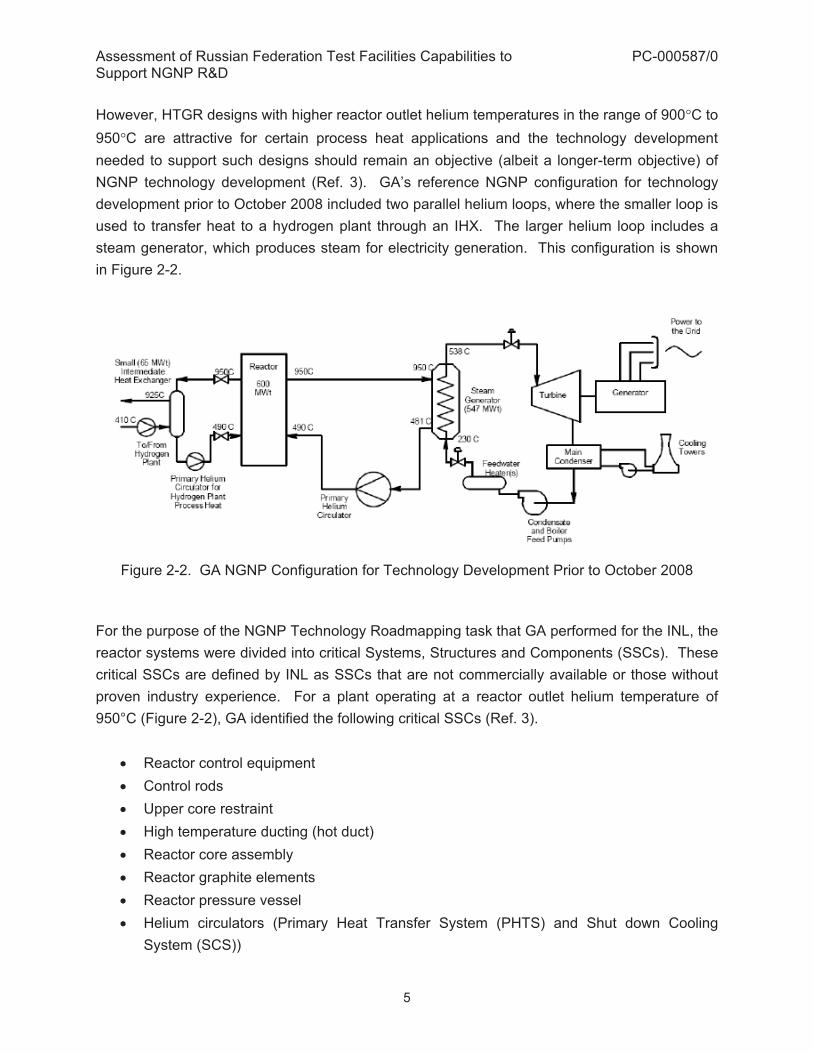
However, HTGR designs with higher reactor outlet helium temperatures in the range of 900�C to 950�C are attractive for certain process heat applications and the technology development needed to support such designs should remain an objective (albeit a longer-term objective) of NGNP technology development (Ref. 3). GA’s reference NGNP configuration for technology development prior to October 2008 included two parallel helium loops, where the smaller loop is used to transfer heat to a hydrogen plant through an IHX. The larger helium loop includes a steam generator, which produces steam for electricity generation. This configuration is shown in Figure 2-2.
Figure 2-2. GA NGNP Configuration for Technology Development Prior to October 2008
For the purpose of the NGNP Technology Roadmapping task that GA performed for the INL, the reactor systems were divided into critical Systems, Structures and Components (SSCs). These critical SSCs are defined by INL as SSCs that are not commercially available or those without proven industry experience. For a plant operating at a reactor outlet helium temperature of 950°C (Figure 2-2), GA identified the following critical SSCs (Ref. 3).
� Reactor control equipment � Control rods � Upper core restraint � High temperature ducting (hot duct) � Reactor core assembly � Reactor graphite elements � Reactor pressure vessel � Helium circulators (Primary Heat Transfer System (PHTS) and Shut down Cooling
System (SCS))

Assessment of Russian Federation Test Facilities Capabilities to Support NGNP R&D
PC-000587/0
6
� Intermediate Heat Exchanger (IHX) � Shutdown Cooling Heat Exchanger (SCHE) � Reactor Cavity Cooling System (RCCS) � Steam generator (SG) � Turbomachinery (for direct combined-cycle Power Conversion System (PCS)) � High temperature valves � Sulfur Iodine (S-I) hydrogen production system � Fuel handling and storage system � Primary circuit and balance of plant instrumentation � Reactor Protection System (RPS), Investment Protection System (IPS), and Plant
Control, Data, and Instrumentation System (PCDIS) � Fuel
Three of these SSCs are not included in the new NGNP configuration shown in Figure 2-1, namely the IHX, the turbomachinery (for a combined-cycle PCS), and the S-I hydrogen production system. However, the test facilities should provide the capability for testing the IHX, turbomachinery subsystems, and, to some extent, hydrogen production systems (although not necessarily the S-I system). The test facilities described in this report are applicable to the various SSCs listed above. In particular, the applicable components and systems include fuel, reactor core, RCCS, reactor pressure vessel, helium circulators, shutdown cooling heat exchanger, steam generator and high-temperature valves, IHX, high-temperature ducting, and other systems and components.

Assessment of Russian Federation Test Facilities Capabilities to Support NGNP R&D
PC-000587/0
7
3. DESCRIPTION OF RF TEST FACILITIES 3.1. OKBM Test Loops OKBM has been associated with the development of gas cooled reactors in the RF since the 1980s. In connection with this work (independent of the current GT-MHR technology development for WPu disposition); OKBM has built several flow loops for testing of HTGR components. This section describes four test loops at OKBM facilities, located at Nizhny Novgorod. These facilities were identified at the onset of this study as being potentially useful to satisfy a number of NGNP DDNs. The subsections of this section address the details associated with each specific OKBM test loop, and another subsection provides a summary table of all four loops, which is complementary to the preceding descriptions. In addition to the four test loops discussed here, there are other test facilities designed at OKBM with joint US and RF funding that can be useful for NGNP development, especially for electro magnetic bearings (EMBs) and seals. These are the Electromagnetic Bearing Testing Facilities (ETF) and Seal Test Facilities (STF). They are briefly described in Appendix A. Also included in Appendix A is a description of a test facility for dry gas seals (DGS), which can be useful for potential development of the circulator with an external motor. 3.1.1. Steam Generator Model and High-Temperature HX Test Facility (ST-1312) The ST-1312 test facility for Steam Generator Model and High Temperature Heat Exchanger (HX) was commissioned in 1988 and was used for testing of steam generator models starting in 1991. The facility was designed such that it would be capable of testing large-size (test cell is 24.6 x 16.8 x 17.1 m) steam generator models and heat exchanger models for high-temperature helium cooled reactor plants. The steam generator model and high-temperature heat-exchanger facility is shown in Figure 3-1, and the gas circulator associated with this facility is shown in Figure 3-2. The gas circulator power is 0.4 MW.

Assessment of Russian Federation Test Facilities Capabilities to Support NGNP R&D
PC-000587/0
8
Figure 3-1. High-Temperature Helium Facility for Heat-Exchange Equipment Tests
Figure 3-2. Gas Circulator for the High-Temperature Helium Facility A simplified flow sheet of this test loop is shown in Figure 3-3.

Assessment of Russian Federation Test Facilities Capabilities to Support NGNP R&D
PC-000587/0
9
Figure 3-3. Simplified Flow Diagram of Helium Loop ST-1312
This facility is capable of studying thermal hydraulic and vibration performance of the steam generators and heat exchangers, as well as the effects of high temperatures on the structural materials. With respect to testing heat exchangers at this test facility, these specific tests have not yet been performed, but such experiments can be arranged within existing capabilities. The test facility includes a direct current power supply system, water recycling system, acoustic emission monitoring diagnostic system, and TV monitoring, as well as the data acquisition, processing and display system (henceforth referred to as “information-measuring” system). The facility equipment is located within a protective reinforced concrete structure. Control of facility operations can be done either from the central control room or the local control stations. Depending upon operation requirements, the electrical power can be continuously adjusted in the range of 5 to 100% power. The total electric power available is 17 MW. This facility has a heating capacity up to 15 MW. The hot helium is used to produce steam in the steam generator with a heating requirement of 10 MW. The helium enters the steam generator at 750�C and exits at 342°C. The steam generator is a helical bundle type. The size of its vessel is approximately 1 m diameter and 3 m height. A different steam generator vessel could in principle be placed into this loop (if required), but it has to fit the flange with 460 mm inner diameter and 990 mm outer diameter. The size of a new steam generator would be limited by the heating capacity of this loop. A large amount of the energy is recovered in the
Assessment of Russian Federation Test Facilities Capabilities to Support NGNP R&D
PC-000587/0
10
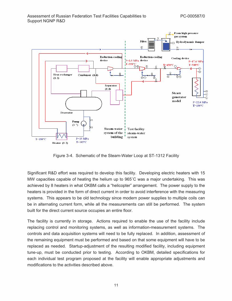
recuperator by heating the outlet helium from the circulator using the outlet helium from the steam generator. The heat rejection capability is up to 5 MW. The operating temperature range is broad – from 350°C to 965°C, and the volumetric helium flow rate can be up to 4000 m3/h at 5 MPa. The test cell size is 24.6 x 16.8 x 17.1 m, and a test article placed into the facility can be up to 1.5 m in diameter and 10 m in height, with vertical orientation. The test facility contains a helium loop, distilled water loop, and a recyclable water loop. At the steam generator model, this test loop has the following steam parameters:
� maximum steam temperature: 540°C, � feed water temperature: 180°C � feed water pressure: 22.0 MPa � outlet steam pressure: 17.6 MPa, � maximum flow rate: 5.55 kg/s
The thermal input to this steam generator model is 10 MW. Flow rates of helium and feed water are adjustable. Steam isolation valve testing is possible under the arrangement of this experimental facility. A schematic of the steam-water loop at the ST-1312 facility is shown in Figure 3-4.
Assessment of Russian Federation Test Facilities Capabilities to Support NGNP R&D
PC-000587/0
11
Figure 3-4. Schematic of the Steam-Water Loop at ST-1312 Facility Significant R&D effort was required to develop this facility. Developing electric heaters with 15 MW capacities capable of heating the helium up to 965�C was a major undertaking. This was achieved by 8 heaters in what OKBM calls a “helicopter” arrangement. The power supply to the heaters is provided in the form of direct current in order to avoid interference with the measuring systems. This appears to be old technology since modern power supplies to multiple coils can be in alternating current form, while all the measurements can still be performed. The system built for the direct current source occupies an entire floor. The facility is currently in storage. Actions required to enable the use of the facility include replacing control and monitoring systems, as well as information-measurement systems. The controls and data acquisition systems will need to be fully replaced. In addition, assessment of the remaining equipment must be performed and based on that some equipment will have to be replaced as needed. Startup-adjustment of the resulting modified facility, including equipment tune-up, must be conducted prior to testing. According to OKBM, detailed specifications for each individual test program proposed at the facility will enable appropriate adjustments and modifications to the activities described above.
Assessment of Russian Federation Test Facilities Capabilities to Support NGNP R&D
PC-000587/0
12
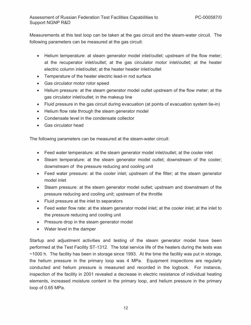
Measurements at this test loop can be taken at the gas circuit and the steam-water circuit. The following parameters can be measured at the gas circuit:
� Helium temperature: at steam generator model inlet/outlet; upstream of the flow meter; at the recuperator inlet/outlet; at the gas circulator motor inlet/outlet; at the heater electric column inlet/outlet; at the heater header inlet/outlet
� Temperature of the heater electric lead-in rod surface � Gas circulator motor rotor speed � Helium pressure: at the steam generator model outlet upstream of the flow meter; at the
gas circulator inlet/outlet; in the makeup line � Fluid pressure in the gas circuit during evacuation (at points of evacuation system tie-in) � Helium flow rate through the steam generator model � Condensate level in the condensate collector � Gas circulator head
The following parameters can be measured at the steam-water circuit:
� Feed water temperature: at the steam generator model inlet/outlet; at the cooler inlet � Steam temperature: at the steam generator model outlet; downstream of the cooler;
downstream of the pressure reducing and cooling unit � Feed water pressure: at the cooler inlet; upstream of the filter; at the steam generator
model inlet � Steam pressure: at the steam generator model outlet; upstream and downstream of the
pressure reducing and cooling unit; upstream of the throttle � Fluid pressure at the inlet to separators � Feed water flow rate: at the steam generator model inlet; at the cooler inlet; at the inlet to
the pressure reducing and cooling unit � Pressure drop in the steam generator model � Water level in the damper
Startup and adjustment activities and testing of the steam generator model have been performed at the Test Facility ST-1312. The total service life of the heaters during the tests was ~1000 h. The facility has been in storage since 1993. At the time the facility was put in storage, the helium pressure in the primary loop was 4 MPa. Equipment inspections are regularly conducted and helium pressure is measured and recorded in the logbook. For instance, inspection of the facility in 2001 revealed a decrease in electric resistance of individual heating elements, increased moisture content in the primary loop, and helium pressure in the primary loop of 0.65 MPa.

Assessment of Russian Federation Test Facilities Capabilities to Support NGNP R&D
PC-000587/0
13
OKBM evaluation of the test facility condition suggested that the system which will most likely require upgrading and/or equipment replacement is the helium storage and transfer system, including helium injection, storage, makeup, removal and initial purification. The information-measuring, control, and monitoring systems, as well as the power source, are considered outdated and obsolete. A physical inspection of Test Facility ST-1312 was conducted by the U.S. team on 11/27/09. Observations from the visit revealed that much of the support equipment, along with the measurement, data acquisition, and control systems are obsolete. This test facility is located within the OKBM secure zone, which presents a potential problem with respect to future access. A possible solution to the access issue might be moving the facility outside the secure zone, but such a move will be expensive, time consuming, and difficult given the very large size of the facility (five stories high). This test facility was last used in 1993, and its refurbishment for new experiments will likely require a considerable effort. However, since this is a very large helium loop, it could be useful for NGNP technology development. OKBM has provided a ROM cost estimate for refurbishing Test Facility ST-1312. The total estimated amount is ~$28 million. The estimate is based on the following breakdown:
� Costs for documentation development, including project management and licensing - $4.1 million
� Costs for dismantling and installation activities - $6.2 million � Equipment cost - $17.7 million.
OKBM estimates that approximately 2.5 to 3 years would be needed to restore this facility to its design condition. OKBM’s cost and schedule estimate is provided in Appendix C. 3.1.2. Multipurpose Research Complex (ST-1565) The ST-1565 multipurpose facility was commissioned in 1984 as part of the work on HTGR projects, and it was used for thermo-hydraulics studies of the GT-MHR recuperator heat-exchanging elements, cooler pipe clusters, safety complex, thermal insulation, high temperature helium heaters, small helium circulators, steam generator modules, and by-pass valves. A schematic of the air-water heat exchange model tests at this facility is shown in Figure 3-5. A flow diagram of steam generator model tests is shown in Figure 3-6. The cooler model samples of finned heat exchanger surfaces are shown in Figure 3-7.

Assessment of Russian Federation Test Facilities Capabilities to Support NGNP R&D
PC-000587/0
14
Figure 3-5. Schematic Diagram of Air-Water Heat Exchange Model Tests
Figure 3-6. Flow Diagram of Steam Generator Model Tests

Assessment of Russian Federation Test Facilities Capabilities to Support NGNP R&D
PC-000587/0
15
Figure 3-7. Samples of Cooler Model for Finned Heat Exchange Surfaces A simplified schematic diagram of the helium loop is shown in Figure 3-8.
Figure 3-8. Schematic of helium loop at the Test Facility ST-1565

Assessment of Russian Federation Test Facilities Capabilities to Support NGNP R&D
PC-000587/0
16
This facility was originally designed for testing the steam generator and heat exchange module thermo-hydraulic performance. It can be used to investigate accident scenarios associated with loss of pressure in the primary coolant as well as temperature changes due to water ingress in the primary circuit. The entire facility is located within a metal cell. The facility is controlled from a control room, which is isolated and protected from the main equipment. Helium and air are heated by electric heaters. This test facility consists of three primary and two secondary loops. The main loops are the helium loop, steam-water loop, and air loop. The secondary loops include the return-water loop and distilled water loop. The facility can be used for studies of air-helium, helium-helium, air-water, and helium-water heat exchangers. Test facility ST-1565 is equipped with a helium purification system to maintain the purity of the helium. This facility can support a gas volumetric flow rate of up to 50 m3/h (100gm/s), and gas pressures of up to 5 MPa. Helium temperatures as high as 965°C can be achieved. Both heating capacity and heat rejection capability can reach 0.25 MW. The size of the steel test cell is 10.0 x 10.0 x 6.0 m, and a test articles with diameters up to 0.5 m and height up to 3 m can be placed in it with vertical positioning. The available electric power is 0.3 MW. The volume of the main helium loop is 500 liters. The steam-water loop can produce steam at 20.6 MPa and 540°C, at the rate of 0.44 kg/s. The air loop is equipped with an electric heater of 100 kW, and its flow rate is 180 gm/s. The air pressure is 0.6 MPa, and the temperature can be as high as 510°C. The gas circulator in this facility is of relatively small power of 0.03 MW (Figure 3-9).

Assessment of Russian Federation Test Facilities Capabilities to Support NGNP R&D
PC-000587/0
17
Figure 3-9. Gas circulator for the Multipurpose Research Complex No tests are currently conducted at the facility, but its systems are still active. The facility adjustments for conducting new tests will depend on the detailed specifications for the proposed test programs. Measurements at this test loop can be taken at the helium circuit, air circuit, and steam-water circuit. The following parameters can be measured at the helium circuit:
� Helium temperature: at the heater inlet/outlet; at the model inlet/outlet; at the gas circulator inlet/outlet; at the cooler inlet/outlet
� Helium pressure: at the model inlet; upstream and downstream of the reducing unit; in the relief pipeline; helium pressure drop in the model
� Helium flow rate in the pipeline (between the gas circulator and the heater) The air circuit, the parameters that can be measured are:
� Air temperature: at the model inlet/outlet; at the air heater inlet/outlet � Air pressure: at the model outlet; at the heater inlet; upstream of the flow meter � Air pressure losses: in the heater; in the model; in the filters � Air flow rate through the model (downstream the model)
The following parameters can be measured at the steam-water circuit:
� Feed water temperature: at the model inlet; at the condenser outlet; at the pump inlet; at the heater outlet

Assessment of Russian Federation Test Facilities Capabilities to Support NGNP R&D
PC-000587/0
18
� Steam temperature: at the model outlet; at the condenser inlet � Feed water pressure at the model inlet � Pressure drop in the model � Steam pressure: at the model outlet; at the condenser inlet � Pressure in the inlet � Feed water flow rate: at the model inlet; at the steam cooler � Water level in the constant header tank � Nitrogen pressure in the pressurizer and in the constant header tank
The following tests have been performed at the Test Facility ST-1565 since it was put into operation – steam generation model; valves and safety devices; high-temperature helium heaters; high-temperature insulation; helium coolers; helium-air recuperator heat exchanger elements; and air-water cooler heat exchange elements. OKBM’s evaluation of the test facility stated it was last configured for air-water heat exchanger element tests. The helium loop is operable but the circulator requires maintenance. The air loop and distilled power loop are operable as well. The power supply system can also be operated. However, the steam-water system has been dismantled. The information measurement, control, and monitoring systems need upgrading. A physical inspection of the Test Facility ST-1565 was conducted by the U.S. team on 11/27/09. The loop was last operated in 2004. Overall, the facility does not presently appear to be ready for operations without upgrades. In particular, the steam-water system has been dismantled. The helium purification system needs extensive repairs. The gas circulator needs maintenance. The entire information measurement, data storage, and control systems need replacement. The arrangement of the loop is very crowded. GA believes that this multipurpose research complex could become useful for NGNP technology development, but only after upgrade efforts. OKBM has provided a ROM cost estimate for refurbishing Test Facility ST-1565. The total estimated cost is ~$7.1 million. The estimate is based on the following breakdown:
� Costs for documentation development, including project management and licensing - $1.4 million
� Costs for dismantling and installation activities - $1.6 million � Equipment cost - $4.1 million.
OKBM estimates that approximately 2.5 to 3 years would be needed to restore this facility to its design condition. OKBM’s cost and schedule estimate is provided in Appendix C.
Assessment of Russian Federation Test Facilities Capabilities to Support NGNP R&D
PC-000587/0
19
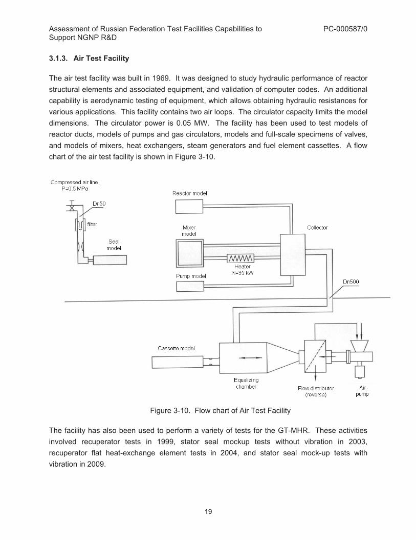
3.1.3. Air Test Facility The air test facility was built in 1969. It was designed to study hydraulic performance of reactor structural elements and associated equipment, and validation of computer codes. An additional capability is aerodynamic testing of equipment, which allows obtaining hydraulic resistances for various applications. This facility contains two air loops. The circulator capacity limits the model dimensions. The circulator power is 0.05 MW. The facility has been used to test models of reactor ducts, models of pumps and gas circulators, models and full-scale specimens of valves, and models of mixers, heat exchangers, steam generators and fuel element cassettes. A flow chart of the air test facility is shown in Figure 3-10.
Figure 3-10. Flow chart of Air Test Facility
The facility has also been used to perform a variety of tests for the GT-MHR. These activities involved recuperator tests in 1999, stator seal mockup tests without vibration in 2003, recuperator flat heat-exchange element tests in 2004, and stator seal mock-up tests with vibration in 2009.

Assessment of Russian Federation Test Facilities Capabilities to Support NGNP R&D
PC-000587/0
20
Figure 3-11 shows testing of a recuperator element at the Air Test Facility.
Figure 3-11. Testing of a Recuperator Element at the Air Test Facility A simplified diagram of a recuperator element blow-down on the low-pressure side with supply of water on the high-pressure side is shown in Figure 3-12.
4
1
3
6
5
2
1 –recuperator heat exchange element model; 2 – manual pump;
3 – filter - cyclone; 4 – mesh filter; 5 – air inlet; 6 – air outlet
Figure 3-12. Diagram of recuperator element blow-down

Assessment of Russian Federation Test Facilities Capabilities to Support NGNP R&D
PC-000587/0
21
The air test facility capabilities include testing the reactor flow ducts models. These models enable obtaining hydraulic resistance and flow distribution between different sections. A reactor flow model at the Air Test Facility is shown in the Figure 3-13. The model diameter is 1.2 m, its length is 4 m, and it has 80 test points.
Figure 3-13. Reactor Flow Model at the Air Test Facility The air flow rate at the Air Test Facility can be as high as 3.3 kg/s, and the pressure head is 0.005 MPa. This pressure head (or pressure drop) is required to enable the flow. The actual operating pressure is atmospheric. Temperatures up to 360�C can be reached. Both heating and cooling capacity are about 0.1 MW. The test cell dimensions are 15 x 4 x 4 m. Total electrical power available at the facility is 0.1 MW. The circulator capacity is 30 kW and heater capacity is 35 kW. Control and data acquisition systems at the Air Test Facility are re-configured in accordance with each particular test model, depending on a specific test objective and scope. The facility is currently in regular use. In order to estimate the time and cost of adjustment and modifications for conducting new tests at this facility, detailed specifications of the tests are required. The following tests have been performed at the Air Test Facility since it was put into operation – reactor flow ducts; pumps and gas circulator models; valves; and models of mixers, steam generators, fuel elements and heat exchangers, and recuperator and stator seals. OKBM stated the Air Test Facility is currently in operation. However, the data acquisition, measuring, and control system need to be updated.

Assessment of Russian Federation Test Facilities Capabilities to Support NGNP R&D
PC-000587/0
22
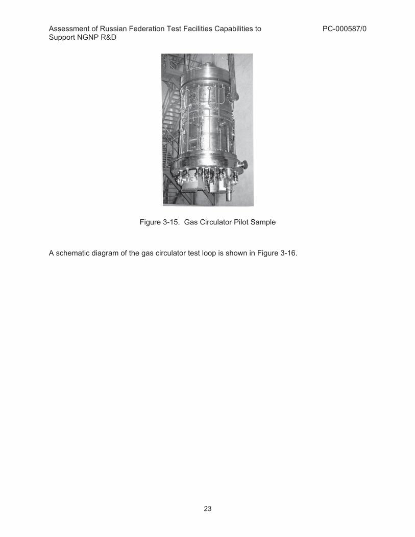
A physical inspection of the Air Test Facility by the U.S. team was conducted on 11/26/09. It was ascertained that this facility is in working condition and can be re-configured to accommodate a variety of test models. The information measuring system, information transfer system, and data storage and control systems are all in working condition, although they would need to be modernized to meet U.S. standards. GA believes that the Air Test Facility can be used in its present condition to study valves, flow ducts, and heat exchanger modules. The control system and data acquisition system should be upgraded, but this can likely be done at minimal cost. 3.1.4. Main Circulator Test Facility (ST-1383) The Main Circulator Test Facility was designed to test the pilot sample of the main helium circulator and shutoff valve for the reactor plant VG-400. Testing at this facility confirmed compatibility of the gas circulator motor with the massive asynchronous rotor and the static frequency converter. Experimental data has been obtained for further upgrade of the main gas circulator. The tune up and start up adjustment of this test facility was completed in 1991-1992. The Main Circulator test facility and the gas circulator pilot sample are shown in Figure 3-14 and Figure 3-15, respectively.
Figure 3-14. Main Circulator Test Facility
Assessment of Russian Federation Test Facilities Capabilities to Support NGNP R&D
PC-000587/0
23
Figure 3-15. Gas Circulator Pilot Sample A schematic diagram of the gas circulator test loop is shown in Figure 3-16.

Assessment of Russian Federation Test Facilities Capabilities to Support NGNP R&D
PC-000587/0
24
1 - Gas-oil separator; 2 – Oil tanks; 3 – Vessel; 4 – Bypass; 5 – Inlet pipe; 6 – Cooler; 7 – Valve; 8 – Water pump; 9, 10, 13 – Filters; 11 – Electric gas circulator; 12 – Coolers; 14 – Oil pumps; 15 – Oil container
Figure 3-16. Simplified Flow Diagram of the Gas Circulator Test Facility The main gas circulator has a nominal volumetric flow rate of 24.6 m3/s, temperature of 342°C and pressure of 4.9 MPa. The volumetric flow rate can be up to 34 m3/s at a temperature up to 400°C. The circulator power is 6.3 MW. Its weight is 55,000 kg. The rotation speed is in the range of 600 to 6000 RPM. In the actual reactor plant arrangement, the gas circulator would be below the reactor vessel. In the test facility arrangement, the gas circulator is vertically located below the circulation loop vessel. Such an arrangement required manufacturing and tune-up of special mounting and dismounting equipment. This centrifugal circulator is powered by a built-in electric motor. The

Assessment of Russian Federation Test Facilities Capabilities to Support NGNP R&D
PC-000587/0
25
circulator vessel has a cooler attached to its side at the top, along with supports with thermal insulation, labyrinth seals and guidance device. At the bottom, the vessel has a special sealed cover with electric lead-ins, appropriate connections for pipelines of the servicing systems, and tachometric sensors. The electric motor is cooled by helium through a built-in gas circulator cooling system. The rotor of the electric motor rotates on two radial hydrostatic bearings and one axial hydrodynamic bearing. Its design permits installation of electromagnetic and catcher bearings as necessary. The rotor is supported by oil bearings. The electric motor is in a helium environment. The main part of the circulator consists of an inlet, working wheel, and a guidance device. The cutoff valve made as a circular drum allows for a rapid turn-off of helium circulation in the reactor primary loop in case of accident scenarios. It also serves to limit a reverse helium flow in the loop when it stops. The automatic control of the cutoff valve is performed by the reactor plant control system. A significant amount of R&D work preceded the creation of the main gas circulator. Its development required special testing on a unit-by-unit basis. Preliminary testing was done on specially designated models, mockups, and special test facilities. The circulator was tested for its aero-dynamic characteristics, bearing performance, cut-off valve function, as well as the work of the static frequency converter. This preliminary testing validated design concepts of the gas circulator. The entire gas loop volume is 41.5 m3; pressure is 4.9 MPa. The heat removal capacity is 1.01 MW at temperatures up to 400°C. The protection box volume is 9,000 m3. The facility contains a helium loop, recyclable water loop, and vacuum and ventilation systems. The main gas circulator test facility is cooled by water, and the cooling water pressure is 0.6 MPa. The oil system of the main circulator test facility has an oil volume of 6.0 m3. The oil feed is 50 m3 / hr. The pressure head in the oil system is 250 m of oil, and the pump pressure is 7.0 MPa. The total electrical power available at the main circulator test facility is 6.5 MW. This facility was designed for rotation up to 5600 RPM, but the testing conducted to date has been limited to 600 RPM. Further testing was not conducted due to elimination of government funding for this program. Test facility ST-1383 allows testing of the gas-dynamic and thermal characteristics of various types of gas circulators, including all of the technical characteristics of the circulator, along with electromechanical parameters of the electric motor which has the rotor rotation frequency control system. OKBM has stated that this facility could also be used for testing of large electro magnetic and catcher bearings.

Assessment of Russian Federation Test Facilities Capabilities to Support NGNP R&D
PC-000587/0
26
The maximum size of the test article placed in this facility can be up to 4 m in diameter, and 8 m in height. The weight of an article can be up to 60,000 kg. For this facility, measurements can be taken within the following systems: Gas System; Oil System; Cooling System and Gas Circulator. The main parameters that can be measured in each of these systems are listed below.
1. Gas System: � Helium temperature at the circulator inlet/outlet; � Helium temperature upstream/downstream of the circulation loop cooler, and at the
circulator impeller outlet; � Helium pressure in the circulation loop and at the circulator inlet/outlet; � Gas pressure fluctuations at the circulator inlet/outlet; � Helium flow through the circulator as well as in the branches of circulation loop
coolers
2. Oil System: � Oil temperature at the inlet/outlet of the circulator bearings; � Oil pressure at the inlet/outlet of the circulator bearings; � Oil wedge pressure on the circulator packing blocks; � Oil flow for circulator bearings
3. Cooling System:
� Water temperature at the circulator motor outlet; � Water temperature at the circulator cooler inlet/outlet and the circulation loop cooler
outlet; � Water temperature at the oil unit cooler outlet and the test facility inlet; � Water pressure at the test facility inlet/outlet; � Water flow rate through the circulator motor cooler and the circulator cooler; � Water flow rate at the circulation loop cooler and the oil unit cooler
4. Gas Circulator:
� Temperature in the circulator motor chamber and its motor elements (iron, stator winding, end coils);
� Temperature of circulation loop casings, lower pads of the thrust bearings, thermal screen elements;
� Rotor precession in the area of circulator bearings;

Assessment of Russian Federation Test Facilities Capabilities to Support NGNP R&D
PC-000587/0
27
� Vibration induced displacements of the top part of circulator casing and gas the bearing casings;
� Frequency and control of the circulator rotor rotation; � The current and the voltage of the circulator motor; and the motor capacity
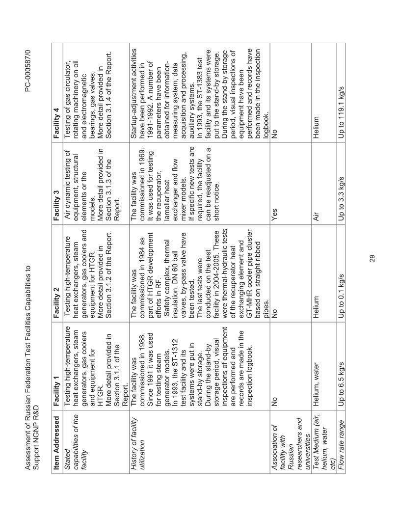
The facility is currently in storage. Actions required to enable the use of the facility will be replacing controls and monitoring systems, as well as information-measurement systems. In addition, assessment of the remaining equipment must be performed, and some equipment will have to be replaced as needed. Startup adjustment of the resulting modified facility, including equipment tune-up, must be conducted prior to testing. Detailed specifications for each individual test program proposed at the facility will be required to estimate the cost and the time needed for appropriate adjustments and modifications. OKBM stated that once this test facility was put into operation in 1991, the first stage of startup-adjustment activities was performed, thus enabling the main and auxiliary circuits, the circulator, and other systems. The gas circulator was brought to a speed of 600 rpm, which is only 10% of its nominal design speed. In 1992, this facility was put into storage mode. A physical inspection of Test Facility ST-1383 by the U.S. team was conducted on 11/27/09. Although this is a very large facility with useful hardware, its application to NGNP technology development does not appear feasible. The facility has been shut down since 2001. The circulator was never rotated to full speed as initially intended because the facility was abandoned. Information measuring, control, and data storage systems are out of date, so they would require a complete upgrade. GA does not consider potential application of this facility to NGNP technology development to be practical. 3.1.5. Summary Table of OKBM Test Loops This section briefly summarizes capabilities, history and several other specific technical points relevant to the test facilities described above. As such, Table 3-1 below is complementary to the descriptions provided earlier in this section.

Ass
essm
ent o
f Rus
sian
Fed
erat
ion
Test
Fac
ilitie
s C
apab
ilitie
s to
S
uppo
rt N
GN
P R
&D
P
C-0
0058
7/0
28
Tabl
e 3-
1. S
umm
ary
of O
KB
M H
eliu
m a
nd A
ir Te
st L
oops
Ite
m A
ddre
ssed
Fa
cilit
y 1
Faci
lity
2 Fa
cilit
y 3
Faci
lity
4 Fa
cilit
y na
me
and
Bui
ldin
g N
umbe
r
Test
Fac
ility
for S
team
G
ener
ator
Mod
el a
nd
Hig
h-Te
mpe
ratu
re H
eat
Exc
hang
ers
ST-
1312
, Bui
ldin
g 52
Mul
tipur
pose
Res
earc
h C
ompl
ex
ST-
1565
, Bui
ldin
g 04
Air
test
Fac
ility
B
uild
ing
09
Mai
n C
ircul
ator
Tes
t Fac
ility
S
T-13
83, B
uild
ing
52
Loca
tion
OK
BM
terr
itory
O
KB
M te
rrito
ry
OK
BM
terr
itory
O
KB
M te
rrito
ry
Des
crip
tion
of th
e te
st fa
cilit
y an
d te
st c
ell
The
faci
lity
is d
esig
ned
to te
st th
e la
rge-
scal
e st
eam
gen
erat
or m
odel
an
d hi
gh-te
mpe
ratu
re
heat
exc
hang
ers
unde
r co
nditi
ons
corr
espo
ndin
g to
HTG
R p
aram
eter
s.
Faci
lity
enab
les
inve
stig
atio
n of
hyd
raul
ic
and
vibr
atio
n pe
rform
ance
of s
team
ge
nera
tors
and
hea
t ex
chan
gers
as
wel
l as
the
ther
mal
con
ditio
ns o
f st
ruct
ural
mat
eria
ls.
Mor
e de
tail
prov
ided
in
Sec
tion
3.1.
1 of
the
Rep
ort.
Mul
tipur
pose
faci
lity
for
test
ing
mod
els
of h
eat
exch
ange
r and
oth
er
equi
pmen
t for
HTG
R p
lant
s.
The
faci
lity
enab
les
inve
stig
atio
n of
ther
mal
-hy
drau
lic p
erfo
rman
ce o
f st
eam
gen
erat
ors
and
heat
ex
chan
ge m
odul
es.
The
faci
lity
also
pro
vide
s ca
pabi
lity
of te
stin
g l
oss
of
pres
sure
in th
e pr
imar
y ci
rcui
t and
wat
er in
gres
s in
th
e pr
imar
y ci
rcui
t. M
ore
deta
il pr
ovid
ed in
S
ectio
n 3.
1.2
of th
e R
epor
t.
The
faci
lity
enab
les
inve
stig
atio
n of
hy
drau
lic p
erfo
rman
ce
of re
acto
r stru
ctur
al
elem
ents
and
oth
er
equi
pmen
t, ve
rific
atio
n of
com
pute
r cod
es.
The
addi
tiona
l ca
pabi
lity
is a
ir dy
nam
ic te
stin
g of
eq
uipm
ent,
incl
udin
g hy
drau
lic re
sist
ance
. M
ore
deta
il pr
ovid
ed in
S
ectio
n 3.
1.3
of th
e R
epor
t.
The
faci
lity
is d
esig
ned
to
test
a p
ilot s
ampl
e of
the
mai
n ci
rcul
ator
for H
TGR
pl
ant.
Mor
e de
tail
prov
ided
in
Sec
tion
3.1.
4 of
the
Rep
ort.
Ass
essm
ent o
f Rus
sian
Fed
erat
ion
Test
Fac
ilitie
s C
apab
ilitie
s to
S
uppo
rt N
GN
P R
&D
P
C-0
0058
7/0
29
Item
Add
ress
ed
Faci
lity
1 Fa
cilit
y 2
Faci
lity
3 Fa
cilit
y 4
Sta
ted
capa
bilit
ies
of th
e fa
cilit
y
Test
ing
high
-tem
pera
ture
he
at e
xcha
nger
s, s
team
ge
nera
tors
, gas
coo
lers
an
d eq
uipm
ent f
or
HTG
R.
Mor
e de
tail
prov
ided
in
Sec
tion
3.1.
1 of
the
Rep
ort.
Tes
ting
high
-tem
pera
ture
he
at e
xcha
nger
s, s
team
ge
nera
tors
, gas
coo
lers
and
eq
uipm
ent f
or H
TGR
. M
ore
deta
il pr
ovid
ed in
S
ectio
n 3.
1.2
of th
e R
epor
t.
Air
dyna
mic
test
ing
of
equi
pmen
t, st
ruct
ural
el
emen
ts o
r the
m
odel
s.
Mor
e de
tail
prov
ided
in
Sec
tion
3.1.
3 of
the
Rep
ort.
Test
ing
of g
as c
ircul
ator
, ro
tatin
g m
achi
nery
on
oil
and
elec
trom
agne
tic
bear
ings
, gas
val
ves.
M
ore
deta
il pr
ovid
ed in
S
ectio
n 3.
1.4
of th
e R
epor
t.
His
tory
of f
acili
ty
utili
zatio
n Th
e fa
cilit
y w
as
com
mis
sion
ed in
198
8.
Sin
ce 1
991
it w
as u
sed
for t
estin
g st
eam
ge
nera
tor m
odel
s.
In 1
993,
the
ST-
1312
te
st fa
cilit
y an
d its
sy
stem
s w
ere
put i
n st
and-
by s
tora
ge.
Dur
ing
the
stan
d-by
st
orag
e pe
riod,
vis
ual
insp
ectio
ns o
f equ
ipm
ent
are
perfo
rmed
and
re
cord
s ar
e m
ade
in th
e in
spec
tion
logb
ook.
The
faci
lity
was
co
mm
issi
oned
in 1
984
as
part
of H
TGR
dev
elop
men
t ef
forts
in R
F.
Saf
ety
com
plex
, the
rmal
in
sula
tion,
DN
60
ball
valv
es, b
y-pa
ss v
alve
hav
e be
en te
sted
. Th
e la
st te
sts
wer
e co
nduc
ted
on th
e te
st
faci
lity
in 2
004-
2005
. The
se
wer
e th
erm
al-h
ydra
ulic
test
s of
the
recu
pera
tor h
eat
exch
angi
ng e
lem
ent a
nd
GT-
MH
R c
oole
r pip
e cl
uste
r ba
sed
on s
traig
ht ri
bbed
pi
pes.
The
faci
lity
was
co
mm
issi
oned
in 1
969.
It
was
use
d fo
r tes
ting
the
recu
pera
tor,
lam
ella
r hea
t ex
chan
ger a
nd fl
ow
mix
er m
odel
s.
If sp
ecifi
c ne
w te
sts
are
requ
ired,
the
faci
lity
can
be re
adju
sted
on
a sh
ort n
otic
e.
Sta
rtup-
adju
stm
ent a
ctiv
ities
ha
ve b
een
perfo
rmed
in
1991
-199
2. A
num
ber o
f pa
ram
eter
s ha
ve b
een
obta
ined
for i
nfor
mat
ion-
mea
surin
g sy
stem
, dat
a ac
quis
ition
and
pro
cess
ing,
au
xilia
ry s
yste
ms.
In
199
3, th
e S
T-13
83 te
st
faci
lity
and
its s
yste
ms
wer
e pu
t to
the
stan
d-by
sto
rage
. D
urin
g th
e st
and-
by s
tora
ge
perio
d, v
isua
l ins
pect
ions
of
equi
pmen
t hav
e be
en
perfo
rmed
and
reco
rds
have
be
en m
ade
in th
e in
spec
tion
logb
ook.
A
ssoc
iatio
n of
fa
cilit
y w
ith
Rus
sian
rese
arch
ers
and
univ
ersi
ties
No
No
Yes
N
o
Test
Med
ium
(air,
he
lium
, wat
er
etc)
Hel
ium
, wat
er
Hel
ium
A
ir H
eliu
m
Flow
rate
rang
e U
p to
6.5
kg/
s U
p to
0.1
kg/
s U
p to
3.3
kg/
s U
p to
119
.1 k
g/s

Ass
essm
ent o
f Rus
sian
Fed
erat
ion
Test
Fac
ilitie
s C
apab
ilitie
s to
S
uppo
rt N
GN
P R
&D
P
C-0
0058
7/0
30
Item
Add
ress
ed
Faci
lity
1 Fa
cilit
y 2
Faci
lity
3 Fa
cilit
y 4
Pre
ssur
e ra
nge
Up
to 5
MP
a U
p to
5 M
Pa
1 ba
r U
p to
4.9
MP
a Te
mpe
ratu
re
rang
eFr
om 3
50 to
965�C
U
p to
965�C
U
p to
360�C
U
p to
400�C
Hea
ting
capa
city
U
p to
15
MW
U
p to
250
kW
U
p to
100
kW
N
/A
Coo
ling
capa
city
(fa
cilit
y he
at
reje
ctio
nca
pabi
lity
– e.
g.
cool
ing
tow
er
capa
city
)
Up
to 5
MW
U
p to
250
kW
U
p to
100
kW
1.
01 M
W
Siz
e of
test
cel
l 24
.6 m
× 1
6.8
m ×
17.
1 m
10
m ×
10
m ×
6 m
15
m ×
4 m
× 4
m
The
verti
cal g
ap p
rovi
ding
an
acc
ess
to th
e ro
om
bene
ath
the
pede
stal
–
4500
×900
0 m
m
Des
crip
tion
of
mat
eria
ls in
test
ce
ll
Rei
nfor
ced
conc
rete
S
teel
-
Rei
nfor
ced
conc
rete
Max
imum
siz
e of
te
st a
rticl
e th
at
coul
d be
pla
ced
in fa
cilit
y
Mod
el d
iam
eter
~ 1
-1.5
m
M
odel
hei
ght ~
10
m
(ver
tical
pos
ition
ing)
Mod
el d
iam
eter
~ 0
.5 m
H
eigh
t ~
3 m
(ver
tical
po
sitio
ning
) C
onne
ctio
n di
men
sion
s ar
e D
N 6
5 m
m –
by
wel
ding
.
The
mod
el d
imen
sion
s ar
e lim
ited
by c
ircul
ator
ca
paci
ty.
Dia
met
er –
up
to 4
000
mm
. H
eigh
t – u
p to
800
0 m
m.
Wei
ght –
up
to 6
0000
kg.
Cra
ne c
apac
ity /
head
room
10
0/20
t 50
/10
t H
ook
heig
ht –
30
m
15 t
Hoo
k he
ight
– 1
2 m
5
t 10
0/20
t 50
/10
t H
ook
heig
ht –
30
m
Circ
ulat
or p
ower
40
0 kW
30
kW
50
kW
6.
3 M
W
Tota
l ele
ctric
al
pow
er a
vaila
ble
at fa
cilit
y
17 M
W
300
kW
100
kW
6.5
MW

Ass
essm
ent o
f Rus
sian
Fed
erat
ion
Test
Fac
ilitie
s C
apab
ilitie
s to
S
uppo
rt N
GN
P R
&D
P
C-0
0058
7/0
31
Item
Add
ress
ed
Faci
lity
1 Fa
cilit
y 2
Faci
lity
3 Fa
cilit
y 4
Ava
ilabl
e ut
ilitie
s (p
lant
air,
in
stru
men
t air,
se
rvic
e w
ater
, de
min
. wat
er,
othe
r)
The
faci
lity
inco
rpor
ates
a
heliu
m lo
op, d
istil
led
wat
er lo
op, r
ecyc
labl
e w
ater
loop
The
faci
lity
inco
rpor
ates
a
heliu
m lo
op, a
ir lo
op,
dist
illed
wat
er lo
op a
nd
recy
clab
le w
ater
loop
The
faci
lity
inco
rpor
ates
two
air
loop
s.
The
faci
lity
inco
rpor
ates
a
heliu
m lo
op a
nd re
cycl
able
w
ater
loop
, vac
uum
and
ve
ntila
tion
syst
ems.
Con
trol S
yste
m
(dis
tribu
ted,
anal
og, d
ate
of
last
maj
or
upgr
ade)
Ana
log
Ana
log
1987
TB
D
Ana
log
Dat
a A
cqui
sitio
n sy
stem
(dat
e of
la
st u
pgra
de)
Upg
rade
requ
ired
Upg
rade
requ
ired
TBD
U
pgra
de re
quire
d
Cur
rent
Sta
tus
In s
tora
ge
Rea
dy fo
r tes
ts a
fter
upgr
ades
In
regu
lar u
se
In s
tora
ge
Ava
ilabi
lity
of
expe
rienc
ed
pers
onne
l to
staf
f th
e fa
cilit
y
Yes
Y
es
Yes
Y
es
Ser
ious
acci
dent
s in
volv
ing
pers
onne
l inj
ury
or d
eath
?
No
No
No
No
Tim
e re
quire
d to
ge
t the
faci
lity
read
y fo
r tes
ting
2.5
– 3
yea
rs
2.5
– 3
year
s
TBD
TB
D
Cos
t for
re
furb
ishi
ng~
$28
Mill
ion
~$7.
1 M
illio
n TB
D
TBD

Assessment of Russian Federation Test Facilities Capabilities to Support NGNP R&D
PC-000587/0
32
3.2. Test Facilities at NIIAR, RRC-KI and NPO Lutch to Support NGNP Technology Development
In addition to the evaluation of the RF non-nuclear test facilities, this effort was expanded to include evaluation of some of the nuclear-related capabilities in RF. These capabilities include research reactors, test loops similar to those in the INL’s Advanced Test Reactor, and post irradiation examination facilities and are discussed in the following sections. 3.2.1. PG-1 Test Loop at NIIAR In-pile tests at the PG-1 circuit are relevant to several areas of fission product transport (FPT) technology development. In particular, tests at the PG-1 loop may be considered for the following areas associated with the NGNP Program – fission gas and fission metal release data validation, validation of plateout distributions, and validation of radionuclide (RN) ‘liftoff’ and ‘washoff’ data. The PG-1 circuit (Figure 3-17) is a part of the ‘MIR’ research reactor located at NIIAR. The PG-1 circuit has been designed to study transport of fission products in N2 coolant (Ref. 4).
1 – Loop channel; 2 – Safety shells; 3 – Protection shield; 4 – Recuperator; 5 – Condenser; 6 – Gas circulator; 7 – Hydraulic accumulator of the emergency heat removal system; 8 – Equipment cooling system A; 9 – Equipment cooling system B; 10 – System of emergency heat removal from the channel; 11 – Mixer; 12 – Throttle; 13 – Pressure compensator; 14 – Heat exchanger; 15 – Bypass line.
Figure 3-17. Diagram of the PG-1 loop facility

Assessment of Russian Federation Test Facilities Capabilities to Support NGNP R&D
PC-000587/0
33
The key operating parameters of the PG-1 test loop are given in Table 3-2.
Table 3-2. Technical Parameters of the PG-1 Loop Parameter Unit Value Maximum loop consumption power kW 120 Pressure MPa Up to 20
Coolant - N2 – potential use of other noble gases is possible
Gas flow rate, if one circulator is in operation m3/h Up to 19 Compression ratio of the circulators - 1.06 Maximum permissible specific gas activity Bq/l Up to 3.7�1010 This circuit was operated in combination with the loop channel of the reactor ‘Mir’, the operating parameters of which are given in Table 3-3.
Table 3-3. Parameters of the loop channel in PG-1 circuit of 'MIR' reactor
Parameter Unit Value Channel diameter mm From 90 to 148 Core height mm 1000 Maximum flux of thermal neutrons in the channel cm-2�s-1 Up to 5.1014 Maximum flux of fast neutrons with �>0.18 MeV in the channel cm-2�s-1 Up to 0.3�1014
Maximum gas temperature in the channel °� Up to 900 Maximum gas temperature at the outlet of the loop channel °� Up to 550
Total channel operation time hour 600 3.2.2. NIIAR Test Facilities for Fuel Irradiation Fuel irradiation and FPT tests of UCO fuel particles can be performed at the SM-3 and RBT-6 research reactors at NIIAR. Table 3-4 provides some key characteristics of these research reactors.

Assessment of Russian Federation Test Facilities Capabilities to Support NGNP R&D
PC-000587/0
34
Table 3-4. Characteristics of NIIAR Research Reactors
Value SM-3 RBT-6 Parameter Cell 5 Cell D2 Cell 10 Cell 1-8
Core height, mm 350 350 350 350 Diameter of experimental channel, mm 64 64 64 64 Number of similar cells, pcs 4 4 4 8 Density of thermal neutron flux, �1014 n�cm-2�s-1 3.2 3.9 2.6 0.5
Density of fast neutron flux (E>0.18MeV), �1014 n�cm-2�s-1 4.1 1.8 0.74 0.52
Neutron fraction with energy more than: 0.18 MeV 1 keV 2 eV
0.29 0.54 0.75
0.18 0.38 0.59
0.14 0.32 0.53
0.31 0.5 0.66
The SM-3 reactor is a closed 90-MW pressure vessel reactor and is cooled with light water. Water temperature at the reactor inlet is 50°�, and up to 95°� at the reactor outlet. The coolant pressure is 5 MPa. Figure 3-18 shows a horizontal cross-section of the reactor. The core consists of 28 square (69 x 69 mm) Fuel Assemblies (FA). The core is surrounded by a beryllium, water cooled side reflector. There are 30 channels with the inner diameter of 64 mm arranged in the beryllium reflector at various distances from the side of the core. These channels are for irradiation of the fuel, absorber, and structural and other materials. Materials can also be irradiated in the core at a fast neutron flux of 1.8×10¹⁵ n�cm-2�s-1 (� > 0.18 MeV) in a position having a diameter of 12.5 mm. The RBT-6 reactor is an open-pool type reactor having a thermal power of 6 MW and a core utilizing spent FAs from the SM-3 reactor. Core height is 350 mm. Figure 3-19 shows the core horizontal cross-section. Eight experimental channels are arranged in the core cells; the core grid allows arranging channels in place of any of the FA. Experimental devices are cooled by primary pool cooling circuit. Neutronic characteristics of all the channels are similar (see Table 3-4). Density of the fast neutron flux is 3.4 - 5.6 ×10¹³ n�cm-2�s-1 (�> 0.18 MeV), and the specific power from gamma radiation is 1.1 - 2.0 W/g.

Assessment of Russian Federation Test Facilities Capabilities to Support NGNP R&D
PC-000587/0
35
Figure 3-18. Horizontal Cross-Section of SM-3 Research Reactor

Assessment of Russian Federation Test Facilities Capabilities to Support NGNP R&D
PC-000587/0
36
Figure 3-19. Cross-Section View of RBT-6 Reactor Core
There are currently three designs of irradiation devices (IDs) for both the SM-3 and RBT-6 reactors (Ref. 5). The IDs enable carrier gas sampling from the area around the fuel to determine radionuclide contents and/or investigate the chemical composition. The gamma-spectral analysis results enable the determination of the R/B ratio for noble gases. The design of the IDs also allows for measurement and control of fuel temperature in each ID. The design of ID-1 is intended for selection of the fuel design, matrix composition, and technology. ID-2 is to be used for demonstration of the best-selected fuel design and technology. Finally, ID-3 is intended for ‘express’ tests of individual CFP process options or special samples. Schematic diagrams of the three irradiation devices are shown in Figure 3-20.

Assessment of Russian Federation Test Facilities Capabilities to Support NGNP R&D
PC-000587/0
37
Figure 3-20. Diagrams of Irradiation Devices at NIIAR A schematic diagram showing integration of these IDs into the SM-3 and RBT-6 gas sampling test facility is shown in Figure 3-21.

Assessment of Russian Federation Test Facilities Capabilities to Support NGNP R&D
PC-000587/0
38
Figure 3-21. NIIAR Irradiation Gas Sampling Test Facility Diagram Both the SM-3 and RBT-6 research reactors are being upgraded under the work on investigation of fuel performance within the GT-MHR program. Following the upgrade, it will become possible to perform a variety of studies on the fuel element materials for high-temperature gas reactors. 3.2.3. Post-Irradiation Test Complex at NIIAR The post-irradiation test facility at NIIAR is used for examination of the samples from the irradiated capsules for their composition, micro- and macrostructure, and mechanical and physical properties. The properties of structural, moderating, and absorbing materials can also be investigated. There is significant experience at this facility related to examinations of a broad variety of irradiated reactor fuel samples, including HTGR spherical fuel elements. The currently-planned examination sequence for coated fuel particles at the post-irradiation complex assumes a visual inspection of selected coated particles, particle metallography, and determination of fission product release kinetics. Mass spectrometry is used to determine the
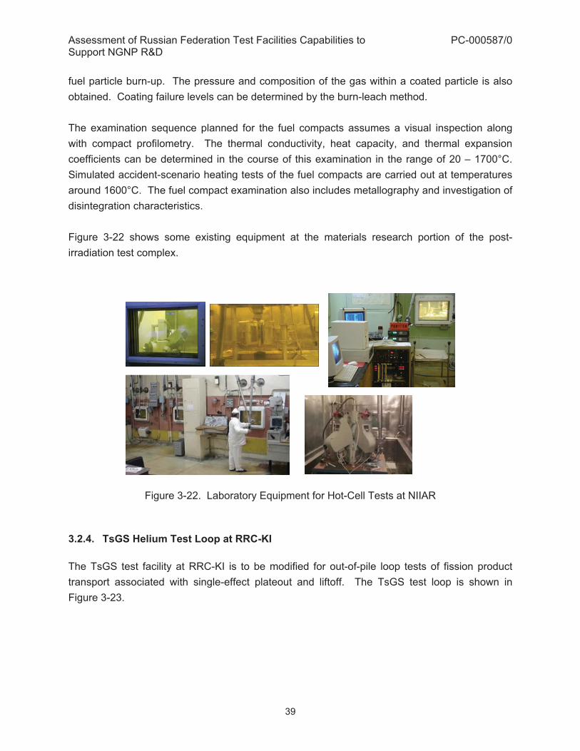
Assessment of Russian Federation Test Facilities Capabilities to Support NGNP R&D
PC-000587/0
39
fuel particle burn-up. The pressure and composition of the gas within a coated particle is also obtained. Coating failure levels can be determined by the burn-leach method. The examination sequence planned for the fuel compacts assumes a visual inspection along with compact profilometry. The thermal conductivity, heat capacity, and thermal expansion coefficients can be determined in the course of this examination in the range of 20 – 1700°C. Simulated accident-scenario heating tests of the fuel compacts are carried out at temperatures around 1600°C. The fuel compact examination also includes metallography and investigation of disintegration characteristics. Figure 3-22 shows some existing equipment at the materials research portion of the post-irradiation test complex.
Figure 3-22. Laboratory Equipment for Hot-Cell Tests at NIIAR 3.2.4. TsGS Helium Test Loop at RRC-KI The TsGS test facility at RRC-KI is to be modified for out-of-pile loop tests of fission product transport associated with single-effect plateout and liftoff. The TsGS test loop is shown in Figure 3-23.

Assessment of Russian Federation Test Facilities Capabilities to Support NGNP R&D
PC-000587/0
40
Figure 3-23. TsGS Test Loop at RRC-KI The key technical parameters of the upgraded TsGS test loop are provided in Table 3-5.

Assessment of Russian Federation Test Facilities Capabilities to Support NGNP R&D
PC-000587/0
41
Table 3-5. Main Technical Characteristics of Upgraded TsGS Test Facility
Title Value Gas circuit characteristics Working pressure range 1.5 – 10 atm Working temperature range 50 – 900�� Circuit volume 0.9 m3 Safety valve trip limit 12.5 atm Gas circulator characteristics Gas circulator head coefficient 1.03 Helium heating into compressor to 80�C Motor speed 2950 rpm Maximum helium flow rate at P = 10 atm 0.01 kg/s Helium volume flow rate at t = 50 �C and P = 10 atm 0.065 m3/s Heater characteristics Power supply voltage (controlled) 0 – 210 V Helium temperature at heater outlet to 900�C Cooler characteristics Gas temperature at cooler inlet to 800�C Gas temperature downstream the first part of cooler 300�C Gas temperature downstream cooler 50�C Gas temperature downstream cooler 50�C
The electric power available at the facility is 75 kW. A schematic diagram of the TsGS test loop is shown in Figure 3-24.

Assessment of Russian Federation Test Facilities Capabilities to Support NGNP R&D
PC-000587/0
42
�, t –pressure and temperature measurements 1 – gas circulator 15 – vacuum valve (VV) 2 – helium purification system 16 – gas filtration system in gas circulator
casing 3 – CV (flowrate control valve) 17 – circuit degassing system 4 – flow meter for main flow 18 – HV (filling system valve) 5 – 4-section heater 19 – helium cylinders 6 – temperature-controlled chamber with ampoule containing radioactive source
20 – into special ventilation
7 – radioactive source valve 21 – to source control system 8 – sector of mixing of main flow with helium flow from source 22 – cooler water cooling system 9 – working sector 23 – 31 – isolation valve 10 – preliminary filter 34 – 37 – discharge to aerosol control in
circuit 11 – moving gamma-detector 32 –aerosol particle generator 12 – two-section cooler 38 – helium flow meter in source system 13 – absolute filter 39 – helium flow meter in aerosol
preparation system 14 – BV (bypass valve) 40 – aerosol filter
Figure 3-24. Schematic Diagram of TsGS Test Loop

Assessment of Russian Federation Test Facilities Capabilities to Support NGNP R&D
PC-000587/0
43
The TsGS test loop shown in Figure 3-24 is to be upgraded for conducting further experiments under the GT-MHR Program. The upgraded facility can be useful for NGNP technology development as well. In particular, the water injection input system could be particularly useful in meeting NGNP technology development needs. The following changes are expected to be implemented with respect to the flow sheet and the arrangement of equipment:
� Length reduction of the working sector (9) to 1.5 m so that there is a shorter connection between the mixer (8) and the high-temperature filter (10)
� Insertion of the absolute radioactivity filter (13) downstream the cooler � Connection of the RN water injection input system to the mixer (8). The water injection
system comprises the chamber with radioactive source (6), helium cylinders (19), the source control system (21), valves (7) and (24)
� Arrangement for the trolley with the gamma-detector (11) to move along the working sector on guide rails
� Arrangement for the additional sensors for the coolant pressure, flow rate and temperature.
The TsGS test facility at RRC-KI is not currently in operation, but its modification is planned to enable the use of this facility for out-of-pile loop tests of fission product transport. 3.2.5. ASTRA Critical Test Facility at RRC-KI The critical test facility began operation in 1980 at RRC-KI. It is designed for experimental studies of neutronic characteristics of high temperature helium reactors (Ref. 6). Recently, critical assemblies simulating physical features of reactors with annular cores (PBMR and GT-MHR) were studied experimentally. The program of experimental studies at ASTRA includes:
� Critical parameters of the core under various configurations � Worth of control rods located in the core and in the reflector � Spatial distribution measurements of fission reaction rates � Study and measurement of different zoning schemes for fuel and burnable poison � Measurement of the reactivity effects of various materials
A general view and cross-section of the ASTRA critical test facility are shown in Figure 3-25. The load-bearing structure is a steel casing with a bottom installed on a rigid basement. The

Assessment of Russian Federation Test Facilities Capabilities to Support NGNP R&D
PC-000587/0
44
inner diameter of casing is 3800 mm, the thickness of the side wall is 110 mm, and the bottom thickness is 20 mm. For annular core configurations (shown in Figure 3-25), the side reflector consists of an outer diameter of 380 cm and a height of 460 cm with the lower reflector installed on the bottom casing. The annular cavity arrangement is filled with spherical fuel elements. The void space (free of assembly elements, cavities, channels, etc.) is filled with air under normal conditions.
Figure 3-25. Critical Assembly with Annular Core Simulating GT-MHR Physical Features
The main technical characteristics of the ASTRA critical test facility are provided in Table 3-6.

Assessment of Russian Federation Test Facilities Capabilities to Support NGNP R&D
PC-000587/0
45
Table 3-6. Main Technical Characteristics of ASTRA Critical Facility Main components and parameters
ASTRA critical test facility
Core Annular Core height-to-thickness ratio Hcore/Tcore
8.7
Core height-to-diameter ratio Hcore/Dcore.
1.8
Core thickness-to- diameter ratio Tcore/Dcore
0.22
CR diameter-to-core diameter ratio dcm/Dcore
0.04
Core moderator Graphite Reflector moderator (SR, UR, LER, UER)
Graphite
Control rod absorber material Natural boron carbide Control rod arrangement Side reflector, core and inner reflector Fuel Uranium oxide, enrichment
20%, Pu oxide without diluent
Coated fuel particle Kernel of diameter 500 μm Kernel of diameter 200 μm
Nc/Nf (*) in the core 7800 3600 - 7800 Core structure Sphere fuel elements Prismatic fuel elements Fuel element type Sphere fuel elements with coated
fuel particles Compacts with coated fuel particles
Fuel particle coating TRISO Fuel element matrix Graphite (*)Note: Nc/Nf = ratio of the number of carbon atoms to the average number of fissionable atoms in the core. The work involving plutonium oxide at the ASTRA facility is planned for future experiments. The ASTRA critical test facility is currently in operation, and it is being upgraded for critical experiments at higher temperatures (600°C). The objectives of the hot critical experiments are to:
� Obtain the temperature reactivity effect and its constituents � Determine the critical position of the control rods � Obtain the worth of the individual control rods

Assessment of Russian Federation Test Facilities Capabilities to Support NGNP R&D
PC-000587/0
46
� Determine the control bank worth and shutdown reactivity margin The test facility cross section for hot critical experiments is shown in Figure 3-26.
Figure 3-26. Cross Section of ASTRA Facility Set Up for Hot Critical Experiments
3.2.6. Sorption and Diffusion Test Facility at NPO Lutch The sorption and diffusion test facility at NPO Lutch (shown in Figure 3-27) is used for studies of silver and cesium sorption and diffusion on structural material samples. In particular, the facility has been used for assessment of characteristic times of reaching maximum allowed silver and cesium composition (1 mkg/cm2) on turbine blades in the GT-MHR program. This test facility has also been used to determine the required clear-out surface thickness of samples for radiation safety. The pressure ranges for silver and cesium were specifically selected to enable study of the sorption of Ag and Cs because the pressures of residual oxygen and oxygen containing impurities are smaller by orders of magnitude than Ag and Cs. Thus, oxides of Ag and Cs are not present in the gas phase and the sorption process can be studied with greater accuracy. Tests are conducted in a wide range of temperatures and pressures of the Ag and Cs vapors. Ag vapors are generated by controlled heating of a Knudsen cell located in an
IC – ionization chambers; NM – neutron counters. Dark areas in the side reflector correspond to graphite blocks with plugs, the other blocks have central holes.

Assessment of Russian Federation Test Facilities Capabilities to Support NGNP R&D
PC-000587/0
47
isothermal region of the vacuum chamber, while Cs vapors are supplied through a heated vapor line equipped with a pressure gauge. To study Ag and Cs diffusion and sorption, sample surface morphology investigation is conducted before and after tests. These studies involve the methods of X-ray photoelectron spectroscopy and Auger electron spectroscopy for sample analysis layer by layer, removing the layers by ion treatment.
Figure 3-27. Experimental Setup at NPO Lutch for Sorption and Diffusion Process Studies The test facility includes a vacuum cell for the experiments, evacuation system, Ag and Cs vapor generation system, sample heating devices, supply piping system, temperature and pressure measurement system, argon supply system, and computer registration system for

Assessment of Russian Federation Test Facilities Capabilities to Support NGNP R&D
PC-000587/0
48
temperatures and pressures. Specific technical characteristics of this test facility are given in Table 3-7.
Table 3-7. Technical Characteristics of NPO Lutch Sorption and Diffusion Test Facility Working temperature range for tested samples
400 – 900 �C
Pressure range for silver vapors (1.3x10⁻⁶ - 1.3x10⁻⁴) atm Pressure range for cesium vapors (1.3x10⁻⁶ - 1.3x10⁻⁴) atm Duration of continuous operation At least 100 hours Pressure of residual gases in the vacuum chamber
6.6x10⁻⁸ atm
Required power 4 kW Voltage of supplied electricity 220/380 V Electricity frequency 50 Hz Area occupied by equipment (2.5 x 1.5) m Weight of equipment 200 kg
Installation and adjustment of the sorption and diffusion test facility has been done. Test samples of turbine blade alloys have been manufactured for studying Ag and Cs diffusion and sorption. 3.2.7. ‘PARAMETER’ Test Facility at NPO Lutch
The ‘PARAMETER’ test facility at NPO Lutch can be used to conduct studies on the corrosion behavior of fuel compacts for HTGR reactors. Figure 3-28 shows the control room for this test facility.
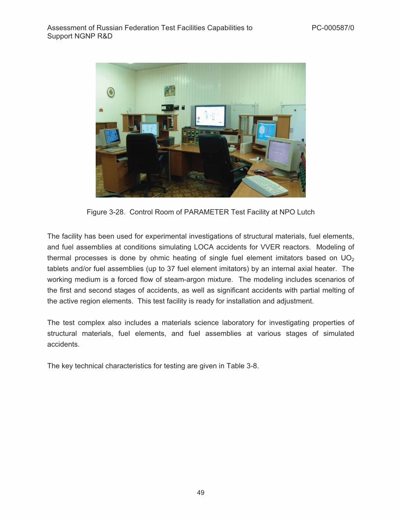
Assessment of Russian Federation Test Facilities Capabilities to Support NGNP R&D
PC-000587/0
49
Figure 3-28. Control Room of PARAMETER Test Facility at NPO Lutch
The facility has been used for experimental investigations of structural materials, fuel elements, and fuel assemblies at conditions simulating LOCA accidents for VVER reactors. Modeling of thermal processes is done by ohmic heating of single fuel element imitators based on UO2 tablets and/or fuel assemblies (up to 37 fuel element imitators) by an internal axial heater. The working medium is a forced flow of steam-argon mixture. The modeling includes scenarios of the first and second stages of accidents, as well as significant accidents with partial melting of the active region elements. This test facility is ready for installation and adjustment. The test complex also includes a materials science laboratory for investigating properties of structural materials, fuel elements, and fuel assemblies at various stages of simulated accidents. The key technical characteristics for testing are given in Table 3-8.

Assessment of Russian Federation Test Facilities Capabilities to Support NGNP R&D
PC-000587/0
50
Table 3-8. Technical Characteristics of NPO Lutch PARAMETER Test Facility
Heat transfer fluid Superheated steam/argon Flow rate of heat transfer fluid 0.2 / 0.1 g/s per fuel element Heat transfer fluid temperature at the inlet of fuel assembly model
500 �C
Rate of heating of fuel element surface 0.5 to 4 �C /s for assemblies and up to 80 �C /s for single element imitators
Maximum temperature of fuel element surface 800 – 2000 �C Water consumption rate (feed from the top) Up to 2 g/s per fuel element Water consumption rate (feed from the bottom)
Up to 5 g/s per fuel element
Assessment of Russian Federation Test Facilities Capabilities to Support NGNP R&D
PC-000587/0
51
4. ASSESSMENT OF RF TEST FACILITIES TO SATISFY NGNP DDNS
An assessment of the potential use of the RF facilities to satisfy NGNP DDNs and associated NGNP technology development plans for both 750°C (and 950°C) outlet temperatures is included in this section. Section 5 identifies specific NGNP test programs that could potentially be conducted in RF facilities. For the purpose of this assessment, the NGNP DDNs summarized in Table 3-1 in GA report PC-000570 (Ref. 7) were utilized. The specific DDNs which are considered relevant to the component test facilities at OKBM described in Section 3.1 are listed in Table 4-1. Where applicable, the corresponding NGNP SSCs are also identified in Table 4-1. The table also identifies the tests that are considered relevant to the proposed INL CTC. Post Irradiation Examination (PIE) and Post Irradiation Heating (PIH) facilities for coated particle fuel are planned at NIIAR as part of the RF GT-MHR fuel development program. Lab sorption and Lab permeation measurement facilities are planned as part of the RF GT-MHR program at RRC-KI and NPO Lutch. Table 4-1 has been modified to include additional DDNs for completeness. Table 4-2 presents a list of DDNs in the areas of fuel performance, fission product transport, reactor and vessel system, shutdown cooling system, and Plant Control Data and Instrumentation System (PCD&IS) which could be addressed by the other RF testing facilities discussed in Section 3.2. In addition to the RF facilities described in Section 3 above, OKBM’s Electro Magnetic Bearings Testing Facility (ETF) and Seal Testing Facility (STF), which are currently in use for the GT-MHR Program, are also mentioned in Table 4-1.

Assessment of Russian Federation Test Facilities Capabilities to Support NGNP R&D
PC-000587/0
52
Table 4-1. NGNP Design Data Needs Relevant to Capabilities of OKBM Facilities NGNP SSC #
DDN No. DDN Title Facility Relevance to CTC
Applicable NGNP Temp. Range 1, 2, 31
C.11.00 REACTOR System (RS) C.11.01 Neutron Control System C.11.01.01 Control Rod Instrumentation and
Control Verification Air Test Facility
C.11.01.02 Qualification of Electromechanical Components of Neutron Control Assembly
Air Test Facility
C.11.01.03 Control Rod Drive Design Verification
Air Test Facility
C.11.01.04 Reserve Shutdown Control Equipment Design Verification
Air Test Facility
C.11.01.05 In-Core Flux Mapping Unit (IFMU) Drive Design Verification
Air Test Facility
C.11.01.07 Neutron Control Assembly Flow and Leak Design Verification
Air Test Facility
C.11.01.08 Guide Tubes Flow Induced Vibration Design Verification
ST-1312 YES 2
C.11.01.09 Demonstration of Remote Handling and Maintenance of Neutron Control Assembly
Air Test Facility
C.11.01.11 Neutron Control Assembly Qualification Test
Air Test Facility
N.11.01.14 Control Rod (CR) & Reactor Shut down System Material (RSSM) Guide Tubes - Effects on Composites of Primary He and Temperature
ST-1312, ST-1565
C.11.02 Reactor Internals (RI) and Hot Duct C.11.02.02
B.13.03.25 Hot Duct Integrity Verification Air Test
Facility, ST-1312 & ST-1565
2
N.11.02.10 Effects of Primary He and Temperature on Metallic Reactor Internals Materials
ST-1312 & ST-1565
YES 2
3 N.11.02.13 C.11.02.13 B.13.03.28
Effects of Primary He and Temperature on Hot Duct Materials
Air Test Facility, ST-1312 & ST-1565
YES 2
3 C.11.02.14 B13.03.29
Fibrous Insulation Material Properties
Air Test Facility, ST-1312 & ST-1565
YES 2
1 1 –Testing at 750°C Max.; 2 – Testing at 750°C or 950°C; 3 – Testing at 950°C

Assessment of Russian Federation Test Facilities Capabilities to Support NGNP R&D
PC-000587/0
53
NGNP SSC #
DDN No. DDN Title Facility Relevance to CTC
Applicable NGNP Temp. Range 1, 2, 31
3 C.11.02.15 Hard Ceramic Insulation Properties Data
Air Test Facility, ST-1312 & ST-1565
YES 2
N.11.02.19 Hot Duct- Effects on Composites of Primary He and Temperature
ST-1312 & ST-1565
YES 2
N.11.02.23 UPS- Effects on Composites of Primary He and Temperature
ST-1312 & ST-1565
YES 2
N.11.02.27 UCR- Effects on Composites of Primary He and Temperature
ST-1312 & ST-1565
YES 2
C.11.03 Reactor Core 4a C.11.03.01 Core Column Vibration Data ST-1312 YES 2 2 C.11.03.02 Control Rod Vibration ST-1312 YES 2 C.11.03.41 Fuel Element Channel Flow Data Air Test
Facility, ST-1312, ST-1565
C.11.03.42 Control Rod Channel Flow Data Air Test Facility, ST-1312, ST-1565
C.11.03.43 Bottom Reflector/Core Support Pressure Drop and Flow Mixing Data
Air Test Facility, ST-1312, ST-1565
4a C.11.03.44 Metallic Plenum Element and Top Reflector Pressure Drop and Flow Distribution
ST-1312 YES 2
4a C.11.03.45 Core Cross flow Test Data ST-1312 YES 2 C.11.03.46 Core Fluctuation Test Data ST-1312,
ST-1565
C.11.04 Reactor Service Equipment C.11.04.01 Reactor Equipment Service Facility
Tools Design Verification Air Test Facility
C.11.04.02 Reserve Shutdown Vacuum Tool Design Verification
Air Test Facility
M.11.00 VESSEL SYSTEM – Steam-Cycle MHTGR2
C.12.00 VESSEL SYSTEM (VS) – Direct-Cycle GT-MHR
C.12.01 Vessels C.12.01.04 Helium Seal Data for Bolted
Closures STF
2 System numbering for 350 MW steam-cycle MHTGR and 600 MW direct-cycle GT-MHR is not completely consistent: for the MHTGR, System 10 is Reactor System, and System 11 is Vessel System; for the GT-MHR, System 11 is Reactor System, and System 12 is Vessel System
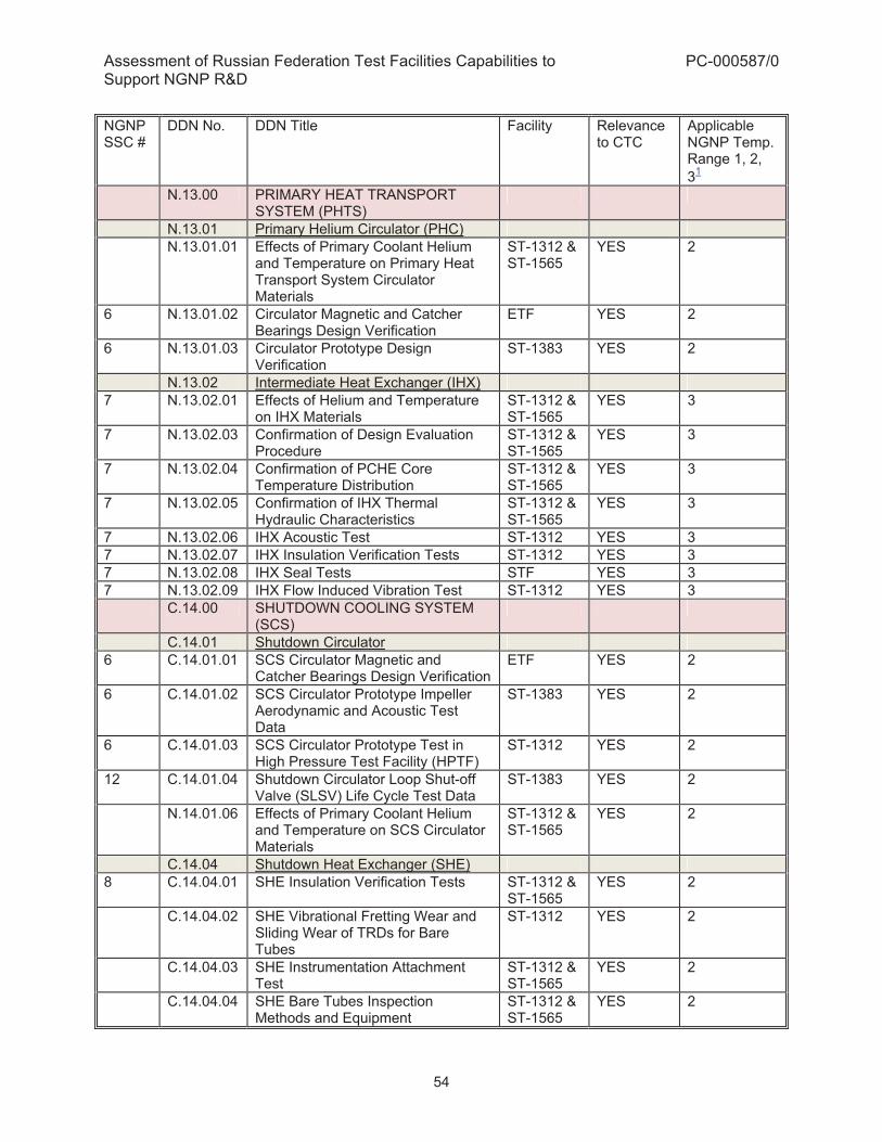
Assessment of Russian Federation Test Facilities Capabilities to Support NGNP R&D
PC-000587/0
54
NGNP SSC #
DDN No. DDN Title Facility Relevance to CTC
Applicable NGNP Temp. Range 1, 2, 31
N.13.00 PRIMARY HEAT TRANSPORT SYSTEM (PHTS)
N.13.01 Primary Helium Circulator (PHC) N.13.01.01 Effects of Primary Coolant Helium
and Temperature on Primary Heat Transport System Circulator Materials
ST-1312 & ST-1565
YES 2
6 N.13.01.02 Circulator Magnetic and Catcher Bearings Design Verification
ETF YES 2
6 N.13.01.03 Circulator Prototype Design Verification
ST-1383 YES 2
N.13.02 Intermediate Heat Exchanger (IHX) 7 N.13.02.01 Effects of Helium and Temperature
on IHX Materials ST-1312 & ST-1565
YES 3
7 N.13.02.03 Confirmation of Design Evaluation Procedure
ST-1312 & ST-1565
YES 3
7 N.13.02.04 Confirmation of PCHE Core Temperature Distribution
ST-1312 & ST-1565
YES 3
7 N.13.02.05 Confirmation of IHX Thermal Hydraulic Characteristics
ST-1312 & ST-1565
YES 3
7 N.13.02.06 IHX Acoustic Test ST-1312 YES 3 7 N.13.02.07 IHX Insulation Verification Tests ST-1312 YES 3 7 N.13.02.08 IHX Seal Tests STF YES 3 7 N.13.02.09 IHX Flow Induced Vibration Test ST-1312 YES 3 C.14.00 SHUTDOWN COOLING SYSTEM
(SCS)
C.14.01 Shutdown Circulator 6 C.14.01.01 SCS Circulator Magnetic and
Catcher Bearings Design Verification ETF YES 2
6 C.14.01.02 SCS Circulator Prototype Impeller Aerodynamic and Acoustic Test Data
ST-1383 YES 2
6 C.14.01.03 SCS Circulator Prototype Test in High Pressure Test Facility (HPTF)
ST-1312 YES 2
12 C.14.01.04 Shutdown Circulator Loop Shut-off Valve (SLSV) Life Cycle Test Data
ST-1383 YES 2
N.14.01.06 Effects of Primary Coolant Helium and Temperature on SCS Circulator Materials
ST-1312 & ST-1565
YES 2
C.14.04 Shutdown Heat Exchanger (SHE) 8 C.14.04.01 SHE Insulation Verification Tests ST-1312 &
ST-1565 YES 2
C.14.04.02 SHE Vibrational Fretting Wear and Sliding Wear of TRDs for Bare Tubes
ST-1312 YES 2
C.14.04.03 SHE Instrumentation Attachment Test
ST-1312 & ST-1565
YES 2
C.14.04.04 SHE Bare Tubes Inspection Methods and Equipment
ST-1312 & ST-1565
YES 2

Assessment of Russian Federation Test Facilities Capabilities to Support NGNP R&D
PC-000587/0
55
NGNP SSC #
DDN No. DDN Title Facility Relevance to CTC
Applicable NGNP Temp. Range 1, 2, 31
8 C.14.04.05 SHE Shroud Seal Test STF YES 2 8 C.14.04.06 Acoustical Response of the SHE
Helical Bare Tube Bundle ST-1312 YES 2
8 C.14.04.07 SHE Inlet Flow and Temperature Distribution Test
ST-1312 & ST-1565
YES 2
8 C.14.04.08 SHE Tube Bundle Local Heat Transfer and Flow Resistance Characteristics
Air test facility
YES 2
C.14.04.12 Effects of Primary Coolant Helium and Temperature on Shutdown Cooling System Heat Exchanger Materials
ST-1312 & ST-1565
YES 2
C.16.00 REACTOR CAVITY COOLING SYSTEM (RCCS)
9 C.16.00.04 RCCS Cooling Panel Heat Transfer Coefficient and Friction Factor
Air test facility
YES 2
C.16.00.06 Buoyancy Induced Fluid Mixing in a High Aspect Ratio Cavity
ST-1312 & ST-1565
YES 2
M.21.00 PRIMARY HEAT TRANSPORT SYSTEM (PHTS) – Steam Generator –Steam-cycle MHTGR3
M.21.00.01 Determine Core Exit Plenum and Hot Duct Flow Field
ST-1312 & ST-1565
YES 2
M.21.02 Steam Generator (SG) M.21.02.04 Tube Bundle Acoustic Test ST-1312 YES 2 M.21.02.08 Air Flow Test. Air test
facility 2
M.21.02.10 Steam Generator Insulation Verification Tests.
ST-1312 YES 2
M.21.02.11 Vibration Fretting Wear and Sliding Wear protection Tests
ST-1312 2
M.21.02.12 Tube Wear Protection Device Tests ST-1312 & ST-1565
2
M.21.02.13 Shroud Seal Test STF 2 M.21.02.14 Lead-In, Lead-Out, Expansion Loop
Mockup Test. ST-1312 & ST-1565
2
M.21.02.15 Flow Induced Vibration Test ST-1312 YES 2 C.31.00 REACTOR PROTECTION SYSTEM
(RPS)
C.31.01 Safety Protection and Instrumentation
15 C.31.01.01 Verify Helium Mass Flow Measurement Instrumentation
ST-1312 & ST-1565
2
C.31.01.02 Verify Conduction Cooldown ST-1312 & 2
3 System numbering for 350 MW steam-cycle MHTGR and 600 MW direct-cycle GT-MHR is not completely consistent: for the MHTGR, System 21 is Heat Transport System; for the GT-MHR, System 21 is Fuel Handling and Storage System.

Assessment of Russian Federation Test Facilities Capabilities to Support NGNP R&D
PC-000587/0
56
NGNP SSC #
DDN No. DDN Title Facility Relevance to CTC
Applicable NGNP Temp. Range 1, 2, 31
Temperature Monitoring Instrumentation
ST-1565
C.34.00 PLANT CONTROL, DATA AND INSTRUMENTATION SYSTEM (PCD&IS)
C.34.01 Nuclear Island Control and Instrumentation
C.34.01.01 Verify Core Inlet and Outlet Helium Temperature Measurement Instrumentation
ST-1312 & ST-1565
2
N.41.00 POWER CONVERSION SYSTEM (PCS)
N.41.04 Ducts and Seals STF 2 N.42.00 SECONDARY HEAT TRANSPORT
SYSTEM (SHTS)
N.42.01 SHTS Circulator (Secondary Circulator DDNs are
covered by Primary Helium Circulator DDNS due to design similarity)
ST-1383 YES 2
N.42.02 Isolation Valves 12 N.42.02.01 Effects of Primary Coolant Helium
and Temperature on SHTS Piping and Valve Materials
ST-1312 & ST-1565
YES 2
12 N.42.02.02 High Temperature Isolation Valve Prototype Design Verification
ST-1312 & ST-1565
YES 2
N.45.04 High Temperature Electrolysis (HTE) Plant Supporting Equipment
N.45.04.01 HTE Steam Generator/Super heater ST-1312 & ST-1565
YES 2
N.45.04.02 HTE Heat Exchangers ST-1312 & ST-1565
YES 2

Assessment of Russian Federation Test Facilities Capabilities to Support NGNP R&D
PC-000587/0
57
Table 4-2. NGNP DDNs Relevant to Capabilities of Other RF Facilities DDN No. DDN Title Applicable RF Facility C.07.00 FUEL/FISSION PRODUCT C.07.02 Fuel Performance C.07.02.01 Coating Material Property Data RBT-6, SM3 C.07.02.02 Defective Particle Performance Data RBT-6, SM3 C.07.02.03 Thermochemical Performance Data for Fuel RBT-6, SM3 C.07.02.04 Fuel Compact Thermophysical Properties RBT-6, SM3 and PIE C.07.02.05 Normal Operation Fuel Performance Validation Data RBT-6, SM3 and PIE C.07.02.06 Accident Fuel Performance Validation Data PIH C.07.02.07 Fuel Proof Test Data RBT-6, SM3 and PIE/PIH N.07.02.08 Irradiation Performance of LEU UO2 (NFI extended
burnup fuel)) RBT-6, SM3 and PIE
N.07.02.09 Accident Performance of LEU UO2 (NFI extended burnup fuel))
PIH
C.07.03 Radionuclide Transport C.07.03.01 Fission Gas Release from Core Materials RBT-6, SM3 and PIH C.07.03.02 Fission Metal Effective Diffusivités in Fuel Kernels RBT-6, SM3 and PIH C.07.03.03 Fission Product Effective Diffusivities in Particle Coating RBT-6, SM3 and PIH C.07.03.04 Fission Product Diffusivities/Sorptivities in Graphite RBT-6, SM3, PIH and lab
sorption measurements at RRC-KI
C.07.03.05 Tritium Permeation in Heat Exchanger Tubes Lab permeation measurements at RRC-KI
C.07.03.06 Tritium Transport in Core Materials PIH; lab sorption measurements at RRC-KI
C.07.03.07 Radionuclide Deposition Characteristics of Structural Materials
Lab sorption measurements at RRC-KI/Lutch, TsGS
C.07.03.08 Decontamination Protocols for Turbine Alloys Lab measurements at RRC-KI/Lutch
C.07.03.09 Radionuclide Reentrainment Characteristics for Dry Depressurization
TsGS
C.07.03.10 Radionuclide Removal Characteristics for Wet Depressurization
TsGS with H2O injection capability
C.07.03.11 Characterization of the Effects of Dust on Radionuclide Transport
TsGS
C.07.03.12 Fission Product Transport in a Vented Low-Pressure Containment
PG-1, Lab sorption measurements at RRC-KI; Integral test facility coupled to PG-1
C.07.03.13 Decontamination Efficiency of Pressure Relief Train Filter Lab measurements at RRC-KIC.07.03.14 Fission Gas Release Validation Data SM-3, RBT-6, PG-1 C.07.03.15 Fission Metal Release Validation Data SM-3, RBT-6, PG-1 C.07.03.16 Plateout Distribution Validation Data PG-1 C.07.03.17 Radionuclide "Liftoff" Validation Data PG-1 C.07.03.18 Radionuclide "Washoff" Validation Data PG-1 with H2O injection
capability N.07.03.19 Physical and Chemical Forms of RNs Released during
Core Heatup PIH furnace
N.07.03.20 RN Sorptivities of VLPC Surfaces Lab measurements at RRC-KI

Assessment of Russian Federation Test Facilities Capabilities to Support NGNP R&D
PC-000587/0
58
DDN No. DDN Title Applicable RF Facility N.07.03.21 Qualification of Coatings with High Iodine Sorptivity Lab measurements at RRC-KI
N.07.03.22 Validation Data for Predicting RN Transport in VLPC Integral test facility coupled to PG-1
N.07.03.23 Tritium Release from TRISO Particles SM-3, RBT-6, PIH N.07.03.24 Tritium Release from Control Materials SM-3, RBT-6 C.07.04 Core Corrosion Data C.07.04.03 Core Corrosion Methods Validation Data PG-1 with H2O ingress
capability C.11.00 REACTOR System (RS) C.11.01 Neutron Control System N.11.01.12 Control Rod (CR) & Reactor Shut down System Material
(RSSM) Guide Tubes - Effect of Low Level Irradiation on Composite Materials
SM-3, RBT-6
C.11.02 Reactor Internals (RI) and Hot Duct N.11.02.11 Irradiation Effects on Metallic Reactor Internals Materials SM-3, RBT-6 N.11.02.12 Irradiation Effects on Hot Duct Metals SM-3, RBT-6 N.11.02.17 Hot Duct-Effect of Low Level Irradiation on Composite
Materials SM-3, RBT-6
N.11.02.21 UPS-Effect of Low Level Irradiation on Composite Materials
SM-3, RBT-6
N.11.02.25 UCR-Effect of Low Level Irradiation on Composite Materials
SM-3, RBT-6
C.11.03 Reactor Core C.11.03.14 Graphite Irradiation Induced Dimensional Change Data SM-3, RBT-6 C.11.03.15 Graphite Irradiation Induced Creep Data SM-3, RBT-6 C.11.03.19 Graphite Corrosion Data for Methods Validation PG-1 C.11.03.23 Graphite Oxidation Data for Postulated Accidents TsGS C.11.03.51 Integral Nuclear Data Measurement at Temperature for
GT-MHR Physics Methods Validation ASTRA
C.11.03.52 Critical Experimental Data for GT-MHR Physics Methods Validation
ASTRA
N.11.03.53 Control Rod - Effect of High Level Irradiation on Composite Materials
SM-3, RBT-6
C.12.00 VESSEL SYSTEM (VS) C.12.01 Vessels N.12.01.01 Irradiation Data for Reactor Vessel Materials (modified
9Cr-lMo, SA-387 Grade 91, Class 2 Plate and SA-336 Grade F91 Forging)
SM-3, RBT-6
N.12.01.05 Irradiation Data for Reactor Vessel Material, (2¼ Cr – 1Mo)
SM-3, RBT-6
C.14.00 SHUTDOWN COOLING SYSTEM (SCS) C.14.01 Shutdown Circulator N.14.01.05 Irradiation Effects on SCS Circulator Materials SM-3, RBT-6 C.14.04 Shutdown Heat Exchanger (SHE) C.14.04.11 Irradiation Effects on Shutdown Cooling System Heat
Exchanger Materials SM-3, RBT-6
C.34.00 PLANT CONTROL, DATA AND INSTRUMENTATION SYSTEM (PCD&IS)
C.34.01 Nuclear Island Control and Instrumentation C.34.01.02 Verify Plateout Probe Operation PG-1
Assessment of Russian Federation Test Facilities Capabilities to Support NGNP R&D
PC-000587/0
59
5. POTENTIAL TEST PROGRAMS UTILIZING RF TEST FACILITIES 5.1. Preliminary Assessment of Candidate Test Programs for OKBM Test Facilities The candidate test programs presented in Section 5.1 were derived from an evaluation of the available information on the OKBM facilities. The facilities are described in Section 3.1, and an assessment of their relevancy to the NGNP DDNs is given in Section 4. 5.1.1. Study of Thermo-Hydraulic Performance and Flow Distribution Investigation of the thermal-hydraulic performance of steam generators and other heat exchangers can be performed at OKBM. In particular, the OKBM test facilities for steam generator model and multipurpose research complex described in Sections 3.1.1 and 3.1.2 can be utilized for such investigations. Testing of a large-size steam generator model and a heat-exchanger model, as well as thermo-hydraulic tests of the GT-MHR recuperator, have been conducted previously in these facilities, and there is a well established basis at these facilities for experimental studies of related NGNP Project issues. The study of hydraulic performance and the flow distribution in the reactor structural elements can be done for NGNP as well. The air test facility described in Section 3.1.3 could be used to conduct such a study. This test facility was designed to include experiments on the hydraulic performance of reactor structural elements and other components. The test programs addressed in this subsection would support several of NGNP DDNs listed in Section 4. These DDNs are C.11.03.44, C.11.03.45, N.13.02.05, C.14.04.07, C.14.04.08, C.16.00.04, C.16.00.06, M.21.00.01, M.21.02.08, M.21.02.14, C.31.01.01, C.31.01.02, C.34.01.01, N.45.04.01, and N.45.04.02. 5.1.2. Investigation of Vibration Characteristics Another test program applicable to NGNP would be a study of the vibration characteristics of heat exchangers, reactor internals, and other structural elements. The OKBM test facility for steam generator model and high-temperature heat exchangers (described in Section 3.1.1) was designed with the capability to investigate vibration characteristics, and it is a suitable facility that can be utilized for related studies within the NGNP Project. The test program addressed in this subsection would support the following NGNP DDNs listed in Section 4 - C.11.01.08, C.11.03.01, C.11.03.02, N.13.02.09, C.14.04.02, M.21.02.11, and M.21.02.15.

Assessment of Russian Federation Test Facilities Capabilities to Support NGNP R&D
PC-000587/0
60
5.1.3. Structural Materials Testing Testing in a helium environment and high-temperature effects testing on the structural materials of heat-exchangers, the hot duct, and other components will be necessary for NGNP. This testing could be conducted in the OKBM test facility for steam generator model and high-temperature heat exchangers (described in Section 3.1.1), which have the necessary capabilities. These facilities could also be used for studies of temperature effects on the structural materials. The test program addressed in this subsection would support the following NGNP DDNs listed in Section 4 - N.11.02.10, N.11.02.13, N.11.02.19, N.11.02.23, N.11.02.27, N.13.01.01, N.13.02.01, N.14.01.06, C.14.04.12, and N.42.02.01. 5.1.4. Aerodynamic Testing of Equipment Aerodynamic testing of equipment and structural elements, or the corresponding models, is another important testing area for NGNP. The air test facility described in Section 3.1.3 can be utilized for such testing. Aerodynamic testing is the main capability of this test facility, and it can be applied to heat exchangers, gas coolers, circulators, and steam generators. Characterization of the aerodynamic properties of structural elements, or models thereof, in air is generally sufficient for determining aerodynamic behavior in a helium environment. The test program addressed in this subsection would support the following NGNP DDNs listed in Section 4 - C.11.03.44, C.11.03.45, C.14.01.02, C.14.04.08, C.16.00.04, and M.21.02.08. 5.1.5. Testing of Rotating Machinery with Bearings Testing of rotating machinery with oil or electromagnetic bearings can be done at the main circulator test facility described in Section 3.1.4. The electromagnetic bearings and catcher (auxiliary) bearings are important for the proper design of a gas circulator, and this OKBM facility has capabilities for bearing testing, as described in Section 3.1.4. The test program addressed in this subsection would support the following NGNP DDNs listed in Section 4 - N.13.01.02, C.14.01.01, and M.21.01.01.
Assessment of Russian Federation Test Facilities Capabilities to Support NGNP R&D
PC-000587/0
61
5.1.6. Gas Valve Testing The main circulator facility described in the Section 3.1.4 could be used for experiments on the gas valves. This facility contains the necessary equipment for experimental studies of the performance of valves of various diameters. The test program addressed in this subsection would support the following NGNP DDNs listed in Section 4 - C.14.01.04, and N.42.02.02. 5.1.7. Gas Circulator Technology Development The test facility described in Section 3.1.4 could be employed for studies of the gas-circulator technical characteristics. This facility is designed to conduct a number of tests associated with gas circulators such as dynamic and thermal studies, measuring the main technical and electromechanical characteristics of the associated electric motor, testing and tune-up of the control system and the information-measuring system (for collecting and processing the information). The test program addressed in this subsection would support the following NGNP DDNs listed in Section 4 - N.13.01.03, C.14.01.02, C.14.01.03, M.21.01.02, and N.42.01. 5.1.8. Testing of Gas Coolers Gas cooler design will depend on obtaining the necessary thermo-hydraulic and heat transfer data. The steam generator and high-temperature heat exchanger facility and the multipurpose research complex (described in Sections 3.1.1 and 3.1.2) have the demonstrated capability to study the performance of gas coolers and could be used to obtain the necessary experimental data. The test program addressed in this subsection would support the following NGNP DDNs listed in Section 4 - C.16.00.04, and C.16.00.06. 5.1.9. Testing of Hot Duct The test facilities described in Sections 3.1.1, 3.1.2 and 3.1.3 could be used for testing of the hot duct assembly and hot duct components. The hot duct is located within a cross vessel which connects the reactor and steam generator vessels. The cross vessel has an annular arrangement with hot helium flowing from the reactor to the steam generator through the inner hot duct and return helium flowing from the steam generator to the reactor through the annulus between the cross vessel and the hot duct. The hot duct is insulated to reduce heat transfer
Assessment of Russian Federation Test Facilities Capabilities to Support NGNP R&D
PC-000587/0
62
from the hot leg to the cold leg and to protect its base material (Alloy 800H). In addition to heat transfer and fluid flow tests, the hot duct needs to be tested for mixing and vibrations. More details on this proposed test program are given in Appendix B. This testing was proposed as a means to help OKBM develop cost and schedule estimates for refurbishing the key facilities. The test program addressed in this subsection would support the following NGNP DDNs listed in Section 4 - B13.03.25, B.13.03.28, B13.03.29, C.11.02.02, C.11.02.13, C.11.02.14, and C.11.02.15. 5.1.10. Investigation of Accident Scenarios Experiments relevant to accident scenarios associated with primary-circuit pressure loss and water ingress in the primary circuit can also be conducted. The OKBM multipurpose research complex (described in the Section 3.1.2) could be utilized for this purpose. This test facility has a capability to investigate pressure loss and water ingress. The studies could include heat transfer and temperature distribution.
5.2. Candidate Test Programs with the Use of RRC-KI, NIIAR and NPO Lutch Facilities The DDNs potentially applicable to RRC-KI and NIIAR are listed in Table 4-2 in Section 4. Potential test programs for these facilities are in the areas of fuel performance, radionuclide transport and deposition, neutron control system, reactor internals, hot duct, reactor core, vessels, and instrumentation. Detailed descriptions of the test programs can be developed following coordination with the management of these RF institutes.
Assessment of Russian Federation Test Facilities Capabilities to Support NGNP R&D
PC-000587/0
63
6. QUALITY ASSURANCE NEEDS FOR THE RF FACILITIES OKBM’s Quality Assurance (QA) Program is described in OKBM Quality Management System Manual QM 1-2008 and is certified by the International Organization for Standardization to comply with standard ISO 9001:2000, Quality Management Systems – Requirements. The OKBM QA Program is also required to comply with the Russian Federal Regulation NP-011-99, Quality Assurance Requirements for Nuclear Plants and with International Atomic Energy Agency (IAEA) Safety Standard No. 50-C/SG-Q, Quality Assurance for Safety in Nuclear Power Plants and other Nuclear Installations. For the purposes of conducting component testing to U.S. standards at any of the OKBM facilities described herein, the OKBM Quality Assurance Program must also comply with American Society for Mechanical Engineers (ASME) standard NQA-1-2008, Quality Assurance Requirements for Nuclear Facility Applications, as applicable to the testing being performed. Therefore, an evaluation of the OKBM QA program and its applicability to any proposed testing will be required if these facilities were to be used to support NGNP technology development.
Currently, GA is in the process of auditing the OKBM QA Program as part of its contract with DOE-NNSA for Technical Support Services on the GT-MHR Plutonium Disposition Program. The audit has two objectives. The first objective is to verify compliance with DOE-OKBM General Order Agreement (GOA) which requires OKBM to comply with nuclear QA requirements imposed by Russian Federal Standards. The second objective is to assess to what extent the OKBM QA Program and supplementing procedures comply with U.S. QA requirements described in NQA-1-2008.
The audit is being performed in two steps. The first step is a desk evaluation of OKBM QA documentation in San Diego, and the second step is an on-site audit at the OKBM facilities. The initial desk evaluation of OKBM QA documentation available at GA was completed in May, 2009 and the Initial Desk Evaluation Report was issued on May 7, 2009 (Ref. 8). The conclusions from the initial evaluation were:
� The OKBM QA Program complies with the GOA and the QA requirements of Russian Federal Regulation NP-011-99 and of IAEA-50-C/SG-Q
� GA needs to obtain and review a copy of the latest OKBM QA Manual � A more detailed review of OKBM Quality Manual and implementing procedures is
needed to evaluate the degree of compliance with ISO 9001:2000 and NQA-1-2008 Requirements, and to determine what changes need to be made so that work in the RF would meet the applicable U.S. QA requirements
Assessment of Russian Federation Test Facilities Capabilities to Support NGNP R&D
PC-000587/0
64
� Compliance with the U.S. QA requirements will be verified during the on-site audit of OKBM
Since the initial Desk Evaluation Report, GA received English and Russian versions of OKBM Quality Systems Manual QM-2008 and verified that the OKBM Quality Systems Manual QM 1-2008 complies with the ISO 9001-2000 certification. GA is in the process of performing a detailed evaluation of the OKBM Quality Manual and implementing procedures to determine the degree of compliance with NQA-1-2008. GA intends to conduct the on-site QA audit of OKBM facilities once appropriate logistics for such a visit is provided by OKBM. The audit report is expected to be available 30 days after completion of the on-site audit.

Assessment of Russian Federation Test Facilities Capabilities to Support NGNP R&D
PC-000587/0
65
7. CONCLUSIONS The NGNP Project will require substantial technology development and test data to satisfy the Design Data Needs and to advance the Technology Readiness Levels of critical reactor systems, subsystems, and components. A potential approach to obtaining these data is to utilize existing facilities in the RF that have the capability to simulate the operating conditions of the NGNP systems. This report provides an assessment of the capabilities of several existing test facilities in the RF that potentially could be used to support NGNP technology development. The facilities are located at OKBM, RRC-KI, NIIAR, and NPO Lutch. Existing NGNP DDNs have been reviewed and a number of DDNs relevant to the described test facilities have been identified. It has been concluded that the OKBM facilities could be used for testing of non-nuclear components associated with the Reactor System, Primary Heat Transport System, Shutdown Cooling System, Reactor Cavity Cooling System, Steam Generator, Instrumentation System, and Secondary Heat Transport System. It has also been concluded that the RRC-KI, NIIAR and NPO Lutch facilities can potentially be applicable to the NGNP Program in the areas of fission product transport, fuel, and reactor systems. Potential test programs involving the RF test facilities have been identified, and include thermo-hydraulic performance, vibration characteristics, aerodynamic testing, gas valves, gas coolers, accident scenarios, and testing of the hot duct, as well as investigations of fuel performance and radionuclide transport and deposition. A physical inspection of OKBM test facilities was conducted by a GA-led U.S. team during November 2009. The U.S. team concluded that three of the four OKBM facilities could potentially be useful for NGNP technology development, but that substantial effort to reactivate and upgrade the facilities would be needed. Specific tests as needed to satisfy the DDNs associated with the hot duct assembly have been described (Appendix B) for consideration by OKBM as a means to help OKBM develop cost and schedule estimates for refurbishing the key facilities. OKBM has provided ROM cost estimates for refurbishing its facilities ST-1312 (Steam Generator Model / Heat Exchanger) and ST-1565 (Multipurpose Research Complex), with the total estimated costs being $28 million and $7.1 million, respectively. OKBM estimates that 2.5 to 3 years would be required to restore these facilities to their design condition. Each RF facility would have to be evaluated on a case-by-case basis with respect to the required upgrades and modifications in order to make a decision on its potential use for the NGNP Program.

Assessment of Russian Federation Test Facilities Capabilities to Support NGNP R&D
PC-000587/0
66
8. REFERENCES 1. GT-MHR Technology Development in the Russian Federation in 2008 Commonality with
NGNP Objectives, PC-000585, Rev. 0, General Atomics, San Diego, CA, March 2009. 2. Technology Development Road Mapping Report for NGNP with 750�C Reactor Outlet
Helium Temperature, PC-000586, Rev. 0, General Atomics, San Diego, CA, May 2009. 3. NGNP Technology Development Road Mapping Report, PC-000580, Rev. 0, General
Atomics, San Diego, CA, December 2008. 4. Fission Product Transport Technology Development Plan, 2007, GT-MHR Product 02.02-
129.01B 5. Fuel Development Plan, Rev. 1, 2009, GT-MHR Product 08.04-001.05A 6. Reactor Technology Demonstration Program Plan, 2005, GT-MHR Product 08.03-006.03A 7. Reconciliation of NGNP DDNs with NRC PIRTs, PC-000570, Rev. 0, General Atomics, San
Diego, CA, September 2008. 8. Desk Evaluation of OKBM QA Program, Audit No: 09001A, May 2009, Under Revision.
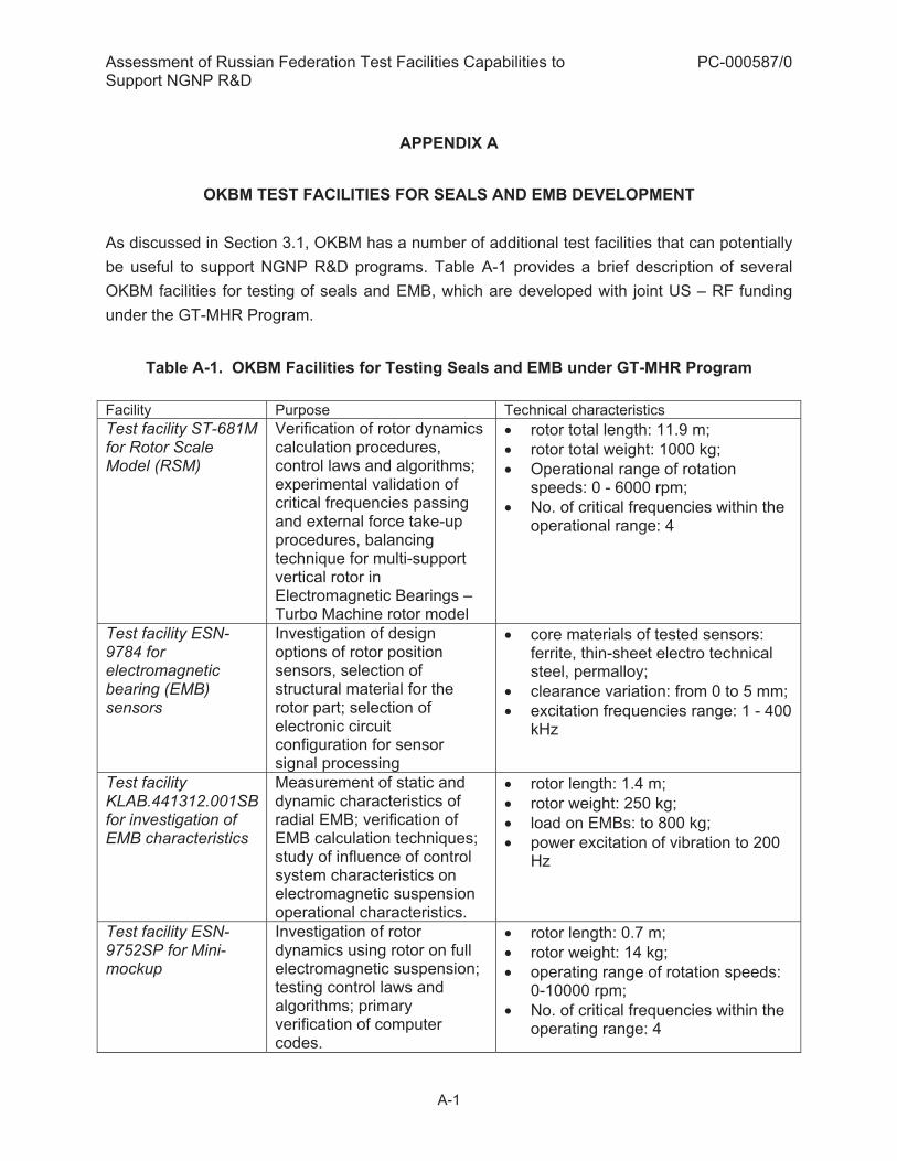
Assessment of Russian Federation Test Facilities Capabilities to Support NGNP R&D
PC-000587/0
A-1
APPENDIX A
OKBM TEST FACILITIES FOR SEALS AND EMB DEVELOPMENT
As discussed in Section 3.1, OKBM has a number of additional test facilities that can potentially be useful to support NGNP R&D programs. Table A-1 provides a brief description of several OKBM facilities for testing of seals and EMB, which are developed with joint US – RF funding under the GT-MHR Program.
Table A-1. OKBM Facilities for Testing Seals and EMB under GT-MHR Program Facility Purpose Technical characteristics Test facility ST-681M for Rotor Scale Model (RSM)
Verification of rotor dynamics calculation procedures, control laws and algorithms; experimental validation of critical frequencies passing and external force take-up procedures, balancing technique for multi-support vertical rotor in Electromagnetic Bearings – Turbo Machine rotor model
� rotor total length: 11.9 m; � rotor total weight: 1000 kg; � Operational range of rotation
speeds: 0 - 6000 rpm; � No. of critical frequencies within the
operational range: 4
Test facility ESN-9784 for electromagnetic bearing (EMB) sensors
Investigation of design options of rotor position sensors, selection of structural material for the rotor part; selection of electronic circuit configuration for sensor signal processing
� core materials of tested sensors: ferrite, thin-sheet electro technical steel, permalloy;
� clearance variation: from 0 to 5 mm; � excitation frequencies range: 1 - 400
kHz
Test facility KLAB.441312.001SB for investigation of EMB characteristics
Measurement of static and dynamic characteristics of radial EMB; verification of EMB calculation techniques; study of influence of control system characteristics on electromagnetic suspension operational characteristics.
� rotor length: 1.4 m; � rotor weight: 250 kg; � load on EMBs: to 800 kg; � power excitation of vibration to 200
Hz
Test facility ESN-9752SP for Mini-mockup
Investigation of rotor dynamics using rotor on full electromagnetic suspension; testing control laws and algorithms; primary verification of computer codes.
� rotor length: 0.7 m; � rotor weight: 14 kg; � operating range of rotation speeds:
0-10000 rpm; � No. of critical frequencies within the
operating range: 4

Assessment of Russian Federation Test Facilities Capabilities to Support NGNP R&D
PC-000587/0
A-2
Facility Purpose Technical characteristics Test facility for EMB Lead-outs and Electrical insulation Test Facility
Tests of electric and mechanical properties of EMB lead-outs and winding insulation in helium under various pressure drops.
� working fluid: helium; � helium operating pressure: 10 MPa; � helium temperature in the autoclave:
20 to 120�C
Test facility BM 890 for air tests of TC stator seal mockup
Measuring air leaks across the seal depending on pressure drop and skew of internal casing, and under vibration.
� working fluid: air; � pressure: 0 to 0.6 MPa; � temperature: 25��; � pressure drop: 0.01 to 0.4 MPa;� diameter of sealed surface: 1 m
Test facility KLAB.441372.002 TC stator seal mockup tests in helium
Measuring air and helium leaks across the seal depending on pressure drop on the seal and various temperatures and positions of the seal internal casing
� working fluid: air / helium � temperature: 50 to 550�� � pressure: to 7.6 MPa � air flow rate: 6000 kg/h � helium flow rate: 2400 kg/h � diameter of sealed surface: 1 m
Test facility for full-scale TC stator seal samples
Acceptance tests of full-scale TC stator seal samples
� working fluid: air / helium � temperature: to 50�C � pressure: to 7.6 MPa � air flow rate: 6000 kg/h � helium flow rate: 2400 kg/h � diameter of sealed surface: from 1
m to 3200 mTest facility 2395p 00SP for dry gas seal
Multipurpose test facility for tests and verification of various designs of dry gas seals under GT-MHR conditions
� shaft rotation speed: to 6000 rpm; � shaft diameter: 230 to 450 mm; � working fluid: helium; � working fluid temperature: to 200ºC; � working fluid pressure: to 7 MPa

Assessment of Russian Federation Test Facilities Capabilities to Support NGNP R&D
PC-000587/0
B-1
APPENDIX B
PROPOSED HOT DUCT TESTS AT OKBM
The hot duct is located within a cross vessel that connects the reactor and steam generator vessels. An elevation view and the arrangement of the hot duct are shown in Figures B-1 and B-2, respectively. The duct has an annular arrangement with hot helium flowing from the reactor to the steam generator through the inner hot duct and return helium flowing through an annular space from the steam generator to the reactor. The hot duct is insulated to reduce heat transfer from hot leg to cold leg and to protect its base material (Alloy 800H).
Figure B-1. Hot Duct Elevation View

Assessment of Russian Federation Test Facilities Capabilities to Support NGNP R&D
PC-000587/0
B-2
Figure B-2. Hot Duct Arrangement
Experimental verification of the hot duct is critical because it has:
� The highest operating temperature � Potential for non uniform temperatures � Exposure to graphite dust and other particles � Difficulties in inspection during operation � Possibility of leaks from the hot to the cold leg � Heat transfer from the hot leg to the cold leg
The expected operating conditions for the hot duct are: Maximum Temperature: 750°C (could be increased later); Pressure: 7 MPa; Flow Rate: 160 kg/s to 280 kg/s. Applicable NGNP Design Data Needs are addressed in the Section 5.1 and listed in Table 4-1 of Section 4. The tests are proposed to be conducted in three stages: A) Component Level Tests During this phase, the hot duct, cover plate and insulation materials will be tested at operating temperature and pressure in helium with impurities (e.g. graphite powder) in an apparatus such as shown in Figure B-3. A gas temperature of 800°C is specified to account for hot streaks.

Assessment of Russian Federation Test Facilities Capabilities to Support NGNP R&D
PC-000587/0
B-3
Figure B-3. Component Level Test Schematic
The objective of these tests will be to:
� Verify insulation, cover and duct material compatibility � Verify insulation installation method � Determine environmental qualification of the insulation � Determine erosion and corrosion characteristics of the materials � Determine efficacy of the insulation for insulating the hot duct and limiting heat transfer
to the cold leg B) Acoustic and Flow Induced Vibration Tests The flow induced vibration test will include all relevant design details to 1/4th scale. The test will be conducted in an air wind tunnel with matching Mach number in operation. Frequency spectra and sound levels are to be determined as a function of Mach number. OKBM is to determine the facility design.

Assessment of Russian Federation Test Facilities Capabilities to Support NGNP R&D
PC-000587/0
B-4
C) Sub-system Level Testing Objective of these tests will be to:
� Verify leak detection � Verify the sub-system under the operating pressure.
A possible configuration for these tests is shown in Figure B-4.
Figure B-4. Sub-system Level Test Schematic
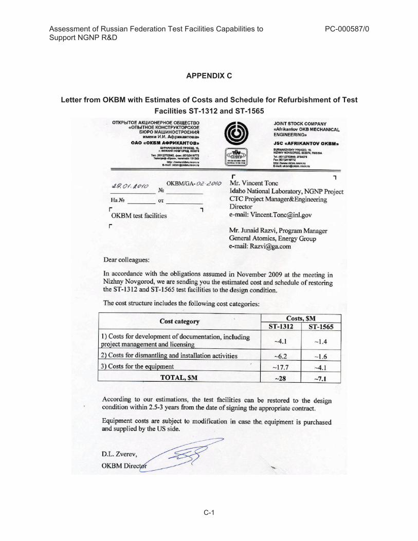
Assessment of Russian Federation Test Facilities Capabilities to Support NGNP R&D
PC-000587/0
C-1
APPENDIX C
Letter from OKBM with Estimates of Costs and Schedule for Refurbishment of Test Facilities ST-1312 and ST-1565

P.O. BOX 85608 SAN DIEGO, CA 92186-5608 (858) 455-3000