ngnp ctf feasibility recommendations r0-final documents/westinghouse/htgr component test...ngnp-ctf...
TRANSCRIPT

The INL is a U.S. Department of Energy National Laboratory operated by Battelle Energy Alliance.
INL/EXT-09-16080
NGNP with Hydrogen Production Preconceptual Design Study, HTGR Component Test Facility (CTF) Feasibility and Recommendations
Prepared by Westinghouse Electric Company, LLC for the Next Generation Nuclear Plant Project Jacques Holtzhausen February 2008

DISCLAIMER This information was prepared as an account of work sponsored by
Westinghouse Electric Company, LLC for an agency of the U.S. Government. Neither the U.S. Government nor any agency thereof, nor any of their employees, makes any warranty, expressed or implied, or assumes any legal liability or responsibility for the accuracy, completeness, or usefulness, of any information, apparatus, product, or process disclosed, or represents that its use would not infringe privately owned rights. References herein to any specific commercial product, process, or service by trade name, trade mark, manufacturer, or otherwise, does not necessarily constitute or imply its endorsement, recommendation, or favoring by the U.S. Government or any agency thereof. The views and opinions of authors expressed herein do not necessarily state or reflect those of the U.S. Government or any agency thereof.

NGNP-CTF 20-CTF April 2008 Revision 0
NGNP and Hydrogen Production Preconceptual Design Study
HTGR Component Test Facility (CTF)Feasibility and Recommendations
APPROVALS
Function Printed Name and Signature Date
Author Jacques Holtzhausen
M-Tech Industrial, Ltd
February 14, 2008
Reviewer Jan van Ravenswaay
M-Tech Industrial, Ltd
February 14, 2008
Approval Edward Brabazon Shaw Environmental & Infrastructure, Inc.
February 14, 2008
Westinghouse Electric Company LLC Nuclear Power Plants Post Office Box 355
Pittsburgh, PA 15230-0355
�2008 Westinghouse Electric Company LLC All Rights Reserved

NGNP-CTF 20-CTF HTGR Component Test Facility (CTF) Recommendations
2 of 68
NGNP CTF Feasibility_Recommendations_R0-FINAL.doc April 2008
LIST OF CONTRIBUTORS
Name and Organization Date Edward Brabazon: Shaw Stone and Webster February 2008 Peter Wells: Shaw Stone and Webster February 2008 Andries Haasbroek : Westinghouse South Africa February 2008 Marius Fox : Westinghouse South Africa February 2008 Marius Janse van Vuuren: PBMR February 2008 Heinz Mittermaaier: PBMR February 2008 Riaan du Bruyn: M-Tech Industrial February 2008 Jaco van der Merwe: M-Tech Industrial February 2008 Kobus Olivier: M-Tech Industrial February 2008 Jannie Potgieter: M-Tech Industrial February 2008 Peet Venter: M-Tech Industrial February 2008 Schalk Prinsloo: M-Tech Industrial February 2008 Dan Mears: Technology Insights February 2008 Scott Penfield: Technology Insights February 2008 Fred Silady: Technology Insights February 2008
BACKGROUND INTELLECTUAL PROPERTY
Section Title Description
NONE NONE

NGNP-CTF 20-CTF HTGR Component Test Facility (CTF) Recommendations
3 of 68
NGNP CTF Feasibility_Recommendations_R0-FINAL.doc April 2008
REVISION HISTORY
RECORD OF CHANGES
Revision No. Revision Made by Description Date
A Jacques Holtzhausen M-Tech Industrial (Pty) Ltd
Final Draft 14 February 2008
0 S.A. Caspersson, Westinghouse Final Report 29 April 2008
APPLICABLE DOCUMENTS AND DATA
The following documents and data are applicable:
TITLE REFERENCE NUMBER
[1] “High Temperature Fluid Flows Test Facility White Paper,” NGNP Engineering, INL, September 2007
INL/EXT-07-13146
DOCUMENT TRACEABILITY
Created to support the following Document(s)
Document Number Revision
NONE NONE

NGNP-CTF 20-CTF HTGR Component Test Facility (CTF) Recommendations
4 of 68
NGNP CTF Feasibility_Recommendations_R0-FINAL.doc April 2008
TABLE OF CONTENTS LIST OF CONTRIBUTORS ....................................................................................................... 2
BACKGROUND INTELLECTUAL PROPERTY ................................................................... 2
REVISION HISTORY ................................................................................................................. 3
LIST OF TABLES ........................................................................................................................ 7
LIST OF FIGURES ...................................................................................................................... 8
ACRONYMS............................................................................................................................... 10
SUMMARY AND CONCLUSIONS ......................................................................................... 11
INTRODUCTION....................................................................................................................... 16
1. CTF MISSION NEED....................................................................................................... 18
2. CTF JUSTIFICATION ..................................................................................................... 21
3. CTF FUNCTIONAL AND OPERATIONAL REQUIREMENTS ............................... 24 3.1 MAIN CATEGORIES OF UNITS UNDER TEST...................................................................27
3.1.1 IHX COMPONENT TESTS .......................................................................................... 27 3.1.1.1 CTF IHX Operational Requirements: Westinghouse Vendor Team............. 27 3.1.1.2 CTF IHX Operational Requirements: General Atomics Vendor Team ........ 28 3.1.1.3 CTF IHX Operational Requirements: AREVA Vendor Team...................... 29
3.1.2 MIXING CHAMBER TEST.......................................................................................... 29 3.1.2.1 CTF Mixing Chamber Operational Requirements: Westinghouse Vendor
Team.............................................................................................................. 30 3.1.3 HIGH TEMPERATURE DUCT & INSULATION TESTING.................................. 30
3.1.3.1 CTF HTD&I Operational Requirements: Westinghouse Vendor Team ....... 30 3.1.3.2 CTF HTD&I Operational Requirements: AREVA Vendor Team ................ 30
3.1.4 STEAM GENERATOR TESTING............................................................................... 31 3.1.4.1 CTF SG Operational Requirements: Westinghouse Vendor Team............... 31 3.1.4.2 CTF SG Operational Requirements: General Atomics Vendor Team .......... 33
3.1.5 HELIUM CIRCULATOR.............................................................................................. 33 3.1.5.1 CTF Circulator Operational Requirements: Westinghouse Vendor Team.... 33 3.1.5.2 CTF Circulator Operational Requirements: General Atomics Vendor
Team.............................................................................................................. 33 3.1.5.3 CTF Circulator Operational Requirements: AREVA Vendor Team............. 33
3.1.6 VALVES TESTING ....................................................................................................... 34 3.1.6.1 CTF Valves Operational Requirements: General Atomics Vendor Team .... 34
3.1.7 AUXILIARY SYSTEMS................................................................................................ 34 3.1.8 CONTROL & INSTRUMENTATION......................................................................... 34
3.1.8.1 CTF C&I Operational Requirements: General Atomics Vendor Team ........ 34 3.1.9 OTHER HELIUM HEAT EXCHANGER TESTING REQUIREMENTS............... 34
3.1.9.1 CTF Operational Requirements: General Atomics Vendor Team ................ 35
NGNP-CTF 20-CTF HTGR Component Test Facility (CTF) Recommendations
5 of 68
NGNP CTF Feasibility_Recommendations_R0-FINAL.doc April 2008
3.1.10 GENERAL FUNCTIONS .............................................................................................. 35 3.2 SOUTH AFRICAN TEST FACILITIES...................................................................................36
3.2.1 THE HELIUM TEST FACILITY................................................................................. 36 3.2.1.1 Capabilities.................................................................................................... 37 3.2.1.2 Test Schedule ................................................................................................ 39 3.2.1.3 Possible Modifications .................................................................................. 39 3.2.1.4 Current Configuration ................................................................................... 40 3.2.1.5 Ability To Address CTF Mission Need ........................................................ 40
3.2.2 THE PEBBLE BED MICRO MODEL......................................................................... 41 3.2.2.1 Capabilities.................................................................................................... 41 3.2.2.2 Test Schedule ................................................................................................ 41 3.2.2.3 Possible Modifications And Current Configuration...................................... 41 3.2.2.4 Ability To Address CTF Mission Need ........................................................ 42
3.2.3 THE HEAT TRANSFER TEST FACILITY................................................................ 42 3.2.3.1 High Temperature Test Unit ......................................................................... 42
HTTU Capabilities....................................................................................... 42 HTTU Test Schedule ................................................................................... 43 HTTU Possible Modifications And Current Configuration......................... 43 HTTU Ability To Address CTF Mission Need............................................ 43
3.2.3.2 High Pressure Test Unit ................................................................................ 44 HPTU Capabilities ....................................................................................... 44 HPTU Test schedule .................................................................................... 45 HPTU Possible Modifications and Current Configuration .......................... 45 HPTU Ability to Address CTF Mission Need ............................................. 45
3.2.4 JUSTIFICATION CONCLUSION ............................................................................... 45 4. CTF CONFIGURATION RECOMMENDATIONS...................................................... 46 4.1 CONCEPT 1.................................................................................................................................48
4.1.1 FACILITY LAYOUT..................................................................................................... 49 4.1.2 PROS AND CONS .......................................................................................................... 52
4.2 CONCEPT 2.................................................................................................................................54 4.2.1 FACILITY LAYOUT..................................................................................................... 55 4.2.2 PROS AND CONS .......................................................................................................... 57
4.3 CONCEPT 3.................................................................................................................................58 4.3.1 PROS AND CONS .......................................................................................................... 59
4.4 CONCEPT RECOMMENDATION ..........................................................................................60 5. CTF COST ESTIMATE AND SCHEDULE................................................................... 62 5.1 COST ESTIMATE ......................................................................................................................63
5.1.1 CONCEPT 1 - COST SUMMARY ............................................................................... 64 5.1.2 CONCEPT 2 - COST SUMMARY ............................................................................... 65
5.2 SCHEDULE .................................................................................................................................66

NGNP-CTF 20-CTF HTGR Component Test Facility (CTF) Recommendations
6 of 68
NGNP CTF Feasibility_Recommendations_R0-FINAL.doc April 2008
5.2.1 SCHEDULE - CONCEPT 1........................................................................................... 67 5.2.2 SCHEDULE - CONCEPT 2........................................................................................... 68
APPENDIX A: DESIGN DATA NEEDS MATRIX ........................................................................A-1
APPENDIX B: SOUTH AFRICAN PBMR TEST FACILITIES................................................... B-1
APPENDIX C: LITERATURE STUDY ON OTHER FACILITIES.............................................C-1
APPENDIX D: CONCEPT 1 DETAILS...........................................................................................D-1
APPENDIX E: CONCEPT 2 DETAILS........................................................................................... E-1
APPENDIX F: DDNS TEST CONFIGURATIONS........................................................................ F-1
APPENDIX G: IHX TEST SPECIFICATION.................................................................................G-1
APPENDIX H: NGNP CTF COSTING ............................................................................................H-1

NGNP-CTF 20-CTF HTGR Component Test Facility (CTF) Recommendations
7 of 68
NGNP CTF Feasibility_Recommendations_R0-FINAL.doc April 2008
LIST OF TABLES Table 1: Helium Test Facility (HTF) Operational Conditions......................................................... 38
Table 2: Pebble Bed Micro Model Operational Conditions ............................................................ 41
Table 3: High Temperature Test Unit (HTTU) Operational Conditions ......................................... 42
Table 4: High Pressure Test Unit (HPTU) Operational Conditions ................................................ 44
Table 5: Concept 1 Cost Summary .................................................................................................. 64
Table 6: Concept 2 Cost Summary. ................................................................................................. 65

NGNP-CTF 20-CTF HTGR Component Test Facility (CTF) Recommendations
8 of 68
NGNP CTF Feasibility_Recommendations_R0-FINAL.doc April 2008
LIST OF FIGURES Figure 1: Component Test Facility Feasibility Study Work Plan Outline ................................... 17
Figure 2: Component Test Facility Justification Philosophy ....................................................... 21
Figure 3: Work flow diagram of the process that was followed to attain the Functional & Operational Requirements resulting in the Configuration Recommendation............... 25
Figure 4: High level process flow diagram of the Helium Test Facility Main Loop................... 37
Figure 5: Helium Test Facility (HTF) operational envelope (dark blue area) compared against a facility that will typically address the CTF F&ORs (grey area)................................... 39
Figure 6: High level process flow diagram of the possible modifications to the HTF Laboratory..................................................................................................................... 40
Figure 7: High Temperature Test Unit (HTTU) operational envelope (dark blue area) compared against a facility that will typically adress the CTF F&ORs (grey area)...................... 43
Figure 8: High Pressure Test Unit (HPTU) operational envelop (dark blue area) compared against a facility that will typically adress the CTF F&ORs (grey area)...................... 44
Figure 9: Work flow diagram of the process that was followed to recommend configurations of the CTF that will address all Mission Needs. ............................................................... 46
Figure 10: High level Process Flow Diagram of Concept 1 indicating all Technology Development Loops, Component Qualification Loop & Full Scale Circulator Loop.. 48
Figure 11: Conceptual physical layout of Technology Development Loop 1 indicating major components as found in the Process Flow diagram...................................................... 49
Figure 12: Conceptual layout side view of Technology Development Loop 1 ............................. 50
Figure 13: Conceptual floor plan view of Technology Development Loop 1 ............................... 50
Figure 14: Physical layout of Concept 1 showing the TDL, interconnecting Hot Header, CQL, CLT, allocated floor space and lay down areas............................................................ 51
Figure 15: Perspective view of the physical layout of Concept 1.................................................. 52
Figure 16: High level Process Flow Diagram of Concept 2 indicating Primary Loop, Secondary Loop, Steam Generator Loop & Full Scale Circulator Loop........................................ 54
Figure 17: Physical layout of Concept 2 (CQL 2) ......................................................................... 55

NGNP-CTF 20-CTF HTGR Component Test Facility (CTF) Recommendations
9 of 68
NGNP CTF Feasibility_Recommendations_R0-FINAL.doc April 2008
Figure 18: Floor plan layout of Concept 2(CQL 2) indicating major components as can be found in the Process Flow diagram......................................................................................... 56
Figure 19: Side view layout of Concept 2 (CQL 2) ....................................................................... 57
Figure 20: High level process flow diagram of Concept 3 indicating the Primary Loop, Secondary and Tertiary Loops as well as the Full Scale Circulator Test Loop.............................. 58
Figure 21: Schedule for Concept 1 indicating key dates and dependants...................................... 67
Figure 22: Schedule for Concept 2 indicating key dates and dependants...................................... 68

NGNP-CTF 20-CTF HTGR Component Test Facility (CTF) Recommendations
10 of 68
NGNP CTF Feasibility_Recommendations_R0-FINAL.doc April 2008
ACRONYMSASME American Society of Mechanical Engineers BEA Battelle Energy Alliance COTS Commercial Off the Shelf CTF Component Test Facility CTL Circulator Test Loop CQL Component Qualification Loop (as incorporated in Concept 1) CQL 2 Large Scale Component Qualification Loop (Concept 2) CTP Component Testing Program DDN Design Data Need DOE Department of Energy DRL Design Readiness Level FHS Fuel Handling System FOAKE First-Of-A-Kind-Engineering F&OR Functional and Operational Requirements HTF Helium Test Facility HTTF High Temperature Test Facility HTTU High Temperature Test Unit HPS Helium Purification System HPTU High Pressure Test Unit IET Integrated Effects Tests IHX Intermediate Heat Exchanger INL Idaho National Laboratory ISI In-Service Inspection LWR Light Water Reactor MSS Main Support System NHS Nuclear Heat Source NGNP Next Generation Nuclear Plant PHTS Primary Heat Transport System PCDR Pre-Conceptual Design Report PCS Power Conversion system PBMR DPP Pebble Bed Modular Reactor, Demonstration Power Plant PBMM Pebble Bed Micro Model RCS Reactivity Control System RFC Ready For Commissioning SET Separate Effect Tests SG Steam Generator SHTS Secondary Heat Transport System TBD To be defined TDL Technology Development Loop (as incorporated in Concept 1) TQC Testing, Qualification and Commissioning TRL Technology Readiness Level UUT Unit Under Test V&V Verification & Validation

NGNP-CTF 20-CTF HTGR Component Test Facility (CTF) Recommendations
11 of 68
NGNP CTF Feasibility_Recommendations_R0-FINAL.doc April 2008
SUMMARY AND CONCLUSIONS The Next Generation Nuclear Plant (NGNP) project is a US-based initiative to demonstrate the viability of using High Temperature Gas-Cooled Reactors (HTGR) in the production of heat for usage in a wide range of energy producing technologies. These technologies typically include electricity production, hydrogen production, salt water desalination and the like. This forms part of DOE’s long term vision of acknowledging the potential of using nuclear energy as opposed to burning fossil fuels to meet the growing demand for energy. This task was authorized by EPAct 2005 and charged Idaho National Laboratories (INL) with the responsibility of investigating and selecting the appropriate technology for supplying process heat at high temperatures (~950�C) using a nuclear heat source.
As part of this responsibility, INL initiated three pre-conceptual designs for the NGNP by different vendor teams. These designs included proposals for the complete system as well as related technology development and testing requirements. The vendor teams identified the major elements of developmental testing and the vendor reports focused mainly on the different heat transport systems and their associated components. In order to support the development of some of the high risk components that were identified in the reports, a dedicated component test facility (CTF) was proposed. Such a facility would be supportive of the NGNP with regard to technology development and risk mitigation in terms of schedule requirements and equipment qualification. Typical applications include primary and secondary heat transport systems testing, demonstration and developmental testing of commercial high temperature process heat applications (e.g., hydrogen production) and testing of NGNP specific control, maintenance and inspection philosophies.
The purpose of this study was to evaluate the feasibility of this envisioned CTF with regards to the following key areas:
� CTF Mission Need � CTF Justification � CTF Functional and Operational Requirements (F&ORs) � CTF Configuration Recommendations � CTF Cost Estimate and Schedule
The study was conducted by means of a work plan as illustrated in the figure below. The Design Data Needs, Technology Readiness Levels as well as Design Readiness Levels (DDNs, TRLs, DRLs) of all three vendor groups and the NGNP lifecycle requirements were used as inputs to establish the CTF Enveloping Philosophy.

NGNP-CTF 20-CTF HTGR Component Test Facility (CTF) Recommendations
12 of 68
NGNP CTF Feasibility_Recommendations_R0-FINAL.doc April 2008
DDNs
– T
RLs
-DR
Ls
CTF Report
NGNP
– L
ife c
ycle
re
quire
men
ts
Pre-conceptual Design Review (PCDR)
Vendor Group A- Westinghouse
Vendor Group B- AREVA
Vendor Group C- General Atomics
CTF Envelope philosophy
MissionNeed Justification F&OR
Cost & Schedule
Configuration Recommend
Component Test Facility Feasibility Study Work Plan Outline
The CTF Enveloping Philosophy was defined as:
The CTF is a technology development platform for components and systems in support of the NGNP program. In order for these technologies to be integrated into the NGNP, it will be required that full scale, representative size component tests be conducted on certain items or assemblies. These tests need to be done at NGNP representative conditions, with regards to pressure, flow rate and temperature.
The justification process for the CTF basically consisted of an in depth review of the mission need with specific reference to the Functional and Operational Requirements (F&ORs) that were developed as part of this task. The South African PBMR test facilities were used as basis for the analysis against the F&ORs and Mission Need. The analysis was performed in terms of the technical capability, timeframe utilization and possible modifications to these facilities to meet the CTF requirements. The nine main categories into which the Units Under Test (UUTs) resorted were also defined as part of the analysis. The result of the analysis indicated that none of the RSA test facilities that were evaluated sufficed as a CTF candidate and it was proposed that different concepts be developed that will in fact address all CTF Mission Need requirements. The figure below provides a flow diagram of this process.

NGNP-CTF 20-CTF HTGR Component Test Facility (CTF) Recommendations
13 of 68
NGNP CTF Feasibility_Recommendations_R0-FINAL.doc April 2008
UUTs divided intoMain categories
IHX
Mixing chambers
High temperature Ducting & Insulation
Helium Circulator
Isolation valves
Auxiliary systems
Control & Instrumentation
Other HX testing equipment
General functions
XP T m QXP
DDNs – TRLs –DRLs
Justification philosophy
MissionNeed
Well defined requirements
including unambiguous
values
Vaguely defined requirements
stating a need in broad terms
T m Q
Functional & Operational Requirements Definitions of tests to be performed in CTF to address all DDNs (Matrix format)
X(max)P(max) T(max) m(max) Q(max)
Functional and Operational Requirements list
Configuration Recommendations
RSA Test Facilities Evaluation
Work flow diagram of the process that was followed to attain the Functional & Operational Requirements resulting in the Configuration Recommendation
A concept deriving philosophy was formulated with the Mission Needs, DDNs, NGNP lifecycle requirements as well as anticipated time schedules as basis. Three concepts were developed accordingly and a high level trade-off analysis was performed to determine the most feasible concept. The trade-off analysis comprised aspects such as minimizing risk through maximum utilization of commercially available components to improve reliability, minimizing the simultaneous use of two or more units under test, etc.
The first concept (Concept 1) consists of three small, completely independent test facilities which are referred to as Technology Development Loops (TDLs). These individual loops are inter-connectable to a common manifold/header. This interconnected facility can then provide high temperature (950�C), high pressure (9MPa) helium to a single large Component Qualification Loop (CQL) at the combined operational envelopes of all the individual smaller TDLs and can then be used for larger scale component qualification. In addition to the TDLs and CQL, this concept also includes a completely independent and separate, full scale (in terms of the NGNP) Circulator Test Loop (CTL). The two figures below illustrate a 3D layout of a single TDL (on the

NGNP-CTF 20-CTF HTGR Component Test Facility (CTF) Recommendations
14 of 68
NGNP CTF Feasibility_Recommendations_R0-FINAL.doc April 2008
left) and a plausible footprint size of a complete Concept 1 facility (with all three TDLs and CTL on the right).
HeaterIHX Test vessel
Test stationvessel
Primary Loop Secondary Loop
Recuperator
Recuperator
Test vessel
Office Building
25m
TDL 1
TDL 3
TDL 2
CQL
Full scale Circulator loop
Hot Header
Development area
Development area
Lay down
75m
75m
Concept 1 Layout
Concept 2 differs from Concept 1 and comprises mainly one large facility plus a separate full-scale CTL, instead of multiple smaller facilities. This large facility’s sizing is driven by a mass flow rate recommendation of approximately 15 percent of the maximum NGNP circulating mass flow which relates to roughly 25 kg/s for the concept. A preliminary 3D layout of such a facility is provided in the figures below.
60m
40m
35m
Concept 2 Layout
Lastly, a third concept (Concept 3) was proposed which consists of one large primary loop (20 – 50 MWt) with numerous secondary loops connected to it as well as a separate CTL. The connection of the primary and secondary loops is established by means of heat transfer testing

NGNP-CTF 20-CTF HTGR Component Test Facility (CTF) Recommendations
15 of 68
NGNP CTF Feasibility_Recommendations_R0-FINAL.doc April 2008
UUTs. It is anticipated that the secondary loops are in turn connected to tertiary loops for testing and evaluating of commercial high temperature application items for example hydrogen production systems. This concept was, however, not recommended due to several risks, which could be detrimental when imposed on the NGNP lifecycle requirements, in terms of the Mission Need that was mentioned earlier.
Both Concepts 1 and 2 are feasible options to consider as being CTF candidates; however Concept 1 was recommended. This is mainly due to the fact that it complies with the Mission Need, addresses almost all of the DDNs and F&ORs and aligns better with the NGNP lifecycle requirements in terms of cost and schedule. One of the typical advantages associated with this concept is the higher level of reliability by using commercial-off-the-shelf (COTS) components as opposed to first-of-a-kind engineering (FOAKE) components used in Concept 2 (such as the circulators that still need to be developed). Other advantages include the ability to facilitate a large development audience due to the concurrent, parallel testing capabilities and separate CTL. Another advantage of Concept 1 is the utilization of the manifold/header that enables large scale testing; however this component in itself could provide some design challenges that will be investigated in future studies. Opposed to Concept 1, Concept 2 has the ability to test even larger scale components up to 15 percent of the NGNP scale.
The cost and schedule of both Concepts 1 and 2 were prepared at a feasibility level. Each of the cost estimates were determined as baseline models and a techno-economic trade-off study between Concept 1 and 2 still needs to be performed in the pre-conceptual design phase. Cost estimates were based on applicable South African quotes and experience gained from the PBMR test facilities as well as US-based inputs regarding civil works and the like. Some assumptions were made where not enough information could be gathered and are listed in more detail in the relevant section of this document.
The total cost for Concept 1 amounts to approximately US$ 243 million while that of Concept 2 amounts to approximately US$ 250 million. Both these cost models include expenditure for civil work, hardware components, vessels, structures, utilities, construction management (i.e. distributables) and engineering design costs. The confidence level of the cost estimates that are presented herein is expressed as a 50:50-confidence level which implies a balanced probability of being over or under budget. A contingency amount was also included and ranged between 10 percent and 20 percent for Concept 1 and 2 respectively. A preliminary schedule was prepared for both concepts where construction commenced in the 4th quarter of 2009 and an envisaged duration of 20 to 24 months for Concept 1 and 2 respectively.
It is the conclusion of this feasibility study that a Component Test Facility is definitely required. More specifically, the approach of Concept 1 addresses the NGNP lifecycle requirements best and it is therefore recommended. However, it is proposed that an optimization of the recommended layout be performed during the pre-conceptual design phase to determine whether Concept 1 is most suited or possibly even a combination of the Concepts 1 and 2.

NGNP-CTF 20-CTF HTGR Component Test Facility (CTF) Recommendations
16 of 68
NGNP CTF Feasibility_Recommendations_R0-FINAL.doc April 2008
INTRODUCTIONThe Next Generation Nuclear Plant (NGNP) project is a US-based initiative to demonstrate the technical, licensing, operational, and commercial viability of High Temperature Gas-Cooled Reactor (HTGR) technology for the production of high temperature (up to 950�C) heat for any combination of process heat, process steam and cogeneration applications, including utilization of the low temperature waste heat for applications such as water desalination. The HTGR can be used as a substitute for the burning of fossil fuels for a wide range of industrial process applications. Substitution of the HTGR for burning fossil fuels conserves these hydrocarbon resources for other uses, reduces uncertainty in the cost and supply of natural gas and oil, and eliminates the emissions of greenhouse gases attendant with the burning of these fuels. The HTGR also provides enhanced safety features that permit substantially reduced emergency planning requirements and improved siting flexibility compared to current and advanced light water reactors (LWRs).
During FY07, pre-conceptual designs were developed for the NGNP by three competing vendor teams, along with related technology development and testing requirements and associated plans. Major elements of the development-related testing identified by the teams are focused on the main heat transport systems and their associated components. To support these needs, a test facility is envisioned, which is herein referred to as the High Temperature Gas-Cooled Reactor (HTGR) – Component Test Facility or “CTF”. The purpose of this facility is to support the development of high temperature gas thermal-hydraulic technologies (e.g., helium, helium-nitrogen, CO2) as applied in heat transport and heat transfer applications. Such applications include but are not limited to, primary coolant, secondary coolant, direct cycle power conversion, intermediate, secondary and tertiary heat transfer, and demonstration of processes requiring high temperatures (e.g., hydrogen production).
The initial focus of the CTF will be in support of the NGNP project. However, it is envisioned that the CTF will be open for use by the full range of suppliers, end-users, facilitators, government laboratories and others in the domestic and international community supporting the development and application of HTGR technology. Currently, it is envisioned that the CTF will be a DOE-owned facility sited at the Idaho National Laboratory (INL).
The purpose of this special study is to evaluate the feasibility of the envisioned CTF concept and covers five key areas, as identified in [1], namely:
� CTF Mission Need � CTF Justification � CTF Functional and Operational Requirements (F&ORs) � CTF Configuration Recommendations � CTF Cost Estimate and Schedule
The work plan outline is presented in Figure 1 where the Design Data Needs, Technology Readiness Levels and Design Readiness Levels (DDNs, TRLs and DRLs) were used to formulate the CTF envelope philosophy. The five key areas were then addressed within this philosophy as well as the NGNP life cycle requirements to finally result in this report.

NGNP-CTF 20-CTF HTGR Component Test Facility (CTF) Recommendations
17 of 68
NGNP CTF Feasibility_Recommendations_R0-FINAL.doc April 2008
DDNs
– T
RLs
-DR
Ls
CTF Report
NGNP
– L
ife c
ycle
re
quire
men
ts
Pre-conceptual Design Review (PCDR)
Vendor Group A- Westinghouse
Vendor Group B- AREVA
Vendor Group C- General Atomics
CTF Envelope philosophy
MissionNeed Justification F&OR
Cost & Schedule
Configuration Recommend
Figure 1: Component Test Facility Feasibility Study Work Plan Outline

NGNP-CTF 20-CTF HTGR Component Test Facility (CTF) Recommendations
18 of 68
NGNP CTF Feasibility_Recommendations_R0-FINAL.doc April 2008
1. CTF MISSION NEED During various life cycle stages of the NGNP project, a number of systems, sub-systems, assemblies, and components need to be developed. Concurrently with this development, verifications and validations need to be performed via tests as a risk mitigation strategy. Active testing of complete NGNP systems at full scale is not achievable in all cases due to several practical and physical constraints. Rather, a more practical approach would be to test certain identified engineering scale components/assemblies that exemplify a representative sample of the actual items to be used in the NGNP. These components are typically found in the Primary and Secondary Heat Transport Systems (PHTS and SHTS) and some tertiary loops that may include the Hydrogen Production System and Power Conversion System (PCS). Items to be tested are typically heat exchangers, circulators, valves and gas piping.
The earlier mentioned pre-conceptual design reports (PCDRs) were performed under leadership of three vendor teams, namely AREVA, General Atomics and Westinghouse Electrical Company. Special studies that were performed by the vendor teams during the pre-conceptual design resulted in the identification of several design data needs (DDNs). In addition, an initial effort was made to establish the technology readiness levels and design readiness levels (TRLs and DRLs) of key systems and components. These DDNs, TRLs and DRLs essentially stated the requirements and needs during the complete lifecycle of the NGNP. They addressed aspects ranging from materials engineering, material qualification and laboratory scale component testing up to and including full scale components. These DDNs were used as the basis for the development of the mission needs of the CTF.
A total of nearly 400 DDNs, using the PCDRs of the three vendor teams as basis, were identified and are listed in Appendix A as part of the input matrix to this study. After closer evaluation of the DDNs, it was found that it will not be feasible to address all the DDNs with the CTF and the complete spectrum of DDNs will rather be addressed within a larger Component Test Program (CTP). The DDNs within the CTP were classified (“binned”) into three different types: Task Groups, Specialized Laboratories and the CTF.
1. Task Groups will develop and establish the procedures and work plans that are not normally associated with Specialized Laboratory work and will include compilation of code cases, etc. The Task Groups will typically be made up of expert consultants.
2. Specialized Laboratories will be utilized to address certain DDNs in their fields of expertise and these will typically include material certification, validation and testing. These are envisaged to be accredited to relevant standards and can be on-site or off-site from INL, or even abroad.
3. The CTF will be used to test the components that were constructed/developed from the work done by the Task Groups and Specialized Laboratories.

NGNP-CTF 20-CTF HTGR Component Test Facility (CTF) Recommendations
19 of 68
NGNP CTF Feasibility_Recommendations_R0-FINAL.doc April 2008
The DDNs, TRLs and DRLs served as input to address the complete lifecycle requirements of the NGNP, which will include the CTP and the CTF. The NGNP lifecycle is defined as:
1. Research, development and design 2. NRC licensing 3. Long lead procurements 4. Construction 5. Commissioning, initial operations and testing 6. Operation, training and verification 7. Certification and commercial deployment application
With all the DDNs, TRLs, DRLs and NGNP lifecycle requirements taken into account, the CTF Envelope Philosophy can be given as:
The CTF is a technology development platform for components and systems in support of the NGNP program. In order for these technologies to be integrated into the NGNP, it will be required that full scale, representative size component tests be conducted on certain items or assemblies. These tests need to be done at NGNP representative conditions, with regards to pressure, flow rate and temperature.
By employing this philosophy, the risks in the NGNP life cycle, which can be addressed in the CTF, can be mitigated in a structured, value adding and timely manner. In defining the Mission Statement of the CTF, cognizance must be taken of the Envelope Philosophy to ensure that a comprehensive needs requirement is formulated.
The Mission Statement of the CTF is defined as being a facility that: � Must support the complete NGNP lifecycle as outlined above. � Must be available to the entire nuclear community that contributes to the NGNP. � Must provide the required test conditions including secondary loop conditions to support
process heat application testing and hydrogen production using various technologies. � Must facilitate testing of laboratory and engineering scale components. � Must facilitate testing of representative size components that are to be used in the NGNP. � Must facilitate testing for component characterization and qualification including primary
fluids. � Must have the capability to do Verification and Validation (V&V) of computer codes and
must, therefore, have the required traceability in terms of data capturing, storing and presenting for all of its main systems, including ancillary systems where necessary. The CTF instrumentation selection and quantity must also facilitate this need.
� Must have to ability to do simultaneous testing in support of the NGNP milestone and key dates.
� Must have the ability to do both steady-state and transient tests in support of the previously mentioned points.

NGNP-CTF 20-CTF HTGR Component Test Facility (CTF) Recommendations
20 of 68
NGNP CTF Feasibility_Recommendations_R0-FINAL.doc April 2008
� Most provide for the testing, qualification and calibration of instrumentation under comparable conditions to that of the envisaged NGNP operating conditions.
� Must provide for the testing of control philosophies. � Must provide for inventory control and testing under certain contamination conditions
including loop-to-loop leak detection. � Must provide for control room human factors. � Must be able to facilitate and support the NGNP maintenance and support program with
regards to development of installation and maintenance procedures. � Must provide the opportunity to test and develop control room simulators. � Must enable the sourcing and evaluation of different suppliers to the NGNP with regards to
their component quality, customer service, etc. � Must support code cases (new and updating of existing ones) � Must support V&V of heat transfer correlations � Must support development of ISI (In Service Inspection) requirements and methodologies
of IHX and other components � Must support NGNP commercial and operational phases � Must support investigations into other heat transport fluids (i.e., molten salts, etc.)
As part of the Work Description, it was indicated that in addition to the NGNP project phases, the CTF Mission Need will also be evaluated to address the following items:
� Development, ownership and operation by DOE
� Location at the Idaho National Laboratory (INL)
� Potential interface with NGNP for interactive testing with the nuclear heat source (e.g., to evaluate radionuclide contamination transmission, cleanup and control).
While it is recommended that the first two items be addressed by BEA, the Westinghouse team supports the location of a DOE owned CTF at the Idaho National Laboratory (INL). With regards to the potential interface with the NGNP for interactive testing with a nuclear heat source, the Westinghouse team does not see any reason why the CTF cannot be located close to the NGNP (if also located at INL) and will evaluate the location of the CTF and the possible interface with the NGNP as part of the project. The integration aspects and issues, such as licensing, will need to be evaluated in more detail as part of the conceptual design of both the CTF and NGNP to ensure optimum integration and to minimize risks.
NGNP-CTF 20-CTF HTGR Component Test Facility (CTF) Recommendations
21 of 68
NGNP CTF Feasibility_Recommendations_R0-FINAL.doc April 2008
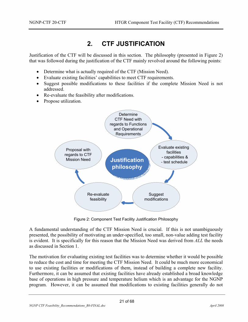
2. CTF JUSTIFICATION Justification of the CTF will be discussed in this section. The philosophy (presented in Figure 2) that was followed during the justification of the CTF mainly revolved around the following points:
� Determine what is actually required of the CTF (Mission Need). � Evaluate existing facilities’ capabilities to meet CTF requirements. � Suggest possible modifications to these facilities if the complete Mission Need is not
addressed. � Re-evaluate the feasibility after modifications. � Propose utilization.
Determine
CTF Need with regards to Functions
and Operational Requirements
Evaluate existing facilities
- capabilities &- test schedule
Suggest modifications
Re-evaluate feasibility
Proposal with regards to CTF Mission Need Justification
philosophy
Figure 2: Component Test Facility Justification Philosophy
A fundamental understanding of the CTF Mission Need is crucial. If this is not unambiguously presented, the possibility of motivating an under-specified, too small, non-value adding test facility is evident. It is specifically for this reason that the Mission Need was derived from ALL the needs as discussed in Section 1.
The motivation for evaluating existing test facilities was to determine whether it would be possible to reduce the cost and time for meeting the CTF Mission Need. It could be much more economical to use existing facilities or modifications of them, instead of building a complete new facility. Furthermore, it can be assumed that existing facilities have already established a broad knowledge base of operations in high pressure and temperature helium which is an advantage for the NGNP program. However, it can be assumed that modifications to existing facilities generally do not

NGNP-CTF 20-CTF HTGR Component Test Facility (CTF) Recommendations
22 of 68
NGNP CTF Feasibility_Recommendations_R0-FINAL.doc April 2008
deliver the required performance in terms of the Mission Need of the conceptualized facility. This is purely because existing facilities were typically designed and developed for another purpose and scope and more often than not experience has shown that the modification costs vs. outcome are not always justifiable. Therefore, the justification philosophy includes the re-evaluation of a facility’s capabilities after a proposed modification and how this addresses the CTF Mission Need. It is only hereafter that a proposal can be made to whether the CTF is justifiable in the greater NGNP life cycle need.
The CTF Mission Need from Section 1 can be elaborated further, and areas where such a facility will be applicable include:
� Qualification and testing of large scale components in a high temperature, high pressure environment such as the - Intermediate heat exchanger (IHX) - Ducting and insulation - Mixing chambers - Steam generator (SG) - High temperature valves - Specific application high temperature instrumentation - Industrial hydrogen components and - Helium circulators.
� Design code development Verification & Validation collaboration. � Materials development and qualification. � Manufacturer and supplier evaluation and development.
Other less tangible aspects1 justify the CTF due to the fact that:
� It will facilitate the role of Idaho National Laboratory (INL) in the coordination, consolidation and leading of the development of heat transfer and transport technologies to establish and advance the application of HTGR technology.
� It will ensure the availability of a facility to serve the development phases of the NGNP and beyond. The possible limited capacity and availability of other facilities (most of which are outside of the USA and supporting other projects) could adversely affect the NGNP schedule.
� It will improve the efficiency of technology development for the NGNP and follow-on technology upgrades.
� It provides a means for off-line trouble shooting of component and system problems and for the development of programs and processes to ultimately support a growing commercial HTGR fleet.
1 Some of these areas that are mentioned served as motivation for the CTF and can be found in [1]

NGNP-CTF 20-CTF HTGR Component Test Facility (CTF) Recommendations
23 of 68
NGNP CTF Feasibility_Recommendations_R0-FINAL.doc April 2008
� It provides a long-term US-based facility for continued development of advanced technologies to increase the capabilities and broaden the applications of the HTGR.
� It serves in the development of human capital and skills for the HTGR NGNP environment. � It provides insights in the identification of shortfalls in the CTF design that can be taken
into account in the NGNP design. � It provides an environment where Quality Assurance, safety and procurement systems can
be tested and verified and where shortfalls/enhancements can be identified. � It provides a means for the testing and evaluation of manufacturing technologies for large
scale manufacturing of First-of-a-Kind Engineering (FOAKE) systems and long lead time components.
� It will provide the opportunity to understand and test phenomena that prevail in transients of critical hot components at a CTF scale for both experimental results and V&V of codes.
� It will provide vast amounts of test data that will be beneficial for operation of the NGNP.
Before an evaluation of any facility could be done, it was important to define a measuring unit to which the facilities will be evaluated to. To define this measuring unit, the Functional and Operational Requirements (F&ORs) for the CTF needed to be laid down.
The process that was followed to determine F&ORs is discussed in the next section, after which the justification process continues with the evaluation of existing (or modified) facilities.

NGNP-CTF 20-CTF HTGR Component Test Facility (CTF) Recommendations
24 of 68
NGNP CTF Feasibility_Recommendations_R0-FINAL.doc April 2008
3. CTF FUNCTIONAL AND OPERATIONAL REQUIREMENTS Figure 3 illustrates the method that was followed in determining the F&ORs from the DDNs, TRLs and DRLs as presented in the DDNs Matrix in Appendix A. The sorted DDNs were further binned into main categories of components/systems to be tested. These are:
� Intermediate heat exchanger (IHX) � Mixing chambers � High temperature ducting and insulation � Steam generator (SG) � Helium circulator � Isolation valves � Auxiliary systems � Control and Instrumentation � Other heat exchanger (HX) equipment � General functions
The requirements from all three vendor groups’ DDNs were distilled into process parameters such as pressure, temperature, mass flow, energy required, etc. Some of the DDNs process parameter requirements were well defined in terms of units and magnitudes while others were very vague and mentioned needs in general and in very broad terms. These process parameters were sorted in matrix format with the aim to result in a Functional and Operational Requirements list that indicated the maximum values of the operational envelope of the CTF. These maximum values were useful to determine a first order sizing and conceptual layout of the CTF. This first order layout implied a facility that could possibly be equivalent in size to the NGNP itself due to requirements of full scale testing of some of the components. Also, at this stage in the process, it was not clear whether to provide for single component testing or assemblies of these components (such as the IHX). For obvious schedule and financial reasons, a facility of this scale is not feasible and a process of optimization was followed during which the categorized components/systems’ individual F&ORs were combined in such a fashion to define the tests that need to be performed in the CTF.

NGNP-CTF 20-CTF HTGR Component Test Facility (CTF) Recommendations
25 of 68
NGNP CTF Feasibility_Recommendations_R0-FINAL.doc April 2008
UUTs divided intoMain categories
IHX
Mixing chambers
High temperature Ducting & Insulation
Helium Circulator
Isolation valves
Auxiliary systems
Control & Instrumentation
Other HX testing equipment
General functions
XP T m QXP
DDNs – TRLs –DRLs
Justification philosophy
MissionNeed
Well defined requirements
including unambiguous
values
Vaguely defined requirements
stating a need in broad terms
T m Q
Functional & Operational Requirements
X(max)P(max) T(max) m(max) Q(max)
Functional and Operational Requirements list
Figure 3: Work flow diagram of the process that was followed to attain the Functional & Operational Requirements resulting in the Configuration Recommendation
The F&ORs for the tests in terms of energy balances, layouts and configurations were determined in the context of the Facility Philosophy (explained in Section 4) and resulted in three possible concepts. Concept 1 (which consists of three Technology Development Loops (TDLs) as well as a Component Qualification Loop (CQL) and full scale Circulator Test Loop (CTL)) was configured into fourteen (14) different setups to enable testing of all the required DDNs. Energy balances were performed on all the setups to determine the operational envelope of the system components. This resulted in a first order specification and sizing of the system elements. The same process was followed for Concept 2 where a total of three different setups, including energy balances were defined. The same process was not performed in as much detail for Concept 3 for reasons that will be discussed later in this section.

NGNP-CTF 20-CTF HTGR Component Test Facility (CTF) Recommendations
26 of 68
NGNP CTF Feasibility_Recommendations_R0-FINAL.doc April 2008
The Main categories into which the Units Under Test (UUTs), as listed in the DDNs, were divided are discussed in the next points with their individual F&ORs. A summary of a typical UUT, such as the IHX, together with Test Modes and a Test Specification is provided in Appendix G.

NGNP-CTF 20-CTF HTGR Component Test Facility (CTF) Recommendations
27 of 68
NGNP CTF Feasibility_Recommendations_R0-FINAL.doc April 2008
3.1 MAIN CATEGORIES OF UNITS UNDER TEST
3.1.1 IHX Component Tests
The CTF should have the flexibility to test a range of IHX designs, configurations, operating conditions and heat transport fluids. The heat transport fluids might have controlled levels of impurities in some tests. In the absence of a specific NGNP design, the options proposed by the three vendor teams were used as the basis for evaluating the potential range of development requirements.
Mockups or scaled representative IHX concepts are required to be tested in operating conditions comparable to anticipated NGNP conditions. The functionality for large scale testing at representative conditions should not be excluded.
The main tests to be conducted include: � IHX performance verification testing, which could serve as empirical validation for
thermal-hydraulic design methods and analysis. � Life prediction and durability testing to evaluate design and fabrication methods, as well as
data generated by material laboratories. Thermal-mechanical aspects of concepts should be evaluated during these tests, which typically include interface development.
� Seals tests on various sealing interfaces, as well as the influence on leak rates due to various process parameters.
� Flow induced vibration tests and tests on IHX configurations and its associated piping, together with frequency spectra and sound pressure levels caused by different flow velocities.
3.1.1.1 CTF IHX Operational Requirements: Westinghouse Vendor Team
The following provides a list of operational requirements for the CTF as imposed by IHX development and testing requirements from the Westinghouse Vendor Team.
� Primary helium inlet temperature of 950ºC (nominal) � Primary outlet temperature of 337ºC (nominal) � Secondary helium inlet temperature of 290ºC (nominal) � Secondary outlet temperature of 900ºC (nominal) � The CTF should provide for long-term testing, sufficient to provide confidence in the
operating life of the IHX components � IHX-A Primary Heat Transport System (PHTS) inlet pressure shall be 8,750 kPa � PHTS to Secondary Heat Transport System (SHTS) �P and interior to exterior �P near
zero (essentially pressure balanced at <200 kPa) � IHX-B SHTS inlet pressure shall be 9,100 kPa. � The working fluid in both the PHTS and the SHTS shall be helium, with controlled
impurity levels which are still To Be Defined (TBD).

NGNP-CTF 20-CTF HTGR Component Test Facility (CTF) Recommendations
28 of 68
NGNP CTF Feasibility_Recommendations_R0-FINAL.doc April 2008
� Pressure drop across primary side and also across secondary side of IHX shall be smaller than 1.23 percent of its respective inlet pressure (e.g. [Primary IHX-A inlet - Primary IHX-B outlet] < 108 kPa)
� A summary of the representative cores to be tested for both IHX A and B are provided in the following tables:
IHX-A (1 x Test Core) Requirements PRIMARY SECONDARY
m 1.15 [kg/s] (138 total cores) 1.15 [kg/s] (138 total cores) T_in 950 [°C] 710 [°C] T_out 760 [°C] 900 [°C] Pressure_in 8.750 [MPa] 9.011 [MPa] Delta T 190 [°C] Q 1.134 [MW] Dimensions: 1000 x 56 x 275 [mm]
IHX-B (1 x Test Core) Requirements
PRIMARY SECONDARY m 0.938 [kg/s] (170 total cores) 0.938 [kg/s] (170 total cores) T_in 760 [°C] 287 [°C] T_out 337 [°C] 710 [°C] Pressure_in 8.683 [MPa] 9.10 [MPa] Delta T 423 [°C] Q 2.058 [MW] Dimensions: 1000 x 56 x 420 [mm]
� The IHX test cores would need to be subjected to the transient testing to be defined � Cooling helium should be provided to the IHX test vessel if required by the unit under test
[TBD].
3.1.1.2 CTF IHX Operational Requirements: General Atomics Vendor Team
The following is a list of operational requirements for the CTF as imposed by IHX development and testing requirements from the General Atomics Vendor Team.
� It is necessary to confirm by experiment the flow distribution throughout the IHX (both primary and secondary inlets and outlets) accompanied by analytical evaluation.
� Data are needed to produce frequency spectra and sound pressure levels that may be generated by the IHX as a function of flow velocities.
� Physical and operational characteristics of insulation are required relative to thermal cycling, mechanical and acoustic vibrations, and effects of flow and thermal gradients.
� The CTF should be able to measure leak rates under operating conditions and should be configured in such a way to investigate the influence of various parameters in the leak rates.

NGNP-CTF 20-CTF HTGR Component Test Facility (CTF) Recommendations
29 of 68
NGNP CTF Feasibility_Recommendations_R0-FINAL.doc April 2008
� The flow induced excitation mechanisms of concern are turbulent buffeting, vortex shedding and fluid elastic instability.
3.1.1.3 CTF IHX Operational Requirements: AREVA Vendor Team
The following is a list of operational requirements for the CTF as imposed by tubular IHX development and testing requirements from the AREVA Vendor Team. These values represent the anticipated values for the full-scale heat exchanger and only representative parameters would need to be provided in the CTF.
Primary side (shell Side) � IHX inlet temperature: 900°C � IHX outlet temperature: 489.5°C � Primary side inlet pressure: 5 MPa � Pressure drop: 11.33 kPa � Fluid: Helium
Secondary side (tube side) � IHX inlet temperature: 449.1°C � IHX outlet temperature: 850°C � Secondary side inlet pressure: 5.46 MPa � Pressure drop: 260 kPa � Fluid: Helium – Nitrogen (He-N2) � The IHX test modules would need to be subjected to the following transients
- Cool-down transients of 300°C in 5 sec. - Heat-up transients of 300°C in 120 sec
� Representative geometry [TBD] � Testing of IHX concepts is proposed to be conducted in the following steps:
- Mock-up scaled versions to be tested in ~1 MW loop facility - Qualification tests of full-scale mock-up in ~10 MW loop facility
� All tests should be conducted with sufficient flow for representative flow distribution in headers, as well as providing all the representative conditions at the same time.
3.1.2 Mixing Chamber Test
The CTF should be capable of performing various predefined tests on representative helium mixing chamber designs and configurations.
The main tests to be conducted are:
� Performance verification test on a prototype mixing chamber. � Thermal cycling effects testing. � Nominal operating life of the mixing chamber [equivalent to NGNP plant life]. � Working fluid shall be helium. � Different size fixed orifice testing for mixing of gas.

NGNP-CTF 20-CTF HTGR Component Test Facility (CTF) Recommendations
30 of 68
NGNP CTF Feasibility_Recommendations_R0-FINAL.doc April 2008
3.1.2.1 CTF Mixing Chamber Operational Requirements: Westinghouse Vendor Team
The following is a list of operational requirements for the CTF as imposed by helium-mixing chamber development and testing requirements from the Westinghouse Vendor Team.
� Inlet pressure of 8.5 MPa for SHTS � Helium inlet temperature of 900°C � Process Coupling Heat Exchanger (PCHX)
- T-outlet: 660°C (Hydrogen Production System in operation) - T-outlet: 900°C (Hydrogen Production System not in operation)
� Mixing chamber outlet: 840°C � Total HTS flow: 159.6 kg/s
- Flow to PCHX: 39.9 kg/s - Flow to SG: 119.7 kg/s (NGNP required flow)
� Split of 75 percent hot gas (900°C) and 25 percent cold gas(660°C)
3.1.3 High Temperature Duct & Insulation Testing
The CTF should provide the capabilities to verify and experimentally validate the designs for high temperature ducts and insulation (HTD&I) which are to be used for fluid transport in both primary and secondary heat transfer loops. Experimental testing and validation will need to be performed on prototype samples and emphasis needs to be placed on long-term validations.
3.1.3.1 CTF HTD&I Operational Requirements: Westinghouse Vendor Team
The following is a list of operational requirements for high temperature duct and insulation design validation as required by the Westinghouse Vendor Team.
� PHTS ducts and insulation up to 950°C � SHTS ducts and insulation up to 900°C � Fluid: Helium � Piping prototypes need to be tested at full temperature and pressure (Pressures equal to
the requirements of the WEC IHX requirements need to be provided). � Flow rates: It is suggested to provide the same boundary velocity by means of an
annulus design. Final size and velocity TBD � Prototype tests include:
- Mechanical properties evaluation - Investigation of environmental effects on proposed designs - Long-term tests [TBD] for the validation of acceptability and continued
effectiveness (performance) of proposed designs under normal operating conditions.
3.1.3.2 CTF HTD&I Operational Requirements: AREVA Vendor Team
The following is a list of operational requirements for high temperature duct and insulation design validation as required by the AREVA Vendor Team.

NGNP-CTF 20-CTF HTGR Component Test Facility (CTF) Recommendations
31 of 68
NGNP CTF Feasibility_Recommendations_R0-FINAL.doc April 2008
� PHTS ducts and insulation up to 900°C � SHTS ducts and insulation up to 850°C � In order to address the risk of the high temperature ducts and insulation AREVA
proposed a qualifications process constituting of the following CTF related steps: - Subscale mock-up tests in helium of about 1 MW for validation purposes - Full scale mock-up test in ~10 MW test facilities.
� The tests should include: - Depressurization tests - Pressure drop, heat loss - Leak tightness of connections - Temperature measurement needs to be taken at various locations during operating
conditions.
3.1.4 Steam Generator Testing
The CTF should provide the capabilities to perform various tests on steam generator (SG) designs which include:
� Acoustic response testing under different flow conditions as well as flow induced vibrations due to various excitation mechanisms.
� Thermal and mechanical performance of steam generator related insulation. � Demonstration tests of certain design aspects in steam generators such as tube retention
and wear protection devices, and the non-helical transition tubes. These tests would typically be used for determining adequacy of existing designs, as well as evaluating new proposals.
� Seal-related tests in order to evaluate designs and validate performance-related criteria with varying parameters.
� Feed water related tests which include aspects such as orifice performance verifications, as well as design and manufacturing configurations.
� Steam generator instrumentation related mock-up tests need to be conducted. � Steam generator performance tests need to be conducted in order to evaluate the heat
transfer characteristics of certain regions.
3.1.4.1 CTF SG Operational Requirements: Westinghouse Vendor Team
The following is a list of operational requirements for the steam generator tests as required by the Westinghouse Vendor Team.
� Hot Side: - Fluid: Helium - Inlet pressure: 8.2 MPa - Pressure drop: ~ 0.1 MPa (NGNP requirement) - Inlet temperature: 900°C - Helium flow: 159.6 kg/s (NGNP requirement) - Outlet temperature: 272°C

NGNP-CTF 20-CTF HTGR Component Test Facility (CTF) Recommendations
32 of 68
NGNP CTF Feasibility_Recommendations_R0-FINAL.doc April 2008
- Design pressure: > 13.2 MPa
� Cold Side: - Fluid: water / steam - Feed water / steam flow: 206.3 kg/s - Feed water temperature: 219°C - Feed water pressure: 18.9 MPa - Steam pressure: 12.78 MPa
� Empirical data is needed to investigate the noise on large steam generator surfaces as a function of varying frequencies. Acoustical response of the tube bundle and cavity also need to be measured as a result of primary flow. Data to be generated include representative frequency spectra and sound pressure levels generated by the steam generator bundle as a function of velocities and geometry variations.
� Physical and operational characteristics of the insulation are to be verified as a result of: - Thermal cycling [cycles TBD] - Mechanical and acoustic vibrations - Flow and thermal gradients
� Accelerated wear tests to demonstrate existing tube-retention device designs.
� Operating requirements that influence the seal test are: - Performance verification and leak rates measurements under prototypical
conditions. - Influence of leak rates under differential pressures.
� Testing of non-helical portions of the tube bundle is needed to determine: - Spatial envelope - Characteristics of thermal movement - Interactions of tubes and supports to evaluate adequacy of clearances.
� Test should be conducted to accurately determine flow induced vibration characteristics of the helical tube bundle, lead-in/out tubes and transition tubes.
� Test data is needed to design and size orifices to be used in the individual tube circuits. Performance verification regarding erosion/corrosion resistances to be evaluated as well as fabrication and assembly performances. Data requirements include: - Pressure drop measurement - All data measurements in accordance with validation requirements
� Testing of steam generator mock-ups to confirm the design and assembly techniques of critical instrumentation. Ease of removal and replacement must be in accordance with requirements for experimental data and validation for non-safety related components.
NGNP-CTF 20-CTF HTGR Component Test Facility (CTF) Recommendations
33 of 68
NGNP CTF Feasibility_Recommendations_R0-FINAL.doc April 2008
3.1.4.2 CTF SG Operational Requirements: General Atomics Vendor Team
Data required once the design has developed further and materials have been selected.
3.1.5 Helium Circulator
The CTF should provide for full scale integrated tests of various circulator configurations which could assist in the verification of circulator component designs and adequacy of support systems. Typical tests will include:
� Circulator design verification tests � Circulator performance empirical verification � Circulator control system testing.
3.1.5.1 CTF Circulator Operational Requirements: Westinghouse Vendor Team
The following is a list of operational requirements for the CTF as imposed by helium circulator development and testing requirements from the Westinghouse Vendor Team:
� Primary helium loop pressure of 9MPa � Primary inlet temperature of 350°C exit conditions � Secondary helium loop pressure of 9MPa � NGNP Design: 10.8 MW Circulator
3.1.5.2 CTF Circulator Operational Requirements: General Atomics Vendor Team
The following is a list of operational requirements for the CTF as imposed by helium circulator development and testing requirements from the General Atomics Vendor Team.
� Primary helium circulator � Secondary helium circulator (Secondary circulator DDNs are covered by primary
helium circulator DDNs due to design similarity) � Shutdown cooling circulator � Primary and secondary 5 MPa.
3.1.5.3 CTF Circulator Operational Requirements: AREVA Vendor Team
The following is a list of operational requirements for the CTF as imposed by helium circulator development and testing requirements from the AREVA Vendor Team.
� Scale: Full scale recommended � NGNP proposal
- 3 x 5 MW circulators & 1 x 1.5 MW circulator - At full power required, the circulator should run at maximum of 90 percent
� Primary and secondary pressure of 5MPa.

NGNP-CTF 20-CTF HTGR Component Test Facility (CTF) Recommendations
34 of 68
NGNP CTF Feasibility_Recommendations_R0-FINAL.doc April 2008
3.1.6 Valves Testing
The CTF should provide the capabilities to do performance and structural verification on high temperature valves for maintenance and/or isolation, albeit design requirements are still TBD.
3.1.6.1 CTF Valves Operational Requirements: General Atomics Vendor Team
The following is a list of operational requirements as obtained from the General Atomics PCDR: � CTF should provide large scale facilities for valve testing at 950°C in representative
primary loop environment. � Tests to be used for component qualification
3.1.7 Auxiliary Systems
The CTF should provide a complete array of auxiliary systems in support of the tests to be conducted. These auxiliary systems should include, but are not limited to the following:
� Helium purification system � Helium inventory control system � Heat rejection systems (typically air cooled condensers instrumented to enable full
energy balances) � Control instrumentation air system
3.1.8 Control & Instrumentation
The CTF must be used for instrumentation and control philosophy development as well as adequacy verification for certain applications.
3.1.8.1 CTF C&I Operational Requirements: General Atomics Vendor Team
Typical requirements for the CTF regarding instrumentation include the following: � Capabilities to measure and verify helium mass flow measurements � Verify conduction cool down temperature monitoring instrumentation � All instrumentation to be used for verification and validation purposes
3.1.9 Other Helium Heat Exchanger Testing Requirements
The CTF should be capable of performing various predefined tests on representative supporting component designs and configurations, including the shutdown heat exchanger. The main tests to be conducted in support of the shutdown heat exchanger are:
� Insulation verification tests � Vibrational fretting wear and sliding wear of tube restraint � Devices for bare tubes � Instrumentation attachment test � Bare tubes inspection methods and equipment � Shroud seal test � Acoustical response of the helical bare tube bundle

NGNP-CTF 20-CTF HTGR Component Test Facility (CTF) Recommendations
35 of 68
NGNP CTF Feasibility_Recommendations_R0-FINAL.doc April 2008
� Inlet flow and temperature distribution test � Tube bundle local heat transfer and flow resistance characteristics
3.1.9.1 CTF Operational Requirements: General Atomics Vendor Team
All other heat exchanger test requirements relate to DDNs as determined by the General Atomics Vendor Team. Detailed requirements are TBD once the design is further developed.
3.1.10 General Functions
The following is a list of general functions that should be addressed by the CTF. � The CTF should provide data and measurements that could be utilized for verification
and validation purposes of thermal-fluid related software. � The CTF should also be used for qualifications control as well associated program
requirements development. � Control room human factors are also envisaged to be tested and developed using the
CTF. � Specific hydrogen production testing is not defined yet but should be included in the
future.
The F&ORs for the CTF have been determined in this section and provide a set of requirements that existing facilities can be measured against. The next section describes the South African facilities and their ability to meet the requirements of the CTF.

NGNP-CTF 20-CTF HTGR Component Test Facility (CTF) Recommendations
36 of 68
NGNP CTF Feasibility_Recommendations_R0-FINAL.doc April 2008
3.2 SOUTH AFRICAN TEST FACILITIES
The PBMR facilities were identified and used in the justification of the CTF primarily because they have the ability to test under high temperature and pressure helium conditions. Other facilities located or planned elsewhere in the world which are listed in [1] were excluded in this evaluation due to time and resource constraints. However, a literature study on some German facilities (Appendix C) was conducted to determine what was done on other typical test facilities with similar mission needs. The literature study also served as guidance to establish the Envelope Philosophy (e.g., full scale testing vs. laboratory scale testing, etc.) that was followed in the justification of the CTF.
The South African PBMR test facilities were designed, built and operated specifically for the technology development of the PBMR Demonstration Power Plant (PBMR DPP). The following facilities were reviewed:
� The Helium Test Facility (HTF) � The Heat Transfer Test Facility (HTTF), which consists of two units:
- The High Pressure Test Unit (HPTU) and - The High Temperature Test Unit (HTTU)
� The Pebble Bed Micro Model (PBMM).
(Refer to Appendix B for detailed descriptions of these facilities.)
The assessment of the facilities concurred with the justification philosophy (presented in Section 2) in terms of the evaluation with regard to their capabilities, test schedule, possible modifications, current configuration and ability to address the CTF Mission Need. The outcome of the assessment is briefly presented in the following sections.
3.2.1 The Helium Test Facility
The Helium Test Facility (HTF) was mandated to do design/development/functional/integrated and performance testing on the PBMR Main Support Systems (MSS) up to delivery of the MSS to the first demonstration plant. The main focus of the HTF hereafter is full scale, non nuclear tests on the Fuel Handling System (FHS), Reactivity Control System (RCS) and Reserve Shutdown System (RSS). These systems are termed Units Under Test (UUTs).

NGNP-CTF 20-CTF HTGR Component Test Facility (CTF) Recommendations
37 of 68
NGNP CTF Feasibility_Recommendations_R0-FINAL.doc April 2008
Figure 4: High level process flow diagram of the Helium Test Facility Main Loop
3.2.1.1 Capabilities
The HTF supports the development, verification and non-nuclear testing of critical prototype components of the PBMR MSS. It provides the capability to test components and sub-assemblies in a high-temperature and high-pressure helium environment that is similar to the operating conditions expected for the PBMR DPP. The operational envelope of the HTF is provided in Table 1 and Figure 5. From this table, it is evident that the maximum usable flow rate and temperature are on the order of 1kg/s and 900�C respectively. (NOTE: These conditions cannot be attained simultaneously; see Appendix B for more details.)

NG
NP-
CTF
20-
CTF
H
TGR
Com
pone
nt T
est F
acili
ty (C
TF) R
ecom
men
datio
ns
38
of 6
8 N
GN
P C
TF F
easi
bilit
y_Re
com
men
datio
ns_R
0-FI
NAL
.doc
Apri
l 200
8
Tabl
e 1:
Hel
ium
Tes
t Fac
ility
(HTF
) Ope
ratio
nal C
ondi
tions
N
o.D
escr
iptio
n
Pres
sure
[MPa
][k
g/s]
[°C
][k
g/s]
[°C
][k
g/s]
[°C
][k
g/s]
[°C
][k
g/s]
[°C
][k
g/s]
[°C
]kg
/s[°
C]
Dat
e
1FH
SS
@ 1
MPa
Lin
e D
, T =
280
°C (v
ia F
HS
sys
tem
)X
1-
-0.
051
280
--
--
--
--
0.05
128
0[T
BD
]
2FH
SS
@ 1
MPa
Lin
e G
, T =
200
- 25
0°C
(via
equ
alis
atio
n lin
e)X
1-
--
--
--
--
-0.
0325
00.
0325
0[T
BD
]
3FH
SS
@ 1
MPa
Lin
e G
, T =
280
°C (v
ia F
HS
syst
em)
X1
--
--
--
--
--
0.13
280
0.13
280
[TB
D]
4R
SS @
2.2
MPa
& T
_max
< 2
50°C
X2.
20.
0525
00.
0560
0.05
600.
1510
00.
0550
--
0.05
250
[TB
D]
5R
SS @
6.5
MPa
& T
_max
< 3
00°C
X6.
50.
0530
00.
0510
00.
0510
00.
0310
00.
0550
--
0.05
300
[TB
D]
6R
SS @
6.5
MPa
& T
_max
< 6
00°C
X6.
50.
0550
00.
0510
00.
0510
00.
0310
00.
0550
--
0.05
500
[TB
D]
7R
SS @
9.0
MPa
& T
_max
< 3
00°C
(SAS
tran
spor
t)X
90.
0530
00.
0528
00.
0528
00.
415
00.
0550
--
0.05
300
[TB
D]
8R
SS @
9.0
Mpa
& T
_max
< 6
00°C
(SAS
tran
spor
t)X
90.
0558
00.
0528
00.
0528
00.
415
00.
0550
--
0.05
580
[TB
D]
9R
SS @
9.0
Mpa
& T
_max
< 9
00°C
(SAS
tran
spor
t)X
90.
0575
00.
0528
00.
0528
00.
415
00.
0550
--
0.05
750
[TB
D]
10R
SS @
9.0
Mpa
& T
_max
< 6
00°C
(Man
ifold
D fo
r low
er R
SS
vess
el
cond
ition
ing
at 3
50°C
)X
90.
0558
00.
135
00
-0
-0.
0550
--
0.05
580
[TB
D]
11R
SS @
9.0
Mpa
& T
_max
< 9
00°C
(Man
ifold
D fo
r low
er R
SS v
esse
l co
nditi
onin
g at
350
°C)
X9
0.05
750
0.1
350
0-
0-
0.05
50-
-0.
0575
0[T
BD
]
12R
CS
@ 9
.0 M
Pa &
T_m
ax <
300
°CX
90.
230
00.
0628
00.
0528
00.
0512
00.
0550
--
0.2
300
[TB
D]
13R
CS
@ 9
.0 M
Pa &
T_m
ax <
600
°CX
90.
258
00.
0628
00.
0528
00.
0520
00.
0550
--
0.2
580
[TB
D]
14R
CS
@ 9
.0 M
Pa &
T_m
ax <
600
°CX
90.
0590
00.
0528
00.
0528
00.
415
00.
0550
--
0.05
900
[TB
D]
15R
CS
@ 9
.0 M
Pa &
T_m
ax <
300
°C (N
o m
anifo
ld C
flow
)X
90
-0.
0628
00.
0518
00.
0512
00.
0550
--
0.06
280
[TB
D]
16R
CS
@ 9
.0 M
Pa &
T_m
ax 6
00°C
(No
man
ifold
C fl
ow)
X9
0-
0.06
350
0.05
180
0.05
120
0.05
50-
-0.
0635
0[T
BD
]
17R
CS
@ 9
.0 M
Pa &
T_m
ax <
600
°C (N
o m
anifo
ld A
& E
flow
)X
90.
2258
00.
0635
00
-0
-0.
0550
--
0.22
580
[TB
D]
18R
CS
@ 9
.0 M
Pa &
T_m
ax <
900
°C (N
o m
anifo
ld A
& E
flow
)X
90.
2290
00.
0635
00
-0
-0.
0550
--
0.22
900
[TB
D]
19C
ombi
ned
RC
S &
RS
S @
9.0
MPa
& T
_max
< 3
00°C
X9
0.25
300
0.11
0.1
0.9
280
0.35
120
0.9
50-
-0.
2530
0[T
BD
]
20C
ombi
ned
RC
S &
RS
S @
9.0
MPa
& T
_max
< 6
00°C
X9
0.25
580
0.11
280
0.9
280
0.35
120
0.1
50-
-0.
2558
0[T
BD
]
21FH
SS
@ 9
.0 M
Pa, T
=280
°C (v
ia e
qual
isat
ion
line)
X9
--
--
--
--
--
0.6
280
-0
-
22FH
SS
@ 9
.0 M
Pa, T
=280
°C (v
ia F
HS
syst
em)
X9
--
--
--
--
--
0.58
280
-0
-
Max
imum
Con
ditio
ns9
0.25
900
0.11
350
0.9
280
0.4
200
0.9
500.
628
0
Not
es1
Tem
pera
ture
mea
sure
d at
man
ifold
C2
Tem
pera
ture
at n
ozzl
e of
RSS
test
set
-up
vess
el (N
6)3
Man
ifold
D u
sed
for c
ondi
tioni
ng o
f RSS
ves
sel b
otto
m4
Tem
pera
ture
at n
ozzl
e of
RSS
test
set
-up
vess
el (N
8)5
Tem
pera
ture
at n
ozzl
e of
RSC
test
set
-up
vess
el (N
8)6
Tem
pera
ture
at n
ozzl
e of
RSS
(N6)
and
RC
S (N
8) te
st s
et-u
p ve
ssel
s
7Te
mpe
ratu
re w
ithin
bor
ing
(to
be a
chiv
ed w
ith h
eate
r H1,
H2
and
H5
or
inte
rnal
RS
S he
atin
g)8
Bor
ing
tem
pera
ture
abo
ve 5
80 to
be
achi
eved
with
H6
Phase I
Phase II
Phase III
Lab
Avai
libilt
yE
F
Man
ifold
Line
GC
DA

NGNP-CTF 20-CTF HTGR Component Test Facility (CTF) Recommendations
39 of 68
NGNP CTF Feasibility_Recommendations_R0-FINAL.doc April 2008
Figure 5: Helium Test Facility (HTF) operational envelope (dark blue area) compared against a facility that will typically address the CTF F&ORs (grey area)
3.2.1.2 Test Schedule
Currently, the HTF team works closely with PBMR Testing, Qualification and Commissioning (TQC) to develop and implement test and qualification strategies for the development and testing of the previously mentioned systems. On this basis, a total of 275 tests were defined and need to be completed on a priority basis in support of these systems. Based on what is contained in the qualification strategies, the HTF management estimated the number of tests that need to be completed per annum to allow designers to deliver these PBMR DPP systems on time. Currently 25 critical design/development tests have been scheduled for completion during 2008, with the rest of the 275 scheduled for the following year and in the future. The latest forecast indicated that the HTF will be committed to PBMR DPP MSS tests until at least 2012. This schedule takes into account the current availability of resources and plant capability.
3.2.1.3 Possible Modifications
In essence, it must be understood that the HTF is actually a “cold” system with locally heated hot spots for testing the three UUTs. Essentially the HTF consists of a main loop with heaters, a helium circulator, coolers, etc. and three UUTs coupled thereto (refer to Figure 4). It is therefore not a facility that can easily be modified to suit the CTF Mission Need. However, a HTF Laboratory is being designed where some lab-scale tests can be conducted on components such as valves. A proposal for a secondary loop in the laboratory area with an operating envelope of ±1 kg/s at 9 MPa and localized heating to ~950 �C can be found in Appendix B and is depicted in Figure 6.

NGNP-CTF 20-CTF HTGR Component Test Facility (CTF) Recommendations
40 of 68
NGNP CTF Feasibility_Recommendations_R0-FINAL.doc April 2008
FRO
M H
ICB
S
TO H
ICB
S
Primary Loop:1. Fluid: Helium 2. Pressure 9 Mpa3.
Figure 6: High level process flow diagram of the possible modifications to the HTF Laboratory
3.2.1.4 Current Configuration
The HTF, as a complete facility, is currently not configured to support major changes. The only foreseeable changes are the addition of the HTF Laboratory and possible increases in temperature in the localized heating in the UUTs to represent the NGNP conditions.
3.2.1.5 Ability To Address CTF Mission Need
When the HTF capability envelope is compared to the CTF Envelope Philosophy and F&ORs, it is found the HTF cannot address the requirements due to capability constraints on components, current and future test schedules and physical space constraints. Due to established test schedules, this facility will not be available for use within the required timeframe to achieve the 2018 NGNP startup.
The HTF cannot accommodate full scale testing of HTS components, but rather specialized testing of materials or scaled components at diluted requirements when compared with the NGNP F&ORs.

NGNP-CTF 20-CTF HTGR Component Test Facility (CTF) Recommendations
41 of 68
NGNP CTF Feasibility_Recommendations_R0-FINAL.doc April 2008
An important aspect that also came out of the investigation is the fact that nowhere in the DDNs were the PBMR DPP related tests that are currently underway at the HTF mentioned. It is evident that the assumption was made that these tests do not need further investigation by the WEC NGNP team due to the fact that PBMR was already committed to obtaining the results for PBMR DPP purposes. These results could, in the future, be offered in kind, but will require further investigation and negotiations among the relevant parties.
It must also be noted that the PBMR DPP and NGNP have slightly different operating conditions in terms of inlet and outlet temperatures. The PBMR DPP has a core outlet temperature of 900�C compared to the 950�C of the NGNP. This would imply that the HTF test conditions are only set up to reach NGNP requirements that fall within the range of the PBMR DPP. It is proposed that a separate study be done on exactly what modifications need to be made, if any, to the HTF to test and verify that the MSS components that are under test will suffice for the NGNP reactor as well.
3.2.2 The Pebble Bed Micro Model
The purpose of the Pebble Bed Micro Model (PBMM) was to demonstrate the concept and controllability of the PBMR three-shaft recuperated closed Brayton Cycle. The PBMM was also utilized to demonstrate the Flownex computer code’s ability to accurately predict the dynamic behavior of the system. The operational envelope of the PBMM is found in Table 2. From this table it is evident that the maximum usable flow rate and temperature is in the order of 2kg/s and 700�C, respectively, with Nitrogen as the working fluid. (NOTE: These conditions cannot be attained simultaneously; see Appendix B for more details.)
3.2.2.1 Capabilities
Table 2: Pebble Bed Micro Model Operational Conditions
Variable Unit Min Max
System Pressure MPa (abs) 0 0.9
System Mass Flow Rate kg/s 0 2 System Heater Power kW 0 350 Heater Temperature °C 0 700 Fluid --- Nitrogen Nitrogen
3.2.2.2 Test Schedule
The PBMM is currently not in use.
3.2.2.3 Possible Modifications And Current Configuration
Extensive modifications are needed to change the current facility for use as a component test facility or laboratory. The major changes will include a blower, pipe work, a new control system and instrumentation. The use of helium in the facility must be investigated further as sealing of the vessel will be of concern.

NGNP-CTF 20-CTF HTGR Component Test Facility (CTF) Recommendations
42 of 68
NGNP CTF Feasibility_Recommendations_R0-FINAL.doc April 2008
3.2.2.4 Ability To Address CTF Mission Need
When the PBMM capability envelope is compared to the CTF Envelope Philosophy and F&ORs, it is found the PBMM cannot address the requirements. It is not foreseen that the PBMM will suffice for use as a CTF in terms of the CTF Envelope Philosophy.
3.2.3 The Heat Transfer Test Facility The Heat Transfer Test Facility (HTTF) consists of two clearly distinguishable test units, namely the High Temperature Test Unit (HTTU) and the High Pressure Test Unit (HPTU). The purpose of the facility is twofold namely:
� To validate the correlations that are currently used to model the relevant heat transfer and fluid flow phenomena required for the integrated simulation of the pebble bed core, via a comprehensive set of separate effects tests.
� To generate results that may be used to validate the different simulation methodologies applied in the integrated models that represent the entire pebble bed core, via a comprehensive set of integrated effects tests.
3.2.3.1 High Temperature Test Unit
HTTU Capabilities
The HTTU is an integrated effects test facility that represents a section of the pebble bed reactor. The HTTU pebble annulus is the same width and geometrically similar to the actual PBMR reactor core and it will be used to measure the heat transfer characteristics of the pebble bed as a whole. Some of the tests that will be conducted with the HTTU will be used to validate correlations currently employed by PBMR for the determination of the pebble-to-pebble effective conductivity, pebble-to-reflector conductivity and temperature profiles through the core for different gas flow rates. These tests include steady-state and transient experiments with nitrogen and helium under different conditions. The high temperature pebble bed core or test section forms the heart of the HTTU plant. The test section contains about 28,000 graphite spheres of size similar to that of the PBMR fuel spheres. The operational envelope of the HTTU is found in Table 3 and Figure 7. From this table it is evident that the maximum usable flow rate and temperature are on the order of 4kg/s and 1200�C in the flow configuration and 1600�C in the near vacuum and natural convection configurations. The fluids that can be used in the HTTU are Helium (Natural Convection) and Nitrogen (Natural and Forced Convection) at pressures ranging from 10-100kPa (abs).
NOTE: These conditions cannot be attained simultaneously (see Appendix B for more details).
Table 3: High Temperature Test Unit (HTTU) Operational Conditions
Variable Unit Min MaxSystem Pressure kPa (abs) 10 100 System Mass Flow Rate - Nitrogen kg/s 0 0.5 System Heater Power kW 0 500 Heater Temperature ºC Ambient 1600 Heat Exchanger Power kW 0 157

NGNP-CTF 20-CTF HTGR Component Test Facility (CTF) Recommendations
43 of 68
NGNP CTF Feasibility_Recommendations_R0-FINAL.doc April 2008
Fluid Helium & Nitrogen
Figure 7: High Temperature Test Unit (HTTU) operational envelope (dark blue area) compared against a facility that will typically adress the CTF F&ORs (grey area)
HTTU Test Schedule The HTTU is currently utilized for PBMR tests and it is foreseen that it will be available in 2010 for other work.
HTTU Possible Modifications And Current Configuration It is not foreseen that modification to the HTTU configuration can be made to further address the CTF Mission Need. However, the results obtained from the HTTU will be relevant to the NGNP as it forms the basis for the PBMR design and will be used to V&V the correlation used in the simulation of the PBMR reactor.
HTTU Ability To Address CTF Mission Need When the HTTU capability envelope is compared to the CTF Envelope Philosophy and F&ORs, it is found the HTTU cannot address the requirements due to its inability to meet operational requirements. The tests that are currently being conducted could possibly be presented in-kind from PBMR to contribute to the NGNP’s success and vice-versa.

NGNP-CTF 20-CTF HTGR Component Test Facility (CTF) Recommendations
44 of 68
NGNP CTF Feasibility_Recommendations_R0-FINAL.doc April 2008
3.2.3.2 High Pressure Test Unit
HPTU Capabilities The HPTU operates at a system pressure of 5.0 MPa and a temperature of 75°C, using nitrogen as the working fluid. The HPTU consists of a number of test sections, each evaluating different parameters and reactor phenomena.
The aim of the HPTU is to validate the correlations that are used for different heat transfer and fluid flow phenomena through comprehensive Separate Effects Tests (SET), and to validate the different simulation methodologies used in the integrated models through comprehensive Integrated Effects Tests (IET). It should be noted that the HPTU is not an exact scale model of the actual reactor core or any other reactor structures. It is merely an assortment of representative sections of a pebble bed core, suitable for conducting SET and IET.
The operational envelope of the HPTU is found in Table 4 and Figure 8. From Table 4, it is evident that the maximum usable flow rate is on the order of 2.9kg/s. The fluid that is used in the HPTU is Nitrogen at pressures ranging from 100 to 5,000kPa (abs).
Table 4: High Pressure Test Unit (HPTU) Operational Conditions
Variable Unit Min MaxCompletiondate
System Pressure kPa 100 5000 Jan ‘08 System Mass Flow Rate kg/s 0.01117 2.888 Jan ‘08 Braiding Mass Flow Rate kg/s 0.001532 0.12480 Jan ‘08 System Heater Power kW 0.03491 9.668 Jan ‘08 Braiding Heater Power kW 0.127 5.481 Jan ‘08 Heat Exchanger Power kW 0.04507 0.04507 Jan ‘08
Figure 8: High Pressure Test Unit (HPTU) operational envelope (dark blue area) compared against a facility that will typically adress the CTF F&ORs (grey area).
NGNP-CTF 20-CTF HTGR Component Test Facility (CTF) Recommendations
45 of 68
NGNP CTF Feasibility_Recommendations_R0-FINAL.doc April 2008
HPTU Test schedule The HPTU is fully operational and at the end of its testing phase. The tests for the PBMR were completed at the end of February 2008.
HPTU Possible Modifications and Current Configuration Extensive modifications (localized heating and cooling) are required to reach high temperatures (T>900 ºC) and that at only 5.0 MPa. It is therefore not foreseen that modification to the HTTU configuration can be made to further address the CTF Mission Need. However, the results obtained from the HPTU will be relevant to the NGNP.
HPTU Ability to Address CTF Mission Need When the HPTU capability envelope is compared to the CTF Envelope Philosophy and F&ORs, it is found the HPTU cannot address the requirements due to the fact that it was designed to be a high pressure, low temperature and flow rate, Nitrogen operated facility. The tests that are currently being conducted could possibly be presented in-kind from PBMR to contribute to the NGNP’s success and vice-versa.
3.2.4 Justification Conclusion
In conclusion, it can be said that after employing the Justification Philosophy to evaluate the South Africa test installations, these facilities do not meet the Mission Statement, Functional and Operational Requirements or Envelope Philosophy and will, therefore, not be suitable as Component Test Facility candidates.
This implies that a completely new facility must be designed and constructed to serve the life cycle requirements of the NGNP. The new facility must be specified in terms of what the F&ORs dictate to result in a solution that will meet the imposed CTF Mission.
The following section presents the recommendations for three concepts of the CTF that should meet the requirements listed in the preceding sections.

NGNP-CTF 20-CTF HTGR Component Test Facility (CTF) Recommendations
46 of 68
NGNP CTF Feasibility_Recommendations_R0-FINAL.doc April 2008
4. CTF CONFIGURATION RECOMMENDATIONS Using the DDNs, together with additional requirements, a Functional and Operational Requirements List was created, which basically dictated a number of different test configurations (refer to Figure 9 for the process that was followed). The different concepts were evaluated and will be discussed in this section. Detail descriptions on all the concepts can be found in Appendix F.
XP T m QXP
Well defined requirements
including unambiguous
values
Vaguely defined requirements
stating a need in broad terms
T m Q
Functional & Operational Requirements Definitions of tests to be performed in CTF to address all DDNs (Matrix format )
X(max)P(max) T(max) m(max) Q(max)
Functional and Operational Requirements list
Con
cept
1C
once
pt 2
Con
cept
3
Configuration Recommendations
IHX Vessel
Test Station:
Recuperator
Recuperator
Cooling gas
IHX C& I
Dust Generator
Test Station Ins trumentation
Requirements: Tes ting of- Hot c ircu i t p ip ing- Iso lation valves- Mix ing chambers- IHX LS
Test Station Vess el Primary Loop : Helium
Secondary Loop : Helium
IHX Vessel
Recuperator
Recuperator
Cool ing gas
IHX C& I
Primary Loop : Helium
Secondary Loop : He-N2 / Other fluids
Test S tation
Recuperator
Cooling gas
C&I
Primary Loop : Helium
Small loop #1Small loop #2
Small loop #3
LOOP #1
LOOP #2
LOOP #3
LOOP #1
LOOP #2
LOOP #3
Primary Loop : HeliumLarge Loop
From N
GN
P
To Large Loop
To Large Loop
From Large Loop
From Large Loop
From Large Loop
Test v ess el for large c om ponent
qual ification
TO N
GN
P
Recuperator
Large s cale IHX testing
To Large Loop
Steam GeneratorVessel
Feed P re -heater
A ir Cooled Condenser s
Circulator Test loop
From H
ICS
From H
PS
Fil ter sta tion
H 1.1
H 3.1
H 2.1
Recuperator
A ir Cooled Condensers
C 1.1
RX 1.1
TS 1.1DG 1.1 IHX 1.1 FS 1.1
CL 1.1
TS 1.2
Heater
RX 1.2
C 1.2
RX 3.1
C 3.1
CL 1.2
CL 3.1
TS 3.1
C 2.1
C 2.2
CL 2.1
IHX 2.1
CL 2.2
RX 2.1
RX 2.2
IHX 4.1
RX 4.2RX 4.3
CL 4.2
SG 4.1CL 4.1
C 5.1
CL 5.1
LP Tank
LP 2.2Auxiliary Systems Control & Instrumentation
? HICS? LP vent vessel? HPS
? Process Control
? Water treatment plant
? Compressed air systems
? Test specific instrumentation
? V & V instrumentation
NOTE: E ach Tes t Loop wi ll have i ts own set o f aux il ia ry ss ystem s, no shearing of
support sys tems
NOTE: Each Test loop wil l hav e own set o f control & instrumentation sys tems , no
s hearing of support sy stems
AC 1.1
Heat transfer component / Recuperator / IHX
Legend
Circulator
Cooler HX
Closed ci rcu it cool ing tower / a i r cooled condens er
Pressure v ess el / Tes t vessel
Elec tric res is tance heating
Ai r Cooler
Concept 1: Basic Layout
IHX Test Core
IHX Vessel
IHX Spool piece
IHX Test Core
IHX Vessel
IHX Spool piece
Test Station
Test Station
Feed Pre-heater
Air Cooled Condensers
Full scale Circulator test loop
From H
ICS
From H
PS
Large scale CTF loop
Auxiliary Systems Control & Instrumentation
? HICS? LP vent vessel? HPS
? Process Control
? Water treatment plant
? Compressed air systems
? Test specific instrumentation
? V & V instrumentation
NOTE: Each Test Loop will have its own set of auxiliary ssystems, no shearing of
support systems
NOTE: Each Test loop will have own set of control & instrumentation systems, no
shearing of support systems
Legend
Circulator
Cooler HX
Closed circuit cooling tower / air cooled
condenser
Heat transfer component /
Recuperator / IHX
Pressure vessel / Test vessel
Electric resistance heating
Pumps
Steam generator
Test Stations
Heater
Recuperator
Heater
Circulators
Circulators
Cooler
Cooler
Circulator under test
Cooler
Concept 2: Basic Layout
Figure 9: Work flow diagram of the process that was followed to recommend configurations of the CTF that will address all Mission Needs.
From the different F&ORs in the previous section, it is clear that the capability to test a vast array of components and configurations needs to be provided for in the recommended facility concepts. In addition to these verification tests, it is also required to perform long-term life prediction and durability tests on either representative mock-up models or larger scaled components. Keeping this in mind, a Facility Philosophy was derived to enable the proposal for such a facility with different concepts.

NGNP-CTF 20-CTF HTGR Component Test Facility (CTF) Recommendations
47 of 68
NGNP CTF Feasibility_Recommendations_R0-FINAL.doc April 2008
The Facility Philosophy dictates that recommended concepts of the facility:
� Should have the capability of performing numerous tests at the same time. This is needed to address the various long-term testing requirements from different vendors.
� Need to accommodate further development work in terms of coupling commercial process demonstrations via high temperature heat exchangers.
� Should provide test capability for mock-up / scaled versions of certain components under test, while also allowing for full scale testing on circulators.
� Need to provide the capability to investigate different fluids (gases) in secondary loops. � Should provide sufficient auxiliary systems to perform tests and become familiar with
the working of these systems. � Need to provide an environment where control philosophies can be tested. � Need to provide an environment where development work can be performed on certain
instrumentation. � Should strive to utilize components that are one order more reliable than the
components under test, typically commercial-off-the-shelf (COTS) items. � An additional requirement is that the complete facility should be constructed and
instrumented with Verification and Validation (V&V) in mind. � Endeavor to possibly facilitate connection to a Nuclear Heat Source (NHS). If the
connection to a NHS is required, the facility would need to be designed and built according to ASME III which will lead to a steep increase in cost.
Three different concepts are proposed in this report, based on the Facility Philosophy, above. Each of these concepts will be described with reference to its layout, the enveloping values as determined from the different test configurations and some additional considerations.
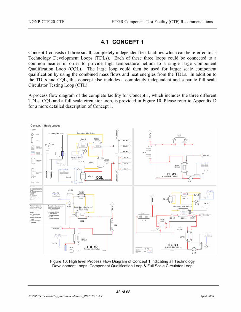
NGNP-CTF 20-CTF HTGR Component Test Facility (CTF) Recommendations
48 of 68
NGNP CTF Feasibility_Recommendations_R0-FINAL.doc April 2008
4.1 CONCEPT 1
Concept 1 consists of three small, completely independent test facilities which can be referred to as Technology Development Loops (TDLs). Each of these three loops could be connected to a common header in order to provide high temperature helium to a single large Component Qualification Loop (CQL). The large loop could then be used for larger scale component qualification by using the combined mass flows and heat energies from the TDLs. In addition to the TDLs and CQL, this concept also includes a completely independent and separate full scale Circulator Testing Loop (CTL).
A process flow diagram of the complete facility for Concept 1, which includes the three different TDLs, CQL and a full scale circulator loop, is provided in Figure 10. Please refer to Appendix D for a more detailed description of Concept 1.
IHX Vessel
Test Station:
Recuperator
Recuperator
Cooling gas
IHX C&I
Dust Generator
Test Station Instrumentation
Requirements: Testing of- Hot circuit piping- Isolation valves- Mixing chambers- IHX LS
Test Station Vessel Primary side : Helium
Secondary side : Helium
IHX Vessel
Recuperator
Recuperator
Cooling gas
IHX C&I
Primary side : Helium
Secondary side : He-N2 / Other fluids
Test Station
Recuperator
Cooling gas
C&I
Primary side : Helium
TDL #1TDL #2
TDL #3
TDL #1
TDL #2
TDL #3
TDL #1
TDL #2
TDL #3
Primary side : HeliumCQL
From N
GN
P
To CQ
L
To CQ
L
From CQL
From CQL
From CQL
Test vessel for large component
qualification
TO N
GN
P
Recuperator
Large scale IHX testing
To CQ
L
Steam GeneratorVessel
Feed Pre-heater
Air Cooled Condensers
Circulator Test loop
From H
ICS
From H
PS
Filter station
H 1.1
H 3.1
H 2.1
Recuperator
Air Cooled Condensers
C 1.1
RX 1.1
TS 1.1DG 1.1 IHX 1.1 FS 1.1
CL 1.1
TS 1.2
Heater
RX 1.2
C 1.2
RX 3.1
C 3.1
CL 1.2
CL 3.1
TS 3.1
C 2.1
C 2.2
CL 2.1
IHX 2.1
CL 2.2
RX 2.1
RX 2.2
IHX 4.1
RX 4.2RX 4.3
CL 4.2
SG 4.1CL 4.1
C 5.1
CL 5.1
LP Tank
LP 2.2Auxiliary Systems Control & Instrumentation
� HICS� LP vent vessel� HPS
� Process Control
� Water treatment plant
� Compressed air systems
� Test specific instrumentation
� V & V instrumentation
NOTE: Each Test Loop will have its own set of auxiliary systems, no sharing of
support systems
NOTE: Each Test loop will have own set of control & instrumentation systems, no
sharing of support systems
AC 1.1
Heat transfer component / Recuperator / IHX
Legend
Circulator
Cooler HX
Closed circuit cooling tower / air cooled condenser
Pressure vessel / Test vessel
Electric resistance heating
Air Cooler
Secondary side: Helium
Nomenclature:
TDL: Technology development loopCQL: Component qualification loopH: HeaterIHX: Intermediate heat exchangerRX: RecuperatorC: CirculatorCL: CoolerSG: Steam generatorTS: Test stationLP: Low pressure vent tankAC: Air coolerDG: Dust generatorFS: Filtration station
C 4.2
Concept 1: Basic Layout
Figure 10: High level Process Flow Diagram of Concept 1 indicating all Technology Development Loops, Component Qualification Loop & Full Scale Circulator Loop

NGNP-CTF 20-CTF HTGR Component Test Facility (CTF) Recommendations
49 of 68
NGNP CTF Feasibility_Recommendations_R0-FINAL.doc April 2008
4.1.1 Facility Layout
A preliminary facility layout of TDL 1 is presented in Figure 11, Figure 12 and Figure 13. This layout does not represent an optimized facility and was only created to obtain a feel for possible sizes of a single facility and related equipment. Although the complete facility is portrayed outside a building, it is recommended that it be housed inside a large building, utilizing overhead cranes with sufficient space for future development and lay down areas.
HeaterIHX Test vessel
Test stationvessel
Primary Loop Secondary Loop
Recuperator
Recuperator
Test vessel
Office Building
25m
Figure 11: Conceptual physical layout of Technology Development Loop 1 indicating major components as found in the Process Flow diagram

NGNP-CTF 20-CTF HTGR Component Test Facility (CTF) Recommendations
50 of 68
NGNP CTF Feasibility_Recommendations_R0-FINAL.doc April 2008
25m
Figure 12: Conceptual layout side view of Technology Development Loop 1
36m
40m
Figure 13: Conceptual floor plan view of Technology Development Loop 1

NGNP-CTF 20-CTF HTGR Component Test Facility (CTF) Recommendations
51 of 68
NGNP CTF Feasibility_Recommendations_R0-FINAL.doc April 2008
An envisaged layout of the entire Concept 1 is illustrated in Figure 14. Specific consideration was given to the following:
� The facility layout should have large open / undeveloped areas in the vicinity of the test vessels. This is to accommodate later development work with regards to either liquid salt secondary loops, or process coupling for commercial applications.
� The facility layout should be such that the heaters from the three smaller loops are in close proximity to each other, in order to reduce the common hot header for a possible large loop.
� Auxiliary systems should be located to the rear of each facility in order to ease access. � Dedicated laydown areas should be provided.
TDL 1
TDL 3
TDL 2
CQL
Full scale Circulator loop
Hot Header
Development area
Development area
Lay down
75m
75m
Figure 14: Physical layout of Concept 1 showing the TDL, interconnecting Hot Header, CQL, CLT, allocated floor space and lay down areas

NGNP-CTF 20-CTF HTGR Component Test Facility (CTF) Recommendations
52 of 68
NGNP CTF Feasibility_Recommendations_R0-FINAL.doc April 2008
Figure 15: Perspective view of the physical layout of Concept 1
4.1.2 Pros And Cons
A few additional considerations that are regarded as advantages for this concept include:
� Three small test loops provide independent testing capability of various components from different vendors at the same time.
� Smaller, less complex facilities tend to utilize standard off-the-shelf components, as is or with minor modifications.
� The TDLs can be built in succession and lessons learned from one could be transferred to another, without impairing the NGNP time schedule.
� Risks are mitigated in terms of complexity and manufacturing lead times, while allowing an overall footprint that is quite compact.
� Utilizing the smaller loops for larger scale testing is accommodated by means of the common header configuration.
� Smaller loops provide independent connectivity for potential commercial application testing utilizing hot helium heat exchangers.
� Smaller facilities tend to favor transients in terms of lower thermal inertia and smaller gas volumes for depressurization.

NGNP-CTF 20-CTF HTGR Component Test Facility (CTF) Recommendations
53 of 68
NGNP CTF Feasibility_Recommendations_R0-FINAL.doc April 2008
� Multiple independent loops spread the risk in terms of availability and redundancy of the test facility as a whole.
The disadvantages or aspects that need further investigation include: � Limited mass flow and heating capacity of the smaller facilities. � This concept includes complex inlet and outlet headers which need to operate at high
temperatures. The complexity of the outlet header might, however, be decreased by means of defining test configurations which always include a heat transfer testing component while also testing non-heat transfer components.
� Possibility of long lengths of hot pipes. Could be addressed by optimized routing.

NGNP-CTF 20-CTF HTGR Component Test Facility (CTF) Recommendations
54 of 68
NGNP CTF Feasibility_Recommendations_R0-FINAL.doc April 2008
4.2 CONCEPT 2
Concept 2 differs from Concept 1 in that it comprises of one large facility instead of multiple smaller facilities and is used as a large scale Component Qualification Loop (CQL 2). This large facility is driven by a mass flow recommendation of ~15 percent of the maximum NGNP circulating mass flow which relates to ~25 kg/s. This recommendation came as a result of various discussions with the engineering team of the HTF and component specialists. The process layout is similar to that of the Concept 1, in that it also utilizes a primary, secondary and dedicated steam generating loop. In addition to these, it is again proposed to have a separate full scale circulator testing circuit (as in Concept 1).
A process flow diagram of the complete facility for Concept 2, which includes the primary, secondary and steam generator loop is indicated in Figure 16. This also illustrates the separate full scale CTL. Please refer to Appendix E for a more detailed description of Concept 2.
IHX A Test Core
IHX Vessel
IHX Spool piece
IHX B Test Core
IHX Vessel
IHX Spool piece
Test Station:
Test Station:
Test Station:
Test Station:
Feed Pre-heater
Air Cooled Condensers
Full scale Circulator test loop
From H
ICS
From H
PS
CoolerCL 1.1
Circulator
C1.1 & C1.2
Circulator
C2.1 & C2.2
Heater
H1.1RecuperatorRX1.1 IHX 1.1 IHX 1.2TS1.1
TS1.2
H2.1 Heater
TS2.1
TS2.2
Cooler
CL 2.1
Steam Generator
SG 3.1
CL 3.1
C 4.1 CL 4.1
Auxiliary Systems Control & Instrumentation
? HICS? LP vent vessel? HPS ? Process Control? Water treatment
plant? Compressed air systems
? Test specific instrumentation
? V & V instrumentation
NOTE: Each Test Loop will have its own set of auxiliary systems, no
sharing of support systems
NOTE: Each Test loop will have own set of control & instrumentation systems, no sharing of support systems
Legend
Circulator
Cooler HX
Closed circuit cooling tower / air cooled condenser
Heat transfer component / Recuperator / IHX
Pressure vessel / Test vessel
Electric resistance heating
Pumps
Steam generator
Figure 16: High level Process Flow Diagram of Concept 2 indicating Primary Loop, Secondary Loop, Steam Generator Loop & Full Scale Circulator Loop

NGNP-CTF 20-CTF HTGR Component Test Facility (CTF) Recommendations
55 of 68
NGNP CTF Feasibility_Recommendations_R0-FINAL.doc April 2008
4.2.1 Facility Layout
A preliminary facility layout of Concept 2 is presented in Figure 17. This layout does not necessarily indicate all minor details of the proposed concept, but merely provides an idea of expected sizes. The circulator loop is not included in this illustration and is expected to accommodate a footprint size of approximately 50m x 25m.
60m
40m
35m
Figure 17: Physical layout of Concept 2 (CQL 2)

NGNP-CTF 20-CTF HTGR Component Test Facility (CTF) Recommendations
56 of 68
NGNP CTF Feasibility_Recommendations_R0-FINAL.doc April 2008
SG 3.1
H 1.1
RX 1.1
Test vessels
Process Connectivity
IHX 1.1 & 1.2
Steam generating loop Circulators
Coolers
Figure 18: Floor plan layout of Concept 2(CQL 2) indicating major components as can be found in the Process Flow diagram

NGNP-CTF 20-CTF HTGR Component Test Facility (CTF) Recommendations
57 of 68
NGNP CTF Feasibility_Recommendations_R0-FINAL.doc April 2008
Figure 19: Side view layout of Concept 2 (CQL 2)
4.2.2 Pros And Cons
Additional considerations that are regarded as advantages are:
� The capability to perform large scale testing (maximum sizes are provided in the loop descriptions in Appendix E).
� Provision should be made for future development in terms of coupling of commercial high temperature processes.
� A large test facility could provide conditions closer to that of the NGNP with regards to fault finding, program development, safety programs, maintenance programs and in-service inspections.
� The lesson learned from a facility such as this could be more easily transferred to the NGNP design and construction phases.
� Quality assurance programs (such as NQA-1) on a large facility could be of more relevance to NGNP related programs than from smaller facilities.
With these added benefits, the following disadvantages are also to be mentioned: � The complexity associated with a large facility immediately increases the risk in terms of
non standard components and long manufacturing lead times. � Some major components, such as the circulator, need to be developed. This implies that
a unit under test is supplied by certain process conditions by another unit under test which is contrary to the Facility philosophy.
� A large facility makes complete independent testing from various parties quite difficult, which translates back to possible time scheduling risks. Testing of numerous components at the same time can be obtained but with a high level of complex control.
� The facility would be less amenable to scaled testing or module testing, which may be more cost effective than large-scale testing, when otherwise technically acceptable.

NGNP-CTF 20-CTF HTGR Component Test Facility (CTF) Recommendations
58 of 68
NGNP CTF Feasibility_Recommendations_R0-FINAL.doc April 2008
4.3 CONCEPT 3
Concept 3 is an alternative for Concept 2 and will only be discussed via a high level process flow diagram. This concept basically consists of one large primary loop (20 – 50 MWt) with numerous secondary loops connected to it, plus the separate CTL. The connection of the primary and secondary loops is established by means of heat transfer testing components. It is further anticipated that the secondary loops are in turn connected to tertiary loops for testing and evaluating of commercial high temperature applications items. A representative process flow diagram of such a facility is provided in Figure 20, while a list of associated advantages and disadvantages is presented thereafter.
HX Vessel
HX Spool piece
HX Vessel
HX Spool piece
c
Full scale Circulator test loop
From H
ICS
From H
PS
Circulator
Heater
H1.1 HX 3 HX 4C 1 CL 1
Legend
Circulator
Cooler HX
Closed circuit cooling tower / air cooled
condenser
Heat transfer component /
Recuperator / IHX
Pressure vessel / Test vessel
Electric resistance heating
Pumps
HX Vessel
HX Spool piece
HX Vessel
HX Spool piece
HX 1 HX 2
HX Vessel
HX S
pool piece
HX
7
HX Vessel
HX Spool piece
HX 5
HX Vessel
HX Spool piece
HX 6
HX 5 Test Core HX 6 Test Core
HX 3 Test Core HX 4 Test Core
HX 1 Test Core HX 2 Test Core
HX 7 Test C
ore
Figure 20: High level process flow diagram of Concept 3 indicating the Primary Loop, Secondary and Tertiary Loops as well as the Full Scale Circulator Test Loop

NGNP-CTF 20-CTF HTGR Component Test Facility (CTF) Recommendations
59 of 68
NGNP CTF Feasibility_Recommendations_R0-FINAL.doc April 2008
4.3.1 Pros And Cons
Advantages associated with this concept include:
� The flexibility to perform numerous tests at the same time by means of various connectivity possibilities in both secondary and tertiary loops.
� Large capacity in terms of mass flow and heating capability which provides for large scale component testing.
� Large scale facilities will provide more relevant information with regard to program development, fault finding and in-service training.
� The lessons learned from such a facility could be more easily transferred to the NGNP design and construction phases.
� Quality assurance programs (such as NQA-1) on a large facility could be of more relevance to NGNP related programs than from smaller facilities.
Apart from these advantages, this concept is not highly recommended due to the following aspects:
� The complexity associated with a large facility immediately increases the risk in terms of
non-standard components and long manufacturing lead times. � Some major components such as the circulator need to be developed. This developed
component is now utilized in testing components under development which increases the risk of potential non-operating conditions.
� A large facility makes complete independent testing from various parties quite difficult, which translates back to possible time scheduling risks. Testing of numerous components at the same time can be obtained, but with high level of complex control.
� Due to the fact that this facility is also quite large and that several secondary loops need to be supplied by hot gas, it could increase the price of primary loop hot pipes dramatically.

NGNP-CTF 20-CTF HTGR Component Test Facility (CTF) Recommendations
60 of 68
NGNP CTF Feasibility_Recommendations_R0-FINAL.doc April 2008
4.4 CONCEPT RECOMMENDATION
Three different concepts were discussed in the previous section and a recommendation regarding the most desirable concept that addresses the CTF Mission Need and F&ORs is presented below.
Concept 1 consists of three independent small test facilities which are specifically sized to address explicit DDNs as obtained from the PCDR of the three vendor teams. These three smaller facilities can in general be considered as Technology Development Loops (TDL) (for smaller components), while they are capable of being integrated via a common header. The common header allows for large mass flows and heating capability which could be used as a Component Qualification Loop (CQL) (up to ~10 MWt) as per specific design needs. The advantage of the separate, but interconnecting loops lies in the manner in which different components can be tested at the same time using different loops. Also, the smaller loops require less engineering challenges during design and a staged technology growth path can be followed, where lessons learned from the first loop can be applied in the succeeding loops. It can also be advantageous that, when the first loop has been constructed and commissioned, testing can already commence while the other loops in the facility are being built. This is in favor of the NGNP schedule and is one of the primary reasons why Concept 1 is recommended as the concept of choice.
Concept 2 consists of a large loop used for component qualification (CQL 2) with the basic sizing being driven by a ~15 percent NGNP mass flow recommendation. This facility will be able to address almost all DDNs but has the limitation of performing a singular, long term durability test which entirely commits the plant to one specific test that could negatively impact on the greater NGNP schedule. Together with this disadvantage are the added risk, due to complexity, the higher operating costs of a single large plant and, specifically, the research and development (R&D) that is required for most of the loop components. The required R&D work on the loop components might affect the target completion date of 2011. Concept 2 is the second choice in recommending a test loop configuration for the CTF.
Concept 3 utilizes a singular primary hot loop with numerous secondary and tertiary loops connecting to it. Although the flexibility might seem to be an advantage, it is foreseen that the complexity in control philosophies with various independent experiments might be problematic. If the functionality of testing different UUT simultaneously is encumbered, it is foreseen that the Mission Need will not be satisfied. More specifically, it is required that the CTF be available to a huge community of contributors that has a large number of envisaged tests (as per DDNs) which will probably entail a comparable waiting list if the facility cannot accommodate parallel testing. This would put the NGNP schedule at risk and is one of the reasons why Concept 3 is not recommended to be a feasible concept for the CTF.
Despite its disadvantages, the ability to have a larger test loop such as that of Concept 2 (excluding the CTL) later on in the component qualification stages of the NGNP lifecycle does make sense. It is possible that the common header proposal of Concept 1 could prove to be more complex or costly than can be anticipated now. It might turn out that construction of the loop configuration of Concept 2 should follow after construction of TDL2 or TDL3 of Concept 1.

NGNP-CTF 20-CTF HTGR Component Test Facility (CTF) Recommendations
61 of 68
NGNP CTF Feasibility_Recommendations_R0-FINAL.doc April 2008
This is also why Concept 1 is attractive; it provides flexibility in testing as well as a staged approach in financial expenditure.

NGNP-CTF 20-CTF HTGR Component Test Facility (CTF) Recommendations
66 of 68
NGNP CTF Feasibility_Recommendations_R0-FINAL.doc April 2008
5.2 SCHEDULE
The schedule for the CTF was done in line with the cost estimate and the following assumptions were used:
� The final mile-stone is RFC in FY2011 � Schedules are provided for Concepts to stand as singular independent units that do not
share utilities. � Manpower will not be a constraint during any phase of the project. � Based on construction and design time of PBMR facilities such as HTF and HTTF. � Force Majeure was not catered for in these estimates.
The two envisaged schedules are presented in the next paragraphs.

NG
NP-
CTF
20-
CTF
H
TGR
Com
pone
nt T
est F
acili
ty (C
TF) R
ecom
men
datio
ns
67
of 6
8 N
GN
P C
TF F
easi
bilit
y_Re
com
men
datio
ns_R
0-FI
NAL
.doc
Apri
l 200
8
5.2.
1 Sc
hedu
le -
Con
cept
1
Figu
re 2
1 be
low
dep
icts
the
sche
dule
of
Con
cept
1 a
nd il
lust
rate
s th
at in
ligh
t of
mee
ting
the
FY20
11 d
eadl
ine,
the
conc
ept d
esig
n ph
ase
mus
t sta
rt in
Dec
embe
r 200
8. A
fter a
ppro
val o
f the
con
cept
des
ign,
the
prel
imin
ary
desi
gn w
ill fo
llow
ther
eafte
r, bu
t mus
t be
com
plet
ed n
o la
ter t
han
Dec
embe
r 200
9 to
sta
rt su
ppor
t of t
he c
ivil
wor
k. T
his
prov
ides
a 2
0 m
onth
per
iod
durin
g w
hich
to c
ompl
ete
Con
cept
1.
ID
Task
Nam
eD
urat
ion
Sta
rtFi
nish
2C
ompo
nent
Tes
t Fac
ility
(CTF
) - C
once
pt 1
660
days
Mon
08/
12/0
1Fr
i 11/
06/1
03
Civ
ils24
0 da
ysM
on 0
9/12
/28
Fri 1
0/11
/26
4S
ite p
repe
ratio
n2
mon
sM
on 0
9/12
/28
Fri 1
0/02
/19
5R
oad
wor
k1
mon
Mon
10/
02/2
2Fr
i 10/
03/1
96
Bui
ldin
gs &
Cra
nes
8 m
ons
Mon
10/
03/2
2Fr
i 10/
10/2
97
Pav
ing
1 m
onM
on 1
0/11
/01
Fri 1
0/11
/26
8U
tiliti
es34
0 da
ysM
on 0
9/12
/28
Fri 1
1/04
/15
9W
ater
trea
tmen
t6
mon
sM
on 1
0/03
/22
Fri 1
0/09
/03
10E
lect
rical
6 m
ons
Mon
09/
12/2
8Fr
i 10/
06/1
111
HP
S6
mon
sM
on 1
0/11
/01
Fri 1
1/04
/15
12H
ICS
6 m
ons
Mon
10/
11/0
1Fr
i 11/
04/1
513
Com
pres
sed
air
1 m
onM
on 1
0/11
/01
Fri 1
0/11
/26
14Fi
re p
rote
ctio
n1
mon
Mon
10/
11/0
1Fr
i 10/
11/2
615
Tech
nolo
gy D
evel
opm
ent L
oop
1 (T
DL
1)66
0 da
ysM
on 0
8/12
/01
Fri 1
1/06
/10
16C
once
pt D
esig
n6
mon
sM
on 0
8/12
/01
Fri 0
9/05
/15
17P
relim
inar
y D
esig
n8
mon
sM
on 0
9/05
/18
Fri 0
9/12
/25
18P
rocu
re L
ong
lead
Item
s18
mon
sM
on 0
9/08
/03
Fri 1
0/12
/17
19Fi
nal D
esig
n12
mon
sM
on 0
9/12
/28
Fri 1
0/11
/26
20C
onst
ruct
ion
8 m
ons
Mon
10/
11/0
1Fr
i 11/
06/1
021
Tech
nolo
gy D
evel
opm
ent L
oop
2 (T
DL
2)50
0 da
ysM
on 0
9/05
/18
Fri 1
1/04
/15
22C
once
pt D
esig
n4
mon
sM
on 0
9/05
/18
Fri 0
9/09
/04
23P
relim
inar
y D
esig
n5
mon
sM
on 0
9/09
/07
Fri 1
0/01
/22
24P
rocu
re L
ong
lead
Item
s18
mon
sM
on 0
9/08
/03
Fri 1
0/12
/17
25Fi
nal D
esig
n6
mon
sM
on 1
0/01
/25
Fri 1
0/07
/09
26C
onst
ruct
ion
6 m
ons
Mon
10/
11/0
1Fr
i 11/
04/1
527
Tech
nolo
gy D
evel
opm
ent L
oop
3 (T
DL
3)50
0 da
ysM
on 0
9/05
/18
Fri 1
1/04
/15
28C
once
pt D
esig
n4
mon
sM
on 0
9/05
/18
Fri 0
9/09
/04
29P
relim
inar
y D
esig
n5
mon
sM
on 0
9/09
/07
Fri 1
0/01
/22
30P
rocu
re L
ong
lead
Item
s18
mon
sM
on 0
9/08
/03
Fri 1
0/12
/17
31Fi
nal D
esig
n6
mon
sM
on 1
0/01
/25
Fri 1
0/07
/09
32C
onst
ruct
ion
6 m
ons
Mon
10/
11/0
1Fr
i 11/
04/1
533
Circ
ulat
or T
est L
oop
(CTL
)46
0 da
ysM
on 0
9/05
/18
Fri 1
1/02
/18
34C
once
pt D
esig
n2
mon
sM
on 0
9/05
/18
Fri 0
9/07
/10
35P
relim
inar
y D
esig
n2
mon
sM
on 0
9/07
/13
Fri 0
9/09
/04
36P
rocu
re L
ong
lead
Item
s18
mon
sM
on 0
9/08
/03
Fri 1
0/12
/17
37Fi
nal D
esig
n4
mon
sM
on 0
9/09
/07
Fri 0
9/12
/25
38C
onst
ruct
ion
4 m
ons
Mon
10/
11/0
1Fr
i 11/
02/1
839
Com
pone
nt Q
ualif
icat
ion
Loop
(CQ
L)52
0 da
ysM
on 0
9/05
/18
Fri 1
1/05
/13
40C
once
pt D
esig
n4
mon
sM
on 0
9/05
/18
Fri 0
9/09
/04
41P
relim
inar
y D
esig
n6
mon
sM
on 0
9/09
/07
Fri 1
0/02
/19
42P
rocu
re L
ong
lead
Item
s18
mon
sM
on 0
9/08
/03
Fri 1
0/12
/17
43Fi
nal D
esig
n6
mon
sM
on 1
0/02
/22
Fri 1
0/08
/06
44C
onst
ruct
ion
7 m
ons
Mon
10/
11/0
1Fr
i 11/
05/1
3
Qtr
4Q
tr 1
Qtr
2Q
tr 3
Qtr
4Q
tr 1
Qtr
2Q
tr 3
Qtr
4Q
tr 1
Qtr
2Q
tr 3
Qtr
420
0920
1020
11
Figu
re 2
1: S
ched
ule
for C
once
pt 1
indi
catin
g ke
y da
tes
and
depe
ndan
ts

NG
NP-
CTF
20-
CTF
H
TGR
Com
pone
nt T
est F
acili
ty (C
TF) R
ecom
men
datio
ns
68
of 6
8 N
GN
P C
TF F
easi
bilit
y_Re
com
men
datio
ns_R
0-FI
NAL
.doc
Apri
l 200
8
5.2.
2 Sc
hedu
le -
Con
cept
2
Figu
re 2
2 pr
esen
ts th
e sc
hedu
le fo
r Con
cept
2 a
nd d
icta
tes t
hat i
t will
take
an
estim
ated
720
day
s, i.e
. tw
o ye
ars,
to c
ompl
ete,
i.e.
from
co
ncep
t ph
ase
to R
FC.
The
fact
tha
t R
&D
is
requ
ired
in d
evel
opin
g so
me
of t
he c
ompo
nent
s is
cle
ar f
rom
the
lon
g de
sign
and
co
nstru
ctio
n tim
e. T
he c
ircul
ator
loop
will
be
built
in p
aral
lel w
ith th
e la
rge
CQ
L 2.
ID
Task
Nam
eD
urat
ion
Sta
rtFi
nish
2C
ompo
nent
Tes
t Fac
ility
(CTF
) - C
once
pt 2
(CQ
L2)
720
days
Mon
08/
12/0
1Fr
i 11/
09/0
23
Civ
ils24
0 da
ysM
on 0
9/02
/02
Fri 1
0/01
/01
4S
ite p
repe
ratio
n2
mon
sM
on 0
9/02
/02
Fri 0
9/03
/27
5R
oad
wor
k1
mon
Mon
09/
03/3
0Fr
i 09/
04/2
46
Bui
ldin
gs &
Cra
nes
8 m
ons
Mon
09/
04/2
7Fr
i 09/
12/0
47
Pav
ing
1 m
onM
on 0
9/12
/07
Fri 1
0/01
/01
8U
tiliti
es24
9 da
ysTu
e 09
/09/
01Fr
i 10/
08/1
39
Wat
er tr
eatm
ent
6 m
ons
Mon
10/
03/0
1Fr
i 10/
08/1
310
Ele
ctric
al6
mon
sTu
e 09
/09/
01M
on 1
0/02
/15
11H
PS
6 m
ons
Mon
09/
12/0
7Fr
i 10/
05/2
112
HIC
S6
mon
sM
on 0
9/12
/07
Fri 1
0/05
/21
13C
ompr
esse
d ai
r1
mon
Mon
09/
12/0
7Fr
i 10/
01/0
114
Fire
pro
tect
ion
1 m
onM
on 0
9/12
/07
Fri 1
0/01
/01
15C
ircul
ator
Tes
t Loo
p (C
TL)
340
days
Mon
09/
02/0
2Fr
i 10/
05/2
116
Con
cept
Des
ign
2 m
ons
Mon
09/
02/0
2Fr
i 09/
03/2
717
Pre
limin
ary
Des
ign
2 m
ons
Mon
09/
03/3
0Fr
i 09/
05/2
218
Fina
l Des
ign
4 m
ons
Wed
09/
07/0
1Tu
e 09
/10/
2019
Con
stru
ctio
n 6
mon
sM
on 0
9/12
/07
Fri 1
0/05
/21
20C
ompo
nent
Qua
lific
atio
n Lo
op 2
(CQ
L 2)
720
days
Mon
08/
12/0
1Fr
i 11/
09/0
221
Con
cept
Des
ign
6 m
ons
Mon
08/
12/0
1Fr
i 09/
05/1
522
Pre
limin
ary
Des
ign
9 m
ons
Mon
09/
05/1
8Fr
i 10/
01/2
223
Pro
cure
long
lead
item
s18
mon
sW
ed 0
9/07
/01
Tue
10/1
1/16
24Fi
nal D
esig
n20
mon
sTh
u 09
/10/
01W
ed 1
1/04
/13
25C
onst
ruct
ion
12 m
ons
Mon
10/
10/0
4Fr
i 11/
09/0
2
Qtr
4Q
tr 1
Qtr
2Q
tr 3
Qtr
4Q
tr 1
Qtr
2Q
tr 3
Qtr
4Q
tr 1
Qtr
2Q
tr 3
Qtr
420
0920
1020
11
Figu
re 2
2: S
ched
ule
for C
once
pt 2
indi
catin
g ke
y da
tes
and
depe
ndan
ts

NGNP-CTF 20-CTF HTGR Component Test Facility (CTF) Recommendations
A-1 of A-17 Appendix A – DDNs Matrix-FINAL.doc April 2008
APPENDIX A: DESIGN DATA NEEDS MATRIX

NG
NP-
CTF
20-
CTF
H
TGR
Com
pone
nt T
est F
acili
ty (C
TF) R
ecom
men
datio
ns
A-2
of A
-17
Appe
ndix
A –
DD
Ns M
atri
x-FI
NAL
.doc
Ap
ril 2
008
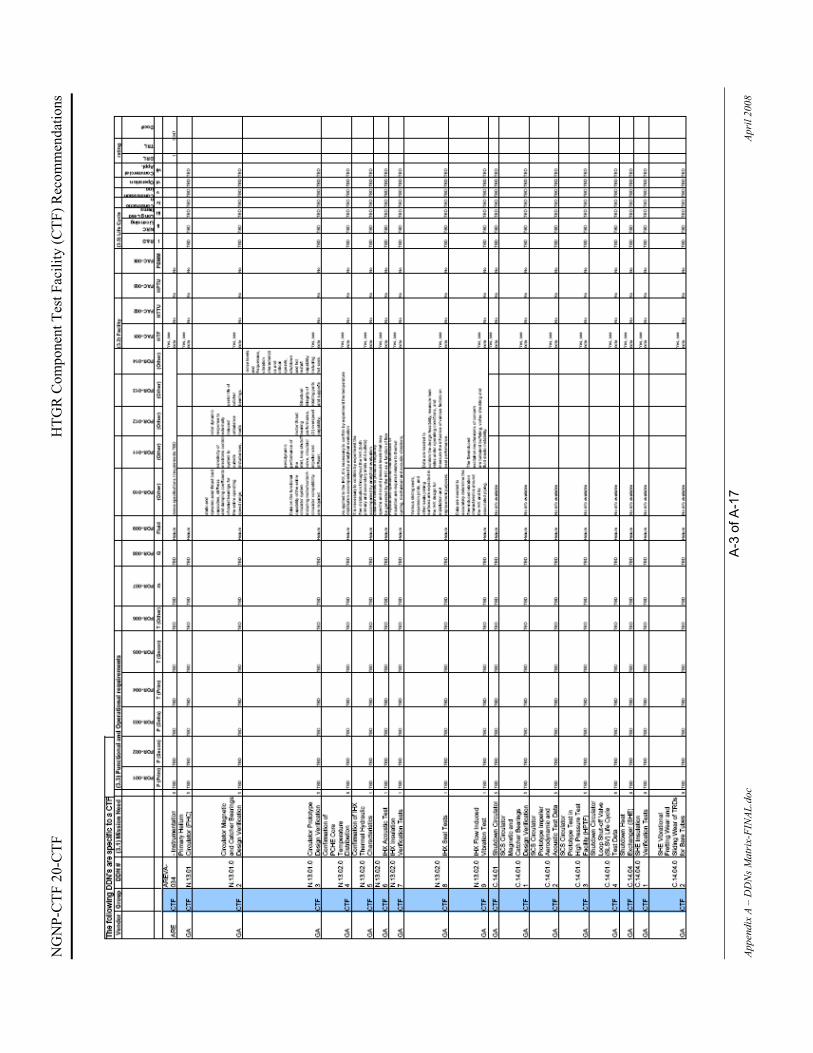
NG
NP-
CTF
20-
CTF
H
TGR
Com
pone
nt T
est F
acili
ty (C
TF) R
ecom
men
datio
ns
A-3
of A
-17
Appe
ndix
A –
DD
Ns M
atri
x-FI
NAL
.doc
Ap
ril 2
008

NG
NP-
CTF
20-
CTF
H
TGR
Com
pone
nt T
est F
acili
ty (C
TF) R
ecom
men
datio
ns
A-4
of A
-17
Appe
ndix
A –
DD
Ns M
atri
x-FI
NAL
.doc
Ap
ril 2
008

NG
NP-
CTF
20-
CTF
H
TGR
Com
pone
nt T
est F
acili
ty (C
TF) R
ecom
men
datio
ns
A-5
of A
-17
Appe
ndix
A –
DD
Ns M
atri
x-FI
NAL
.doc
Ap
ril 2
008
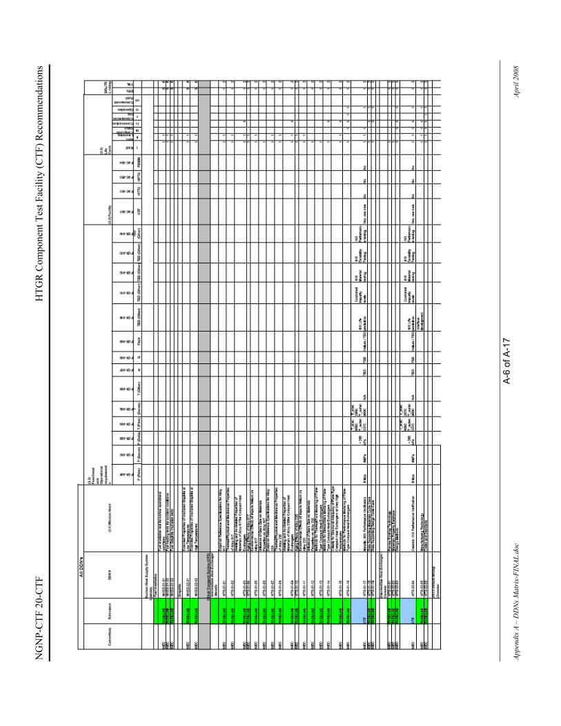
NG
NP-
CTF
20-
CTF
H
TGR
Com
pone
nt T
est F
acili
ty (C
TF) R
ecom
men
datio
ns
A-6
of A
-17
Appe
ndix
A –
DD
Ns M
atri
x-FI
NAL
.doc
Ap
ril 2
008

NG
NP-
CTF
20-
CTF
H
TGR
Com
pone
nt T
est F
acili
ty (C
TF) R
ecom
men
datio
ns
A-7
of A
-17
Appe
ndix
A –
DD
Ns M
atri
x-FI
NAL
.doc
Ap
ril 2
008

NG
NP-
CTF
20-
CTF
H
TGR
Com
pone
nt T
est F
acili
ty (C
TF) R
ecom
men
datio
ns
A-8
of A
-17
Appe
ndix
A –
DD
Ns M
atri
x-FI
NAL
.doc
Ap
ril 2
008

NG
NP-
CTF
20-
CTF
H
TGR
Com
pone
nt T
est F
acili
ty (C
TF) R
ecom
men
datio
ns
A-9
of A
-17
Appe
ndix
A –
DD
Ns M
atri
x-FI
NAL
.doc
Ap
ril 2
008

NG
NP-
CTF
20-
CTF
H
TGR
Com
pone
nt T
est F
acili
ty (C
TF) R
ecom
men
datio
ns
A-1
0 of
A-1
7 Ap
pend
ix A
– D
DN
s Mat
rix-
FIN
AL.d
oc
Apri
l 200
8
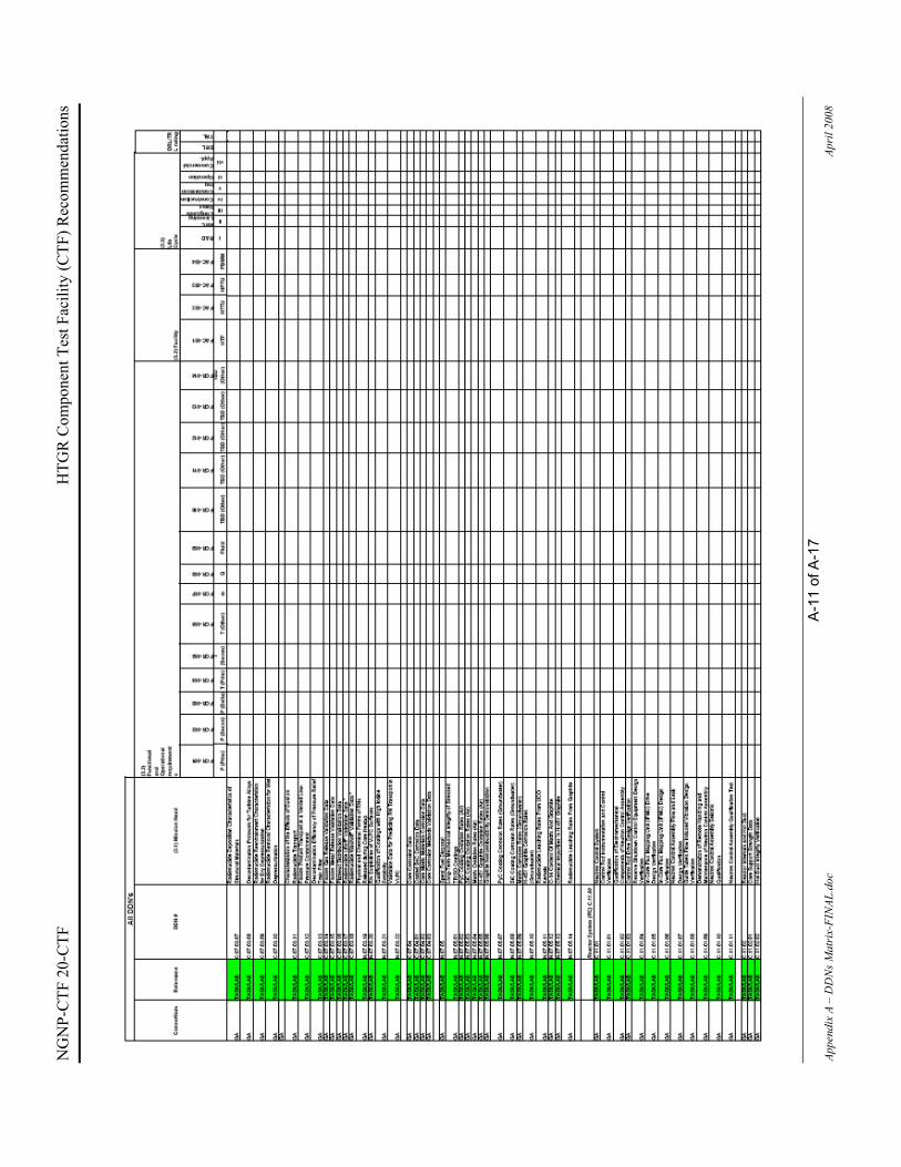
NG
NP-
CTF
20-
CTF
H
TGR
Com
pone
nt T
est F
acili
ty (C
TF) R
ecom
men
datio
ns
A-1
1 of
A-1
7 Ap
pend
ix A
– D
DN
s Mat
rix-
FIN
AL.d
oc
Apri
l 200
8

NG
NP-
CTF
20-
CTF
H
TGR
Com
pone
nt T
est F
acili
ty (C
TF) R
ecom
men
datio
ns
A-1
2 of
A-1
7 Ap
pend
ix A
– D
DN
s Mat
rix-
FIN
AL.d
oc
Apri
l 200
8

NG
NP-
CTF
20-
CTF
H
TGR
Com
pone
nt T
est F
acili
ty (C
TF) R
ecom
men
datio
ns
A-1
3 of
A-1
7 Ap
pend
ix A
– D
DN
s Mat
rix-
FIN
AL.d
oc
Apri
l 200
8

NG
NP-
CTF
20-
CTF
H
TGR
Com
pone
nt T
est F
acili
ty (C
TF) R
ecom
men
datio
ns
A-1
4 of
A-1
7 Ap
pend
ix A
– D
DN
s Mat
rix-
FIN
AL.d
oc
Apri
l 200
8

NG
NP-
CTF
20-
CTF
H
TGR
Com
pone
nt T
est F
acili
ty (C
TF) R
ecom
men
datio
ns
A-1
5 of
A-1
7 Ap
pend
ix A
– D
DN
s Mat
rix-
FIN
AL.d
oc
Apri
l 200
8

NG
NP-
CTF
20-
CTF
H
TGR
Com
pone
nt T
est F
acili
ty (C
TF) R
ecom
men
datio
ns
A-1
6 of
A-1
7 Ap
pend
ix A
– D
DN
s Mat
rix-
FIN
AL.d
oc
Apri
l 200
8

NG
NP-
CTF
20-
CTF
H
TGR
Com
pone
nt T
est F
acili
ty (C
TF) R
ecom
men
datio
ns
A-1
7 of
A-1
7 Ap
pend
ix A
– D
DN
s Mat
rix-
FIN
AL.d
oc
Apri
l 200
8

NGNP-CTF 20-CTF HTGR Component Test Facility (CTF) Recommendations
B-1 of B-27 Appendix B - SA PBMR Facilities-FINAL.doc April 2008
APPENDIX B - SOUTH AFRICAN PBMR TEST FACILITIES
1.1 HELIUM TEST FACILITY (HTF)
1.1.1 Background
The Helium Test Facility (HTF) is a facility for the development, verification and non-nuclear testing of critical prototype components of the PBMR and Support System. It provides the capability to test components and sub-assemblies in a high-temperature and high-pressure helium environment that are similar to the operating conditions expected for the PBMR demonstration plant.
The HTF will be used for testing of the following PBMR Demonstration Plant systems, sub-systems and components, also defined as Units Under Test (UUT):
� Fuel Handling and Storage System (FHSS) � Reactivity Control System (RCS) � Reserve Shutdown System (RSS) � Helium Inventory Control System (HICS) � Gas Cycle Valves (GCV) � Instrumentation � MPS Recuperator
The HTF is situated on the premises of NECSA, at Pelindaba, near Pretoria. The facility consists of a totally enclosed 40m high (8 levels) test tower with a 10m x 13m footprint and a 20 ton overhead crane with a passenger lift (ground - level 6). The facility is designed to accommodate 5 independent process streams, which are able to operate at up to 9MPa, 50ºC - 580ºC (1100ºC local) and up to 2kg/s. A simplified PFD of the HTF, indicating the maximum temperatures in the different lines is indicated in Figure 1.

NG
NP-
CTF
20-
CTF
H
TGR
Com
pone
nt T
est F
acili
ty (C
TF) R
ecom
men
datio
ns
B-2
of B
-27
Appe
ndix
B -
SA P
BMR
Faci
litie
s-FI
NAL
.doc
Ap
ril 2
008
Figu
re 1
: Sim
plifi
ed H
TF P
FD

NGNP-CTF 20-CTF HTGR Component Test Facility (CTF) Recommendations
B-3 of B-27 Appendix B - SA PBMR Facilities-FINAL.doc April 2008
Figure 2: Photo of HTF
1.1.2 HTF Envelope
The HTF is subjected to a list of Acceptance Test Procedures (ATPs), in order to demonstrate the required thermal-hydraulic performances as specified in the design and requirement documentation. These ATPs are summed up in Table 1, and will be conducted in three phases. These three phases are distinguished by the maximum temperature limit on the complete facility.
Table 1: Test phases
Phase Maximum Temperature limit Commissioned date Phase 1 Tmax = 300°C (Mainloop) End 2006 Phase 2 Tmax < 580°C (Mainloop) Mid 2008 Phase 3 Tmax < 900°C (Local in test set-up) Mid 2009
A complete summary of the operating envelope in the different sections of the HTF is presented in Table 2. From these specifications it can be concluded that the HTF does have the potential for addressing certain of the CTF needs. This potential would however need to be assessed according to availability of the different conditions.

NG
NP-
CTF
20-
CTF
H
TGR
Com
pone
nt T
est F
acili
ty (C
TF) R
ecom
men
datio
ns
B-4
of B
-27
Appe
ndix
B -
SA P
BMR
Faci
litie
s-FI
NAL
.doc
Ap
ril 2
008
Tabl
e 2:
HTF
The
rmal
-flui
d co
nditi
ons
and
avai
labi
lity
No.
Des
crip
tion
Pres
sure
[MPa
][k
g/s]
[°C
][k
g/s]
[°C
][k
g/s]
[°C
][k
g/s]
[°C
][k
g/s]
[°C
][k
g/s]
[°C
]kg
/s[°
C]
Dat
e
1FH
SS
@ 1
MPa
Lin
e D
, T =
280
°C (v
ia F
HS
sys
tem
)X
1-
-0.
051
280
--
--
--
--
0.05
128
0[T
BD
]
2FH
SS
@ 1
MPa
Lin
e G
, T =
200
- 25
0°C
(via
equ
alis
atio
n lin
e)X
1-
--
--
--
--
-0.
0325
00.
0325
0[T
BD
]
3FH
SS
@ 1
MPa
Lin
e G
, T =
280
°C (v
ia F
HS
sys
tem
)X
1-
--
--
--
--
-0.
1328
00.
1328
0[T
BD
]
4R
SS
@ 2
.2 M
Pa &
T_m
ax <
250
°CX
2.2
0.05
250
0.05
600.
0560
0.15
100
0.05
50-
-0.
0525
0[T
BD
]
5R
SS
@ 6
.5 M
Pa &
T_m
ax <
300
°CX
6.5
0.05
300
0.05
100
0.05
100
0.03
100
0.05
50-
-0.
0530
0[T
BD
]
6R
SS
@ 6
.5 M
Pa &
T_m
ax <
600
°CX
6.5
0.05
500
0.05
100
0.05
100
0.03
100
0.05
50-
-0.
0550
0[T
BD
]
7R
SS
@ 9
.0 M
Pa &
T_m
ax <
300
°C (S
AS
tran
spor
t)X
90.
0530
00.
0528
00.
0528
00.
415
00.
0550
--
0.05
300
[TB
D]
8R
SS
@ 9
.0 M
pa &
T_m
ax <
600
°C (S
AS
tran
spor
t)X
90.
0558
00.
0528
00.
0528
00.
415
00.
0550
--
0.05
580
[TB
D]
9R
SS
@ 9
.0 M
pa &
T_m
ax <
900
°C (S
AS
tran
spor
t)X
90.
0575
00.
0528
00.
0528
00.
415
00.
0550
--
0.05
750
[TB
D]
10R
SS
@ 9
.0 M
pa &
T_m
ax <
600
°C (M
anifo
ld D
for l
ower
RS
S v
esse
l co
nditi
onin
g at
350
°C)
X9
0.05
580
0.1
350
0-
0-
0.05
50-
-0.
0558
0[T
BD
]
11R
SS
@ 9
.0 M
pa &
T_m
ax <
900
°C (M
anifo
ld D
for l
ower
RS
S v
esse
l co
nditi
onin
g at
350
°C)
X9
0.05
750
0.1
350
0-
0-
0.05
50-
-0.
0575
0[T
BD
]
12R
CS
@ 9
.0 M
Pa &
T_m
ax <
300
°CX
90.
230
00.
0628
00.
0528
00.
0512
00.
0550
--
0.2
300
[TB
D]
13R
CS
@ 9
.0 M
Pa &
T_m
ax <
600
°CX
90.
258
00.
0628
00.
0528
00.
0520
00.
0550
--
0.2
580
[TB
D]
14R
CS
@ 9
.0 M
Pa &
T_m
ax <
600
°CX
90.
0590
00.
0528
00.
0528
00.
415
00.
0550
--
0.05
900
[TB
D]
15R
CS
@ 9
.0 M
Pa &
T_m
ax <
300
°C (N
o m
anifo
ld C
flow
)X
90
-0.
0628
00.
0518
00.
0512
00.
0550
--
0.06
280
[TB
D]
16R
CS
@ 9
.0 M
Pa &
T_m
ax 6
00°C
(No
man
ifold
C fl
ow)
X9
0-
0.06
350
0.05
180
0.05
120
0.05
50-
-0.
0635
0[T
BD
]
17R
CS
@ 9
.0 M
Pa &
T_m
ax <
600
°C (N
o m
anifo
ld A
& E
flow
)X
90.
2258
00.
0635
00
-0
-0.
0550
--
0.22
580
[TB
D]
18R
CS
@ 9
.0 M
Pa &
T_m
ax <
900
°C (N
o m
anifo
ld A
& E
flow
)X
90.
2290
00.
0635
00
-0
-0.
0550
--
0.22
900
[TB
D]
19C
ombi
ned
RC
S &
RS
S @
9.0
MPa
& T
_max
< 3
00°C
X9
0.25
300
0.11
0.1
0.9
280
0.35
120
0.9
50-
-0.
2530
0[T
BD
]
20C
ombi
ned
RC
S &
RS
S @
9.0
MPa
& T
_max
< 6
00°C
X9
0.25
580
0.11
280
0.9
280
0.35
120
0.1
50-
-0.
2558
0[T
BD
]
21FH
SS
@ 9
.0 M
Pa,T
=280
°C (v
ia e
qual
isat
ion
line)
X9
--
--
--
--
--
0.6
280
-0
-
22FH
SS
@ 9
.0 M
Pa,T
=280
°C (v
ia F
HS
sys
tem
)X
9-
--
--
--
--
-0.
5828
0-
0-
Max
imum
Con
ditio
ns9
0.25
900
0.11
350
0.9
280
0.4
200
0.9
500.
628
0
Not
es1
Tem
pera
ture
mea
sure
d at
man
ifold
C2
Tem
pera
ture
at n
ozzl
e of
RS
S te
st s
et-u
p ve
ssel
(N6)
3M
anifo
ld D
use
d fo
r con
ditio
ning
of R
SS
ves
sel b
otto
m4
Tem
pera
ture
at n
ozzl
e of
RS
S te
st s
et-u
p ve
ssel
(N8)
5Te
mpe
ratu
re a
t noz
zle
of R
SC
test
set
-up
vess
el (N
8)6
Tem
pera
ture
at n
ozzl
e of
RS
S (N
6) a
nd R
CS
(N8)
test
set
-up
vess
els
7Te
mpe
ratu
re w
ithin
bor
ing
(to
be a
chiv
ed w
ith h
eate
r H1,
H2
and
H5
or
inte
rnal
RS
S h
eatin
g)8
Bor
ing
tem
pera
ture
abo
ve 5
80 to
be
achi
eved
with
H6
Phase I
Phase II
Phase III
Lab
Ava
ilibi
ltyE
F
Man
ifold
Line
GC
DA

NGNP-CTF 20-CTF HTGR Component Test Facility (CTF) Recommendations
B-5 of B-27 Appendix B - SA PBMR Facilities-FINAL.doc April 2008
1.1.3 Proposed Modification to HTF
The HTF currently has an empty laboratory with development potential. This laboratory is intended to be a versatile facility for testing of PBMR components in a high pressure high-temperature helium environment. The provided conditions in the laboratory are determined from the main loop capabilities. The conditions that could be available from the main loop consist of three lines (A, C and F) as indicated in Figure 3. The same laboratory could also be utilized for a complete separate CTF loop, which uses the existing auxiliaries (HICBS & HPS) as well as added benefits from existing know-how. A typical arrangement of these two loops is indicated in Figure 3.
Figure 3: Proposed HTF lab configuration
The auxiliaries (HICBS & HPS) would be available for a new CTF loop. The proposed loop will consist of a blower with ±1 kg/s capability at 9 MPa. A similar blower is currently used by the HTF and can be ordered from HOWDEN. The loop will be able to test a number of the DDNs under the requirement achievable with this blower capacity.
FRO
M H
ICBS
TO H
ICBS
Primary Loop:1. Fluid: Helium 2. Pressure 9 Mpa3. ±1 kg/s (TBS)4.
Secondary Loop:1. Fluid: Helium 2. Pressure 9 Mpa3. ±1 kg/s (TBS)
T: 950°C
T: 3
37°C
T: 2
90°C
T: 9
00°C
FRO
M H
PS
TO H
PS
FRO
M H
PS
TO H
PS
Tertiary loopTertiary loop
Tertiary loop

NGNP-CTF 20-CTF HTGR Component Test Facility (CTF) Recommendations
B-6 of B-27 Appendix B - SA PBMR Facilities-FINAL.doc April 2008
1.1.4 HTF Summary Although Figure 1 shows the HTF as being available, this must not be misunderstood as being available for the CTF testing. This merely indicates availability for PBMR DPP testing. The HTF was purpose-built to address specific needs for the PBMR Demonstration Power Plant (DPP), as can be seen from the design and complex PFD of the HTF. The plant, as it is functioning currently, could not be used as the CTF and modifications/extensions of the existing facility would be needed.
The HTF infrastructure, human capital and knowledge make this a very attractive facility to use for component testing. The support systems like the HICBS & HPS are already built and functional. The time schedule, however, indicates that it will not be feasible as an option for component testing due to the primary commitments of the facility to the DPP. A timeframe of FY12 is indicated by the HTF team as a possibility, making it too late for the CTF time schedule requirements.

NGNP-CTF 20-CTF HTGR Component Test Facility (CTF) Recommendations
B-7 of B-27 Appendix B - SA PBMR Facilities-FINAL.doc April 2008
1.2 PEBBLE BED MICRO MODEL (PBMM)
1.2.1 Background
The purpose of the Pebble Bed Micro Model (PBMM) was to demonstrate the concept and controllability of the PBMR three-shaft recuperated closed Brayton Cycle. The PBMM was also utilized to demonstrate the Flownex computer code’s ability to accurately predict the dynamic behavior of the system.
The first phase of the PBMM project was to prove the feasibility of a three-shaft recuperative Brayton cycle. The next phase in the PBMM project was to gather experimental data for the verification and validation (V&V) of Flownex. During this phase, all instrumentation was calibrated to traceable standards to ensure reliable experimental data.
The Pebble Bed Micro Model (PBMM) is a fully functional model of the earlier three-shaft Power Conversion Unit (PCU) of the Pebble Bed Modular Reactor (PBMR), a predecessor of that currently under development in South Africa. Flownex was used extensively in the design of the PBMM and the prediction of its performance.
The PBMM is based on the Brayton power cycle (as used in aircraft engines) but with the following distinguishing features:
� It uses nitrogen as the working fluid. � The gas moves around in a closed circuit, which implies that no nitrogen is consumed in
the power generation process – it merely acts as an energy carrier. � The PBMM uses single stage centrifugal compressors and turbines. It makes use of three
separate shafts, one for the high-pressure (HP) compressor/turbine pair, one for the low pressure (LP) compressor/turbine pair and one for the power turbine (PT) and generator. This allows the HP and LP compressor/turbine pairs to run at high speeds thereby reducing the size and therefore also the cost of the machines.
� It makes use of a recuperator to recover heat that would otherwise have been rejected to atmosphere. The recovered heat is transferred elsewhere in the system thereby reducing the heat required from the heat source and ultimately increasing the thermal efficiency of the plant.
� The generator is emulated by a load compressor connected to a power dissipation loop consisting of a flow control valve and a heat exchanger. Variations in load are effected by increasing or decreasing the pressure level in the load rejection loop.

NGNP-CTF 20-CTF HTGR Component Test Facility (CTF) Recommendations
B-8 of B-27 Appendix B - SA PBMR Facilities-FINAL.doc April 2008
Figure 4 : Solid model of PBMM
Figure 5 : Photo of PBMM

NGNP-CTF 20-CTF HTGR Component Test Facility (CTF) Recommendations
B-9 of B-27 Appendix B - SA PBMR Facilities-FINAL.doc April 2008
1.2.2 PBMM Envelope
Table 3 : PBMM Envelope
Variable Unit Min Max
System Pressure MPa(abs) 0 0.9
System Mass Flow Rate kg/s 0 2 System Heater Power kW 0 350 Heater Temperature C 0 700 Fluid Nitrogen
1.2.3 Proposed Modifications to PBMM
Extensive modifications are needed to change the current facility for use as a component test facility or laboratory. The major changes will include a blower, pipe work, new control systems and instrumentation. The use of Helium in the facility has to be further investigated as sealing of the vessel will be of concern.
1.2.4 PBMM Summary
The PBMM successfully completed all the tests specified, and the facility is still fully operational and immediately available. Localized temperatures of 700 degree C at a pressure of 0.9 MPa at a maximum flow rate of 2 kg/s can be achieved. The system was design with Nitrogen as the working fluid. The PBMM is not an ASME accredited facility and extensive changes/modification are needed to address the DDN requirements. The PBMM is not well suited for addressing the CTF mission needs.

NGNP-CTF 20-CTF HTGR Component Test Facility (CTF) Recommendations
B-10 of B-27 Appendix B - SA PBMR Facilities-FINAL.doc April 2008
1.3 HEAT TRANSFER TEST FACILITY (HTTF)
The Heat Transfer Test Facility (HTTF) consists of two clearly distinguishable test units, namely the High Temperature Test Unit (HTTU) and the High Pressure Test Unit (HPTU). The purpose of the facility is twofold namely:
� To validate the correlations that are currently used to model the relevant heat transfer and fluid flow phenomena required for the integrated simulation of the pebble bed core, via a comprehensive set of separate effects tests.
� To generate results that may be used to validate the different simulation methodologies applied in the integrated models that represent the entire pebble bed core, via a comprehensive set of integrated effects tests.
1.3.1 High Temperature Test Unit (HTTU)
The HTTU is an integrated effects test facility that represents a section of the pebble bed reactor. The HTTU pebble annulus is the same width and geometrically similar to the actual PBMR and it will be used to measure the heat transfer characteristics of the pebble bed as a whole. Some of the tests that will be conducted with the HTTU will be used to validate correlations currently employed by PBMR for the determination of the pebble-to-pebble effective conductivity, pebble-to-reflector conductivity and temperature profiles through the core for different gas flow rates. These tests include steady-state and transient experiments with nitrogen and helium under different conditions. The high temperature pebble bed core or test section forms the heart of the HTTU plant. The test section contains about 28,000 graphite spheres of similar size to those of the PBMR fuel spheres.
1.3.1.1 Background
The HTTU will contribute to both of the objectives listed above since it will be used for the following:
� Steady-state separate effects tests under near-vacuum conditions to validate the correlations used for the pebble-to-pebble effective conductivity, as well as the pebble-to-reflector effective conductivity.
� Steady-state integrated effects tests under natural convection conditions at elevated temperatures to determine the temperature profiles through the core.
� Steady-state integrated effects tests under forced convection isothermal conditions to determine the velocity profiles through the core for different flow rates.
� Steady-state integrated effects tests under forced convection conditions at elevated temperatures to determine the temperature profiles and pressure drops through the core for different flow rates.
� Transient integrated effects tests under near-vacuum conditions at elevated temperatures in order to determine the temperature profiles and the thermal energy storage characteristics of the core.

NGNP-CTF 20-CTF HTGR Component Test Facility (CTF) Recommendations
B-11 of B-27 Appendix B - SA PBMR Facilities-FINAL.doc April 2008
� Transient integrated effects tests under natural convection conditions at elevated temperatures in order to determine the temperature profiles and the thermal energy storage characteristics of the core.
� Transient integrated effects tests under forced convection conditions at elevated temperatures in order to determine the temperature profiles and the thermal energy storage characteristics of the core for different flow rates.
Figure 6 : High Temperature Test Unit (HTTU) process flow diagram (PFD)

NGNP-CTF 20-CTF HTGR Component Test Facility (CTF) Recommendations
B-12 of B-27 Appendix B - SA PBMR Facilities-FINAL.doc April 2008
Figure 7: View of the HTTU near the end of construction

NGNP-CTF 20-CTF HTGR Component Test Facility (CTF) Recommendations
B-13 of B-27 Appendix B - SA PBMR Facilities-FINAL.doc April 2008
Figure 8 : View of the HTTU after construction (one of four blower vessels in the foreground)
The HTTU plant consists of one main vessel section with an adjoining gas pipe network that can be configured to obtain different test results. These configurations are the Vacuum/Natural Convection-, Forced Convection- and Velocity profile measurement configuration. Figure 9 below illustrates two of the three configurations.

NGNP-CTF 20-CTF HTGR Component Test Facility (CTF) Recommendations
B-14 of B-27 Appendix B - SA PBMR Facilities-FINAL.doc April 2008
Figure 9: The HTTU in Vacuum/Natural Convection configuration (Left) and Forced Flow configuration (Right).

NGNP-CTF 20-CTF HTGR Component Test Facility (CTF) Recommendations
B-15 of B-27 Appendix B - SA PBMR Facilities-FINAL.doc April 2008
Figure 10: Gas flow path during the Forced Flow configuration
1.3.1.2 HTTU Steady-State Tests
Steady-State Tests Natural Convection High Temperature
Experiment 1: Nitrogen at 1200°C
This experiment will be a steady-state integrated effects test with Nitrogen under natural convection conditions at elevated temperatures.
The test pressure will be 100kPa with the inner wall temperature maintained at 1200°C. The inlet water temperature of the water jacket will be maintained at 25°C and the outlet 35°C. The top and bottom boundaries will be insulated.
Experiment 2: Helium at 1200°C
This experiment will be a steady-state integrated effects test with Helium under natural convection conditions at elevated temperatures.

NGNP-CTF 20-CTF HTGR Component Test Facility (CTF) Recommendations
B-16 of B-27 Appendix B - SA PBMR Facilities-FINAL.doc April 2008
The test pressure will be 100kPa with the inner wall temperature maintained at 1200°C. The inlet water temperature of the water jacket will be maintained at 25°C and the outlet 35°C. The top and bottom boundaries will be insulated.
Steady-State Tests Forced Convection Isothermal
Experiment 3: Nitrogen 0.5 kg/s isothermal
This experiment will be a steady-state integrated effects test with Nitrogen forced convection isothermal conditions to determine the velocity profile through the core.
The gas pressure at the inlet of the core will be maintained at 100kPa and the inlet temperature at 40°C. The flow rate will be 0.5 kg/s.
Experiment 4: Nitrogen 1 kg/s isothermal
This experiment will be a steady-state integrated effects test with Nitrogen forced convection isothermal conditions to determine the velocity profile through the core.
The gas pressure at the inlet of the core will be maintained at 100kPa and the inlet temperature at 40°C. The flow rate will be 1 kg/s.
Experiment 5: Nitrogen 2 kg/s isothermal
This experiment will be a steady-state integrated effects test with Nitrogen forced convection isothermal conditions to determine the velocity profile through the core.
The gas pressure at the inlet of the core will be maintained at 100kPa and the inlet temperature at 40°C. The flow rate will be 2 kg/s.
Experiment 6: Nitrogen 3 kg/s isothermal
This experiment will be a steady-state integrated effects test with Nitrogen forced convection isothermal conditions to determine the velocity profile through the core.
The gas pressure at the inlet of the core will be maintained at 100kPa and the inlet temperature at 40°C. The flow rate will be 3 kg/s.
Experiment 7: Nitrogen 4 kg/s isothermal
This experiment will be a steady-state integrated effects test with Nitrogen forced convection isothermal conditions to determine the velocity profile through the core.
The gas pressure at the inlet of the core will be maintained at 100kPa and the inlet temperature at 40°C. The flow rate will be 4 kg/s.

NGNP-CTF 20-CTF HTGR Component Test Facility (CTF) Recommendations
B-17 of B-27 Appendix B - SA PBMR Facilities-FINAL.doc April 2008
Steady-State Tests Forced Convection High Temperature
Experiment 8: Nitrogen 0.5 kg/s at 1200°C
This experiment will be a steady-state effects test with Nitrogen under forced convection conditions at elevated temperatures to determine the temperature profile and pressure drop through the core.
The gas pressure at the inlet of the core will be maintained at 100kPa and the inlet temperature at 40°C. The flow rate will be 0.5 kg/s. The inner wall temperature will be maintained at 1200°C. The inlet water temperature of the water jacket will be maintained at 25°C and the outlet temperature at 35°C.
Experiment 9: Nitrogen 1kg/s at 1200°C
This experiment will be a steady-state effects test with Nitrogen under forced convection conditions at elevated temperatures to determine the temperature profile and pressure drop through the core.
The gas pressure at the inlet of the core will be maintained at 100kPa and the inlet temperature at 40°C. The flow rate will be1 kg/s. The inner wall temperature will be maintained at 1200°C. The inlet water temperature of the water jacket will be maintained at 25°C and the outlet temperature at 35°C.
Experiment 10: Nitrogen 2 kg/s at 1200°C
This experiment will be a steady-state effects test with Nitrogen under forced convection conditions at elevated temperatures to determine the temperature profile and pressure drop through the core.
The gas pressure at the inlet of the core will be maintained at 100kPa and the inlet temperature at 40°C. The flow rate will be 2 kg/s. The inner wall temperature will be maintained at 1200°C. The inlet water temperature of the water jacket will be maintained at 25°C and the outlet temperature at 35°C.
Experiment 11: Nitrogen 3 kg/s at 1200°C
This experiment will be a steady-state effects test with Nitrogen under forced convection conditions at elevated temperatures to determine the temperature profile and pressure drop through the core.
The gas pressure at the inlet of the core will be maintained at 100kPa and the inlet temperature at 40°C. The flow rate will be 3 kg/s. The inner wall temperature will be maintained at 1200°C. The inlet water temperature of the water jacket will be maintained at 25°C and the outlet temperature at 35°C.

NGNP-CTF 20-CTF HTGR Component Test Facility (CTF) Recommendations
B-18 of B-27 Appendix B - SA PBMR Facilities-FINAL.doc April 2008
Experiment 12: Nitrogen 4 kg/s at 1200°C
This experiment will be a steady-state effects test with Nitrogen under forced convection conditions at elevated temperatures to determine the temperature profile and pressure drop through the core.
The gas pressure at the inlet of the core will be maintained at 100kPa and the inlet temperature at 40°C. The flow rate will be 4 kg/s. The inner wall temperature will be maintained at 1200°C. The inlet water temperature of the water jacket will be maintained at 25°C and the outlet temperature at 35°C.
1.3.1.3 HTTU Envelope
The following table indicates the test plans for the HTTU for the next two years. The current planning indicates that the tests specified for the HTTU will be completed by the end of 2009.
Table 4: HTTU Experimental Test Plan
Experiment Pressure [kPa (abs)]
MassFlow Rate
[kg/s]
Temperature [°C]
Fluid[ ]
Completion date
Steady-state test - near vacuum - high temperature
10 0 1600 Nitrogen Nov ‘09
Steady-state test – natural convection - high temperature
100 0 1200 Nitrogen Nov ‘09
Steady-state Test – Forced convection – isothermal
100 0.5 40 Nitrogen Nov ‘09
Steady-state Test – Forced Convection – high temperature
100 0.5 1200 Nitrogen Nov ‘09
Transient Test – near vacuum – high temperature
10 0 1200 to 1600
Nitrogen Nov ‘09
Transient test – natural convection – high temperature
100 0 1000 to 1600
Helium Nov ‘09
Transient test – forced convection – high temperature
100 0.5 1200 Nitrogen Nov ‘09
Table 5 : HTTU Envelope
Variable Unit Min Max
System Pressure kPa (abs) 10 100
System Mass Flow Rate - Nitrogen kg/s 0 0.5 System Heater Power kW 0 500 Heater Temperature ºC 0 1600 Heat Exchanger Power kW 0 157 Fluid Helium & Nitrogen

NGNP-CTF 20-CTF HTGR Component Test Facility (CTF) Recommendations
B-19 of B-27 Appendix B - SA PBMR Facilities-FINAL.doc April 2008
1.3.1.4 Proposed Modifications to HTTU
The HTTU has both helium and nitrogen inventory systems, but no control and purification of these systems. High temperatures can be reached but extensive modifications are needed to address the requirement for component testing. The HTTU can for example be used as a specialized laboratory for material testing but the current test schedule makes this only possible in 2010.
1.3.1.5 HTTU Summary
The HTTU is fully commissioned and operational. The proposed test schedule indicates that the plant will be available in 2010 for other work. The HTTU heater consists of a graphite core structure and has been designed to deliver 1600ºC helium and nitrogen that can be used as a fluid within the main heater chamber. The system can be operated under 10 kPa (abs) vacuum conditioning. A forced flow of 0.5 kg/s can be reached at a core temperature of 1200ºC. The HTTU is not an ASME accredited facility, but was designed to ASME specifications.
1.3.2 High Pressure Test Unit (HPTU)
The HPTU operates at a system pressure of 50 bar and a temperature of 75°C, using nitrogen as the working fluid. As mentioned earlier, the HPTU consists of a number of test sections, each evaluating different parameters and reactor phenomena.
The aim of the HPTU is to validate the correlations that are used for different heat transfer and fluid flow phenomena through comprehensive Separate Effects Tests (SET), and to validate the different simulation methodologies used in the integrated models through comprehensive Integrated Effects Tests (IET). It should be noted that the HPTU is not an exact scale model of the actual reactor core or any other reactor structures. It is merely an assortment of representative sections of a pebble bed core, suitable for conducting SET and IET.
Construction on the HPTU started in September 2005 and operation commenced a year later, in September 2006.
Due to the shape, distribution and material properties of the pebbles, various thermal fluid phenomena exist inside the reactor. The HPTU attempts to validate correlations that are used in the modeling of the following phenomena:

NGNP-CTF 20-CTF HTGR Component Test Facility (CTF) Recommendations
B-20 of B-27 Appendix B - SA PBMR Facilities-FINAL.doc April 2008
Figure 11: The thermal-fluid phenomena that the HPTU attempts to validate: A) Average porosity distribution, B) Pebble-to-pebble effective conductivity, C) Pebble-
to-reflector effective conductivity, D) Velocity distribution, E) Fluid effective conductivity (braiding effect), F) Pebble-to-fluid convective heat transfer and G)
Reflector-to-fluid convective heat transfer

NGNP-CTF 20-CTF HTGR Component Test Facility (CTF) Recommendations
B-21 of B-27 Appendix B - SA PBMR Facilities-FINAL.doc April 2008
1.3.2.1 Background
The HPTU will contribute to both of the objectives listed above since it will be used for the following:
� Steady-state separate effects tests to validate the correlations used for the pebble-to-fluid heat transfer coefficient at different porosities.
� Steady-state separate effects tests to validate the correlations used for the reflector surface-to-fluid heat transfer coefficient.
� Steady-state separate effects tests to determine the total pressure drop through a homogeneous packed bed at different porosities.
� Steady-state separate effects tests to determine the effective fluid heat conduction due to turbulent mixing at different porosities.
� Steady-state integrated effects tests to determine the total pressure drop through an annular packed bed.
� Steady-state integrated effects tests to determine the effective fluid heat conduction due to turbulent mixing in an annular packed bed.
� Steady-state integrated effects tests to determine the velocity profile at the outlet of the annular packed bed.
� Steady-state integrated effects tests to determine the total pressure drop through a cylindrical packed bed.
� Steady-state integrated effects tests to determine the effective fluid heat conduction due to turbulent mixing in a cylindrical packed bed.
� Steady-state integrated effects tests to determine the velocity profile at the outlet of the cylindrical packed bed.

NGNP-CTF 20-CTF HTGR Component Test Facility (CTF) Recommendations
B-22 of B-27 Appendix B - SA PBMR Facilities-FINAL.doc April 2008
Figure 12 : HPTU PFD
Figure 13 : Photo of HPTU

NGNP-CTF 20-CTF HTGR Component Test Facility (CTF) Recommendations
B-23 of B-27 Appendix B - SA PBMR Facilities-FINAL.doc April 2008
1.3.2.2 HPTU Tests
Pressure Drop Test Section (PDTS)
The PDTS will be used to evaluate steady-state separate effects tests to validate the correlations used for the pressure drop at different porosities. There will be 3 different PDTSs to provide for the 3 different porosities required. The geometry of the PDTS has a square cross section with the basic dimensions of 300mm x 300mm x 720mm. This test section will consist of spheres with a diameter of 28.575mm. The pressure drop will be measured by means of an array of differential pressure transducers on the outside of the pressure vessel. The pressure drop will then be determined by means of measurements positioned at the inlet and outlet of the packed bed.
Figure 14: A) A closer look at the pebble bed, which will be used for pressure drop measurements. B) A detail look inside the test section, showing the pebbles, C)
Indication of the PDTS layout.
Convection Coefficient Test Section (CCTS)
The CCTS will be used to investigate steady-state separate effects to validate the correlations used for the pebble-to-fluid heat transfer coefficient at different porosities. There will be three different CCTS inserts to provide for three different porosities. The CCTSs have a square cross sectional area of 300mm x 300mm and are 720mm long. The length of the porous bed region varies and is dictated by the different porosities.

NGNP-CTF 20-CTF HTGR Component Test Facility (CTF) Recommendations
B-24 of B-27 Appendix B - SA PBMR Facilities-FINAL.doc April 2008
Figure 15: A) An illustration of the poisoning of the Ball Heater inside pebble bed. B) An exploded view of the Ball Heater and thermocouple, C) Indication of the CCTS
layout.
Near Wall Test Section (NWTS)
The NWTS will be used to evaluate steady-state separate effects tests to validate the correlations used for the wall-to-fluid heat transfer coefficient at an average (not homogeneous) porosity. There will be one NWTS to provide for the one porosity required. The NWTS has a rectangular cross section of 300mm x 112 mm and it is 720 mm long. There will only be two rows of spheres to simulate the two walls of the packed bed. The geometry presents a bilaterally symmetric control volume with average porosity of 0.45 in the near wall region. This test section consists of 60 mm diameter spheres. The measurement requirements of the NWTS consist only of the surface temperature of the heated strip. All sides of the rectangular heated strip are isolated, except for the heated surface.
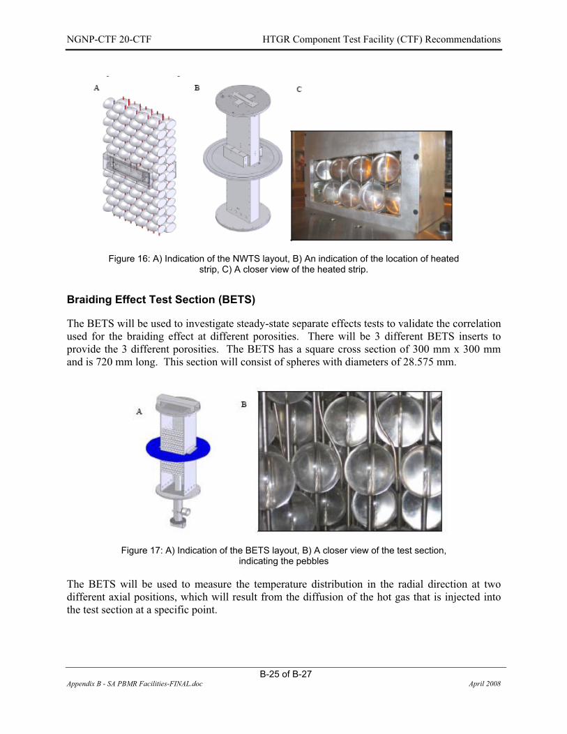
NGNP-CTF 20-CTF HTGR Component Test Facility (CTF) Recommendations
B-25 of B-27 Appendix B - SA PBMR Facilities-FINAL.doc April 2008
Figure 16: A) Indication of the NWTS layout, B) An indication of the location of heated strip, C) A closer view of the heated strip.
Braiding Effect Test Section (BETS)
The BETS will be used to investigate steady-state separate effects tests to validate the correlation used for the braiding effect at different porosities. There will be 3 different BETS inserts to provide the 3 different porosities. The BETS has a square cross section of 300 mm x 300 mm and is 720 mm long. This section will consist of spheres with diameters of 28.575 mm.
Figure 17: A) Indication of the BETS layout, B) A closer view of the test section, indicating the pebbles
The BETS will be used to measure the temperature distribution in the radial direction at two different axial positions, which will result from the diffusion of the hot gas that is injected into the test section at a specific point.

NGNP-CTF 20-CTF HTGR Component Test Facility (CTF) Recommendations
B-26 of B-27 Appendix B - SA PBMR Facilities-FINAL.doc April 2008
Small Annular and Small Cylindrical Packed Beds (SAPB and SCPB)
The SAPB and SCPB test sections will be used to evaluate certain integrated effects on a complete scaled model of the PBMR core. The geometry of the SAPB represents a radially scaled model of the PBMR core with a length of 30 sphere diameter, while the SCPB has the same outer diameter as the SAPB but with no central column. Both the SAPB and SCPB will make use of 6 mm diameter spheres. The total number of spheres needed is determined by the SCPB and amounts to approximately 110,000. The measurements that will be taken consist of the temperature and velocity profile at the exit of the test section as well as the pressure drop over the test section.
Figure 18: A) Indication of the BETS layout, B) A closer view of the test section, indicating the pebbles
1.3.2.3 HPTU Envelope
Table 6 : HPTU Envelope
Variable Unit Min MaxCompletion date
System Pressure kPa 100 5000 Jan ‘08 System Mass Flow Rate kg/s 0.01117 2.888 Jan ‘08Braiding Mass Flow Rate kg/s 0.001532 0.12480 Jan ‘08System Heater Power kW 0.03491 9.668 Jan ‘08Braiding Heater Power kW 0.127 5.481 Jan ‘08Heat Exchanger Power kW 0.04507 0.04507 Jan ‘08
1.3.2.4 Proposed Modifications to HPTU
Extensive modifications (localized heating and cooling) are required to reach high temperatures (T>900 ºC) and that at only 50 bar.

NGNP-CTF 20-CTF HTGR Component Test Facility (CTF) Recommendations
B-27 of B-27 Appendix B - SA PBMR Facilities-FINAL.doc April 2008
1.3.2.5 HPTU Summary
The HPTU is fully operational and at the end of its testing phase. The test for the PBMR will be completed at the end of Jan 2008. The plant was designed to function at a pressure of 5 MPa (50 Bar) at a temperature of 35 ºC. A maximum mass flow rate of 2.8 kg/s can be reached with the orbital blowers. The HPTU is not an ASME accredited facility, but was designed according to it. It will not be feasible to use this facility for component testing.

NGNP-CTF 20-CTF HTGR Component Test Facility (CTF) Recommendations
C-1 of C-19 Appendix C - Literature Study Component Test Facilities-FINAL.doc April 2008
APPENDIX C - LITERATURE STUDY ON OTHER FACILITIES
1. INTRODUCTION A hydrogen economy is proposed to solve the ill effects of using hydrocarbon fuels in transportation, and other so-called, stationary end-use applications where the carbon is released to the atmosphere. Some references propose a closed synthetic hydrocarbon-CO2 cycle instead of the hydrogen-water cycle to eliminate difficulties related to the production, transport and use of hydrogen [Bossel 2003].
In the current hydrocarbon economy, the transportation of people and goods (so-called mobileapplications) is fueled primarily by petroleum, refined into gasoline and diesel, and natural gas. However, the burning of these hydrocarbon fuels causes the emission of greenhouse gases and other pollutants. Furthermore, the supply of hydrocarbon resources in the world is limited, and the demand for hydrocarbon fuels is increasing, particularly in China, India and other developing countries.
2. NGNP PROJECT Since 2005 South Africa has been actively involved with the pre-conceptual design of the DOE funded Next Generation Nuclear Power Plant (NGNP) Project. This project is considered to form part of the GENERATION IV initiative aimed at identifying a reactor system for producing electricity and hydrogen, which excelled at meeting the GENERATION IV goals related to safety, sustainability, proliferation resistance, physical security, and economics.
3. COMPONENT TEST FACILITY All methods of hydrogen production, apart from the photolytic methods of synthesis, can in principle be coupled to a nuclear reactor to provide electricity and process heat. Conventional light-water reactors (LWR) can be employed for example, to deliver electricity for the low temperature electrolysis process; electricity and hydrogen production are separated effectively and could even be deployed at different locations. Different reactor types with higher coolant outlet temperatures would allow the direct utilization of the hot medium which transfers heat to a chemical process. In such cases, the H2 production site must be in close proximity of the nuclear site. Mutual utilization of the basic reactor design for electricity and process heat generation was a fundamental requirement in the former German HTGR industrial development programs. This applied specifically to the past projects on direct gas turbine cycles (HHT), steam cycles (THTR-300, HTR-500) and the various nuclear process heat projects, PNP (Prototype nuclear process heat) and NFE (Nuclear long distance energy).
A fundamental difference between the electricity and the process heat market is the power size distribution of the energy supply system. Large plants have been favoured for dedicated electricity generation, whereas the non-electric energy market favours small and medium-sized Combined Heat and Power (CHP) plants due to the limited size of heat distribution networks and

NGNP-CTF 20-CTF HTGR Component Test Facility (CTF) Recommendations
C-2 of C-19 Appendix C - Literature Study Component Test Facilities-FINAL.doc April 2008
due to very high availability requirements requiring redundant, modular power supply systems. Different CHP applications clearly indicate that the power size of a 200-300 MWt modular design would well fit the needs of industrial heat consumers whereas the 600 MWt GT-MHR already represents an upper limit. A modular arrangement (2-6 units) will be necessary for redundancy, reliability and reserve capacity, which again requires a smaller power size per module. However, smaller power size allows for simplicity and robustness by higher safety margins even at higher operational temperatures if necessary at all.
Nuclear reactor and hydrogen plant will be physically separated from each other by employing an intermediate heat exchanger (IHX) between the primary helium circuit of the reactor and the steam reformer/steam generator system. All applications with IHX require helium outlet temperatures from the reactor to be 900°C or higher to realize a compact IHX component with a larger temperature difference across the IHX. The design of a plant with 850°C coolant outlet temperature and IHX is also feasible, but at the expense of a much larger heat transfer surface.
As part of the ongoing NGNP work MTECH is tasked to perform a first order cost estimation of a component loop test facility. Based on the specifications provided by INEL of the various participants the loop facility at hand is conceptually designed for purposes of the costing. Due to past experience of especially the Germans in the field of high temperature reactor technology it is deemed sensible to summarize the component and loop test facilities operated in Germany. Facilities of note constructed and operated elsewhere are also listed in what follows.
4. LIST OF COMPONENT AND LOOP TEST FACILITIES
4.1 DEVELOPMENT AND TESTING OF AN IHX IN GERMANY
In Germany the concept was investigated of a combination of the HTR-Modul with an IHX. In Figure 1 the layout is represented of the German reference design for a process heat HTR-Modul in a side by side arrangement of nuclear reactor and IHX vessel for each modular unit. The thermal power rating of the nuclear reactor and the IHX are 170 MW. The power limit is determined by the requirement of inherent decay heat removal capability in a depressurized loss of forced cooling (DLOFC) event. If larger thermal powers were needed, an annular core would be required. The limit in that case is caused by the dimensions and type of reactor pressure vessel. Details of the IHX with helical tube bundle are shown in Figure 2.
The employment of an IHX was also suggested within the PNP project with regard to the steam gasification of hard coal, for which the main characteristic data are also given in the table for comparison.

NGNP-CTF 20-CTF HTGR Component Test Facility (CTF) Recommendations
C-3 of C-19 Appendix C - Literature Study Component Test Facilities-FINAL.doc April 2008
Figure 1: Arrangement of HTR-Module (a) with Helix-IHX (b) or U-tube-IHX (c) [IA 1983]

NGNP-CTF 20-CTF HTGR Component Test Facility (CTF) Recommendations
C-4 of C-19 Appendix C - Literature Study Component Test Facilities-FINAL.doc April 2008
Figure 2: Intermediate heat exchanger for nuclear applications [Kugeler 2005] - helical tube bundle (left), details of hot gas collector tube and support structures (right).
The Helical coil IHX (see Figure 2) consists of a bundle of helical tubes arranged around a central return gas duct for the hot secondary helium. The support system for the tubes consists of support cylinders with star-shaped, welded-on support plates designed to carry the weight of the bundle. A segmental design of the support structure limits the relative axial expansion caused by the operation temperature. In the upper cold area, the mechanical loads are carried by the vessel cover. This ensures access to the secondary system for in-service inspection and repairs without the necessity to open the primary circuit.

NGNP-CTF 20-CTF HTGR Component Test Facility (CTF) Recommendations
C-5 of C-19 Appendix C - Literature Study Component Test Facilities-FINAL.doc April 2008
Figure 3: Flow sheet of 10 MW KVK facility for testing nuclear process heat components
A facility for large component testing (KVK) was constructed and successfully operated by INTERATOM as part of the PNP project [Harth 1990]. In a heating system consisting of a heater with steam, a natural gas burner, and an electrical heater with a total thermal power of 10 MW, helium was heated up to 950°C at 4.0 MPa (Figure 3 and Figure 4). This plant also allowed for testing of the hot gas ducts with large diameter, of a steam generator, valves for hot helium and other components like hot headers or auxiliary plants, such as gas purification.

NGNP-CTF 20-CTF HTGR Component Test Facility (CTF) Recommendations
C-6 of C-19 Appendix C - Literature Study Component Test Facilities-FINAL.doc April 2008
Figure 4: 10 MW KVK facility for testing nuclear process heat components.
Two IHX components were constructed and tested in the KVK loop, one with a helical tube bundle and another one with U-tubes. In Figure 5 the schematics are shown of both components. In Figure 6 and Figure 7 the IHX components are depicted still under construction.

NGNP-CTF 20-CTF HTGR Component Test Facility (CTF) Recommendations
C-7 of C-19 Appendix C - Literature Study Component Test Facilities-FINAL.doc April 2008
Figure 5: Two IHX components tested in KVK - Helical tube bundle by Steinmüller company (left), U-tube bundle by Balcke-Dürr company (right)

NGNP-CTF 20-CTF HTGR Component Test Facility (CTF) Recommendations
C-8 of C-19 Appendix C - Literature Study Component Test Facilities-FINAL.doc April 2008
Figure 6: IHX component with helical tube bundle tested in KVK (Steinmüller)
Figure 7: INX Component with U-tube bundle tested in KVK (Balcke-D�rr)

NGNP-CTF 20-CTF HTGR Component Test Facility (CTF) Recommendations
C-9 of C-19 Appendix C - Literature Study Component Test Facilities-FINAL.doc April 2008
4.2 TESTING OF THE JAPANESE IHX IN THE HTTR
The IHX used in the HTTR is a vertical, helically coiled counter flow type heat exchanger as shown in Figure 8. The primary helium enters the IHX through the inner pipe of the primary concentric hot gas duct attached to the bottom of the IHX. It flows upwards outside the tubes transferring the nuclear heat of 10 MW to the secondary helium cooling system and flows back through the annular space between the inner and outer shells. The secondary helium flows downwards inside the heat transfer tubes and flows upwards in the central hot gas pipe through the hot header.
Figure 8: Schematic and photograph of the He-He intermediate heat exchanger in the HTTR.
A double-walled shell with a thermal insulation attached on the inside surface of the inner shell provides reliable separation of heat resisting and pressure retaining functions. Cold helium flowing through the annulus brings uniform temperature distribution throughout the outer shell, which has a pressure-retaining function.

NGNP-CTF 20-CTF HTGR Component Test Facility (CTF) Recommendations
C-10 of C-19 Appendix C - Literature Study Component Test Facilities-FINAL.doc April 2008
Insulation inside and outside the central hot gas pipe keeps the heat transfer low to obtain a high efficiency.
4.3 IHX DESIGN CONCEPT FOR THE US H2-MHR In the United States, the reference design for a next generation HTGR is the 600 MWt Modular Helium Reactor (MHR). For the purpose of hydrogen generation, the concept of an H2-MHR has been developed which is to be coupled to a H2 production technology based on either S-I thermo-chemical cycle or high temperature electrolysis. The intermediate heat exchanger for this facility is based on a design of so-called “Printed Circuit Heat Exchangers”, PCHE, developed by the Heatric company (see Figure 9) [NERI 2003, HEATRIC].
Figure 9: Printed Circuit Heat Exchanger, PCHE (source: HEATRIC) A heat exchanger module is composed of metal plate layers containing alternately coolant channels for the primary and
for the secondary fluid flowing (e.g.) counter to each other (top right).
The flow channels with a semi-circular profile (top left) are chemically etched into the plates using a technique similar to that for printing electrical circuits. This manufacturing technique makes complex streams possible. The metal plates are stacked (top right) and then diffusion-bonded, where the metal surfaces are pressed together promoting a grain growth between the plates, thus becoming a solid all-metal core (bottom left). PCHE designs have been developed

NGNP-CTF 20-CTF HTGR Component Test Facility (CTF) Recommendations
C-11 of C-19 Appendix C - Literature Study Component Test Facilities-FINAL.doc April 2008
which are highly compact, highly robust (bottom right) and which have high thermal efficiencies, allowing pressures of 50 MPa and temperatures of 900°C.
4.4 GERMAN CONCEPTS OF HELIUM-HEATED STEAM REFORMING
In comparison to a conventional steam reformer, the employment of a nuclear steam reformer requires certain changes, since operational conditions of a nuclear reactor are not that flexible as a fossil-fueled furnace. Also safety requirements are much more stringent than for a fossil-fuelled system. It is therefore desired to achieve highest effectiveness in utilizing the nuclear process heat in the whole production process system. A large H2 production rate is achieved, if the process feed gas rate and the conversion rate are high. The feed gas rate depends on the amount of heat input into process gas and the temperature of process gas. The conversion rate depends on temperature and pressure of the process gas.
A principle flow sheet of an HTGR with steam reformer, where all heat for the reforming process, the steam production, gas purification, and gas compression can be gained from the helium circuit, is shown in Figure 10. The stages of gas purification include the shift conversion, CO2 scrubber, H2 separation, and a methanation reaction to remove traces of carbon oxides from the process gas. The typical temperature profiles along a splitting tube are shown in Figure 11.
Figure 10: Principal flow sheet of HTGR with SR [Kugeler 2005] Legend: 1 - HTGR, 2 - steam reformer, 3 - steam generator, 4 - He blower, 5 - preheater gas, 6 - preheater gas, 7 - shift
conversion, 8 - CH4 preheater, 9 - CO2 washer, 10 - H2/CH4 separation, 11 - me

NGNP-CTF 20-CTF HTGR Component Test Facility (CTF) Recommendations
C-12 of C-19 Appendix C - Literature Study Component Test Facilities-FINAL.doc April 2008
Figure 11: T-diagram for use of heat in HTGR with SR [Kugeler 2005].
Nuclear steam reforming of methane was the subject of extensive R&D activities in Germany in the 1970-1980s. Within the NFE (Nuclear Long-Distance Energy Transportation) project, large test facilities were constructed and successfully operated at FZJ to study the steam reforming process and also the reverse process of methanation under nuclear conditions.
Steam reforming was investigated in the EVA single splitting tube test facility, later in EVA-II [Verfondern 2007] representing bundles of reformer tubes. The latter used an electrical heater with a power of 10 MW to heat up helium gas to a temperature of 950°C at 4.0 MPa (see Figure 12, top). In the connected steam reformer, the heat between 950°C and 650°C was used to run the steam reforming process. In the connected steam generator (helical tubes, power 4 MW), the helium heat was used up to 350°C.
Via a helium circulator, the cold helium was routed back to the electrical heater. The circuit was operated under nuclear conditions at a lower power level, but with a full-scale SR component. Also the process gas handling system was the same as in a nuclear plant.
In a methanation plant, ADAM, the product gas was reconverted to methane and steam, thus completing a closed cycle without any CO2 emissions (see Figure 12, bottom). With regard to the power input of 10 MWe, the heat release rate achieved in the ADAM plant was 5.3 MWt. The so-called ADAM & EVA [Verfondern 2007] system represents a long-distance chemical heat transportation system based on hydrogen as the energy carrier.

NGNP-CTF 20-CTF HTGR Component Test Facility (CTF) Recommendations
C-13 of C-19 Appendix C - Literature Study Component Test Facilities-FINAL.doc April 2008
Figure 12: Flow sheet of steam reforming test facility EVA-II (top) and of combined test facilities EVA-II and ADAM-II (bottom) (source: FZJ).

NGNP-CTF 20-CTF HTGR Component Test Facility (CTF) Recommendations
C-14 of C-19 Appendix C - Literature Study Component Test Facilities-FINAL.doc April 2008
Two reformer bundles have been tested in the EVA-II facility: a bundle with guiding tubes (annulus design) for each reformer tube (5 MW, 18 tubes) and a bundle with baffle structures (disks and doughnuts) on the helium side (6 MW, 30 tubes). The tubes and catalytic system were 1:1 scale compared to components planned for nuclear applications. Also the loads imposed on the supporting structures were characteristic to the nuclear case. Both have operated without any difficulties for more than 6000 h.
Figure 13 shows the component with guiding tubes tested in EVA-II. Both designs of a steam reformer bundle are shown in Figure 14. The specific data of reformer tubes investigated were very similar to the respective design for nuclear applications.
Figure 13: Steam reformer bundles tested in EVA-II (source: FZJ). (a) Schematic of annulus (left), baffle design (right). (b) Photo of baffle design steam reformer bundle.

NGNP-CTF 20-CTF HTGR Component Test Facility (CTF) Recommendations
C-15 of C-19 Appendix C - Literature Study Component Test Facilities-FINAL.doc April 2008
Figure 14: Steam reformer bundle of baffle design (top) and annulus design (bottom)

NGNP-CTF 20-CTF HTGR Component Test Facility (CTF) Recommendations
C-16 of C-19 Appendix C - Literature Study Component Test Facilities-FINAL.doc April 2008
4.5 EVO AND HHV
Oberhausen II [IAEA 1984], operated by the German utility EVO (Energie Versorgung Oberhausen AG), is a 50 MW(e) direct-cycle Helium turbine plant (Figure 15). The power source is a gas burner rather than a nuclear reactor core, but the power conversion system resembles those of the GFR (Gas-cooled Fast Reactor) and other high-temperature reactor concepts. Oberhausen II was operated for more than 25 000 hours between 1974 and 1988. Design specifications, drawings and experimental data have been obtained through the European HTR-E project, offering a unique opportunity to validate codes on a large-scale Brayton cycle. Available measurements of temperature, pressure and mass flow rate throughout the circuit have allowed a very comprehensive thermohydraulic description of the plant, in steady-state conditions for design data and operating data as well as during transients.
The HHV has an electrically-driven turbo machinery consisting of a 2-stage turbine and an 8-stage compressor on a single-shaft arrangement with a synchronous rotational speed of 3,000 rpm. Figure 16 shows a picture of the HHV turbine. The compressor requires 90 MW power, the turbine power produces about 46 MW, and the electric motor supplies 45 MW. The mass flow rate is about 200 kg/s.
During the initial operation, oil ingress and excessive helium leakage occurred. After the problems were corrected, the HHV [IAEA 1984] test plant was successfully operated for about 1,100 hours, and the measured results showed that the helium gas turbine had a higher efficiency than the design value. They found that creep and fatigue crack growth at high temperature with impurities such as carbon in the helium coolant comprises the main mechanism limiting the lifetime of the turbine blades and disks. Also, it was estimated that the lifetimes of uncooled turbine components are around 50,000-60,000 hours and that the maximum temperature with uncooled metallic blades and disks is 850°C.

NGNP-CTF 20-CTF HTGR Component Test Facility (CTF) Recommendations
C-17 of C-19 Appendix C - Literature Study Component Test Facilities-FINAL.doc April 2008
Figure 15: High-pressure Turbine Rotor from EVO in Germany.

NGNP-CTF 20-CTF HTGR Component Test Facility (CTF) Recommendations
C-18 of C-19 Appendix C - Literature Study Component Test Facilities-FINAL.doc April 2008
Figure 16: Rotor from HHV in Germany

NGNP-CTF 20-CTF HTGR Component Test Facility (CTF) Recommendations
C-19 of C-19 Appendix C - Literature Study Component Test Facilities-FINAL.doc April 2008
References�1. Bossel U., Eliasson B., Energy and the Hydrogen Economy, 8 January 2003.
2. IA, Nukleare Prozesswärmeanlagen mit Hochtemperaturreaktor-Modul zur Kohleveredlung, Technical Report ITB 78.10122.8, Kraftwerk Union AG, INTERATOM/GHT (1983).
3. Kugeler K., et.al., Technical and Safety Aspects of Processes of Hydrogen Production Using Nuclear Energy, Int. Congress on Advances in Nuclear Power Plants ICAPP 05, May 15-19, 2005, Seoul, Korea, Paper 5729.
4. B Harth R., et.al., Experience Gained from the EVA II and KVK Operation, Nucl. Eng. Des. 121 (1990) 173-182.
5. NERI, Nuclear Energy Research Initiative, Annual Report, General Atomics, San Diego, USA (2003).
6. IAEA Specialists Meeting on Heat Exchanging Components of Gas-Cooled Reactors, R. Harth, H. F. Niessen, V. Vau & R. Merken, Düsseldorf, 16 – 19 April 1984.
7. Nuclear Energy for Hydrogen Production, Karl Verfondern (Ed), FZJ Report, 2007.
8. PBMR, (http://www.pbmr.co.za).
9. JJ van der Merwe, R Bollen, JP van Ravenswaay, VALIDATION AND VERIFICATION OF FLOWNEX NUCLEAR, Proceedings HTR2006: 3rd International Topical Meeting on High Temperature Reactor Technology October 1-4, 2006, Johannesburg, South Africa.
10. HEATRIC, (http://www.heatric.com/compact_heat_exchangers.html).

NGNP-CTF 20-CTF HTGR Component Test Facility (CTF) Recommendations
D-1 of D-51 Appendix D - Concept1 detail-FINAL.doc April 2008
APPENDIX D CONCEPT 1 DETAILS
1.1 TEST CONFIGURATIONS
In order to provide a recommendation with regards to facility enveloping sizes, a number of different test configurations were imposed on Concept 1. These test configurations are summarized in Table 1, and were each evaluated in terms of energy balances. A complete summary of these energy balances, together with general considerations per test configuration can be found in at the end of this appendix. The “TEST#” column in Table 1 corresponds with the “DOCUMENT NUMBER” on the energy balance sheet.
Table 1: Summary of Test Configurations in Concept 1 as Dictated by the DDNs
Test # Main Test Configuration Sub Test TDL # IHX-W_1 IHX Performance verification tests: WEC
Core A � Test core size of 1.34 MW � Prescribed mass flow � Defined inlet and outlet temperatures
Steady state TDL 1
IHX-W_2 IHX Performance verification tests: WEC Core B
� Test core size of 2 MW � Prescribed mass flow � Defined inlet and outlet temperatures
Steady state TDL 1
IHX-W_3 IHX Performance verification tests: WEC Core A
� No heat transfer to secondary loop � Primary side to accommodate high
temperature in recuperator � Resulting in large duty recuperator
Loss of secondary side pressure & flow
TDL 1
IHX-W_4 IHX Performance verification tests: WEC Core B
� No heat transfer to secondary loop � Primary side to accommodate high
temperature in recuperator � Resulting in large duty recuperator
Loss of secondary side pressure & flow
TDL 1
IHX-G_1 IHX Performance verification tests: GA (Maximum test core size)
� Determining possible test core size (small) from known conditions
� Mass flow ( same as for WEC) � Test core temperatures from PCDR � Resulting test core: 2.14 MW � Test core size to evaluated for
feasibility � Large duty on recuperator
Steady state TDL 1
IHX-G_2 IHX Performance verification tests: GA (Maximum qualification core size)
� Determining possible qualification core size (large) from known conditions
Steady state CQL

NGNP-CTF 20-CTF HTGR Component Test Facility (CTF) Recommendations
D-2 of D-51 Appendix D - Concept1 detail-FINAL.doc April 2008
Test # Main Test Configuration Sub Test TDL # � Mass flow (High value per TDL) � Qualification core temperatures from
PCDR � Resulting qualification core: ~10 MW � Qualification core size to evaluated
for feasibility IHX-A_1 IHX Performance verification tests: AREVA
(Maximum test core size) � Determining possible test core size
(small) from known conditions. � Secondary side to be tested with He-
N2. Calculation based on He only. � Mass flow ( same as for WEC) � Test core temperatures from PCDR � Resulting test core: ~2.45 MW � Test core size to be evaluated for
feasibility
Steady state TDL 2
IHX-A_2 IHX Performance verification tests: AREVA (Maximum qualification core size)
� Use all three TDL mass flow & duty capabilities
� Three TDLs determine maximum representative core size which can be tested
� Resulting test core: ~11 MW � Maximum required Recuperator size: :
~7.8 MW
Steady state CQL
MIX-W_1 Mixing chamber performance verification: WEC
� Prescribed Mixing Chamber test temperatures
� Prescribed mass flow Minimum heater flow rate
Steady state TDL 1
DIV-W_1 High temperature ducts & insulation performance verification test: WEC (small scale)
� Prescribed test temperature: 950°C � Determine maximum heater outlet
temperature � TDL to accommodate high temperature
in recuperator
Steady state TDL 3
DIV-W_2 High temperature ducts & insulation performance verification test: WEC (large scale)
� Use all three TDL mass flow & duty capabilities
� Three TDLs determine maximum representative mass flow and duty available
Maximum return header temperature
Steady state CQL
SG-W_1 Steam generator performance verification test: WEC
Steady state CQL

NGNP-CTF 20-CTF HTGR Component Test Facility (CTF) Recommendations
D-3 of D-51 Appendix D - Concept1 detail-FINAL.doc April 2008
Test # Main Test Configuration Sub Test TDL # CIR-W Circulator performance: WEC
� Circulator requirements from WEC � Determine maximum flow rate in loop � Determine pipe size & flow velocity
Steady state Circulator loop
CIR-G Circulator performance: GA � Circulator requirements from GA � Determine maximum temperature in
loop � Determine maximum cooler
temperature � Determine minimum operating
envelope for mass flow and heat duty of cooler
� Determine loop materials & insulation requirements
Steady state Circulator loop
CIR-A Circulator performance: AREVA � Circulator requirements from WEC � Determine maximum flow rate in loop � Determine pipe size & flow velocity
Steady state Circulator loop
The enveloping values for each TDL will be presented in the following sections from these test configurations and the energy balances.

NGNP-CTF 20-CTF HTGR Component Test Facility (CTF) Recommendations
D-4 of D-51 Appendix D - Concept1 detail-FINAL.doc April 2008
1.2 TECHNOLOGY DEVELOPMENT LOOP 1
This loop consists of both a primary and a secondary loop, and its main sizing requirements are based on the IHX test core requirements as from the Westinghouse consortium. Both the primary and secondary loops are sized with only helium. In addition to IHX testing, this small loop also provides for testing of various components in dedicated fully instrumented test vessels in both the primary and secondary loop for temperatures up to 950°C. It is also envisaged that TDL1 will provide connection flanges for future testing of varying secondary loop contents such as liquid salt configurations for hydrogen production. This capability is provided in the form of extra connection points to the primary circuit test vessel. Additional capabilities of this loop also include testing of mixing chambers, by means of additional piping to the test station vessel in the primary circuit.
IHX Vessel
Test Station:
Recuperator
Recuperator
Cooling gas
IHX C&I
Dust Generator
Test Station Instrumentation
Requirements: Testing of- Hot circuit piping- Isolation valves- Mixing chambers- IHX LS
Test Station Vessel Primary side : Helium
Secondary side : Helium
To CQ
L
From CQLFilter station
H 1.1
C 1.1
RX 1.1
TS 1.1DG 1.1 IHX 1.1 FS 1.1
CL 1.1
TS 1.2
Heater
RX 1.2
C 1.2
CL 1.2
LP Tank
LP 2.2
AC 1.1
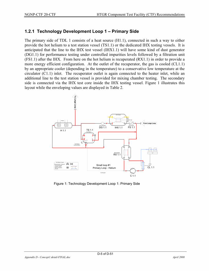
NGNP-CTF 20-CTF HTGR Component Test Facility (CTF) Recommendations
D-5 of D-51 Appendix D - Concept1 detail-FINAL.doc April 2008
1.2.1 Technology Development Loop 1 – Primary Side
The primary side of TDL 1 consists of a heat source (H1.1), connected in such a way to either provide the hot helium to a test station vessel (TS1.1) or the dedicated IHX testing vessels. It is anticipated that the line to the IHX test vessel (IHX1.1) will have some kind of dust generator (DG1.1) for performance testing under controlled impurities levels followed by a filtration unit (FS1.1) after the IHX. From here on the hot helium is recuperated (RX1.1) in order to provide a more energy efficient configuration. At the outlet of the recuperator, the gas is cooled (CL1.1) by an appropriate cooler (depending in the temperature) to a conservative low temperature at the circulator (C1.1) inlet. The recuperator outlet is again connected to the heater inlet, while an additional line to the test station vessel is provided for mixing chamber testing. The secondary side is connected via the IHX test core inside the IHX testing vessel. Figure 1 illustrates this layout while the enveloping values are displayed in Table 2.
IHX Vessel
Test Station:
Recuperator
Cooling gas
IHX C&I
Dust Generator
Test Station Instrumentation
Requirements: Testing of- Hot circuit piping- Isolation valves- Mixing chambers- IHX LS
Test Station Vessel
Primary Loop : HeliumSmall loop #1
To Large Loop
From Large LoopFilter station
H 1.1
C 1.1
RX 1.1
TS 1.1DG 1.1 IHX 1.1 FS 1.1
CL 1.1
Heater
Figure 1: Technology Development Loop 1: Primary Side

NGNP-CTF 20-CTF HTGR Component Test Facility (CTF) Recommendations
D-6 of D-51 Appendix D - Concept1 detail-FINAL.doc April 2008
Table 2: Enveloping Values of the Primary Side of Technology Development Loop 1
TDL 1 – Primary side
No. Components Power [MW]
Mass flow rate [kg/s] -
MAX T_in [°C]
T_out [°C] Pressure Fluid
C 1.1 Circulator (�P: 500 kPa @ 5 MPa) 0.2 [max] 2 80
[min] -
RX 1.1 Recuperator (Hot side) 1.75 950 [max]
260 [max]
RX 1.1 Recuperator (Cold side)
6.3 [max] 1.75 ~ 85
[max] 776
[max]
H 1.1 Heater 4.0 1.75 776 [max]
950 [max]
TS 1.1 Vessel - Test Station N/A 1.75 950 [min]
950 [max]
DG 1.1 Dust Generator N/A 1.15 760 950
IHX 1.1 Heat exchanger Vessel (primary) N/A 1.15 950
[max] 950
[max]
CL 1.1 Cooler 1.6 1.75 260 [max]
80 [nom]
FS 1.1 Filtration station N/A 1.15 950 [max] PD 1.1 Pipe & Ducting N/A 1.75 950 [max]
5 – 9 MPa Pure Helium
1.2.2 Technology Development Loop 1 – Secondary Side
The secondary side of TDL 1 is connected to the primary side by means of the IHX test core and is also sized for helium alone. This loop is also envisaged to have a test station vessel for possible expansion while the rest of the loop is very similar to the primary side. The only difference is a mixing valve at the circulator (C1.2) outlet for controlling the IHX inlet temperature. Figure 2 illustrates the layout while the enveloping values are presented thereafter in Table 3.

NGNP-CTF 20-CTF HTGR Component Test Facility (CTF) Recommendations
D-7 of D-51 Appendix D - Concept1 detail-FINAL.doc April 2008
IHX Vessel
Recuperator
IHX C&I
Secondary Loop : Helium
RX 1.2
C 1.2
CL 1.2
LP Tank
LP 2.2
Figure 2: Technology Development Loop 1: Secondary Side
Table 3: Enveloping Values of the Secondary Side of Technology Development Loop 1
TDL 1 – Secondary side
No. Components Power [MW]
Mass flow rate [kg/s] -
MAX T_in [°C]
T_out [°C] Pressure Fluid
C 1.2 Circulator (�P: 500 kPa @ 5 MPa) 0.2 [max] 2 80
[min] -
RX 1.2 Recuperator (Hot side) 1.15 900 [max]
464 [max]
RX 1.2 Recuperator (Cold side)
3.7 [max] 1.15 ~ 85
[max] 756
[max]
TS 1.2 Vessel - Test Station N/A 1.15 900 [min]
900 [max]
CL 1.2 Cooler 2.0 [max] 1.15 464 [max]
80 [nom]
PD 1.2 Pipe & Ducting N/A 1.15 900 [max]
5 – 9 MPa Pure Helium

NGNP-CTF 20-CTF HTGR Component Test Facility (CTF) Recommendations
D-8 of D-51 Appendix D - Concept1 detail-FINAL.doc April 2008
1.3 TECHNOLOGY DEVELOPMENT LOOP 2
Technology Development Loop 2 (TDL2) has a similar configuration to that of TDL1, but differs in the fact that it does not provide a number of test station vessels. This loop is mainly proposed for investigation purposes of different fluids (such as He/N2 mixtures) in the secondary loop, while also allowing for concurrent IHX testing by various vendors. The secondary loop is currently sized with helium, and further investigation is necessary to determine the suitability of one circulator for both helium and He-N2 mixtures. It is however anticipated that a different circulator would be required for different fluids being tested.
1.3.1 Technology Development Loop 2 – Primary Side
The primary side of TDL 2 is similar to that of TDL 1, except that it does not have an additional test station vessel. Figure 3 illustrates the layout while the enveloping values are presented in Table 4.
IHX Vessel
Recuperator
IHX C&I
Primary Loop : HeliumSmall loop #2
From Large Loop
To Large Loop
H 2.1
C 2.1
CL 2.1
IHX 2.1
RX 2.1
Figure 3: Technology Development Loop 2: Primary Side

NGNP-CTF 20-CTF HTGR Component Test Facility (CTF) Recommendations
D-9 of D-51 Appendix D - Concept1 detail-FINAL.doc April 2008
Table 4: Enveloping Values of the Primary Side of Technology Development Loop 2
TDL 2 – Primary side
No. Components Power [MW]
Mass flow rate [kg/s] -
MAX T_in [°C]
T_out [°C] Pressure Fluid
C 2.1 Circulator (�P: 500 kPa @ 5 MPa) 0.2 [max] 2 80
[min] -
RX 2.1 Recuperator (Hot side) 1.75 950 [max]
257 [max]
RX 2.1 Recuperator (Cold side)
6.3 [max] 1.75 ~ 85
[max] 776
[max]
H 2.1 Heater 4.0 1.75 776 [max]
950 [max]
IHX 2.1 Heat exchanger Vessel (primary) N/A 1.15 900
[max] 900
[max]
CL 2.1 Cooler 1.6 1.75 257 [max]
80 [nom]
PD 2.1 Pipe & Ducting N/A 1.75 900 [max]
5 – 9 MPa Pure Helium
1.3.2 Technology Development Loop # 2 – Secondary Side
It is anticipated that the secondary side of TDL2 will be used with either helium or other fluids under testing, such as He-N2 / CO2 mixtures. Current sizing has been done using helium and further investigation still needs to be performed regarding the suitability of a single circulator. It is however anticipated that different circulators will be utilized with different fluids when tested. Figure 4 illustrates the process while the enveloping values are presented in Table 5.

NGNP-CTF 20-CTF HTGR Component Test Facility (CTF) Recommendations
D-10 of D-51 Appendix D - Concept1 detail-FINAL.doc April 2008
IHX Vessel
Recuperator
Secondary Loop : He-N2 / Other fluids
C 2.2
CL 2.2RX 2.2
Figure 4: Technology Development Loop 2: Secondary Side
Table 5: Enveloping Values of the Secondary Side of Technology Development Loop 2
TDL 2 – Secondary side
No. Components Power [MW]
Mass flow rate [kg/s] -
MAX T_in [°C]
T_out [°C] Pressure Fluid
C 2.2 Circulator (�P: 500 kPa @ 5 MPa) 0.2 [max] 2 80
[min] -
RX 2.2 Recuperator (Hot side) 1.15 850 [max]
455 [max]
RX 2.2 Recuperator (Cold side)
2.3 [max] 1.15 ~ 85
[max] ~ 700 [max]
CL 2.2 Cooler 2.2 [max] 1.15 455 [max]
80 [nom]
PD 2.2 Pipe & Ducting N/A 1.15 850 [max]
5 – 9 MPa
Sizing done
on Helium. Other
fluids to be
tested

NGNP-CTF 20-CTF HTGR Component Test Facility (CTF) Recommendations
D-11 of D-51 Appendix D - Concept1 detail-FINAL.doc April 2008
1.4 TECHNOLOGY DEVELOPMENT LOOP 3
Technology Development Loop 3 (TDL3) again uses the basic building blocks as proposed in TDL 1, but with the sole purpose of providing a test station for non heat transfer components, such as valves, ducting, insulation etc. It also serves the purpose for providing the additional energy input when the three loops are used concurrently and connected together in a common header. Technology Development Loop 3 also addresses the need for a separate facility due to long term test requirements and the possibility of time constraint issues.
1.4.1 Technology Development Loop 3 – Primary Side
The primary loop of TDL 3 is again similar to TDL 1 expect for the fact that it does not have separate vessels for IHX and component testing. It is anticipated that this loop will be used for non-heat transfer testing while the possibility exists for future expansion of commercial testing on the secondary side.
Figure 5 Illustrates this loop with its enveloping values presented thereafter in Table 6.
Test Station
Recuperator
Cooling gas
C&I
Primary Loop : HeliumSmall loop #3
To Large LoopFrom Large Loop
H 3.1
RX 3.1
C 3.1
CL 3.1
TS 3.1
Figure 5: Technology Development Loop 3: Primary Side

NGNP-CTF 20-CTF HTGR Component Test Facility (CTF) Recommendations
D-12 of D-51 Appendix D - Concept1 detail-FINAL.doc April 2008
Table 6: Enveloping Values of the Primary Side of Technology Development Loop 3
TDL 3 – Primary side
No. Components Power [MW]
Mass flow rate [kg/s] -
MAX T_in [°C]
T_out [°C] Pressure Fluid
C 3.1 Circulator (�P: 500 kPa @ 5 MPa) 0.2 [max] 2 80
[min] -
RX 3.1 Recuperator (Hot side) 1.75 950 [max]
257 [max]
RX 3.1 Recuperator (Cold side)
6.3 [max] 1.75 ~ 85
[max] 776
[max]
H 3.1 Heater 4.0 1.75 776 [max]
950 [max]
TS 3.1 Vessel - Test Station N/A 1.75 950 [min]
950 [max]
CL 3.1 Cooler 1.6 1.75 257 [max]
80 [nom]
PD 3.1 Pipe & Ducting N/A 1.75 950 [max]
5 – 9 MPa Pure Helium

NGNP-CTF 20-CTF HTGR Component Test Facility (CTF) Recommendations
D-13 of D-51 Appendix D - Concept1 detail-FINAL.doc April 2008
1.5 COMPONENT QUALIFICATION LOOP (CQL)
A component qualification loop (CQL) is also proposed as part of Concept 1. This component qualification loop is a larger facility which is required for larger scale component qualification of up to 10 MW, as dictated by certain design data needs. It is anticipated that the primary circuit of the CQL could utilize the heating, cooling and mass flow producing capabilities of the three smaller facilities, while a dedicated secondary loop is added.
Typical tests on this facility include large scale IHX cores of up to 10 MW, duct & insulation testing and fully representative size steam generators.
1.5.1 Component Qualification Loop – Primary Side
The primary side of the CQL is shown in Figure 6, and consists of common inlet and outlet headers, steam generator testing connections (SG 4.1) as well a testing vessel for heat transfer and non heat transfer components (in IHX 4.1). A dedicated steam loop is also provided for complete representative testing of steam generator components. The primary side also incorporates a recuperator (RX 4.1) to reduce the capacity of each heater in the TDLs. A summary of the components and values for the primary side is provided in Table 7.
TDL #1
TDL #2
TDL #3
TDL #1
TDL #2
TDL #3
Primary side : Helium
From N
GN
P
Test vessel for large component
qualification
TO N
GN
P
Recuperator
Large scale IHX testing
Steam GeneratorVessel
Feed Pre-heater
Air Cooled Condensers
IHX 4.1
RX 4.1
SG 4.1CL 4.1
Figure 6: Large Loop: Primary Side

NGNP-CTF 20-CTF HTGR Component Test Facility (CTF) Recommendations
D-14 of D-51 Appendix D - Concept1 detail-FINAL.doc April 2008
Table 7: Enveloping Values of the Primary Side of CQL
CQL – Primary side
No. Components Power [MW]
Mass flow rate [kg/s] -
MAX T_in [°C]
T_out [°C] Pressure Fluid
RX 4.1 Recuperator (Hot side) 5.25 950 [max]
657 [max]
RX 4.1 Recuperator (Cold side)
7.8 [max] 5.25 590
[max] 858
[max]
IHX 4.1 Heat exchanger Vessel (primary) N/A 5.25 950
[max] 590
[max]
SG 4.1 Steam generator (testing capability) 11.2 [max] 5.25 900
[max] 272
[nom] PD 4.1 Pipe & Ducting N/A 5.25 950 [max]
5 – 9 MPa Helium
1.5.2 Component Qualification Loop – Secondary Side
The secondary side of the CQL is connected to the primary side by means of the IHX test core (in IHX 4.1) as well the recuperator (RX 4.1). The loop further consists of an additional recuperator (RX 4.2) as well as the normal cooler and circulator arrangement. Figure 7 illustrates the proposed layout with the enveloping values presented thereafter.
RecuperatorRecuperator
Air Cooled Condensers
IHX 4.1
RX 4.1RX 4.2
CL 4.2
Secondary side: Helium
C 4.2
Figure 7: High Level Process Flow Diagram of the Circulator Loop Secondary Side

NGNP-CTF 20-CTF HTGR Component Test Facility (CTF) Recommendations
D-15 of D-51 Appendix D - Concept1 detail-FINAL.doc April 2008
Table 8: Enveloping Values of the Secondary Side of CQL
CQL – Secondary side
No. Components Power [MW]
Mass flow rate [kg/s] -
MAX T_in [°C]
T_out [°C] Pressure Fluid
C 4.2 Circulator (�P: 500 kPa @ 5 MPa) 0.6 [max] 6 80
[min] -
RX 4.2 Recuperator (Hot side) 5.25 657 [max]
184 [max]
RX 4.2 Recuperator (Cold side)
13.1 [max] 5.25 ~ 85
[max] 565
[max]
CL 4.2 Cooler 2.8 [max] 5.25 184 [max]
80 [nom]
PD 4.2 Pipe & Ducting N/A 5.25 925 [max]
5 – 9 MPa Helium.
1.5.3 Full Scale Circulator Loop
A full scale circulator testing loop is also proposed to address full scale testing requirements of different circulator designs. This separate loop is mainly proposed as part of the philosophy of not having 2 or more components under test in a single test configuration. A typical arrangement is shown in Figure 8, with a summary of the main components in Table 9.
Circulator Test loop
From H
ICS
From H
PS
C 5.1
CL 5.1
Figure 8: Circulator Test Loop

NGNP-CTF 20-CTF HTGR Component Test Facility (CTF) Recommendations
D-16 of D-51 Appendix D - Concept1 detail-FINAL.doc April 2008
Table 9: Enveloping Values of the Circulator Test Loop
Circulator test loop – Secondary side
No. Components Power [MW]
Mass flow rate [kg/s] -
MAX T_in [°C]
T_out [°C] Pressure Fluid
C 5.1 Circulator: Unit under test
12.4 MWt [max] 159.6 [max] 590
[max] -
CL 5.1 Cooler 12.4 [max] 159.6 [max] 590 [max]
272 [min]
PD 5.1 Pipe & Ducting N/A 159.6 [max] 590 [max]
5 – 9 MPa Helium.

NGNP-CTF 20-CTF HTGR Component Test Facility (CTF) Recommendations
D-17 of D-51 Appendix D - Concept1 detail-FINAL.doc April 2008
1.6 COMPONENT DESCRIPTIONS
This section provides a general description and recommendations for future work on the different components and sub systems of Concept 1.
1.6.1 Circulators
Circulator – TDL Primary & Secondary side
The circulator unit is used as the primary fluid mover in the process loop. The circulator should therefore be able to overcome the differential pressure demand at the required flow rate set by the individual process components, subsystems and units under test. The main requirement in terms of circulator capacity is usually driven by the units under test. Various options are available in terms of circulator type and design. However, aspects such as Helium leakage to atmosphere and contaminant into the process loop, drive the choice of design and will be discussed in the specific sections below.
� Circulator Process Requirements
The maximum flow rate required for the specified tests in the three TDLs is estimated at 1.75 kg/s. Provision is made for increased flow up to 2.0 kg/s which might be required for surge control by means of a bypass loop across the circulator. The required flow rate is easily obtained by a single stage high speed centrifugal design. A maximum pressure rise of 500 kPa is expected which results in a Pressure Ratio (PR) of 1.056 at an inlet pressure of 9000 kPa. The theoretical temperature rise across the compressor is calculated at 9.8°C with an inlet temperature of 80°C and isentropic efficiency of 80%. The required pumping power is calculated as approximately 200 kW.
� Circulator Drive To simplify the design of the circulator system and to ensure that the facility’s design integrity is one level higher than the units under test, it is recommended that the compressor uses a variable speed 2 pole electric motor and step up gearbox that is not submerged in the working fluid. This also eliminates the use of Active Magnetic Bearings (AMB) and the associated control systems. However, the circulator system should be designed in such a way to allow for later modifications in the event of a requirement for specifically testing AMB.
� Dry Gas Seal System
The compressor impeller is situated within the pressure boundary, with only a shaft penetration though the pressure boundary. The proposed sealing mechanism at this interface would be a dry gas seal. The dry gas seal would cause some leak to atmosphere but is assumed to be acceptable. If calculation shows that the leak is unacceptable, it is still possible to make use of the submerged type drive system.

NGNP-CTF 20-CTF HTGR Component Test Facility (CTF) Recommendations
D-18 of D-51 Appendix D - Concept1 detail-FINAL.doc April 2008
� Circulator Drive Lubrication
Provision should be made to lubricate the gearbox and associated bearings in the drive system of the compressor. The details of the lubrication system will be addressed at a later stage in the design. It is of utmost importance to specify the allowable concentration of lubricant (if any) in the gas stream during the next phases of design.
� Circulator Vessel
The compressor is housed in its own pressure boundary assembly, with only a shaft penetration. An inlet and outlet nozzle flange is attached to the pressure boundary. The vessel design should allow for future modification of the drive system to a submerged drive system with AMB.
Circulator – CQL Secondary side
The CQL secondary side circulator would follow the same design approach as followed for the TDL circulators. However, the CQL secondary side circulator is required to circulate 5.25 kg/s through the process. Provision is made for increased flow up to 6.0 kg/s which might be required for surge control by means of a bypass loop across the circulator. The required flow rate is obtained by a single stage high speed centrifugal design. A maximum pressure rise of 500 kPa is expected which results in a Pressure Ratio (PR) of 1.056 at an inlet pressure of 9000 kPa. The theoretical temperature rise across the compressor is calculated at 9.8°C with an inlet temperature of 80°C and isentropic efficiency of 80%. The required pumping power is calculated as approximately 600 kW.
1.6.2 Heater Unit – TDL Primary Side
The heater assembly used in the three TDLs is similar in design and constitutes a number of electric resistance heaters that are installed in series. The heater configuration was determined by examining a number of different test configurations which had several requirements. Heating is done by means of electric resistance elements to ease controllability of the power level for different test configurations. The suggested heater should supply a nominal duty of approximately 4MW. The maximum flow rate through the heater is 1.75 kg/s and the maximum outlet temperature is limited to approximately 950°C. The heat loss in the piping to the test vessels and/or hot headers might require that the heater outlet temperature be raised above 1000°C. The effect of thermal losses in the hot pipes should therefore be investigated and a requirement for the maximum heat loss to atmosphere should be specified for the hot pipes.
Heating Elements
Literature suggests that a low heat flux is required to efficiently heat Helium in a high pressure environment. A typical value heat flux of 2.4 W/cm2 is required which translates to a lower element surface temperature but requires a large equivalent heat transfer surface area. To reduce the temperature rise over the successive heater units placed in series, it is suggested that smaller independent heater units be placed in series in a single pressure vessel. The heating elements located at the inlet of the unit could typically be a lower cost heating element using sheath materials of Incoloy 800, and the heaters at the outlet of the heater unit could be a higher quality

NGNP-CTF 20-CTF HTGR Component Test Facility (CTF) Recommendations
D-19 of D-51 Appendix D - Concept1 detail-FINAL.doc April 2008
heating element such as the products manufactured by Kanthal. It is recommended that the radiation heat produced by the heating elements be utilized to heat a larger surface area which is in contact with the primary fluid. Provision should also be made to account for thermal expansion between the heating elements placed in series.
Heater Vessel
A vertical vessel is suggested with sufficient room and access openings. It is suggested that the flow be from the bottom to the top to prevent the negative effects of natural convection streams in the heater; however, from a physical layout point of view it is better to have the flow from the top to the bottom. This should be investigated to see whether it would be advantageous to orient the flow from bottom to the top. It is suggested that the vessel is passively cooled by means of internal insulation.
Care should be taken to avoid heat radiation to the pressure boundary and it is advised to install all heaters in radiation shield / boxes, either of high temperature metals or appropriate ceramics. Pressure boundaries should be designed according to standard ASME practices with surface temperatures within acceptable code limits.
Insulation
The insulation material for the heaters will ultimately be determined by the design of the heater unit internals. It is suggested that insulation blanket material be used which can easily be wrapped around the specific geometry of the heater, instead of custom engineered insulation material sections fitted to the inside of the heater. The choice of insulation will therefore be determined at a later stage.
1.6.3 Pressure Boundary
Hot Pipes – (Helium > 550°C)
The suggested method of construction of the hot pipe is a coaxial designed pipe with an exotic high temperature material flow tube liner, incorporating various insulation materials up to the larger diameter pipe pressure boundary. The use of an actively cooled pressure boundary in conjunction with insulation material should still be investigated.
The flow tube sizing was done with the lowest anticipated loop pressure, along with the maximum specified velocity. This should therefore result in lower velocities at elevated pressures. A maximum flow tube diameter of 0.2 m is calculated at a nominal flow rate of 1.75 kg/s and a flow velocity of 30 m/s at 950°C, 5 MPa. If the flow diameter is reduced to 0.16m, using the same process conditions, the flow velocity is increased to approximately 45 m/s.
The pressure boundary dimensions are to be determined once a detail calculation has been done regarding the insulation material. The pressure boundary dimensions are estimated to be approximately 0.6 – 0.8 m if the pressure boundary is not actively cooled. The pressure boundary section should make provision for instrumentation connection points which can be used to monitor the pressure and temperature levels in the hot pipe. The hot pipes should be designed to be pressure balanced across the flow tube and the possibility of isolating these two
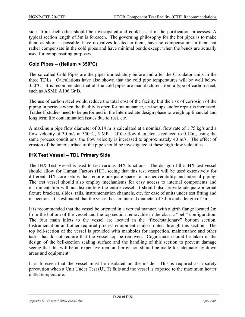
NGNP-CTF 20-CTF HTGR Component Test Facility (CTF) Recommendations
D-20 of D-51 Appendix D - Concept1 detail-FINAL.doc April 2008
sides from each other should be investigated and could assist in the purification processes. A typical section length of 5m is foreseen. The governing philosophy for the hot pipes is to make them as short as possible, have no valves located in them, have no compensators in them but rather compensate in the cold pipes and have minimal bends except when the bends are actually used for compensating purposes.
Cold Pipes – (Helium < 350°C)
The so-called Cold Pipes are the pipes immediately before and after the Circulator units in the three TDLs. Calculations have also shown that the cold pipe temperatures will be well below 350°C. It is recommended that all the cold pipes are manufactured from a type of carbon steel, such as ASME A106 Gr B.
The use of carbon steel would reduce the total cost of the facility but the risk of corrosion of the piping in periods when the facility is open for maintenance, test setups and/or repair is increased. Tradeoff studies need to be performed in the Intermediate design phase to weigh up financial and long term life contamination issues due to rust, etc.
A maximum pipe flow diameter of 0.14 m is calculated at a nominal flow rate of 1.75 kg/s and a flow velocity of 30 m/s at 350°C, 5 MPa. If the flow diameter is reduced to 0.12m, using the same process conditions, the flow velocity is increased to approximately 40 m/s. The effect of erosion of the inner surface of the pipe should be investigated at these high flow velocities.
IHX Test Vessel – TDL Primary Side
The IHX Test Vessel is used to test various IHX functions. The design of the IHX test vessel should allow for Human Factors (HF), seeing that this test vessel will be used extensively for different IHX core setups that require adequate space for maneuverability and internal piping. The test vessel should also employ mechanisms for easy access to internal components and instrumentation without dismantling the entire vessel. It should also provide adequate internal fixture brackets, slides, rails, instrumentation channels, etc. for ease of units under test fitting and inspection. It is estimated that the vessel has an internal diameter of 3.0m and a length of 5m.
It is recommended that the vessel be oriented in a vertical manner, with a girth flange located 2m from the bottom of the vessel and the top section removable in the classic “bell” configuration. The four main inlets to the vessel are located in the “fixed/stationary” bottom section. Instrumentation and other required process equipment is also routed through this section. The top bell-section of the vessel is provided with manholes for inspection, maintenance and other tasks that do not require that the vessel top be removed. Cognizance should be taken in the design of the bell-section sealing surface and the handling of this section to prevent damage seeing that this will be an expensive item and provision should be made for adequate lay-down areas and equipment.
It is foreseen that the vessel must be insulated on the inside. This is required as a safety precaution when a Unit Under Test (UUT) fails and the vessel is exposed to the maximum heater outlet temperature.

NGNP-CTF 20-CTF HTGR Component Test Facility (CTF) Recommendations
D-21 of D-51 Appendix D - Concept1 detail-FINAL.doc April 2008
Test Station Test Vessel – TDL Primary Side
The IHX Test Station is utilized to test various components and sub systems such as valves, hot ducting, process heat exchangers and the like. The same philosophy used for the IHX Test Vessel is employed here. It is proposed that the test Station vessel has an internal diameter of 3.0m and a length of 5m.
1.6.4 Heat Transfer Components
Recuperator Unit – TDL Primary Side
The recuperator unit in all three TDLs is used to recover the energy input of the Heater units after the UUTs. To ensure that the process loops’ design integrity is one level higher than the units under test, requires that conventional type recuperators be used. Since various tests are performed at different flow rates and pressures a detailed investigation is needed to determine whether a single recuperator sized for the worst case requirement would be able to operate at a reasonable effectiveness at off design conditions.
In the event where tests are conducted and little or no heat is rejected by the test components such as valves tests and hot ducts and insulation tests, the inlet temperature of the recuperator can reach 950°C. It is recommended to use a COTS conventional type recuperator to ensure that the reliability of the loop is a level higher than that of the test components.
It should be investigated whether it would be possible to use a Helical Tubular Heat Exchanger. The tubular concept was developed and qualified in Germany for the Coal Gasification process coupled with a HTR, where the inlet temperature was 950°C and the mass flow rate approximately 3 kg/s. The operating pressure was significantly lower at 4000 kPa but this should have a negligible effect on the heat transfer capabilities.
The maximum possible heat transfer is approximately 6.3MW assuming a conservative effectiveness of 80%. The maximum required flow rate in the loop is 1.75 kg/s. A first order estimate of the size of the recuperator is approximately a diameter of 2.5m x 12m length.
Another possibility would be to use a Helical Tubular Exchanger in conjunction with a compact heat exchanger. The Helical Tubular Exchanger is used to recuperate the high temperature portion of energy whilst the compact heat exchanger exchanges the lower temperature heat. This should reduce the overall size of the recuperator section with associated savings on the required pressure vessel as well.

NGNP-CTF 20-CTF HTGR Component Test Facility (CTF) Recommendations
D-22 of D-51 Appendix D - Concept1 detail-FINAL.doc April 2008
Recuperator Unit – TDL Secondary Side
The secondary side recuperator of the TDL loop will be a similar design to the TDL primary side recuperator. This recuperator is significantly smaller and the required duty is approximately 3.7 MW with an effectiveness (assumed) of 80%. The maximum required flow rate in the loop is 1.75 kg/s. A first order estimate of the size of the recuperator is approximately a diameter of 2.0m x 8m length. A similar approach to that of the TDL Primary Side recuperator can be followed using a Helical Tubular Exchanger in conjunction with a compact heat exchanger.
Recuperator Unit – CQL Primary Side
The primary side recuperator of the CQL loop will be a similar design to the TDL primary side recuperator. The recuperator is slightly bigger and the required duty is approximately 7.8 MW with an effectiveness (assumed) of 80%. The maximum required flow rate in the loop is 5.25 kg/s. A first order estimate of the size of the recuperator is approximately a diameter of 2.0m x 15m length. A similar approach to that of the TDL Primary Side recuperator can be followed using a Helical Tubular Exchanger in conjunction with a compact heat exchanger.
Recuperator Unit – CQL Secondary Side
The secondary side recuperator of the CQL loop will be of similar design to that of the CQL Primary Side recuperator. The recuperator is significantly bigger and the required duty is approximately 13 MW with an effectiveness (assumed) of 80%. The maximum required flow rate in the loop is 5.25 kg/s. A first order estimate of the size of the recuperator is approximately a diameter of 3.0m x 18m length. A similar approach to that of the TDL Primary Side recuperator can be followed using a Helical Tubular Exchanger in conjunction with a compact heat exchanger.
1.6.5 Heat Sink Requirements
Cooler – TDL Primary Side
The cooler is used to cool the helium prior to entering the circulator. The circulator inlet temperature is conservatively limited to 80°C. The maximum helium temperature at the inlet to the cooler (without gas bypass from the surge control valve) is approximately 260°C. The required maximum duty of the cooler at a nominal flow rate of 1.75 kg/s is 1.6 MW. It is suggested that either an air-cooler or shell-and-tube cooler be used for this application. An air cooler requires a variable speed drive to control the outlet temperature. The shell-and-tube heat exchanger performs better when sudden temperature transients are present due to the thermal inertia of cooler and coolant. If a shell-and-tube unit is used, it is recommended that a water and ethylene glycol mixture be used. The use of a mixture of water and ethylene glycol would possibly require a closed circuit cooling tower. A maximum coolant flow rate of 20 – 25 kg/s is required to keep the water temperature below 50°C at the cooler outlet. The outlet temperature of the helium can then be regulated by using a coolant bypass and circulating loop.

NGNP-CTF 20-CTF HTGR Component Test Facility (CTF) Recommendations
D-23 of D-51 Appendix D - Concept1 detail-FINAL.doc April 2008
Cooler – TDL Secondary Side
The secondary side loop of the TDL requires that the fluid be cooled from 460°C to 80°C. The high inlet temperature requires the use of an Air-cooled Helium cooler. The required maximum duty of the cooler at a nominal flow rate of 1.15 kg/s is 2.5 MW. A first order estimate of the size of the cooler is approximately 4.0m x 4.0m x 0.5m. The cooler uses 4 axial flow fans to supply the required air flow rate of 60 kg/s.
Cooler – CQL Secondary Side
The secondary side circulator inlet temperature is also conservatively limited to 80°C. The maximum helium temperature at the inlet to the cooler (without gas bypass from the surge control valve) is approximately 185°C. The required maximum duty of the cooler at a nominal flow rate of 5.25 kg/s is 2.6 MW. A shell-and-tube cooler is recommended for this application, also with a water and ethylene glycol mixture as secondary coolant. A maximum coolant flow rate of 25 – 30 kg/s is required to keep the water temperature below 50°C at the cooler outlet.
Auxiliary Cooling System
An Auxiliary Cooling System is required for each TDL to supply cooled treated water to the helium coolers (if shell and tube coolers are used). The operation and reliability of the auxiliary cooling system is of utmost importance critical to avoid damage to the helium circulators. The auxiliary cooling system consists of the cooling tower, the water treatment and make up system, the cooling pumps and interconnecting pipe system.
� Cooling Tower
It is suggested that a closed circuit cooling tower be used to cool the fluid. The cooling fluid’s temperature before it enters the cooling tower circuit reaches a maximum temperature of approximately 50°C. The cooling tower cools the cooling fluid down to approximately 25°C. The maximum water temperature at the inlet to the heat exchanger is approximately 30°C.
� Cooling Pumps
The cooling pumps required in the auxiliary cooling system should supply the coolers with approximately 20 kg/s water. A single stage centrifugal pump is suggested with a 600 kPa pressure rise at the supplied flow rate. An additional pump is suggested for redundancy.
� Cooling System Piping
The cooling system piping comprises the piping between the cooling tower and Helium coolers. The minimum required pipe size is a 100 mm NB.
� Water Treatment System
The cooling water systems are an integral part of the process. The systems require proper chemical treatment for reliable plant operation. The typical problems associated with the cooling
NGNP-CTF 20-CTF HTGR Component Test Facility (CTF) Recommendations
D-24 of D-51 Appendix D - Concept1 detail-FINAL.doc April 2008
water systems include corrosion, scale, fouling and microbiological contamination. These problems contribute to other secondary problems with heat transfer abilities of components and ultimately performance degradation of the process.
Air-cooled Condenser
The air-cooled condenser forms part of the Steam Generator Tests. The details for the condenser will only be determined once the detail of the steam generator tests has been defined. The condenser will typically have a capacity of 15MW at 5kg/s.
1.6.6 Helium Inventory and Control System
The Helium Inventory System (HICS) has the main function to supply, extract and maintain Helium inventory within the process loops. The HICS should have the ability to either fill the system from bulk Helium containers or from the storage vessels located onsite. The system should be able to pump helium from the latter at a pressure lower than the process pressure to the process.
Components of the HICS
� Helium Storage Vessels
The helium storage vessels are used to store the process inventory during maintenance or repair periods when the complete inventory is not to be wasted. It is suggested that the storage vessels have the capacity to store the entire inventory of the process – primary and secondary loop. The entire inventory will be stored at an estimated pressure of 14000 kPa to reduce the required storage volume. The volume of the primary side and secondary side of the loop is approximately 200 – 300 m3. The total calculated volume of the storage tanks are 130 – 190 m3 at 14000 kPa. The storage vessels’ volume is currently limited to approximately 16 m3. In total 10 – 12 of these vessels are required to store the entire inventory. The vessels will have an approximate diameter of 1.5m and a length of 10m. Tradeoff studies need to be performed during the Preliminary design to determine the cost implication of investing in hardware such as the Helium Storage Vessels and the cost of loss-of-inventory.
� Inventory Transfer System
The inventory transfer system is utilized to transfer Helium from the bulk Helium containers and the storage tanks to the primary and secondary process loops and back. The system consists of isolation and control valves as well as a positive displacement compressor unit. The compressor unit is used to transfer the fluid when the pressure of the volume to which the fluid is transferred is higher than the system from which it is pumped. The size of the compressor is determined by the maximum pressure of the storage vessels and the time required to fully transport the inventory of the process. The different modes of the inventory transfer system are illustrated in Figure 9 through Figure 13. Figure 9 shows the process flow diagram when the loop is supplied with Helium when the pressure in the loop is higher than the pressure in the storage tanks. Figure 10 shows the process flow diagram when the loop is supplied with Helium when the pressure in the loop is lower than the pressure in the storage tanks and the compressor is not

NGNP-CTF 20-CTF HTGR Component Test Facility (CTF) Recommendations
D-25 of D-51 Appendix D - Concept1 detail-FINAL.doc April 2008
needed. Figure 11 and Figure 12 show the process flow diagram when the Helium is extracted from the loop when the pressure in the loop is 1) higher than the pressure in the storage tanks and the compressor is not needed and 2) lower than the pressure in the storage tanks and the compressor is needed to increase the pressure in the storage tanks.
Figure 13 shows the process flow diagram for the conditioning of the Low Pressure Vent tank, which can be utilized when a pipe break is simulated to suddenly extract the inventory. The pressure in the LP Vent tank is reduced significantly to simulate a postulated pipe break scenario. The LP Vent tank should however be located close to the loop where the pipe break scenario is simulated to reduce the inertia effects of the gas.
Helium Tube Trailer
16 m³ 16 m³ 16 m³
LP Vent Tank
Vacuum Pump
HVAC
Figure 9: Helium Injection into System When the Process Pressure is Higher than the Storage Tank Pressure

NGNP-CTF 20-CTF HTGR Component Test Facility (CTF) Recommendations
D-26 of D-51 Appendix D - Concept1 detail-FINAL.doc April 2008
Helium Tube Trailer
16 m³ 16 m³ 16 m³
LP Vent Tank
Vacuum Pump
HVAC
Figure 10: Helium Injection into System When the Process Pressure is Lower than the Storage Tank Pressure
Helium Tube Trailer
16 m³ 16 m³ 16 m³
LP Vent Tank
Vacuum Pump
HVAC
Figure 11: Helium Extraction from the System When the Process Pressure is Higher than the Storage Tank Pressure

NGNP-CTF 20-CTF HTGR Component Test Facility (CTF) Recommendations
D-27 of D-51 Appendix D - Concept1 detail-FINAL.doc April 2008
Helium Tube Trailer
16 m³ 16 m³ 16 m³
LP Vent Tank
Vacuum Pump
HVAC
Figure 12: Helium Extraction from the System When the Process Pressure is Lower than the Storage Tank Pressure
Helium Tube Trailer
16 m³ 16 m³ 16 m³
LP Vent Tank
Vacuum Pump
HVAC
Figure 13: Conditioning of the Low Pressure Vent Tank

NGNP-CTF 20-CTF HTGR Component Test Facility (CTF) Recommendations
D-28 of D-51 Appendix D - Concept1 detail-FINAL.doc April 2008
� Vacuum System
The vacuum system is used to evacuate the process loop before Helium gas is introduced into the loop. The vacuum system is also used to reduce the pressure of the low pressure vent tank that is used for specified tests.
1.6.7 Helium Purification System (HPS)
Purification Requirements
It is envisaged that the general purification requirements for the Component Test Facility would be to remove H2 and CO from each of the primary and secondary loops to restrict the deposition of carbon on metallic surfaces, particularly ferritic steels at high temperatures (�500°C). The moisture content in the primary loop in particular, must be removed as it will react with the dust from the dust generators to form H2 and CO2. Residual oxygen from air after purging will also react with the dust from the dust generators to form CO and CO2.
Water and carbon dioxide will also be removed and be kept under the allowable limits (to be specified). It is expected that a large amount of impurities would be present after initial evacuation. It is further suggested that the dust from the dust filters be heated and purged separately to reduce the amount of moisture and oxygen present before operation.
Process Description
A Pressure Swing Adsorption (PSA) is used to remove impurities from the helium stream. A molecular sieve membrane or packed bed is used at high pressures and low temperatures to adsorb H2O and CO2. The packed bed or membrane becomes saturated after a period of time, and therefore needs to be regenerated. The regeneration process consists of blowing pure helium at elevated temperatures and low pressures in the reverse direction of the main process, whereby the impurities are removed from the molecular sieve. Since there will be no radioactive isotopes such as 14C or 3H the regeneration gas can simply be blown to the off-gas. The H2 and CO must however first be converted for the adsorption process in the molecular sieve.
Components of the HPS
� Dust Filters
Since there will be dust generators, a filter or cyclone will be required to remove dust that enters the HPS. This will be necessary to ensure that the packed beds which remove impurities from the gas stream function as desired. Because of the potentially large amounts of dust generated, it is suggested that the gross amount be filtered with a cyclone or pre-filter followed by fine dust filters. The pre-filter will enhance the efficiency and operable life of the fine dust filters.

NGNP-CTF 20-CTF HTGR Component Test Facility (CTF) Recommendations
D-29 of D-51 Appendix D - Concept1 detail-FINAL.doc April 2008
� Copper Oxide Catalytic Converter
The copper oxide catalytic converter oxidizes H2 and CO so that it can be adsorbed in the molecular sieve. The CuO beds require a temperature of approximately 210°C with an oxygen supply to regenerate the bed after a period of oxidizing the CO and H2.
� Coolers
After the H2 has been oxidized to H2O in the CuO beds, it is recuperated and cooled using the feed from the loop, after which it is further cooled using a chilled water heat exchanger. This will ensure that most of the water is condensed, and also serves as a cooling medium for the gas stream for the adsorption of the impurities in the molecular sieve.
� Water Coalescer
A water coalescer is installed after the coolers to remove the water from the gas stream. This is necessary since water ingress in the molecular sieve will greatly reduce the adsorption capacity.
� Molecular Sieve
The molecular sieve will remove the remaining H2O and CO2 from the helium stream. Two, type 13X molecular sieves with an effective pore size of 1nm are suggested in parallel. While one is used to adsorb the impurities, the other is regenerated. The molecular sieve sizing will depend on the amount of impurities remaining in the system after evacuation and purging.
� Circulators
If the HPS is to be used to remove impurities before operation a circulator will be required in parallel with a valve to pre-circulate the helium. During normal operation a control valve will be used to control the amount of flow through the HPS due to the differential pressure.
1.6.8 Control and Instrumentation
The instrumentation requirements of CTF Concept 1 will be provided in a summary of the different types and requirements as per each separate process loop, while general requirements and recommendations for the Control & Instrumentation philosophy will be presented below.
General Requirements
The following is a list of general requirements and/or recommendations for the CTF Instrumentation and Control, and is applicable to the TDLs as well as the CQL.
All instrumentation should be categorized as being part of either plant protection, controllability or performance verification instrumentation. A clear distinction among these should therefore prevent that performance verification instrumentation be used for controllability or equipment protection purposes and assure that Intellectual Property associated with Technology Development is protected.

NGNP-CTF 20-CTF HTGR Component Test Facility (CTF) Recommendations
D-30 of D-51 Appendix D - Concept1 detail-FINAL.doc April 2008
These levels of categorization should then also be used to determine their robustness as well as accuracy and traceability to international standards. It is also suggested to have a dedicated Data Acquisition System (DAQ) for each of these categories, which could assist in plant operability by a single dedicated team while ensuring protection of intellectual property in the form of performance indicators.
Some of the major control items on the CTF loops include, but are not limited to the following:
� Mass flow rate control by varying the circulator drive speed with a VSD � Circulator surge control by means of a circulator bypass loop � Heater outlet temperature control with thyristor control on the heating elements � Operating and position feedback on valves (typically in HICS, HPS…) � Start-stop on all pumps, compressors, vacuum pumps. � Helium Inventory Control � Controllability of gas analyzer (valves, sampling pumps)
Data logging capability should at least have the following characteristics:
� The scan rate should be determined by user requirements and previous test facility experience. � Designed in such a way to allow for easy addition of data channels � High temperature system temperature measurements should be performed with at least 3 – 4
instruments in close vicinity, and should make use of a thermowell with a very low thermal inertia.
� All pressure measurements should use pressure averaging with at least 3 to 4 instruments � All instrumentation penetrations should be provided through fixed sections of the appropriate
vessels and provision should be made for termination of all necessary instrumentation in the inside of the vessels.
Care should be taken to install and position instrumentation (especially for performance verification) in easily accessible places, with easy replacement as a high priority.
Input and Output Channels
Table 10 gives an indication of the minimum required number of output channels. These outputs should serve as the minimum number of required measurements for Plant Protection, Plant Controllability and Performance Verification. Ultimately the entity which uses the facility to test their respective components should give an indication of what their specific needs are. Provision should also be made to have available open channels already routed to field termination points in the event of additional outputs required by the Test Entity.

NGNP-CTF 20-CTF HTGR Component Test Facility (CTF) Recommendations
D-31 of D-51 Appendix D - Concept1 detail-FINAL.doc April 2008
Table 10: Minimum Required Number of Outputs for Concept 1
Description T P �P Mass flow � / � Leak Rate Gas Analyzer Other TDL 1 Primary Loop Heater 20 - 1 - - - - - Piping 12 10 - 5 10 - - - Test station vessel 25 - 3 - 25 5 5 IHX test vessel 50 - 3 - 50 5
5 5
Dust generator - - 1 - - - - - Filtration station - - 1 - - - - - Recuperator 16 - 2 - - - - - Cooler 4 - 1 - - - - - Circulator 8 - 2 - - - - 10 Secondary Loop Test station vessel 25 - 3 - 25 5 5 5 Recuperator 16 - 2 - - - - - Cooler 4 - 1 - - - - - Circulator 8 - 2 - - - - 10 TDL 2 Primary Loop Heater 20 - 1 - - - - - Piping 12 10 - 5 10 - - - IHX test vessel 50 - 3 - 50 5 5 Recuperator 16 - 2 - - - - - Cooler 4 - 1 - - - - - Circulator 8 - 2 - - - - 10 Secondary Loop Recuperator 16 - 2 - - - - - Cooler 4 - 1 - - - - - Circulator 8 - 2 - - - - 10 TDL 3 Primary Loop Heater 20 - 1 - - - - - Piping 12 10 - 5 10 - - - Test Station Vessel 50 - 3 - 50 5 5
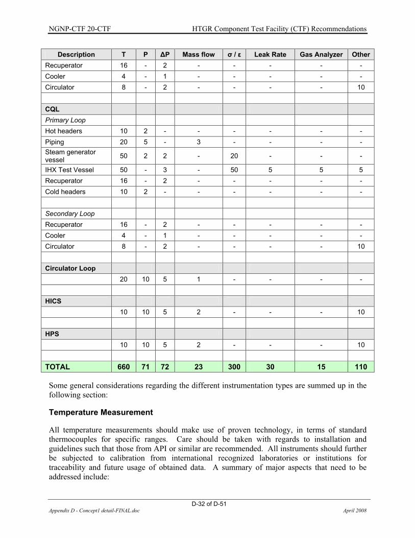
NGNP-CTF 20-CTF HTGR Component Test Facility (CTF) Recommendations
D-32 of D-51 Appendix D - Concept1 detail-FINAL.doc April 2008
Description T P �P Mass flow � / � Leak Rate Gas Analyzer Other Recuperator 16 - 2 - - - - - Cooler 4 - 1 - - - - - Circulator 8 - 2 - - - - 10 CQL Primary Loop Hot headers 10 2 - - - - - - Piping 20 5 - 3 - - - - Steam generator vessel 50 2 2 - 20 - - -
IHX Test Vessel 50 - 3 - 50 5 5 5 Recuperator 16 - 2 - - - - - Cold headers 10 2 - - - - - - Secondary Loop Recuperator 16 - 2 - - - - - Cooler 4 - 1 - - - - - Circulator 8 - 2 - - - - 10 Circulator Loop 20 10 5 1 - - - - HICS 10 10 5 2 - - - 10 HPS 10 10 5 2 - - - 10
TOTAL 660 71 72 23 300 30 15 110
Some general considerations regarding the different instrumentation types are summed up in the following section:
Temperature Measurement
All temperature measurements should make use of proven technology, in terms of standard thermocouples for specific ranges. Care should be taken with regards to installation and guidelines such that those from API or similar are recommended. All instruments should further be subjected to calibration from international recognized laboratories or institutions for traceability and future usage of obtained data. A summary of major aspects that need to be addressed include:

NGNP-CTF 20-CTF HTGR Component Test Facility (CTF) Recommendations
D-33 of D-51 Appendix D - Concept1 detail-FINAL.doc April 2008
� Detailed selection of correct instruments for measurement range and application � Calibration requirements and plan � Installation requirements and guidelines � Accessibility and re-calibration possibilities
Pressure Measurement
Pressure measurements should again make use of high integrity, proven instrumentation with specific attention to be given to ranges and the application of hot measurements.
Mass flow Measurement
Mass flow measurements are anticipated to be measured at the colder location of the loop, with a maximum temperature of 650°C for the mixing chamber tests. With this high temperature it is anticipated that standard pressure drop measurement installations will be used, with additional care for high temperature differential pressure measurement. A further investigation with regards to different or newly developed technology is still recommended.
Strain Measurement
Apart from the various strain measurements on the units under test, it also envisaged that the plant should have various measurements at critical locations. These should typically be high temperature strain gauges in excess of 1000°C from manufacturers such as Strainsense (www.strainsense.co.uk) or HPI (www.hitecprod.com).
Leak Rate Monitoring
Leak rate monitoring should be provided in at least mobile and stationary units. These different systems are needed for both leak rates monitoring on the complete plant as well dedicated installed systems where leak rates are needed to be measured on components under test. Specific means of monitoring still need to be investigated, depending on the anticipated rates and additional constraints. Typical methods include:
� Mechanical effects � Pressure decrease � Tracer gas measurement
1.6.9 Circulator
The circulator in this loop will be a UUT. Full scale circulator tests are required to verify their performance at design conditions. The design of the loop makes provision for a circulator up to 15MWt. The maximum flow rate is limited to 160 kg/s.
The following is a short write-up by one of the leading South African turbo machinery consultants and serves as motivation for employing a full scale circulator loop.
“The characteristics of helium as process gas present a very different set of constraints for the design of Turbo machinery. Firstly the sonic velocity in helium is approximately 3 times higher

NGNP-CTF 20-CTF HTGR Component Test Facility (CTF) Recommendations
D-34 of D-51 Appendix D - Concept1 detail-FINAL.doc April 2008
than that of conventional fluids used as process fluid. Generally the tip speeds of industrial Turbo machinery is limited to velocities well below the sonic velocity i.e. Mach < 1. With Helium as operating fluid the rotating speed is no longer limited by the mechanical design. The rotating speed is governed by the maximum allowable material stress due to the centrifugal load. Secondly the specified heat capacitance of helium is approximately five times higher than air. Therefore the pressure & temperature rise that can be achieved per stage is very small.
High pressure helium Turbo machinery presents an even more challenging set of design requirements. In order to reduce the weight of the nuclear grade pressure boundary, the rotational speeds are increased to the mechanical limit of the rotating component material allowable stress limit. Even at high rotating speeds and pressure levels only moderate Reynolds numbers can be achieved. Experience has shown that the efficiency of the turbo machine as well as the performance of the individual gas path components is very dependant on the Reynolds number.
Scaled testing of Helium Turbo machinery by making use of geometrical scaling laws is difficult to achieve in practice. Ideally testing should be carried out at similar Reynolds and Mach numbers. Due to the fact that the rotational speed and pressure for the full scale model is set at high levels for the full scale design, half scale testing is not practical for the following reasons:
Doubling the operational rotational speed will require allowable stress limits well above the current state of the art material limits.
An increased density (pressure) to maintain testing similarity requires an even heavier pressure boundary, offsetting the benefit of scaled testing. Increasing the pressure also affects the pressure balancing of the rotating train.
To maintain similarity at part load presents an even bigger challenge due to the fact that the flow will not be fully turbulent.
The objectives of the full scale helium loop test are to verify the predicted compressor performance, stability of operation and reliability at both the design and the part load operations. Therefore the Helium Loop Test should confirm both the steady state and transient characteristics of the turbo compressor.
The material stress intensity due to gas path component vibration is strongly dependant on the inlet pressure. The inlet pressure should be maintained at a constant level during steady state and transient testing to make the evaluation of the test results easier. It is proposed that additional helium gas be supplied to the closed loop by means of an inventory control system, to maintain a constant pressure level at the compressor inlet. This should serve as a design criterion for the inventory control system.
Presently very limited experience exists related to surge protection of helium gas turbo compressors. Ideally the turbo compressor should be relieved from the surge condition as soon as possible. The response of the compressor bypass valve should be confirmed as an adequate surge protection system to ensure long term reliability. The suitability & reliability of surge monitoring instrumentation in a high pressure helium atmosphere should be confirmed.

NGNP-CTF 20-CTF HTGR Component Test Facility (CTF) Recommendations
D-35 of D-51 Appendix D - Concept1 detail-FINAL.doc April 2008
In conclusion it is recommended that a full scale helium blower loop test be considered to verify various characteristics and aspects of the turbo compressor envisaged for the NGNP to ensure long term reliability.”
1.6.10 Piping
The piping in the circulator loop is required to handle a maximum temperature of 590°C. The option therefore exists for the use of a single (or multiple) stainless steel pipe(s), or a hot pipe design. To limit the maximum flow velocity in the pipe to 80 m/s, a pipe with a flow diameter of 0.7m is required at 590°C, 9 MPa.
1.6.11 Cooler
The cooler in the circulator loop should be able to extract the heat in the fluid produced by the specific circulator. Since various circulators will be tested, the cooler will be required to operate at various operating points. It should therefore be investigated whether a single unit or 2 and more in parallel is more suited to cover the entire operating range specified for the loop once more information on the circulators is available.

NG
NP-
CTF
20-
CTF
H
TGR
Com
pone
nt T
est F
acili
ty (C
TF) R
ecom
men
datio
ns
D-3
6 of
D-5
1
Appe
ndix
D -
Con
cept
1 de
tail-
FIN
AL.d
oc
Apri
l 200
8
2.1
ENER
GY
BA
LAN
CES
IHX
Ves
sel
Test
Sta
tion:
Rec
uper
ator
Rec
uper
ator
Coo
ling
gas
IHX
C&
I
Dus
t Gen
erat
or
Test
Sta
tion
Inst
rum
enta
tion
Req
uire
men
ts: T
estin
g of
-Hot
circ
uit p
ipin
g-I
sola
tion
valv
es-M
ixin
g ch
ambe
rs-I
HX
LS
Test
Sta
tion
Ves
sel
Prim
ary
side
: H
eliu
m
Sec
onda
ry s
ide
: Hel
ium
IHX
Vess
el
Rec
uper
ator
Rec
uper
ator
Coo
ling
gas
IHX
C&
I
Prim
ary
side
: H
eliu
m
Sec
onda
ry s
ide
: He-
N2
/ O
ther
flui
ds
Test
Sta
tion
Rec
uper
ator
Coo
ling
gas
C&I
Prim
ary
side
: H
eliu
m
TDL
#1
TDL
#2
TDL
#3
TDL
#1
TDL
#2
TDL
#3
Prim
ary
side
: H
eliu
m
From NGNP
To CQL
To CQL
From
CQ
L
From
CQ
L
From
CQ
L
Test
ves
sel f
or
larg
e co
mpo
nent
qu
alifi
catio
n
TO NGNP
Rec
uper
ator
Larg
e sc
ale
IHX
te
stin
g
To CQL
Ste
am G
ener
ator
Ves
sel
Feed
Pre
-hea
ter
Air
Coo
led
Con
dens
ers
Circ
ulat
or T
est l
oop
From HICS
From HPS
Filte
r sta
tion
H 1
.1H 3
.1
H 2
.1
Rec
uper
ator
Air C
oole
d C
onde
nser
s
C 1
.1
RX
1.1
TS 1
.1D
G 1
.1IH
X 1
.1FS
1.1
CL
1.1
TS 1
.2
Hea
ter
RX
1.2
C 1
.2
RX
3.1
C3.
1
CL
1.2
CL
3.1
TS3.
1
C2.
1
C2.
2
CL
2.1
IHX
2.1
CL
2.2
RX
2.1
RX
2.2
IHX
4.1R
X4.
1R
X4.
2
CL
4.2
SG
4.1
CL
4.1
C5.
1
CL
5.1
LP T
ank
LP2.
2
? H
ICS
? LP
ven
t ves
sel
? H
PS
? P
roce
ss C
ontro
l?
Wat
er tr
eatm
entp
lant
? C
ompr
esse
d ai
r sys
tem
s
? Te
st s
peci
fic in
stru
men
tatio
n
? V
& V
inst
rum
enta
tion
AC
1.1
Seco
ndar
y si
de: H
eliu
m
Nom
encl
atur
e:
TDL:
Tec
hnol
ogy
deve
lopm
ent l
oop
CQ
L: C
ompo
nent
qua
lific
atio
n lo
opH
: Hea
ter
IHX
: Int
erm
edia
te h
eat e
xcha
nger
RX:
Rec
uper
ator
C: C
ircul
ator
CL:
Coo
ler
SG
: Ste
am g
ener
ator
TS: T
est s
tatio
nLP
: Low
pre
ssur
e ve
nt ta
nkA
C: A
ir co
oler
DG
: Dus
t gen
erat
orFS
: Filt
ratio
n st
atio
n
C 4
.2
12
34
56
78
910
1112
12
34
56
78
910
1112
ABCDEFGHI
ABCDEFGHI
NO
TES:
1.
REF
EREN
CE
DR
AWIN
GS
REV
ISIO
NS
ISSU
EDR
EV.
REA
SON
FO
R R
EVIS
ION
DAT
EBY
AD
RAF
TD
ate
PRO
JEC
T
[Nam
e]
[Dra
win
g Ti
tle]
[Dra
win
g N
umbe
r]
TITL
E
DO
CU
MEN
T N
UM
BER
Aux
iliar
y Sy
stem
s(N
OTE
: Eac
h Te
st L
oop
to h
ave
its o
wn
set o
f aux
iliar
y sy
stem
s, n
o sh
arin
g of
sup
port
syst
ems)
Con
trol
& In
stru
men
tatio
n(N
OTE
: Eac
h Te
st lo
op w
ill h
ave
own
set o
f con
trol &
inst
rum
enta
tion
syst
ems,
no
shar
ing
of s
uppo
rt sy
stem
s)
Lege
nd:
Hea
t tra
nsfe
r co
mpo
nent
/ R
ecup
erat
or /
IHX
Circ
ulat
or
Coo
ler H
X
Clo
sed
circ
uit
cool
ing
tow
er /
air
cool
ed c
onde
nser
Pres
sure
ves
sel /
Te
st v
esse
l
Air C
oole
r
Ele
ctric
re
sist
ance
he
atin
g
Bas
ic L
ayou
t CTF
C
once
pt 1

NG
NP-
CTF
20-
CTF
H
TGR
Com
pone
nt T
est F
acili
ty (C
TF) R
ecom
men
datio
ns
D-3
7 of
D-5
1
Appe
ndix
D -
Con
cept
1 de
tail-
FIN
AL.d
oc
Apri
l 200
8
IHX
Ves
sel
Test
Sta
tion:
Rec
uper
ator
Rec
uper
ator
Coo
ling
gas
IHX
C&
I
Dus
t Gen
erat
or
Test
Sta
tion
Inst
rum
enta
tion
Req
uire
men
ts: T
estin
g of
-Hot
circ
uit p
ipin
g-I
sola
tion
valv
es-M
ixin
g ch
ambe
rs-I
HX
LS
Test
Sta
tion
Ves
sel
Prim
ary
side
: H
eliu
m
Sec
onda
ry s
ide
: Hel
ium
IHX
Ves
sel
Rec
uper
ator
Rec
uper
ator
Coo
ling
gas
IHX
C&
I
Prim
ary
side
: H
eliu
m
Sec
onda
ry s
ide
: He-
N2
/ O
ther
flui
ds
Test
Sta
tion
Rec
uper
ator
Coo
ling
gas
C&I
Prim
ary
side
: H
eliu
m
TDL
#1
TDL
#2
TDL
#3
TDL
#1
TDL
#2
TDL
#3
Prim
ary
side
: H
eliu
m
From NGNP
To CQL
To CQL
From
CQ
L
From
CQ
L
From
CQ
L
Test
ves
sel f
or
larg
e co
mpo
nent
qu
alifi
catio
n
TO NGNP
Rec
uper
ator
Larg
e sc
ale
IHX
te
stin
g
To CQL
Ste
am G
ener
ator
Ves
sel
Feed
Pre
-hea
ter
Air
Coo
led
Con
dens
ers
Circ
ulat
or T
est l
oop
From HICS
From HPS
Filte
r sta
tion
H 1
.1H 3
.1
H 2
.1
Rec
uper
ator
Air
Coo
led
Con
dens
ers
C 1
.1
RX
1.1
TS 1
.1D
G 1
.1IH
X 1
.1FS
1.1
CL
1.1
TS 1
.2
Hea
ter
RX
1.2
C 1
.2
RX
3.1
C3.
1
CL
1.2
CL
3.1
TS3.
1
C2.
1
C2.
2
CL
2.1
IHX
2.1
CL
2.2
RX
2.1
RX
2.2
IHX
4.1R
X4.
1R
X4.
2
CL
4.2
SG
4.1
CL
4.1
C5.
1
CL
5.1
LP T
ank
LP2.
2
? H
ICS
? LP
ven
t ves
sel
? H
PS
? P
roce
ss C
ontro
l?
Wat
er tr
eatm
entp
lant
? C
ompr
esse
d ai
r sys
tem
s
? Te
st s
peci
fic in
stru
men
tatio
n
? V
& V
inst
rum
enta
tion
AC
1.1
Sec
onda
ry s
ide:
Hel
ium
Nom
encl
atur
e:
TDL:
Tec
hnol
ogy
deve
lopm
ent l
oop
CQ
L: C
ompo
nent
qua
lific
atio
n lo
opH
: Hea
ter
IHX:
Inte
rmed
iate
hea
t exc
hang
erR
X: R
ecup
erat
orC
: Circ
ulat
orC
L: C
oole
rSG
: Ste
am g
ener
ator
TS: T
est s
tatio
nLP
: Low
pre
ssur
e ve
nt ta
nkAC
: Air
cool
erD
G: D
ust g
ener
ator
FS: F
iltra
tion
stat
ion
C 4
.2
12
34
56
78
910
1112
12
34
56
78
910
1112
ABCDEFGHI
ABCDEFGHI
NO
TES:
1.
REF
EREN
CE
DR
AWIN
GS
REV
ISIO
NS
ISSU
EDR
EV.
REA
SON
FO
R R
EVIS
ION
DAT
EBY
AD
RAF
TD
ate
PRO
JEC
T
[Nam
e]
[Dra
win
g Ti
tle]
[Dra
win
g N
umbe
r]
TITL
E
DO
CU
MEN
T N
UM
BER
Aux
iliar
y Sy
stem
s(N
OTE
: Eac
h Te
st L
oop
to h
ave
its o
wn
set o
f aux
iliar
y sy
stem
s, n
o sh
arin
g of
sup
port
syst
ems)
Con
trol
& In
stru
men
tatio
n(N
OTE
: Eac
h Te
st lo
op w
ill h
ave
own
set o
f con
trol &
inst
rum
enta
tion
syst
ems,
no
shar
ing
of s
uppo
rt sy
stem
s)
Lege
nd:
Hea
t tra
nsfe
r co
mpo
nent
/ R
ecup
erat
or /
IHX
Circ
ulat
or
Coo
ler H
X
Clo
sed
circ
uit
cool
ing
tow
er /
air
cool
ed c
onde
nser
Pre
ssur
e ve
ssel
/ Te
st v
esse
l
Air
Coo
ler
Elec
tric
resi
stan
ce
heat
ing
Test
Con
figur
atio
n:
IHX-
W_1
T: 6
24ºC
T: 9
50ºC
Q: 1
.9 M
W
T: 9
50ºC
T: 7
60ºC
T: 7
10ºC
T: 9
00ºC
Q: 1
.34
MW
T: 7
60ºC
m: 1
.15
kg/s
P:
9 M
Pa
T: 6
24ºC
T: 8
3ºC
T: 2
18ºC
Q: 3
.2 M
W
Eff:
0.8
T: 8
0ºC
Q: 0
.8 M
W
m: 1
.15
kg/s
P:
9 M
Pa
T: 9
00ºC
T: 2
70ºC
T: 7
36ºC
Q: 3
.7 M
W
Eff:
0.8
T: 8
0ºC
T: 8
3ºC
Q: 1
.1 M
W
m: 1
.108
kg/
s
m: 0
.042
kg/
s

NG
NP-
CTF
20-
CTF
H
TGR
Com
pone
nt T
est F
acili
ty (C
TF) R
ecom
men
datio
ns
D-3
8 of
D-5
1
Appe
ndix
D -
Con
cept
1 de
tail-
FIN
AL.d
oc
Apri
l 200
8
IHX
Ves
sel
Test
Sta
tion:
Rec
uper
ator
Rec
uper
ator
Coo
ling
gas
IHX
C&
I
Dus
t Gen
erat
or
Test
Sta
tion
Inst
rum
enta
tion
Req
uire
men
ts: T
estin
g of
-Hot
circ
uit p
ipin
g-I
sola
tion
valv
es-M
ixin
g ch
ambe
rs-I
HX
LS
Test
Sta
tion
Vess
elP
rimar
y si
de :
Hel
ium
Sec
onda
ry s
ide
: Hel
ium
IHX
Ves
sel
Rec
uper
ator
Rec
uper
ator
Coo
ling
gas
IHX
C&I
Prim
ary
side
: H
eliu
m
Sec
onda
ry s
ide
: He-
N2
/ O
ther
flui
ds
Test
Sta
tion
Rec
uper
ator
Coo
ling
gas
C&I
Prim
ary
side
: H
eliu
m
TDL
#1
TDL
#2
TDL
#3
TDL
#1
TDL
#2
TDL
#3
Prim
ary
side
: H
eliu
m
From NGNP
To CQL
To CQLFr
om C
QL
From
CQ
L
From
CQ
L
Test
ves
sel f
or
larg
e co
mpo
nent
qu
alifi
catio
n
TO NGNP
Rec
uper
ator
Larg
e sc
ale
IHX
te
stin
g
To CQL
Stea
m G
ener
ator
Ves
sel
Feed
Pre
-hea
ter
Air C
oole
d C
onde
nser
s
Circ
ulat
or T
est l
oop
From HICS
From HPS
Filte
r sta
tion
H 1
.1H 3
.1
H 2
.1
Rec
uper
ator
Air
Coo
led
Con
dens
ers
C 1
.1
RX
1.1
TS 1
.1D
G 1
.1IH
X 1
.1FS
1.1
CL
1.1
TS 1
.2
Hea
ter
RX
1.2
C 1
.2
RX
3.1
C3.
1
CL
1.2
CL
3.1
TS3.
1
C2.
1
C2.
2
CL
2.1
IHX
2.1
CL
2.2
RX
2.1
RX
2.2
IHX
4.1R
X4.
1R
X4.
2
CL
4.2
SG
4.1
CL
4.1
C5.
1
CL
5.1
LP T
ank
LP2.
2
? H
ICS
? LP
ven
t ves
sel
? H
PS
? P
roce
ss C
ontro
l?
Wat
er tr
eatm
entp
lant
? C
ompr
esse
d ai
r sys
tem
s
? Te
st s
peci
fic in
stru
men
tatio
n
? V
& V
inst
rum
enta
tion
AC
1.1
Sec
onda
ry s
ide:
Hel
ium
Nom
encl
atur
e:
TDL:
Tec
hnol
ogy
deve
lopm
ent l
oop
CQ
L: C
ompo
nent
qua
lific
atio
n lo
opH
: Hea
ter
IHX
: Int
erm
edia
te h
eat e
xcha
nger
RX
: Rec
uper
ator
C: C
ircul
ator
CL:
Coo
ler
SG
: Ste
am g
ener
ator
TS: T
est s
tatio
nLP
: Low
pre
ssur
e ve
nt ta
nkA
C: A
ir co
oler
DG
: Dus
t gen
erat
orFS
: Filt
ratio
n st
atio
n
C 4
.2
12
34
56
78
910
1112
12
34
56
78
910
1112
ABCDEFGHI
ABCDEFGHI
NO
TES:
1.
REF
EREN
CE
DR
AWIN
GS
REV
ISIO
NS
ISSU
EDR
EV.
REA
SON
FO
R R
EVIS
ION
DAT
EBY
AD
RAF
TD
ate
PRO
JEC
T
[Nam
e]
[Dra
win
g Ti
tle]
[Dra
win
g N
umbe
r]
TITL
E
DO
CU
MEN
T N
UM
BER
Aux
iliar
y Sy
stem
s(N
OTE
: Eac
h Te
st L
oop
to h
ave
its o
wn
set o
f aux
iliar
y sy
stem
s, n
o sh
arin
g of
sup
port
syst
ems)
Con
trol
& In
stru
men
tatio
n(N
OTE
: Eac
h Te
st lo
op w
ill h
ave
own
set o
f con
trol &
inst
rum
enta
tion
syst
ems,
no
shar
ing
of s
uppo
rt sy
stem
s)
Lege
nd:
Hea
t tra
nsfe
r co
mpo
nent
/ R
ecup
erat
or /
IHX
Circ
ulat
or
Coo
ler H
X
Clo
sed
circ
uit
cool
ing
tow
er /
air
cool
ed c
onde
nser
Pres
sure
ves
sel /
Te
st v
esse
l
Air C
oole
r
Elec
tric
resi
stan
ce
heat
ing
Test
Con
figur
atio
n:
IHX-
W_2
T: 2
86ºC
T: 7
60ºC
Q: 2
.3 M
W
T: 7
60ºC
T: 3
37ºC
T: 2
87ºC
T: 7
10ºC
Q: 2
.058
MW
T: 3
37ºC
T: 8
3ºC
T: 2
86ºC
T: 1
33ºC
Q: 1
MW
Eff:
0.8
P: 9
MPa
m
: 0.9
38 k
g/s
T: 8
0ºC
Q: 0
.25
MW
P: 9
MPa
m
: 0.9
38 k
g/s
T: 7
10ºC
T: 8
0ºC
T: 8
3ºC
Q: 1
.2 M
W
Eff:
0.8
m: 0
.46
kg/s
m: 0
.47
kg/s
T: 4
64ºC
T: 5
84ºC
Q: 1
.8 M
W

NG
NP-
CTF
20-
CTF
H
TGR
Com
pone
nt T
est F
acili
ty (C
TF) R
ecom
men
datio
ns
D-3
9 of
D-5
1
Appe
ndix
D -
Con
cept
1 de
tail-
FIN
AL.d
oc
Apri
l 200
8
IHX
Ves
sel
Test
Sta
tion:
Rec
uper
ator
Rec
uper
ator
Coo
ling
gas
IHX
C&
I
Dus
t Gen
erat
or
Test
Sta
tion
Inst
rum
enta
tion
Req
uire
men
ts: T
estin
g of
-Hot
circ
uit p
ipin
g-I
sola
tion
valv
es-M
ixin
g ch
ambe
rs-I
HX
LS
Test
Sta
tion
Ves
sel
Prim
ary
side
: H
eliu
m
Sec
onda
ry s
ide
: Hel
ium
IHX
Ves
sel
Rec
uper
ator
Rec
uper
ator
Coo
ling
gas
IHX
C&I
Prim
ary
side
: H
eliu
m
Sec
onda
ry s
ide
: He-
N2
/ O
ther
flui
ds
Test
Sta
tion
Rec
uper
ator
Coo
ling
gas
C&I
Prim
ary
side
: H
eliu
m
TDL
#1
TDL
#2
TDL
#3
TDL
#1
TDL
#2
TDL
#3
Prim
ary
side
: H
eliu
m
From NGNP
To CQL
To CQL
From
CQ
L
From
CQ
L
From
CQ
L
Test
ves
sel f
or
larg
e co
mpo
nent
qu
alifi
catio
n
TO NGNP
Rec
uper
ator
Larg
e sc
ale
IHX
te
stin
g
To CQL
Ste
am G
ener
ator
Ves
sel
Feed
Pre
-hea
ter
Air
Coo
led
Con
dens
ers
Circ
ulat
or T
est l
oop
From HICS
From HPS
Filte
r sta
tion
H 1
.1H 3
.1
H 2
.1
Rec
uper
ator
Air
Coo
led
Con
dens
ers
C 1
.1
RX
1.1
TS 1
.1D
G 1
.1IH
X 1
.1FS
1.1
CL
1.1
TS 1
.2
Hea
ter
RX
1.2
C 1
.2
RX
3.1
C3.
1
CL
1.2
CL
3.1
TS3.
1
C2.
1
C2.
2
CL
2.1
IHX
2.1
CL
2.2
RX
2.1
RX
2.2
IHX
4.1R
X4.
1R
X4.
2
CL
4.2
SG
4.1
CL
4.1
C5.
1
CL
5.1
LP T
ank
LP2.
2
? H
ICS
? LP
ven
t ves
sel
? H
PS
? P
roce
ss C
ontro
l?
Wat
er tr
eatm
entp
lant
? C
ompr
esse
d ai
r sys
tem
s
? Te
st s
peci
fic in
stru
men
tatio
n
? V
& V
inst
rum
enta
tion
AC
1.1
Sec
onda
ry s
ide:
Hel
ium
Nom
encl
atur
e:
TDL:
Tec
hnol
ogy
deve
lopm
ent l
oop
CQ
L: C
ompo
nent
qua
lific
atio
n lo
opH
: Hea
ter
IHX
: Int
erm
edia
te h
eat e
xcha
nger
RX
: Rec
uper
ator
C: C
ircul
ator
CL:
Coo
ler
SG
: Ste
am g
ener
ator
TS: T
est s
tatio
nLP
: Low
pre
ssur
e ve
nt ta
nkA
C: A
ir co
oler
DG
: Dus
t gen
erat
orFS
: Filt
ratio
n st
atio
n
C 4
.2
12
34
56
78
910
1112
12
34
56
78
910
1112
ABCDEFGHI
ABCDEFGHI
NO
TES:
1.
REF
EREN
CE
DR
AWIN
GS
REV
ISIO
NS
ISSU
EDR
EV.
REA
SON
FO
R R
EVIS
ION
DAT
EBY
AD
RAF
TD
ate
PRO
JEC
T
[Nam
e]
[Dra
win
g Ti
tle]
[Dra
win
g N
umbe
r]
TITL
E
DO
CU
MEN
T N
UM
BER
Aux
iliar
y Sy
stem
s(N
OTE
: Eac
h Te
st L
oop
to h
ave
its o
wn
set o
f aux
iliar
y sy
stem
s, n
o sh
arin
g of
sup
port
syst
ems)
Con
trol
& In
stru
men
tatio
n(N
OTE
: Eac
h Te
st lo
op w
ill h
ave
own
set o
f con
trol &
inst
rum
enta
tion
syst
ems,
no
shar
ing
of s
uppo
rt sy
stem
s)
Lege
nd:
Hea
t tra
nsfe
r co
mpo
nent
/ R
ecup
erat
or /
IHX
Circ
ulat
or
Coo
ler H
X
Clo
sed
circ
uit
cool
ing
tow
er /
air
cool
ed c
onde
nser
Pre
ssur
e ve
ssel
/ Te
st v
esse
l
Air
Coo
ler
Ele
ctric
re
sist
ance
he
atin
g
Test
Con
figur
atio
n:
IHX-
W_3
T: 7
76ºC
T: 9
50ºC
Q: 1
.0 M
W
T: 9
50ºC
T: 9
50ºC
m: 1
.15
kg/s
P:
9 M
Pa
T: 9
50ºC
T: 8
3ºC
T: 2
56ºC
T: 7
76ºC Q
: 4.1
MW
Eff:
0.8
T: 8
0ºC
Q: 1
MW

NG
NP-
CTF
20-
CTF
H
TGR
Com
pone
nt T
est F
acili
ty (C
TF) R
ecom
men
datio
ns
D-4
0 of
D-5
1
Appe
ndix
D -
Con
cept
1 de
tail-
FIN
AL.d
oc
Apri
l 200
8
IHX
Ves
sel
Test
Sta
tion:
Rec
uper
ator
Rec
uper
ator
Coo
ling
gas
IHX
C&
I
Dus
t Gen
erat
or
Test
Sta
tion
Inst
rum
enta
tion
Req
uire
men
ts: T
estin
g of
-Hot
circ
uit p
ipin
g-I
sola
tion
valv
es-M
ixin
g ch
ambe
rs-I
HX
LS
Test
Sta
tion
Vess
elP
rimar
y si
de :
Hel
ium
Sec
onda
ry s
ide
: Hel
ium
IHX
Ves
sel
Rec
uper
ator
Rec
uper
ator
Coo
ling
gas
IHX
C&I
Prim
ary
side
: H
eliu
m
Sec
onda
ry s
ide
: He-
N2
/ O
ther
flui
ds
Test
Sta
tion
Rec
uper
ator
Coo
ling
gas
C&I
Prim
ary
side
: H
eliu
m
TDL
#1
TDL
#2
TDL
#3
TDL
#1
TDL
#2
TDL
#3
Prim
ary
side
: H
eliu
m
From NGNP
To CQL
To CQL
From
CQ
L
From
CQ
L
From
CQ
L
Test
ves
sel f
or
larg
e co
mpo
nent
qu
alifi
catio
n
TO NGNP
Rec
uper
ator
Larg
e sc
ale
IHX
te
stin
g
To CQL
Stea
m G
ener
ator
Ves
sel
Feed
Pre
-hea
ter
Air C
oole
d C
onde
nser
s
Circ
ulat
or T
est l
oop
From HICS
From HPS
Filte
r sta
tion
H 1
.1H 3
.1
H 2
.1
Rec
uper
ator
Air
Coo
led
Con
dens
ers
C 1
.1
RX
1.1
TS 1
.1D
G 1
.1IH
X 1
.1FS
1.1
CL
1.1
TS 1
.2
Hea
ter
RX
1.2
C 1
.2
RX
3.1
C3.
1
CL
1.2
CL
3.1
TS3.
1
C2.
1
C2.
2
CL
2.1
IHX
2.1
CL
2.2
RX
2.1
RX
2.2
IHX
4.1R
X4.
1R
X4.
2
CL
4.2
SG
4.1
CL
4.1
C5.
1
CL
5.1
LP T
ank
LP2.
2
? H
ICS
? LP
ven
t ves
sel
? H
PS
? P
roce
ss C
ontro
l?
Wat
er tr
eatm
entp
lant
? C
ompr
esse
d ai
r sys
tem
s
? Te
st s
peci
fic in
stru
men
tatio
n
? V
& V
inst
rum
enta
tion
AC
1.1
Sec
onda
ry s
ide:
Hel
ium
Nom
encl
atur
e:
TDL:
Tec
hnol
ogy
deve
lopm
ent l
oop
CQ
L: C
ompo
nent
qua
lific
atio
n lo
opH
: Hea
ter
IHX
: Int
erm
edia
te h
eat e
xcha
nger
RX
: Rec
uper
ator
C: C
ircul
ator
CL:
Coo
ler
SG
: Ste
am g
ener
ator
TS: T
est s
tatio
nLP
: Low
pre
ssur
e ve
nt ta
nkA
C: A
ir co
oler
DG
: Dus
t gen
erat
orFS
: Filt
ratio
n st
atio
n
C 4
.2
12
34
56
78
910
1112
12
34
56
78
910
1112
ABCDEFGHI
ABCDEFGHI
NO
TES:
1.
REF
EREN
CE
DR
AWIN
GS
REV
ISIO
NS
ISSU
EDR
EV.
REA
SON
FO
R R
EVIS
ION
DAT
EBY
AD
RAF
TD
ate
PRO
JEC
T
[Nam
e]
[Dra
win
g Ti
tle]
[Dra
win
g N
umbe
r]
TITL
E
DO
CU
MEN
T N
UM
BER
Aux
iliar
y Sy
stem
s(N
OTE
: Eac
h Te
st L
oop
to h
ave
its o
wn
set o
f aux
iliar
y sy
stem
s, n
o sh
arin
g of
sup
port
syst
ems)
Con
trol
& In
stru
men
tatio
n(N
OTE
: Eac
h Te
st lo
op w
ill h
ave
own
set o
f con
trol &
inst
rum
enta
tion
syst
ems,
no
shar
ing
of s
uppo
rt sy
stem
s)
Lege
nd:
Hea
t tra
nsfe
r co
mpo
nent
/ R
ecup
erat
or /
IHX
Circ
ulat
or
Coo
ler H
X
Clo
sed
circ
uit
cool
ing
tow
er /
air
cool
ed c
onde
nser
Pre
ssur
e ve
ssel
/ Te
st v
esse
l
Air
Coo
ler
Elec
tric
resi
stan
ce
heat
ing
Test
Con
figur
atio
n:
IHX-
W_4
T: 6
24ºC
T: 7
60ºC
Q: 0
.7 M
W
T: 7
60ºC
P: 9
MP
a m
: 0.9
38 k
g/s
T: 7
60ºC
T: 7
60ºC
T: 8
0ºC
T: 8
3ºC
T: 6
24ºC
T: 2
18ºC
Q: 2
.6 M
W
Eff:
0.8
Q: 0
.7 M
W

NG
NP-
CTF
20-
CTF
H
TGR
Com
pone
nt T
est F
acili
ty (C
TF) R
ecom
men
datio
ns
D-4
1 of
D-5
1
Appe
ndix
D -
Con
cept
1 de
tail-
FIN
AL.d
oc
Apri
l 200
8
IHX
Ves
sel
Test
Sta
tion:
Rec
uper
ator
Rec
uper
ator
Coo
ling
gas
IHX
C&
I
Dus
t Gen
erat
or
Test
Sta
tion
Inst
rum
enta
tion
Req
uire
men
ts: T
estin
g of
-Hot
circ
uit p
ipin
g-I
sola
tion
valv
es-M
ixin
g ch
ambe
rs-I
HX
LS
Test
Sta
tion
Ves
sel
Prim
ary
side
: H
eliu
m
Sec
onda
ry s
ide
: Hel
ium
IHX
Ves
sel
Rec
uper
ator
Rec
uper
ator
Coo
ling
gas
IHX
C&I
Prim
ary
side
: H
eliu
m
Sec
onda
ry s
ide
: He-
N2
/ O
ther
flui
ds
Test
Sta
tion
Rec
uper
ator
Coo
ling
gas
C&I
Prim
ary
side
: H
eliu
m
TDL
#1
TDL
#2
TDL
#3
TDL
#1
TDL
#2
TDL
#3
Prim
ary
side
: H
eliu
m
From NGNP
To CQL
To CQL
From
CQ
L
From
CQ
L
From
CQ
L
Test
ves
sel f
or
larg
e co
mpo
nent
qu
alifi
catio
n
TO NGNP
Rec
uper
ator
Larg
e sc
ale
IHX
te
stin
g
To CQL
Stea
m G
ener
ator
Ves
sel
Feed
Pre
-hea
ter
Air C
oole
d C
onde
nser
s
Circ
ulat
or T
est l
oop
From HICS
From HPS
Filte
r sta
tion
H 1
.1H 3
.1
H 2
.1
Rec
uper
ator
Air
Coo
led
Con
dens
ers
C 1
.1
RX
1.1
TS 1
.1D
G 1
.1IH
X 1
.1FS
1.1
CL
1.1
TS 1
.2
Hea
ter
RX
1.2
C 1
.2
RX
3.1
C3.
1
CL
1.2
CL
3.1
TS3.
1
C2.
1
C2.
2
CL
2.1
IHX
2.1
CL
2.2
RX
2.1
RX
2.2
IHX
4.1R
X4.
1R
X4.
2
CL
4.2
SG
4.1
CL
4.1
C5.
1
CL
5.1
LP T
ank
LP2.
2
? H
ICS
? LP
ven
t ves
sel
? H
PS
? P
roce
ss C
ontro
l?
Wat
er tr
eatm
entp
lant
? C
ompr
esse
d ai
r sys
tem
s
? Te
st s
peci
fic in
stru
men
tatio
n
? V
& V
inst
rum
enta
tion
AC
1.1
Sec
onda
ry s
ide:
Hel
ium
Nom
encl
atur
e:
TDL:
Tec
hnol
ogy
deve
lopm
ent l
oop
CQ
L: C
ompo
nent
qua
lific
atio
n lo
opH
: Hea
ter
IHX
: Int
erm
edia
te h
eat e
xcha
nger
RX
: Rec
uper
ator
C: C
ircul
ator
CL:
Coo
ler
SG
: Ste
am g
ener
ator
TS: T
est s
tatio
nLP
: Low
pre
ssur
e ve
nt ta
nkA
C: A
ir co
oler
DG
: Dus
t gen
erat
orFS
: Filt
ratio
n st
atio
n
C 4
.2
12
34
56
78
910
1112
12
34
56
78
910
1112
ABCDEFGHI
ABCDEFGHI
NO
TES:
1.
REF
EREN
CE
DR
AWIN
GS
REV
ISIO
NS
ISSU
EDR
EV.
REA
SON
FO
R R
EVIS
ION
DAT
EBY
AD
RAF
TD
ate
PRO
JEC
T
[Nam
e]
[Dra
win
g Ti
tle]
[Dra
win
g N
umbe
r]
TITL
E
DO
CU
MEN
T N
UM
BER
Aux
iliar
y Sy
stem
s(N
OTE
: Eac
h Te
st L
oop
to h
ave
its o
wn
set o
f aux
iliar
y sy
stem
s, n
o sh
arin
g of
sup
port
syst
ems)
Con
trol
& In
stru
men
tatio
n(N
OTE
: Eac
h Te
st lo
op w
ill h
ave
own
set o
f con
trol &
inst
rum
enta
tion
syst
ems,
no
shar
ing
of s
uppo
rt sy
stem
s)
Lege
nd:
Hea
t tra
nsfe
r co
mpo
nent
/ R
ecup
erat
or /
IHX
Circ
ulat
or
Coo
ler H
X
Clo
sed
circ
uit
cool
ing
tow
er /
air
cool
ed c
onde
nser
Pre
ssur
e ve
ssel
/ Te
st v
esse
l
Air
Coo
ler
Elec
tric
resi
stan
ce
heat
ing
Test
Con
figur
atio
n:
IHX-
G_1
T: 9
50ºC
Q: 2
.7 M
W
T: 9
50ºC
T: 5
90ºC
T: 9
25ºC
T: 5
65ºC
P: 7
MPa
Q: 2
.14
MW
m: 1
.15k
g/s
T: 5
90ºC
T: 8
3ºC
T: 1
84ºC
T: 4
88ºC Q: 2
.4 M
W
T: 8
0ºC
Q: 0
.6 M
W
Eff:
0.93
5
Eff:
0.8
T: 4
88ºC
T: 4
21ºC
P: 7
MPa
Q: 3
.0 M
W
m: 1
.15k
g/s
T: 9
25ºC
T: 8
0ºC
T: 8
3ºC
m: 0
.86
kg/s
T: 7
56ºC
m: 0
.29
kg/s
Q: 2
.0 M
W
Eff:
0.8

NG
NP-
CTF
20-
CTF
H
TGR
Com
pone
nt T
est F
acili
ty (C
TF) R
ecom
men
datio
ns
D-4
2 of
D-5
1
Appe
ndix
D -
Con
cept
1 de
tail-
FIN
AL.d
oc
Apri
l 200
8
IHX
Ves
sel
Test
Sta
tion:
Rec
uper
ator
Rec
uper
ator
Coo
ling
gas
IHX
C&
I
Dus
t Gen
erat
or
Test
Sta
tion
Inst
rum
enta
tion
Req
uire
men
ts: T
estin
g of
-Hot
circ
uit p
ipin
g-I
sola
tion
valv
es-M
ixin
g ch
ambe
rs-I
HX
LS
Test
Sta
tion
Ves
sel
Prim
ary
side
: H
eliu
m
Sec
onda
ry s
ide
: Hel
ium
IHX
Ves
sel
Rec
uper
ator
Rec
uper
ator
Coo
ling
gas
IHX
C&
I
Prim
ary
side
: H
eliu
m
Sec
onda
ry s
ide
: He-
N2
/ O
ther
flui
ds
Test
Sta
tion
Rec
uper
ator
Coo
ling
gas
C&I
Prim
ary
side
: H
eliu
m
TDL
#1
TDL
#2
TDL
#3
TDL
#1
TDL
#2
TDL
#3
Prim
ary
side
: H
eliu
m
From NGNP
To CQL
To CQL
From
CQ
L
From
CQ
L
From
CQ
L
Test
ves
sel f
or
larg
e co
mpo
nent
qu
alifi
catio
n
TO NGNP
Rec
uper
ator
Larg
e sc
ale
IHX
te
stin
g
To CQL
Stea
m G
ener
ator
Ves
sel
Feed
Pre
-hea
ter
Air C
oole
d C
onde
nser
s
Circ
ulat
or T
est l
oop
From HICS
From HPS
Filte
r sta
tion
H 1
.1H 3
.1
H 2
.1
Rec
uper
ator
Air C
oole
d C
onde
nser
s
C 1
.1
RX
1.1
TS 1
.1D
G 1
.1IH
X 1
.1FS
1.1
CL
1.1
TS 1
.2
Hea
ter
RX
1.2
C 1
.2
RX
3.1
C3.
1
CL
1.2
CL
3.1
TS3.
1
C2.
1
C2.
2
CL
2.1
IHX
2.1
CL
2.2
RX
2.1
RX
2.2
IHX
4.1R
X4.
1R
X4.
2
CL
4.2
SG
4.1
CL
4.1
C5.
1
CL
5.1
LP T
ank
LP2.
2
? H
ICS
? LP
ven
t ves
sel
? H
PS
? P
roce
ss C
ontro
l?
Wat
er tr
eatm
entp
lant
? C
ompr
esse
d ai
r sys
tem
s
? Te
st s
peci
fic in
stru
men
tatio
n
? V
& V
inst
rum
enta
tion
AC
1.1
Sec
onda
ry s
ide:
Hel
ium
Nom
encl
atur
e:
TDL:
Tec
hnol
ogy
deve
lopm
ent l
oop
CQ
L: C
ompo
nent
qua
lific
atio
n lo
opH
: Hea
ter
IHX
: Int
erm
edia
te h
eat e
xcha
nger
RX
: Rec
uper
ator
C: C
ircul
ator
CL:
Coo
ler
SG
: Ste
am g
ener
ator
TS: T
est s
tatio
nLP
: Low
pre
ssur
e ve
nt ta
nkA
C: A
ir co
oler
DG
: Dus
t gen
erat
orFS
: Filt
ratio
n st
atio
n
C 4
.2
12
34
56
78
910
1112
12
34
56
78
910
1112
ABCDEFGHI
ABCDEFGHI
NO
TES:
1.
REF
EREN
CE
DR
AWIN
GS
REV
ISIO
NS
ISSU
EDR
EV.
REA
SON
FO
R R
EVIS
ION
DAT
EBY
AD
RAF
TD
ate
PRO
JEC
T
[Nam
e]
[Dra
win
g Ti
tle]
[Dra
win
g N
umbe
r]
TITL
E
DO
CU
MEN
T N
UM
BER
Aux
iliar
y Sy
stem
s(N
OTE
: Eac
h Te
st L
oop
to h
ave
its o
wn
set o
f aux
iliar
y sy
stem
s, n
o sh
arin
g of
sup
port
syst
ems)
Con
trol
& In
stru
men
tatio
n(N
OTE
: Eac
h Te
st lo
op w
ill h
ave
own
set o
f con
trol &
inst
rum
enta
tion
syst
ems,
no
shar
ing
of s
uppo
rt sy
stem
s)
Lege
nd:
Hea
t tra
nsfe
r co
mpo
nent
/ R
ecup
erat
or /
IHX
Circ
ulat
or
Coo
ler H
X
Clo
sed
circ
uit
cool
ing
tow
er /
air
cool
ed c
onde
nser
Pre
ssur
e ve
ssel
/ Te
st v
esse
l
Air
Coo
ler
Elec
tric
resi
stan
ce
heat
ing
Test
Con
figur
atio
n:
IHX-
G_2
T: 8
58ºC
T: 8
58ºC
T: 8
58ºC
M: 1
.75
kg/s
M: 1
.75
kg/s
M: 1
.75
kg/s
M: 1
.75
kg/s
M: 1
.75
kg/s
M: 1
.75
kg/s
T: 9
50ºC
T: 9
50ºC
T: 9
50ºC
T: 9
50ºC P
: 7 M
Pa
M: 5
.25
kg/s
T: 5
90ºC
T: 9
25ºC
T: 5
65ºC
Eff:
0.9
35
Q: 9
.8 M
W
T: 5
90ºC
T: 9
25ºC
P: 7
MP
a
M: 5
.25
kg/s
T: 8
58ºC
T: 6
57ºC
Q: 7
.3 M
W
Eff:
0.8
T: 8
4ºC
T: 8
0ºC
Eff:
0.8
4
Q: 1
3.1
MW
T: 1
75ºC
Q: 2
.6 M
W
T: 7
03ºC
T: 9
50ºC
Q: 2
.24
MW
T: 8
58ºC
M: 1
.75
kg/s
T: 8
58ºC
T: 8
0ºC
T: 8
3ºC
T: 7
03ºC
T: 2
38ºC
Q: 1
.4 M
W
Q: 5
.6 M
W
Eff:
0.8
T: 7
03ºC
T: 9
50ºC
Q: 2
.24
MW
T: 8
58ºC
M: 1
.75
kg/s
T: 8
58ºC
T: 8
3ºC
T: 7
03ºC
T: 2
38ºC
Q: 5
.6 M
W
Eff:
0.8
T: 8
0ºC
Q: 1
.4 M
W
T: 7
03ºC
T: 9
50ºC
Q: 2
.24
MW
T: 8
58ºC
M: 1
.75
kg/s
T: 8
58ºC
T: 8
0ºC
T: 8
3ºC
T: 7
03ºC
T: 2
38ºC
Q: 1
.4 M
W
Q: 5
.6 M
W
Eff:
0.8

NG
NP-
CTF
20-
CTF
H
TGR
Com
pone
nt T
est F
acili
ty (C
TF) R
ecom
men
datio
ns
D-4
3 of
D-5
1
Appe
ndix
D -
Con
cept
1 de
tail-
FIN
AL.d
oc
Apri
l 200
8
IHX
Ves
sel
Test
Sta
tion:
Rec
uper
ator
Rec
uper
ator
Coo
ling
gas
IHX
C&
I
Dus
t Gen
erat
or
Test
Sta
tion
Inst
rum
enta
tion
Req
uire
men
ts: T
estin
g of
-Hot
circ
uit p
ipin
g-I
sola
tion
valv
es-M
ixin
g ch
ambe
rs-I
HX
LS
Test
Sta
tion
Vess
elP
rimar
y si
de :
Hel
ium
Sec
onda
ry s
ide
: Hel
ium
IHX
Ves
sel
Rec
uper
ator
Rec
uper
ator
Coo
ling
gas
IHX
C&
I
Prim
ary
side
: H
eliu
m
Sec
onda
ry s
ide
: He-
N2
/ O
ther
flui
ds
Test
Sta
tion
Rec
uper
ator
Coo
ling
gas
C&I
Prim
ary
side
: H
eliu
m
TDL
#1
TDL
#2
TDL
#3
TDL
#1
TDL
#2
TDL
#3
Prim
ary
side
: H
eliu
m
From NGNP
To CQL
To CQL
From
CQ
L
From
CQ
L
From
CQ
L
Test
ves
sel f
or
larg
e co
mpo
nent
qu
alifi
catio
n
TO NGNP
Rec
uper
ator
Larg
e sc
ale
IHX
te
stin
g
To CQL
Stea
m G
ener
ator
Ves
sel
Feed
Pre
-hea
ter
Air C
oole
d C
onde
nser
s
Circ
ulat
or T
est l
oop
From HICS
From HPS
Filte
r sta
tion
H 1
.1H 3
.1
H 2
.1
Rec
uper
ator
Air C
oole
d C
onde
nser
s
C 1
.1
RX
1.1
TS 1
.1D
G 1
.1IH
X 1
.1FS
1.1
CL
1.1
TS 1
.2
Hea
ter
RX
1.2
C 1
.2
RX
3.1
C3.
1
CL
1.2
CL
3.1
TS3.
1
C2.
1
C2.
2
CL
2.1
IHX
2.1
CL
2.2
RX
2.1
RX
2.2
IHX
4.1R
X4.
1R
X4.
2
CL
4.2
SG
4.1
CL
4.1
C5.
1
CL
5.1
LP T
ank
LP2.
2
? H
ICS
? LP
ven
t ves
sel
? H
PS
? P
roce
ss C
ontro
l?
Wat
er tr
eatm
entp
lant
? C
ompr
esse
d ai
r sys
tem
s
? Te
st s
peci
fic in
stru
men
tatio
n
? V
& V
inst
rum
enta
tion
AC
1.1
Sec
onda
ry s
ide:
Hel
ium
Nom
encl
atur
e:
TDL:
Tec
hnol
ogy
deve
lopm
ent l
oop
CQ
L: C
ompo
nent
qua
lific
atio
n lo
opH
: Hea
ter
IHX
: Int
erm
edia
te h
eat e
xcha
nger
RX
: Rec
uper
ator
C: C
ircul
ator
CL:
Coo
ler
SG
: Ste
am g
ener
ator
TS: T
est s
tatio
nLP
: Low
pre
ssur
e ve
nt ta
nkA
C: A
ir co
oler
DG
: Dus
t gen
erat
orFS
: Filt
ratio
n st
atio
n
C 4
.2
12
34
56
78
910
1112
12
34
56
78
910
1112
ABCDEFGHI
ABCDEFGHI
NO
TES:
1.
REF
EREN
CE
DR
AWIN
GS
REV
ISIO
NS
ISSU
EDR
EV.
REA
SON
FO
R R
EVIS
ION
DAT
EBY
AD
RAF
TD
ate
PRO
JEC
T
[Nam
e]
[Dra
win
g Ti
tle]
[Dra
win
g N
umbe
r]
TITL
E
DO
CU
MEN
T N
UM
BER
Aux
iliar
y Sy
stem
s(N
OTE
: Eac
h Te
st L
oop
to h
ave
its o
wn
set o
f aux
iliar
y sy
stem
s, n
o sh
arin
g of
sup
port
syst
ems)
Con
trol
& In
stru
men
tatio
n(N
OTE
: Eac
h Te
st lo
op w
ill h
ave
own
set o
f con
trol &
inst
rum
enta
tion
syst
ems,
no
shar
ing
of s
uppo
rt sy
stem
s)
Lege
nd:
Hea
t tra
nsfe
r co
mpo
nent
/ R
ecup
erat
or /
IHX
Circ
ulat
or
Coo
ler H
X
Clo
sed
circ
uit
cool
ing
tow
er /
air
cool
ed c
onde
nser
Pre
ssur
e ve
ssel
/ Te
st v
esse
l
Air
Coo
ler
Elec
tric
resi
stan
ce
heat
ing
Test
Con
figur
atio
n:
IHX-
A_1
T: 9
00ºC
T: 4
08ºC
Q: 3
MW
T: 9
00ºC
T: 4
89.5
ºC
T: 4
49.1
ºC
T: 8
50ºC
Q: 2
.45
MW
P: 5
MP
a
m: 1
.15
kg/s
T: 4
89.5
ºC
T: 8
0ºC
T: 8
3ºC
Q: 0
.5 M
W
Q: 1
.94
MW
T: 1
64ºC
T: 4
08ºC
Eff:
~0.9
1
Eff:
0.8
T: 8
50ºC
P: 5
MPa
m: 1
.15
kg/s
T:
80º
C
T: 8
3ºC
T: 4
55ºC
T: 6
96ºC
m: 0
.74
kg/s
m: 0
.41
kg/s
Q: 2
.2 M
W
Eff:
0.8
Q: 2
.3 M
W

NG
NP-
CTF
20-
CTF
H
TGR
Com
pone
nt T
est F
acili
ty (C
TF) R
ecom
men
datio
ns
D-4
4 of
D-5
1
Appe
ndix
D -
Con
cept
1 de
tail-
FIN
AL.d
oc
Apri
l 200
8
IHX
Ves
sel
Test
Sta
tion:
Rec
uper
ator
Rec
uper
ator
Coo
ling
gas
IHX
C&
I
Dus
t Gen
erat
or
Test
Sta
tion
Inst
rum
enta
tion
Req
uire
men
ts: T
estin
g of
-Hot
circ
uit p
ipin
g-I
sola
tion
valv
es-M
ixin
g ch
ambe
rs-I
HX
LS
Test
Sta
tion
Vess
elP
rimar
y si
de :
Hel
ium
Sec
onda
ry s
ide
: Hel
ium
IHX
Ves
sel
Rec
uper
ator
Rec
uper
ator
Coo
ling
gas
IHX
C&
I
Prim
ary
side
: H
eliu
m
Sec
onda
ry s
ide
: He-
N2
/ O
ther
flui
ds
Test
Sta
tion
Rec
uper
ator
Coo
ling
gas
C&I
Prim
ary
side
: H
eliu
m
TDL
#1
TDL
#2
TDL
#3
TDL
#1
TDL
#2
TDL
#3
Prim
ary
side
: H
eliu
m
From NGNP
To CQL
To CQL
From
CQ
L
From
CQ
L
From
CQ
L
Test
ves
sel f
or
larg
e co
mpo
nent
qu
alifi
catio
n
TO NGNP
Rec
uper
ator
Larg
e sc
ale
IHX
te
stin
g
To CQL
Stea
m G
ener
ator
Ves
sel
Feed
Pre
-hea
ter
Air C
oole
d C
onde
nser
s
Circ
ulat
or T
est l
oop
From HICS
From HPS
Filte
r sta
tion
H 1
.1H 3
.1
H 2
.1
Rec
uper
ator
Air C
oole
d C
onde
nser
s
C 1
.1
RX
1.1
TS 1
.1D
G 1
.1IH
X 1
.1FS
1.1
CL
1.1
TS 1
.2
Hea
ter
RX
1.2
C 1
.2
RX
3.1
C3.
1
CL
1.2
CL
3.1
TS3.
1
C2.
1
C2.
2
CL
2.1
IHX
2.1
CL
2.2
RX
2.1
RX
2.2
IHX
4.1R
X4.
1R
X4.
2
CL
4.2
SG
4.1
CL
4.1
C5.
1
CL
5.1
LP T
ank
LP2.
2
? H
ICS
? LP
ven
t ves
sel
? H
PS
? P
roce
ss C
ontro
l?
Wat
er tr
eatm
entp
lant
? C
ompr
esse
d ai
r sys
tem
s
? Te
st s
peci
fic in
stru
men
tatio
n
? V
& V
inst
rum
enta
tion
AC
1.1
Sec
onda
ry s
ide:
Hel
ium
Nom
encl
atur
e:
TDL:
Tec
hnol
ogy
deve
lopm
ent l
oop
CQ
L: C
ompo
nent
qua
lific
atio
n lo
opH
: Hea
ter
IHX
: Int
erm
edia
te h
eat e
xcha
nger
RX
: Rec
uper
ator
C: C
ircul
ator
CL:
Coo
ler
SG
: Ste
am g
ener
ator
TS: T
est s
tatio
nLP
: Low
pre
ssur
e ve
nt ta
nkA
C: A
ir co
oler
DG
: Dus
t gen
erat
orFS
: Filt
ratio
n st
atio
n
C 4
.2
12
34
56
78
910
1112
12
34
56
78
910
1112
ABCDEFGHI
ABCDEFGHI
NO
TES:
1.
REF
EREN
CE
DR
AWIN
GS
REV
ISIO
NS
ISSU
EDR
EV.
REA
SON
FO
R R
EVIS
ION
DAT
EBY
AD
RAF
TD
ate
PRO
JEC
T
[Nam
e]
[Dra
win
g Ti
tle]
[Dra
win
g N
umbe
r]
TITL
E
DO
CU
MEN
T N
UM
BER
Aux
iliar
y Sy
stem
s(N
OTE
: Eac
h Te
st L
oop
to h
ave
its o
wn
set o
f aux
iliar
y sy
stem
s, n
o sh
arin
g of
sup
port
syst
ems)
Con
trol
& In
stru
men
tatio
n(N
OTE
: Eac
h Te
st lo
op w
ill h
ave
own
set o
f con
trol &
inst
rum
enta
tion
syst
ems,
no
shar
ing
of s
uppo
rt sy
stem
s)
Lege
nd:
Hea
t tra
nsfe
r co
mpo
nent
/ R
ecup
erat
or /
IHX
Circ
ulat
or
Coo
ler H
X
Clo
sed
circ
uit
cool
ing
tow
er /
air
cool
ed c
onde
nser
Pre
ssur
e ve
ssel
/ Te
st v
esse
l
Air
Coo
ler
Elec
tric
resi
stan
ce
heat
ing
Test
Con
figur
atio
n:
IHX-
A_3
m: 1
.75
kg/s
T:77
7 ºC
T:77
7 ºC
T: 8
3ºC
T: 2
22 ºC
T:63
8 ºC Q: 5
MW
Q: 1
.3 M
W
Eff:
0.8
T: ~
80º
C
T:63
8 ºC
T:90
0 ºC Q
: 2.4
MW
T:63
8 ºC
T:90
0 ºC
Q: 2
.4 M
W
m: 1
.75
kg/s
T:77
7 ºC
T:77
7 ºC
T: 8
3ºC
T: 2
22 ºC
T:63
8 ºC Q: 5
MW
Eff:
0.8
Q: 1
.3 M
W
T: ~
80º
C
T:63
8 ºC
T:90
0 ºC
Q: 2
.4 M
W
m: 1
.75
kg/s
T:77
7 ºC
T:77
7 ºC
T: 8
3ºC
T: 2
22 ºC
T:63
8 ºC
Q: 5
MW
Eff:
0.8
Q: 1
.3 M
W
T: ~
80º
C
T: 9
00ºC
T: 4
89.5
ºCT:
449
.1ºC
T: 8
50ºC
Q: ~
11.1
MW
Eff:
~0.9
1
m: 5
.25
kg/s
P: 5
MP
a
T: 4
89.5
ºC
T: 8
50ºC
m: 5
.25
kg/s
P: 5
MP
a
Q: 7
.8 M
W
Eff:
0.8
T: 7
77ºC
T: 5
61ºC
T: 8
4ºC
T: 8
0ºC
Eff:
0.7
7
T: 1
84ºC
Q: 1
0 M
W
Q: 2
.8 M
Wm
: 1.7
5 kg
/s
T: 9
00 ºC
m: 1
.75
kg/s
T: 9
00 ºC
m: 1
.75
kg/s
T: 9
00 ºC
m: 1
.75
kg/s
T: 7
77 ºC
m: 1
.75
kg/s
T: 7
77 ºC
m: 1
.75
kg/s
T: 7
77 ºC

NG
NP-
CTF
20-
CTF
H
TGR
Com
pone
nt T
est F
acili
ty (C
TF) R
ecom
men
datio
ns
D-4
5 of
D-5
1
Appe
ndix
D -
Con
cept
1 de
tail-
FIN
AL.d
oc
Apri
l 200
8
IHX
Ves
sel
Test
Sta
tion:
Rec
uper
ator
Rec
uper
ator
Coo
ling
gas
IHX
C&
I
Dus
t Gen
erat
or
Test
Sta
tion
Inst
rum
enta
tion
Req
uire
men
ts: T
estin
g of
-Hot
circ
uit p
ipin
g-I
sola
tion
valv
es-M
ixin
g ch
ambe
rs-I
HX
LS
Test
Sta
tion
Vess
elP
rimar
y si
de :
Hel
ium
Sec
onda
ry s
ide
: Hel
ium
IHX
Ves
sel
Rec
uper
ator
Rec
uper
ator
Coo
ling
gas
IHX
C&I
Prim
ary
side
: H
eliu
m
Sec
onda
ry s
ide
: He-
N2
/ O
ther
flui
ds
Test
Sta
tion
Rec
uper
ator
Coo
ling
gas
C&I
Prim
ary
side
: H
eliu
m
TDL
#1
TDL
#2
TDL
#3
TDL
#1
TDL
#2
TDL
#3
Prim
ary
side
: H
eliu
m
From NGNP
To CQL
To CQL
From
CQ
L
From
CQ
L
From
CQ
L
Test
ves
sel f
or
larg
e co
mpo
nent
qu
alifi
catio
n
TO NGNP
Rec
uper
ator
Larg
e sc
ale
IHX
te
stin
g
To CQL
Stea
m G
ener
ator
Ves
sel
Feed
Pre
-hea
ter
Air
Coo
led
Con
dens
ers
Circ
ulat
or T
est l
oop
From HICS
From HPS
Filte
r sta
tion
H 1
.1H 3
.1
H 2
.1
Rec
uper
ator
Air C
oole
d C
onde
nser
s
C 1
.1
RX
1.1
TS 1
.1D
G 1
.1IH
X 1
.1FS
1.1
CL
1.1
TS 1
.2
Hea
ter
RX
1.2
C 1
.2
RX
3.1
C3.
1
CL
1.2
CL
3.1
TS3.
1
C2.
1
C2.
2
CL
2.1
IHX
2.1
CL
2.2
RX
2.1
RX
2.2
IHX
4.1R
X4.
1R
X4.
2
CL
4.2
SG
4.1
CL
4.1
C5.
1
CL
5.1
LP T
ank
LP2.
2
? H
ICS
? LP
ven
t ves
sel
? H
PS
? P
roce
ss C
ontro
l?
Wat
er tr
eatm
entp
lant
? C
ompr
esse
d ai
r sys
tem
s
? Te
st s
peci
fic in
stru
men
tatio
n
? V
& V
inst
rum
enta
tion
AC
1.1
Sec
onda
ry s
ide:
Hel
ium
Nom
encl
atur
e:
TDL:
Tec
hnol
ogy
deve
lopm
ent l
oop
CQ
L: C
ompo
nent
qua
lific
atio
n lo
opH
: Hea
ter
IHX
: Int
erm
edia
te h
eat e
xcha
nger
RX
: Rec
uper
ator
C: C
ircul
ator
CL:
Coo
ler
SG
: Ste
am g
ener
ator
TS: T
est s
tatio
nLP
: Low
pre
ssur
e ve
nt ta
nkA
C: A
ir co
oler
DG
: Dus
t gen
erat
orFS
: Filt
ratio
n st
atio
n
C 4
.2
12
34
56
78
910
1112
12
34
56
78
910
1112
ABCDEFGHI
ABCDEFGHI
NO
TES:
1.
REF
EREN
CE
DR
AWIN
GS
REV
ISIO
NS
ISSU
EDR
EV.
REA
SON
FO
R R
EVIS
ION
DAT
EBY
AD
RAF
TD
ate
PRO
JEC
T
[Nam
e]
[Dra
win
g Ti
tle]
[Dra
win
g N
umbe
r]
TITL
E
DO
CU
MEN
T N
UM
BER
Aux
iliar
y Sy
stem
s(N
OTE
: Eac
h Te
st L
oop
to h
ave
its o
wn
set o
f aux
iliar
y sy
stem
s, n
o sh
arin
g of
sup
port
syst
ems)
Con
trol
& In
stru
men
tatio
n(N
OTE
: Eac
h Te
st lo
op w
ill h
ave
own
set o
f con
trol &
inst
rum
enta
tion
syst
ems,
no
shar
ing
of s
uppo
rt sy
stem
s)
Lege
nd:
Hea
t tra
nsfe
r co
mpo
nent
/ R
ecup
erat
or /
IHX
Circ
ulat
or
Coo
ler H
X
Clo
sed
circ
uit
cool
ing
tow
er /
air
cool
ed c
onde
nser
Pre
ssur
e ve
ssel
/ Te
st v
esse
l
Air
Coo
ler
Elec
tric
resi
stan
ce
heat
ing
Test
Con
figur
atio
n:
MIX
-W_1
T:66
0ºC
T: 9
00ºC
Q: 1
.1 M
W
T:90
0ºC
T:66
0ºC
T:84
0ºC
m: 1
.15
kg/s
P: 9
MP
a
T:84
0ºC
T: 8
0ºC
T: 8
3ºC
T: 2
60ºC
T:68
8ºC
Q: ~
3.3
MW
Q: 1
.1 M
W
Eff:
0.8
Q: 0
.17
MW
T:66
0ºC
m: 0
.862
5 kg
/s
m: 0
.287
5 kg
/s
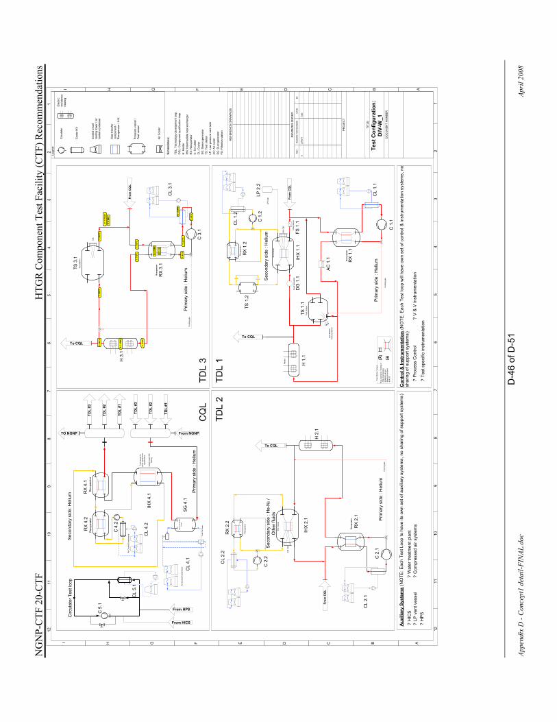
NG
NP-
CTF
20-
CTF
H
TGR
Com
pone
nt T
est F
acili
ty (C
TF) R
ecom
men
datio
ns
D-4
6 of
D-5
1
Appe
ndix
D -
Con
cept
1 de
tail-
FIN
AL.d
oc
Apri
l 200
8
IHX
Ves
sel
Test
Sta
tion:
Rec
uper
ator
Rec
uper
ator
Coo
ling
gas
IHX
C&
I
Dus
t Gen
erat
or
Test
Sta
tion
Inst
rum
enta
tion
Req
uire
men
ts: T
estin
g of
-Hot
circ
uit p
ipin
g-I
sola
tion
valv
es-M
ixin
g ch
ambe
rs-I
HX
LS
Test
Sta
tion
Vess
elP
rimar
y si
de :
Hel
ium
Sec
onda
ry s
ide
: Hel
ium
IHX
Ves
sel
Rec
uper
ator
Rec
uper
ator
Coo
ling
gas
IHX
C&I
Prim
ary
side
: H
eliu
m
Sec
onda
ry s
ide
: He-
N2
/ O
ther
flui
ds
Test
Sta
tion
Rec
uper
ator
Coo
ling
gas
C&I
Prim
ary
side
: H
eliu
m
TDL
#1
TDL
#2
TDL
#3
TDL
#1
TDL
#2
TDL
#3
Prim
ary
side
: H
eliu
m
From NGNP
To CQL
To CQL
From
CQ
L
From
CQ
L
From
CQ
L
Test
ves
sel f
or
larg
e co
mpo
nent
qu
alifi
catio
n
TO NGNP
Rec
uper
ator
Larg
e sc
ale
IHX
te
stin
g
To CQL
Stea
m G
ener
ator
Ves
sel
Feed
Pre
-hea
ter
Air
Coo
led
Con
dens
ers
Circ
ulat
or T
est l
oop
From HICS
From HPS
Filte
r sta
tion
H 1
.1H 3
.1
H 2
.1
Rec
uper
ator
Air C
oole
d C
onde
nser
s
C 1
.1
RX
1.1
TS 1
.1D
G 1
.1IH
X 1
.1FS
1.1
CL
1.1
TS 1
.2
Hea
ter
RX
1.2
C 1
.2
RX
3.1
C3.
1
CL
1.2
CL
3.1
TS3.
1
C2.
1
C2.
2
CL
2.1
IHX
2.1
CL
2.2
RX
2.1
RX
2.2
IHX
4.1R
X4.
1R
X4.
2
CL
4.2
SG
4.1
CL
4.1
C5.
1
CL
5.1
LP T
ank
LP2.
2
? H
ICS
? LP
ven
t ves
sel
? H
PS
? P
roce
ss C
ontro
l?
Wat
er tr
eatm
entp
lant
? C
ompr
esse
d ai
r sys
tem
s
? Te
st s
peci
fic in
stru
men
tatio
n
? V
& V
inst
rum
enta
tion
AC
1.1
Sec
onda
ry s
ide:
Hel
ium
Nom
encl
atur
e:
TDL:
Tec
hnol
ogy
deve
lopm
ent l
oop
CQ
L: C
ompo
nent
qua
lific
atio
n lo
opH
: Hea
ter
IHX
: Int
erm
edia
te h
eat e
xcha
nger
RX
: Rec
uper
ator
C: C
ircul
ator
CL:
Coo
ler
SG
: Ste
am g
ener
ator
TS: T
est s
tatio
nLP
: Low
pre
ssur
e ve
nt ta
nkA
C: A
ir co
oler
DG
: Dus
t gen
erat
orFS
: Filt
ratio
n st
atio
n
C 4
.2
12
34
56
78
910
1112
12
34
56
78
910
1112
ABCDEFGHI
ABCDEFGHI
NO
TES:
1.
REF
EREN
CE
DR
AWIN
GS
REV
ISIO
NS
ISSU
EDR
EV.
REA
SON
FO
R R
EVIS
ION
DAT
EBY
AD
RAF
TD
ate
PRO
JEC
T
[Nam
e]
[Dra
win
g Ti
tle]
[Dra
win
g N
umbe
r]
TITL
E
DO
CU
MEN
T N
UM
BER
Aux
iliar
y Sy
stem
s(N
OTE
: Eac
h Te
st L
oop
to h
ave
its o
wn
set o
f aux
iliar
y sy
stem
s, n
o sh
arin
g of
sup
port
syst
ems)
Con
trol
& In
stru
men
tatio
n(N
OTE
: Eac
h Te
st lo
op w
ill h
ave
own
set o
f con
trol &
inst
rum
enta
tion
syst
ems,
no
shar
ing
of s
uppo
rt sy
stem
s)
Lege
nd:
Hea
t tra
nsfe
r co
mpo
nent
/ R
ecup
erat
or /
IHX
Circ
ulat
or
Coo
ler H
X
Clo
sed
circ
uit
cool
ing
tow
er /
air
cool
ed c
onde
nser
Pre
ssur
e ve
ssel
/ Te
st v
esse
l
Air
Coo
ler
Elec
tric
resi
stan
ce
heat
ing
Test
Con
figur
atio
n:
DIV
-W_1
T: 9
50ºC
P: 9
MP
a
T: 9
50ºC
m: 1
.15k
g/s
T: 9
50ºC
Q: 1
.0 M
W
T: 7
76ºC
T: 9
50ºC
T: 8
3ºC
T: 2
57ºC
T: 7
76ºC Q
: 4.1
MW
Q: 1
.0 M
W
T: 8
0ºC
Eff
: 0.8

NG
NP-
CTF
20-
CTF
H
TGR
Com
pone
nt T
est F
acili
ty (C
TF) R
ecom
men
datio
ns
D-4
7 of
D-5
1
Appe
ndix
D -
Con
cept
1 de
tail-
FIN
AL.d
oc
Apri
l 200
8
IHX
Ves
sel
Test
Sta
tion:
Rec
uper
ator
Rec
uper
ator
Coo
ling
gas
IHX
C&
I
Dus
t Gen
erat
or
Test
Sta
tion
Inst
rum
enta
tion
Req
uire
men
ts: T
estin
g of
-Hot
circ
uit p
ipin
g-I
sola
tion
valv
es-M
ixin
g ch
ambe
rs-I
HX
LS
Test
Sta
tion
Ves
sel
Prim
ary
side
: H
eliu
m
Sec
onda
ry s
ide
: Hel
ium
IHX
Vess
el
Rec
uper
ator
Rec
uper
ator
Coo
ling
gas
IHX
C&I
Prim
ary
side
: H
eliu
m
Sec
onda
ry s
ide
: He-
N2
/ O
ther
flui
ds
Test
Sta
tion
Rec
uper
ator
Coo
ling
gas
C&I
Prim
ary
side
: H
eliu
m
TDL
#1
TDL
#2
TDL
#3
TDL
#1
TDL
#2
TDL
#3
Prim
ary
side
: H
eliu
m
From NGNP
To CQL
To CQL
From
CQ
L
From
CQ
L
From
CQ
L
Test
ves
sel f
or
larg
e co
mpo
nent
qu
alifi
catio
n
TO NGNP
Rec
uper
ator
Larg
e sc
ale
IHX
te
stin
g
To CQL
Stea
m G
ener
ator
Ves
sel
Feed
Pre
-hea
ter
Air C
oole
d C
onde
nser
s
Circ
ulat
or T
est l
oop
From HICS
From HPS
Filte
r sta
tion
H 1
.1H 3
.1
H 2
.1
Rec
uper
ator
Air C
oole
d C
onde
nser
s
C 1
.1
RX
1.1
TS 1
.1D
G 1
.1IH
X 1
.1FS
1.1
CL
1.1
TS 1
.2
Hea
ter
RX
1.2
C 1
.2
RX
3.1
C3.
1
CL
1.2
CL
3.1
TS3.
1
C2.
1
C2.
2
CL
2.1
IHX
2.1
CL
2.2
RX
2.1
RX
2.2
IHX
4.1R
X4.
1R
X4.
2
CL
4.2
SG
4.1
CL
4.1
C5.
1
CL
5.1
LP T
ank
LP2.
2
? H
ICS
? LP
ven
t ves
sel
? H
PS
? P
roce
ss C
ontro
l?
Wat
er tr
eatm
entp
lant
? C
ompr
esse
d ai
r sys
tem
s
? Te
st s
peci
fic in
stru
men
tatio
n
? V
& V
inst
rum
enta
tion
AC
1.1
Sec
onda
ry s
ide:
Hel
ium
Nom
encl
atur
e:
TDL:
Tec
hnol
ogy
deve
lopm
ent l
oop
CQ
L: C
ompo
nent
qua
lific
atio
n lo
opH
: Hea
ter
IHX
: Int
erm
edia
te h
eat e
xcha
nger
RX
: Rec
uper
ator
C: C
ircul
ator
CL:
Coo
ler
SG
: Ste
am g
ener
ator
TS: T
est s
tatio
nLP
: Low
pre
ssur
e ve
nt ta
nkA
C: A
ir co
oler
DG
: Dus
t gen
erat
orFS
: Filt
ratio
n st
atio
n
C 4
.2
12
34
56
78
910
1112
12
34
56
78
910
1112
ABCDEFGHI
ABCDEFGHI
NO
TES:
1.
REF
EREN
CE
DR
AWIN
GS
REV
ISIO
NS
ISSU
EDR
EV.
REA
SON
FO
R R
EVIS
ION
DAT
EBY
AD
RAF
TD
ate
PRO
JEC
T
[Nam
e]
[Dra
win
g Ti
tle]
[Dra
win
g N
umbe
r]
TITL
E
DO
CU
MEN
T N
UM
BER
Aux
iliar
y Sy
stem
s(N
OTE
: Eac
h Te
st L
oop
to h
ave
its o
wn
set o
f aux
iliar
y sy
stem
s, n
o sh
arin
g of
sup
port
syst
ems)
Con
trol
& In
stru
men
tatio
n(N
OTE
: Eac
h Te
st lo
op w
ill h
ave
own
set o
f con
trol &
inst
rum
enta
tion
syst
ems,
no
shar
ing
of s
uppo
rt sy
stem
s)
Lege
nd:
Hea
t tra
nsfe
r co
mpo
nent
/ R
ecup
erat
or /
IHX
Circ
ulat
or
Coo
ler H
X
Clo
sed
circ
uit
cool
ing
tow
er /
air
cool
ed c
onde
nser
Pre
ssur
e ve
ssel
/ Te
st v
esse
l
Air
Coo
ler
Elec
tric
resi
stan
ce
heat
ing
Test
Con
figur
atio
n:
DIV
-W_2
T: 9
50ºC
T: 9
50ºC
m: 5
.25
kg/s
P: 9
MP
a
T: 9
50ºC
T: 9
50ºC
T: 9
50ºC
T: 9
50ºC
T: 9
50ºC
T: 9
50ºC
T: 9
50ºC
m: 1
.75k
g/s
m: 1
.75k
g/s
m: 1
.75k
g/s
m: 1
.75k
g/s
m: 1
.75k
g/s
m: 1
.75k
g/s
T: 7
76ºC
Q: 1
.6 M
W
T:
950º
C
m: 1
.75k
g/s
T: 9
50ºC
T: 9
50ºC
T: 8
3ºC
T: 7
76ºC
T: 2
57ºC
Q: 6
.3 M
W
Eff:
0.8
T: 8
0ºC
Q: 1
.6 M
W
m: 1
.75k
g/s
T: 9
50ºC
T: 9
50ºC
T: 8
3ºC
T: 7
76ºC
T: 2
57ºC
Q: 6
.3 M
W
Eff
: 0.8
T: 8
0ºC
Q: 1
.6 M
W
T: 7
76ºC
Q: 1
.6 M
W
T: 9
50ºC
T: 7
76ºC
Q: 1
.6 M
W
T: 9
50ºC
T: 9
50ºC
T: 8
3ºC
T: 7
76ºC
T: 2
57ºC
Q: 6
.3 M
W
Eff:
0.8
T: 8
0ºC
Q: 1
.6 M
W
m: 1
.75k
g/s
T: 9
50ºC

NG
NP-
CTF
20-
CTF
H
TGR
Com
pone
nt T
est F
acili
ty (C
TF) R
ecom
men
datio
ns
D-4
8 of
D-5
1
Appe
ndix
D -
Con
cept
1 de
tail-
FIN
AL.d
oc
Apri
l 200
8
IHX
Ves
sel
Test
Sta
tion:
Rec
uper
ator
Rec
uper
ator
Coo
ling
gas
IHX
C&
I
Dus
t Gen
erat
or
Test
Sta
tion
Inst
rum
enta
tion
Req
uire
men
ts: T
estin
g of
-Hot
circ
uit p
ipin
g-I
sola
tion
valv
es-M
ixin
g ch
ambe
rs-I
HX
LS
Test
Sta
tion
Ves
sel
Prim
ary
side
: H
eliu
m
Sec
onda
ry s
ide
: Hel
ium
IHX
Ves
sel
Rec
uper
ator
Rec
uper
ator
Coo
ling
gas
IHX
C&I
Prim
ary
side
: H
eliu
m
Sec
onda
ry s
ide
: He-
N2
/ O
ther
flui
ds
Test
Sta
tion
Rec
uper
ator
Coo
ling
gas
C&I
Prim
ary
side
: H
eliu
m
TDL
#1
TDL
#2
TDL
#3
TDL
#1
TDL
#2
TDL
#3
Prim
ary
side
: H
eliu
m
From NGNP
To CQL
To CQL
From
CQ
L
From
CQ
L
From
CQ
L
Test
ves
sel f
or
larg
e co
mpo
nent
qu
alifi
catio
n
TO NGNP
Rec
uper
ator
Larg
e sc
ale
IHX
te
stin
g
To CQL
Stea
m G
ener
ator
Ves
sel
Feed
Pre
-hea
ter
Air C
oole
d C
onde
nser
s
Circ
ulat
or T
est l
oop
From HICS
From HPS
Filte
r sta
tion
H 1
.1H 3
.1
H 2
.1
Rec
uper
ator
Air
Coo
led
Con
dens
ers
C 1
.1
RX
1.1
TS 1
.1D
G 1
.1IH
X 1
.1FS
1.1
CL
1.1
TS 1
.2
Hea
ter
RX
1.2
C 1
.2
RX
3.1
C3.
1
CL
1.2
CL
3.1
TS3.
1
C2.
1
C2.
2
CL
2.1
IHX
2.1
CL
2.2
RX
2.1
RX
2.2
IHX
4.1R
X4.
1R
X4.
2
CL
4.2
SG
4.1
CL
4.1
C5.
1
CL
5.1
LP T
ank
LP2.
2
? H
ICS
? LP
ven
t ves
sel
? H
PS
? P
roce
ss C
ontro
l?
Wat
er tr
eatm
entp
lant
? C
ompr
esse
d ai
r sys
tem
s
? Te
st s
peci
fic in
stru
men
tatio
n
? V
& V
inst
rum
enta
tion
AC
1.1
Sec
onda
ry s
ide:
Hel
ium
Nom
encl
atur
e:
TDL:
Tec
hnol
ogy
deve
lopm
ent l
oop
CQ
L: C
ompo
nent
qua
lific
atio
n lo
opH
: Hea
ter
IHX
: Int
erm
edia
te h
eat e
xcha
nger
RX
: Rec
uper
ator
C: C
ircul
ator
CL:
Coo
ler
SG
: Ste
am g
ener
ator
TS: T
est s
tatio
nLP
: Low
pre
ssur
e ve
nt ta
nkA
C: A
ir co
oler
DG
: Dus
t gen
erat
orFS
: Filt
ratio
n st
atio
n
C 4
.2
12
34
56
78
910
1112
12
34
56
78
910
1112
ABCDEFGHI
ABCDEFGHI
NO
TES:
1.
REF
EREN
CE
DR
AWIN
GS
REV
ISIO
NS
ISSU
EDR
EV.
REA
SON
FO
R R
EVIS
ION
DAT
EBY
AD
RAF
TD
ate
PRO
JEC
T
[Nam
e]
[Dra
win
g Ti
tle]
[Dra
win
g N
umbe
r]
TITL
E
DO
CU
MEN
T N
UM
BER
Aux
iliar
y Sy
stem
s(N
OTE
: Eac
h Te
st L
oop
to h
ave
its o
wn
set o
f aux
iliar
y sy
stem
s, n
o sh
arin
g of
sup
port
syst
ems)
Con
trol
& In
stru
men
tatio
n(N
OTE
: Eac
h Te
st lo
op w
ill h
ave
own
set o
f con
trol &
inst
rum
enta
tion
syst
ems,
no
shar
ing
of s
uppo
rt sy
stem
s)
Lege
nd:
Hea
t tra
nsfe
r co
mpo
nent
/ R
ecup
erat
or /
IHX
Circ
ulat
or
Coo
ler H
X
Clo
sed
circ
uit
cool
ing
tow
er /
air
cool
ed c
onde
nser
Pre
ssur
e ve
ssel
/ Te
st v
esse
l
Air
Coo
ler
Ele
ctric
re
sist
ance
he
atin
g
Test
Con
figur
atio
n:
SG-W
_1
T: 9
00 ºC
T: 2
72 º
C
Q: 1
1.2
MW
m: 3
.45
kg/s
T: 9
00 ºC
T: 9
00 ºC
T: 9
00 ºC
m: 1
.15
kg/s
T: 2
72 ºC
T: 2
72 ºC
T: 2
72 ºC
m: 1
.15
kg/s
m: 1
.15
kg/s
m: 1
.15
kg/s
m: 1
.15
kg/s
m: 1
.15
kg/s
T: 2
19ºC
T: 5
39 ºC
m: 3
.0 k
g/s
T: 5
4ºC
P: 1
5 kP
a
P: 1
8 M
PaT: 5
4ºC
Wat
er V
apor
P: 9
MP
a
T: 9
00 ºC
T:23
4 ºC
Q: 4
.0 M
W
m: 1
.15
kg/s
T:27
2 ºC
T:27
2 ºC
T: ~
83º
C
T: 1
21 ºC
T:23
4 ºC
Q: 0
.9 M
W
Eff
: 0.8
T: 8
0 ºC
Q: 0
.2 M
W
m: 1
.15
kg/s
T:27
2 ºC
T:27
2 ºC
T: ~
83º
C
T: 1
21 ºC
T:23
4 ºC Q: 0
.9 M
W
Eff
: 0.8
T: 8
0 ºC
Q: 0
.2 M
W
T: 9
00 º
C
T:23
4 ºC
Q: 4
.0 M
W
m: 1
.15
kg/s
T:27
2 ºC
T:27
2 ºC
T: ~
83º
CT:
121
ºC
T:23
4 ºC Q
: 0.9
MW
Eff:
0.8
T: 8
0 ºC
Q: 0
.2 M
W
T: 9
00 º
C
T:23
4 ºCQ
: 4.0
MW

NG
NP-
CTF
20-
CTF
H
TGR
Com
pone
nt T
est F
acili
ty (C
TF) R
ecom
men
datio
ns
D-4
9 of
D-5
1
Appe
ndix
D -
Con
cept
1 de
tail-
FIN
AL.d
oc
Apri
l 200
8
IHX
Ves
sel
Test
Sta
tion:
Rec
uper
ator
Rec
uper
ator
Coo
ling
gas
IHX
C&
I
Dus
t Gen
erat
or
Test
Sta
tion
Inst
rum
enta
tion
Req
uire
men
ts: T
estin
g of
-Hot
circ
uit p
ipin
g-I
sola
tion
valv
es-M
ixin
g ch
ambe
rs-I
HX
LS
Test
Sta
tion
Ves
sel
Prim
ary
side
: H
eliu
m
Sec
onda
ry s
ide
: Hel
ium
IHX
Ves
sel
Rec
uper
ator
Rec
uper
ator
Coo
ling
gas
IHX
C&
I
Prim
ary
side
: H
eliu
m
Sec
onda
ry s
ide
: He-
N2
/ O
ther
flui
ds
Test
Sta
tion
Rec
uper
ator
Coo
ling
gas
C&I
Prim
ary
side
: H
eliu
m
TDL
#1
TDL
#2
TDL
#3
TDL
#1
TDL
#2
TDL
#3
Prim
ary
side
: H
eliu
m
From NGNP
To CQL
To CQL
From
CQ
L
From
CQ
L
From
CQ
L
Test
ves
sel f
or
larg
e co
mpo
nent
qu
alifi
catio
n
TO NGNP
Rec
uper
ator
Larg
e sc
ale
IHX
te
stin
g
To CQL
Stea
m G
ener
ator
Ves
sel
Feed
Pre
-hea
ter
Air
Coo
led
Con
dens
ers
Circ
ulat
or T
est l
oop
From HICS
From HPS
Filte
r sta
tion
H 1
.1H 3
.1
H 2
.1
Rec
uper
ator
Air C
oole
d C
onde
nser
s
C 1
.1
RX
1.1
TS 1
.1D
G 1
.1IH
X 1
.1FS
1.1
CL
1.1
TS 1
.2
Hea
ter
RX
1.2
C 1
.2
RX
3.1
C3.
1
CL
1.2
CL
3.1
TS3.
1
C2.
1
C2.
2
CL
2.1
IHX
2.1
CL
2.2
RX
2.1
RX
2.2
IHX
4.1R
X4.
1R
X4.
2
CL
4.2
SG
4.1
CL
4.1
C5.
1
CL
5.1
LP T
ank
LP2.
2
? H
ICS
? LP
ven
t ves
sel
? H
PS
? P
roce
ss C
ontro
l?
Wat
er tr
eatm
entp
lant
? C
ompr
esse
d ai
r sys
tem
s
? Te
st s
peci
fic in
stru
men
tatio
n
? V
& V
inst
rum
enta
tion
AC
1.1
Sec
onda
ry s
ide:
Hel
ium
Nom
encl
atur
e:
TDL:
Tec
hnol
ogy
deve
lopm
ent l
oop
CQ
L: C
ompo
nent
qua
lific
atio
n lo
opH
: Hea
ter
IHX
: Int
erm
edia
te h
eat e
xcha
nger
RX
: Rec
uper
ator
C: C
ircul
ator
CL:
Coo
ler
SG
: Ste
am g
ener
ator
TS: T
est s
tatio
nLP
: Low
pre
ssur
e ve
nt ta
nkA
C: A
ir co
oler
DG
: Dus
t gen
erat
orFS
: Filt
ratio
n st
atio
n
C 4
.2
12
34
56
78
910
1112
12
34
56
78
910
1112
ABCDEFGHI
ABCDEFGHI
NO
TES:
1.
REF
EREN
CE
DR
AWIN
GS
REV
ISIO
NS
ISSU
EDR
EV.
REA
SON
FO
R R
EVIS
ION
DAT
EBY
AD
RAF
TD
ate
PRO
JEC
T
[Nam
e]
[Dra
win
g Ti
tle]
[Dra
win
g N
umbe
r]
TITL
E
DO
CU
MEN
T N
UM
BER
Aux
iliar
y Sy
stem
s(N
OTE
: Eac
h Te
st L
oop
to h
ave
its o
wn
set o
f aux
iliar
y sy
stem
s, n
o sh
arin
g of
sup
port
syst
ems)
Con
trol
& In
stru
men
tatio
n(N
OTE
: Eac
h Te
st lo
op w
ill h
ave
own
set o
f con
trol &
inst
rum
enta
tion
syst
ems,
no
shar
ing
of s
uppo
rt sy
stem
s)
Lege
nd:
Hea
t tra
nsfe
r co
mpo
nent
/ R
ecup
erat
or /
IHX
Circ
ulat
or
Coo
ler H
X
Clo
sed
circ
uit
cool
ing
tow
er /
air
cool
ed c
onde
nser
Pre
ssur
e ve
ssel
/ Te
st v
esse
l
Air
Coo
ler
Elec
tric
resi
stan
ce
heat
ing
Test
Con
figur
atio
n:
CIR
-W
m: 1
59 k
g/s
T: 3
37ºC
T: 3
50ºC
Q: 1
0.8
MW
tP:
11.
4 M
We
T: 3
37ºC
Q: 1
0.8
MW
t
T: 2
72ºC
T: 2
87ºC
Q: 1
2.4
MW
tP:
13.
0 M
We
T: 2
72ºC
Q: 1
2.4
MW
t
P: 9
MP
a

NG
NP-
CTF
20-
CTF
H
TGR
Com
pone
nt T
est F
acili
ty (C
TF) R
ecom
men
datio
ns
D-5
0 of
D-5
1
Appe
ndix
D -
Con
cept
1 de
tail-
FIN
AL.d
oc
Apri
l 200
8
IHX
Ves
sel
Test
Sta
tion:
Rec
uper
ator
Rec
uper
ator
Coo
ling
gas
IHX
C&
I
Dus
t Gen
erat
or
Test
Sta
tion
Inst
rum
enta
tion
Req
uire
men
ts: T
estin
g of
-Hot
circ
uit p
ipin
g-I
sola
tion
valv
es-M
ixin
g ch
ambe
rs-I
HX
LS
Test
Sta
tion
Vess
elP
rimar
y si
de :
Hel
ium
Sec
onda
ry s
ide
: Hel
ium
IHX
Ves
sel
Rec
uper
ator
Rec
uper
ator
Coo
ling
gas
IHX
C&I
Prim
ary
side
: H
eliu
m
Sec
onda
ry s
ide
: He-
N2
/ O
ther
flui
ds
Test
Sta
tion
Rec
uper
ator
Coo
ling
gas
C&I
Prim
ary
side
: H
eliu
m
TDL
#1
TDL
#2
TDL
#3
TDL
#1
TDL
#2
TDL
#3
Prim
ary
side
: H
eliu
m
From NGNP
To CQL
To CQL
From
CQ
L
From
CQ
L
From
CQ
L
Test
ves
sel f
or
larg
e co
mpo
nent
qu
alifi
catio
n
TO NGNP
Rec
uper
ator
Larg
e sc
ale
IHX
te
stin
g
To CQL
Stea
m G
ener
ator
Ves
sel
Feed
Pre
-hea
ter
Air
Coo
led
Con
dens
ers
Circ
ulat
or T
est l
oop
From HICS
From HPS
Filte
r sta
tion
H 1
.1H 3
.1
H 2
.1
Rec
uper
ator
Air C
oole
d C
onde
nser
s
C 1
.1
RX
1.1
TS 1
.1D
G 1
.1IH
X 1
.1FS
1.1
CL
1.1
TS 1
.2
Hea
ter
RX
1.2
C 1
.2
RX
3.1
C3.
1
CL
1.2
CL
3.1
TS3.
1
C2.
1
C2.
2
CL
2.1
IHX
2.1
CL
2.2
RX
2.1
RX
2.2
IHX
4.1R
X4.
1R
X4.
2
CL
4.2
SG
4.1
CL
4.1
C5.
1
CL
5.1
LP T
ank
LP2.
2
? H
ICS
? LP
ven
t ves
sel
? H
PS
? P
roce
ss C
ontro
l?
Wat
er tr
eatm
entp
lant
? C
ompr
esse
d ai
r sys
tem
s
? Te
st s
peci
fic in
stru
men
tatio
n
? V
& V
inst
rum
enta
tion
AC
1.1
Sec
onda
ry s
ide:
Hel
ium
Nom
encl
atur
e:
TDL:
Tec
hnol
ogy
deve
lopm
ent l
oop
CQ
L: C
ompo
nent
qua
lific
atio
n lo
opH
: Hea
ter
IHX
: Int
erm
edia
te h
eat e
xcha
nger
RX
: Rec
uper
ator
C: C
ircul
ator
CL:
Coo
ler
SG
: Ste
am g
ener
ator
TS: T
est s
tatio
nLP
: Low
pre
ssur
e ve
nt ta
nkA
C: A
ir co
oler
DG
: Dus
t gen
erat
orFS
: Filt
ratio
n st
atio
n
C 4
.2
12
34
56
78
910
1112
12
34
56
78
910
1112
ABCDEFGHI
ABCDEFGHI
NO
TES:
1.
REF
EREN
CE
DR
AWIN
GS
REV
ISIO
NS
ISSU
EDR
EV.
REA
SON
FO
R R
EVIS
ION
DAT
EBY
AD
RAF
TD
ate
PRO
JEC
T
[Nam
e]
[Dra
win
g Ti
tle]
[Dra
win
g N
umbe
r]
TITL
E
DO
CU
MEN
T N
UM
BER
Aux
iliar
y Sy
stem
s(N
OTE
: Eac
h Te
st L
oop
to h
ave
its o
wn
set o
f aux
iliar
y sy
stem
s, n
o sh
arin
g of
sup
port
syst
ems)
Con
trol
& In
stru
men
tatio
n(N
OTE
: Eac
h Te
st lo
op w
ill h
ave
own
set o
f con
trol &
inst
rum
enta
tion
syst
ems,
no
shar
ing
of s
uppo
rt sy
stem
s)
Lege
nd:
Hea
t tra
nsfe
r co
mpo
nent
/ R
ecup
erat
or /
IHX
Circ
ulat
or
Coo
ler H
X
Clo
sed
circ
uit
cool
ing
tow
er /
air
cool
ed c
onde
nser
Pre
ssur
e ve
ssel
/ Te
st v
esse
l
Air
Coo
ler
Elec
tric
resi
stan
ce
heat
ing
Test
Con
figur
atio
n:
CIR
-G
m: 3
4.7
kg/s
T: 5
90ºC
Q: 1
.5 M
Wt
T: 5
90ºC
Q: 1
.5 M
Wt
T: 5
98ºC
T: 5
98ºC
P: 7
MPa

NG
NP-
CTF
20-
CTF
H
TGR
Com
pone
nt T
est F
acili
ty (C
TF) R
ecom
men
datio
ns
D-5
1 of
D-5
1
Appe
ndix
D -
Con
cept
1 de
tail-
FIN
AL.d
oc
Apri
l 200
8
IHX
Ves
sel
Test
Sta
tion:
Rec
uper
ator
Rec
uper
ator
Coo
ling
gas
IHX
C&
I
Dus
t Gen
erat
or
Test
Sta
tion
Inst
rum
enta
tion
Req
uire
men
ts: T
estin
g of
-Hot
circ
uit p
ipin
g-I
sola
tion
valv
es-M
ixin
g ch
ambe
rs-I
HX
LS
Test
Sta
tion
Vess
elP
rimar
y si
de :
Hel
ium
Sec
onda
ry s
ide
: Hel
ium
IHX
Ves
sel
Rec
uper
ator
Rec
uper
ator
Coo
ling
gas
IHX
C&
I
Prim
ary
side
: H
eliu
m
Sec
onda
ry s
ide
: He-
N2
/ O
ther
flui
ds
Test
Sta
tion
Rec
uper
ator
Coo
ling
gas
C&I
Prim
ary
side
: H
eliu
m
TDL
#1
TDL
#2
TDL
#3
TDL
#1
TDL
#2
TDL
#3
Prim
ary
side
: H
eliu
m
From NGNP
To CQL
To CQL
From
CQ
L
From
CQ
L
From
CQ
L
Test
ves
sel f
or
larg
e co
mpo
nent
qu
alifi
catio
n
TO NGNP
Rec
uper
ator
Larg
e sc
ale
IHX
te
stin
g
To CQL
Stea
m G
ener
ator
Ves
sel
Feed
Pre
-hea
ter
Air C
oole
d C
onde
nser
s
Circ
ulat
or T
est l
oop
From HICS
From HPS
Filte
r sta
tion
H 1
.1H 3
.1
H 2
.1
Rec
uper
ator
Air C
oole
d C
onde
nser
s
C 1
.1
RX
1.1
TS 1
.1D
G 1
.1IH
X 1
.1FS
1.1
CL
1.1
TS 1
.2
Hea
ter
RX
1.2
C 1
.2
RX
3.1
C3.
1
CL
1.2
CL
3.1
TS3.
1
C2.
1
C2.
2
CL
2.1
IHX
2.1
CL
2.2
RX
2.1
RX
2.2
IHX
4.1R
X4.
1R
X4.
2
CL
4.2
SG
4.1
CL
4.1
C5.
1
CL
5.1
LP T
ank
LP2.
2
? H
ICS
? LP
ven
t ves
sel
? H
PS
? P
roce
ss C
ontro
l?
Wat
er tr
eatm
entp
lant
? C
ompr
esse
d ai
r sys
tem
s
? Te
st s
peci
fic in
stru
men
tatio
n
? V
& V
inst
rum
enta
tion
AC
1.1
Sec
onda
ry s
ide:
Hel
ium
Nom
encl
atur
e:
TDL:
Tec
hnol
ogy
deve
lopm
ent l
oop
CQ
L: C
ompo
nent
qua
lific
atio
n lo
opH
: Hea
ter
IHX
: Int
erm
edia
te h
eat e
xcha
nger
RX
: Rec
uper
ator
C: C
ircul
ator
CL:
Coo
ler
SG
: Ste
am g
ener
ator
TS: T
est s
tatio
nLP
: Low
pre
ssur
e ve
nt ta
nkA
C: A
ir co
oler
DG
: Dus
t gen
erat
orFS
: Filt
ratio
n st
atio
n
C 4
.2
12
34
56
78
910
1112
12
34
56
78
910
1112
ABCDEFGHI
ABCDEFGHI
NO
TES:
1.
REF
EREN
CE
DR
AWIN
GS
REV
ISIO
NS
ISSU
EDR
EV.
REA
SON
FO
R R
EVIS
ION
DAT
EBY
AD
RAF
TD
ate
PRO
JEC
T
[Nam
e]
[Dra
win
g Ti
tle]
[Dra
win
g N
umbe
r]
TITL
E
DO
CU
MEN
T N
UM
BER
Aux
iliar
y Sy
stem
s(N
OTE
: Eac
h Te
st L
oop
to h
ave
its o
wn
set o
f aux
iliar
y sy
stem
s, n
o sh
arin
g of
sup
port
syst
ems)
Con
trol
& In
stru
men
tatio
n(N
OTE
: Eac
h Te
st lo
op w
ill h
ave
own
set o
f con
trol &
inst
rum
enta
tion
syst
ems,
no
shar
ing
of s
uppo
rt sy
stem
s)
Lege
nd:
Hea
t tra
nsfe
r co
mpo
nent
/ R
ecup
erat
or /
IHX
Circ
ulat
or
Coo
ler H
X
Clo
sed
circ
uit
cool
ing
tow
er /
air
cool
ed c
onde
nser
Pre
ssur
e ve
ssel
/ Te
st v
esse
l
Air
Coo
ler
Elec
tric
resi
stan
ce
heat
ing
Test
Con
figur
atio
n:
CIR
-A
m: 1
36 k
g/s
Q: 5
MW
t
Q: 5
MW
t
T: 4
96.5
ºC
P: 5
MPa
T: 4
89.5
ºC
T: 4
89.5
ºC
T: 4
96.5
ºC

NGNP-CTF 20-CTF HTGR Component Test Facility (CTF) Recommendations
E-1 of E-14 Appendix E – Concept 2 Detail-FINAL.doc April 2008
APPENDIX E CONCEPT 2 DETAILS
1.1 TEST CONFIGURATIONS
In order to provide a recommendation with regards to facility envelope sizes, a number of different test configurations were imposed on Concept 2. These test configurations are summed up in Table 1, and were evaluated by means of energy balances to determine component sizing. A complete summary of these energy balances, together with general considerations per test configuration can be found in at the end of this appendix. The “TEST#” column in Table 1 corresponds with the “DOCUMENT NUMBER” on the energy balance sheet.
Table 1: Summary of Test Configurations in Concept 2 as Dictated by the DDNs
Test # Main Test Configuration Sub Test LoopIHX- 1 IHX Performance verification
tests: WEC Core A & B Steady state Primary /
Secondary DIV- 1 High temperature ducts &
insulation performance verification test)
Steady state Secondary
SG-1 Steam generator performance verification test: WEC
Steady state Steam generator testing loop
CIR-W Circulator performance: WEC Steady state Circulator loop
The enveloping values for each loop, from these test configurations and the energy balances, will be presented in the following section.
1.1.1 Concept 2 – Primary Side
The primary loop of Concept 2 is very similar to the primary side of the TDLs of Concept 1. Helium is circulated at a maximum rate of 25 kg/s with two 650 kW circulators (C1.1 & 1.2) while the other main components include large scale electrical heaters (H 1.1), double vessel test stations (TS 1.1) as well as the IHX test station vessels (IHX 1.1 & 1.2). Figure 1 illustrates the primary loop, with the maximum component values following thereafter.

NGNP-CTF 20-CTF HTGR Component Test Facility (CTF) Recommendations
E-2 of E-14 Appendix E – Concept 2 Detail-FINAL.doc April 2008
Figure 1: High Level Process Flow Diagram of Concept 2 Primary Side
Table 2: Enveloping Values of the Primary Side of Concept 2
Concept 2 – Primary side
No. Components Power [MW]
Mass flow rate [kg/s] -
MAXT_in[°C]
T_out[°C] Pressure Fluid
C 1.1 & 1.2
Circulator (�P: 500 kPa @ 9 MPa) 1.9 25 250[max] -
RX 1.1 Recuperator (Hot side) 25 925 [max]
394 [max]
RX 1.1 Recuperator (Cold side)
68 [max] 25 ~ 263
[max] 793
[max]
H 1.1 Heater 23 25 793 [max]
950 [max]
TS 1.1 Vessel - Test Station N/A 25 950 [min]
950 [max]
IHX 1.1 Heat exchanger Vessel (primary) N/A 25 950
[max] 950
[max]
CL 1.1 Cooler 19 25 396 [max]
250 [nom]
PD 1.1 Pipe & Ducting N/A 25 950 [max]
9 MPa (Calculations based only on 9 MPa)
Pure Helium
1.1.2 Concept 2 – Secondary Side The secondary side of Concept 2 is again similar to that of the TDL’s of Concept 1 and is will be used during IHX testing. This loop also has two test vessels, apart from the IHX test vessels and could be used for concurrent testing of non heat transfer components. A simplified PFD of the secondary loop is illustrated in Figure 2, while the component values follow thereafter.
IHX A Test Core
IHX Vessel
IHX B Test Core
IHX VesselTest Station:
Test Station:
CoolerCL 1.1
Circulator
C1.1 & C1.2
Heater
H1.1RecuperatorRX1.1 IHX 1.1 IHX 1.2TS1.1
TS1.2

NGNP-CTF 20-CTF HTGR Component Test Facility (CTF) Recommendations
E-3 of E-14 Appendix E – Concept 2 Detail-FINAL.doc April 2008
IHX A Test Core
IHX Vessel
IHX Spool piece
IHX A Test Core
IHX Vessel
IHX Spool piece
Test Station:
Test Station:
Test Station:
Test Station:
Secondary Loop
Circulator
C2.1 & C2.2
Heater
H1.1
Recuperator
RX1.1IHX 1.1
IHX 1.2TS1.1
TS1.2
H2.1
Heater
TS2.1
TS2.2
CoolerCL 2.1
Figure 2: High Level Process Flow Diagram of Concept 2 Secondary Side
Table 3: Enveloping Values of the Secondary Side of Concept 2
Concept 2 – Secondary side
No. Components Power [MW]
Mass flow rate [kg/s] -
MAXT_in[°C]
T_out[°C] Pressure Fluid
C 2.1 & 2.2
Circulator (�P: 500 kPa @ 9 MPa) 1.9 25 250[max] -
H 2.1 Heater 3.1 25 263 [max]
287 [max]
TS 2.1 Vessel - Test Station N/A 25 950 [min]
950 [max]
CL 2.1 Cooler 18.2 25 390 [max]
250 [nom]
9 MPa (Calculations based only on 9 MPa)
Pure Helium
1.1.3 Concept 2 – Steam Generator Loop The steam generator loop is a separate loop which extends the primary loop for specific steam generator testing. This separate loop will provide representative steam producing capabilities on the water side of the steam generator with the required condensing capabilities.

NGNP-CTF 20-CTF HTGR Component Test Facility (CTF) Recommendations
E-4 of E-14 Appendix E – Concept 2 Detail-FINAL.doc April 2008
IHX Test Core
IHX Vessel
IHX Spool piece
IHX Test Core
IHX Vessel
IHX Spool piece
Feed Pre-heater
Air Cooled Condensers
Steam generator
Test Stations
Heater
Recuperator
Circulators
Cooler
Cooler
Figure 3: High Level Process Flow Diagram of Concept 2 in the Steam Generator Configuration
Table 4: Enveloping Values Maximum Steam Generator Testing Capability
Concept 2 – Secondary side
No. Components Power [MW]
Mass flow rate [kg/s] -
MAXT_in[°C]
T_out[°C] Pressure Fluid
SG Unit under test
23.2 7.15 900 [max]
272 [max]
9 MPa (Calculations based only on 9 MPa)
Pure Helium
CL 3.1 Cooler 17 6.23 (Water)
54 (vapor) [max]
54 (liquid) [nom]
18 MPa Water
Details regarding the specific components that are proposed for each of these loops will be provided in the component descriptions.

NGNP-CTF 20-CTF HTGR Component Test Facility (CTF) Recommendations
E-5 of E-14 Appendix E – Concept 2 Detail-FINAL.doc April 2008
1.1.4 Full Scale Circulator Loop A circulator testing loop is purposed again to address full scale testing requirements of different circulator designs as in Concept 1. This separate loop is mainly proposed as part of the philosophy of not having two or more components under test in a single test configuration. A typical arrangement is shown in Figure 4, with a summary of the main components in Table 5.
Full scale Circulator test loop
From HICS
From HPS
C 4.1
CL 4.1
Figure 4: High Level Process Flow Diagram of the Full Scale Circulator Test Loop
Table 5: Enveloping Values of the Full Scale Circulator Test Loop
Circulator test loop
No. Components Power [MW]
Mass flow rate [kg/s] -
MAXT_in[°C]
T_out[°C] Pressure Fluid
C 4.1 Circulator: Unit under test
12.4 MWt [max] 159.6 [max] 337
[max] -
CL 5.1 Cooler 12.4 [max] 159.6 [max] 350 [max]
337 [min]
PD 5.1 Pipe & Ducting N/A 159.6 [max] 350 [max]
9 MPa Helium.

NGNP-CTF 20-CTF HTGR Component Test Facility (CTF) Recommendations
E-6 of E-14 Appendix E – Concept 2 Detail-FINAL.doc April 2008
1.2 COMPONENT DESCRIPTIONS
This section provides a general description and recommendations for future work on the different components and sub systems of Concept 2.
1.2.1 Circulators
The Circulators used for Concept 2 employ the same philosophy as for the TDLs. However, the circulators for Concept 2 require research and development during design and are therefore not COTS items. For the same reason, two full flow circulators are employed, with one used for redundancy. A single stage high-speed circulator is the preferred option with an oil bearing and seal combination as in the case of the TDL circulators. The Circulator must circulate Helium at a process flow rate of 25kg/s. Allowance should be made for a bypass of at least 15% of the process flow to account for Surge Control. It is estimated that a pressure drop of 450 kPa is required, which gives a pressure ratio of 1.05 at an inlet total pressure of 9.0 MPa. It is therefore critical that the piping and associated components have a low pressure drop. If a higher pressure ratio is required, a multi-stage radial or axial circulator will be required. The estimated driver power is 1.6 MW.
The proposed circulator layout is typically a Howden submerged motor circulator with AMBs that is modified to accommodate oil bearing or dry gas seals. The approach is to utilize a highly reliable product for the test loop, but provide flexibility in introducing new developed product such as submerged motor circulators with AMBs.
1.2.2 Heater Unit The Heater Unit for Concept 2 employs a similar philosophy as for the TDLs. The heater will however, be divided into two units which use various smaller heaters placed in series in the two pressure vessels. The heaters are also electrically powered with thyristor control. The pressure vessel is thermally insulated from the high temperature gas, as well as protected against heating element radiation. The heater unit is installed in a vertical position with the gas flowing in an upwards direction. The heater has a typical inlet temperature of 700°C and an outlet temperature of 950°C. Each heater has a flow rate of 12.5 kg/s.
Each heater vessel has an estimated size of Ø of 2.5m, a height of 8m and weighs approximately 120 metric tons.
1.2.3 Pressure Boundary
Hot Pipes (THelium>550°C)
The hot-pipes will be of a similar design and construction as those developed in Germany for the high temperature gas cooled reactor program. It also follows the PBMR approach.
The construction is made up of an inner gas guiding tube, thermally well insulated, with a gap between the actual pressure pipe and this insulated inner pipe (similar to the TDL design). This

NGNP-CTF 20-CTF HTGR Component Test Facility (CTF) Recommendations
E-7 of E-14 Appendix E – Concept 2 Detail-FINAL.doc April 2008
gap is thermally conditioned by forced convection of cooling gas provided by an independent circulator system.
A maximum flow tube diameter of 0.35 m is calculated at a nominal flow rate of 25 kg/s and a flow velocity of 80 m/s at 950°C, 9 MPa. The pressure boundary dimensions are to be determined once a detail calculation has been done regarding the insulation material, but is estimated at approximately 1.0 – 1.2 m with active cooling. The pressure boundary section should make provision for instrumentation connection points which can be used to monitor the pressure and temperature levels in the hot pipe. The hot pipes should be designed to be pressure balanced across the flow tube and the possibility of isolating these two sides from each other should be investigated and could assist in the purification processes. A typical section length of 5m is foreseen. As a result of the high cost of this pipe, the physical layout should be done sensitively to keep the total length of this item to a minimum. The governing philosophy for the hot pipes is to make them as short as possible, have no valves located in them, have no compensators in them but rather compensate in the cold pipes and have minimal bends except when the bends are actually used for compensating purposes.
Cold Pipes (THelium<350°C)
It is recommended that all the cold pipes are manufactured from carbon steel, such as ASMEA106 Gr B.
The use of carbon steel would reduce the total cost of the facility but the risk of corrosion of the piping in periods when the facility is open for maintenance, test setups and/or repair is increased. Tradeoff studies need to be performed in the Intermediate design phase to weigh financial and long term life contamination issues due to rust, etc. A maximum pipe flow diameter of 0.25 m is calculated at a nominal flow rate of 25 kg/s and a flow velocity of 80 m/s at 350°C, 9 MPa. The effect of erosion of the inner surface of the pipe should be investigated at these very high flow velocities.
1.2.4 Valves The layout of the process loop was carefully done to eliminate the need for valves. Valves operating in a high temperature helium environment are not readily available commercially and must be developed for the specific application. Some tests that are done in parallel might require the use of valves for helium flow control. Bellow-sealed valves (bellow on the stem) are the best option for helium applications. Rotational valve stems require a different sealing concept. Multi-stage wet oil/grease seals will successfully seal off the high pressure helium against leaks to atmosphere (10-5mbar.l/ sec per stem can be achieved). The actuation can be by pneumatic or electric actuators.
1.2.5 Test Vessels The test of specific full size components or representative size components for the NGNP required custom “designed-for” test vessels. The test loop provides space and the necessary interfaces for a few high-pressure test setups. The design of the test vessels should allow for Human Factors (HF), seeing that these vessels will be used extensively for different UUT setups that require adequate space for maneuverability and internal piping. These vessels must be

NGNP-CTF 20-CTF HTGR Component Test Facility (CTF) Recommendations
E-8 of E-14 Appendix E – Concept 2 Detail-FINAL.doc April 2008
thermally conditioned by a thermal conditioning system. The temperature of the vessels should preferably be low enough to eliminate any thermal insulation.
Provision is made for three test setups. Two dedicated test vessels are provided, one being vertically oriented and one horizontally oriented. The third setup allows the vendors to connect directly to the process loop via a “test spool piece”. The test spool piece is a UUT and can typically be a component such as a hot pipe design, etc.
Even though one can only use a single test vessel at a time, vendors will be able to do three simultaneous setups during plant outage. The selection between different test setups can then be done by minor configuration changes without necessarily shutting down the plant.
The envisaged size of the horizontal test vessel has an inner diameter of approximately of 2.0m and a length of 15m. The vertical test vessel’s inner diameter is approximately 2.0m with a height of 5m. A distance of 15m is available between the process connections to connect UUTs via a “test spool piece”.
1.2.6 Heat Transfer Components
Recuperator
The recuperator unit in the loop is used to recover the energy input of the Heater units after the UUTs. To ensure that the process loops’ design integrity is one level higher than the units under test, requires that conventional type recuperators be used.
In the event where tests are conducted and little or no heat is rejected by the test components such as valve tests and hot ducts and insulation tests, the inlet temperature of the recuperator can reach 900°C. It is recommended to use a COTS conventional type recuperator to ensure that the reliability of the loop is a level higher than that of the test components.
It should be investigated whether it would be possible to use a Helical Tubular Heat Exchanger. The layout will be in such a manner that the pressure retaining sections, e.g., the shell, will be at acceptable temperatures. The sections subjected to the very high temperatures will be of special alloys. The maximum possible heat transfer is approximately 68MW assuming a conservative effectiveness of 80%. The maximum required flow rate in the loop is 25 kg/s. A first order estimate of the size of the recuperator is a vessel with approximate dimensions of a diameter of 3m and a length of 20m. The shell thickness will be in the order of 140 mm, with a total weight of 260 metric tons.
Another possibility would be to use a Helical Tubular Exchanger in conjunction with a compact heat exchanger. The Helical Tubular Exchanger is used to recuperate the high temperature portion of energy whilst the compact heat exchanger exchanges the lower temperature heat. This should reduce the overall size of the recuperator section with associated savings on the required pressure vessel as well.

NGNP-CTF 20-CTF HTGR Component Test Facility (CTF) Recommendations
E-9 of E-14 Appendix E – Concept 2 Detail-FINAL.doc April 2008
1.2.7 Heat Sink Requirements
Coolers
The primary loop requires that the fluid be cooled from 400°C to 250°C before entering the circulator. The high inlet temperature requires the use of an air-cooled Helium cooler. The required maximum duty of the cooler at a nominal flow rate of 25 kg/s is 19 MW. A first order estimate of the size of the cooler is approximately 10.0m x 4.0m x 0.5m. The cooler uses 10 axial flow fans to supply the required air flow rate of 150 kg/s. All the fans will be equipped with variable speed drives to control the helium outlet temperature.
1.2.8 Helium Inventory Control System
The helium inventory control system (HICS) of this loop will be similar to the TDL’s of Concept 1. The loop allows for the storage of the total inventory of the main and secondary loops of the test facility. Eight vessels of a capacity 125 m3 should be installed inside or outside of the main building. These vessels should be designed according to ASME VIII division 1 and could be manufactured from carbon steel. They have a diameter of 3 meters and a height of 18 meters. Tradeoff studies need to be performed during the Preliminary design to determine the cost implication of investing in hardware such as the Helium Storage Vessels and the cost of loss-of-inventory.
The Helium compressor has a larger flow capacity than that of the TDLs. A single stage positive displacement compressor with a pumping capacity to pump down the test loop to at least 5kPa in less than 24 hours is recommended. This compressor is also used to provide high-pressure helium for pressure control purposes. A typical membrane type compressor is preferred because of low leaking characteristics.
1.2.9 Helium Purification System The Helium Purification System (HPS) of Concept 2 will be similar in operation to the HPS of the TDL but an order of magnitude larger. The purification take off flow rate will approximately be less than 0.5% of the process flow rate.
1.2.10 Control and Instrumentation The same Control and Instrumentation (C&I) philosophy is used as in Concept 1, except that the number of I/O’s will have an increased number of electrical loads.
1.2.11 Circulator Test Loop The Circulator Test loop is identical to that of Concept 1.

NG
NP-
CTF
20-
CTF
H
TGR
Com
pone
nt T
est F
acili
ty (C
TF) R
ecom
men
datio
ns
E-1
0 of
E-1
4
Appe
ndix
E –
Con
cept
2 D
etai
l-FIN
AL.d
oc
Ap
ril 2
008
2.1
ENER
GY
BA
LAN
CES
? H
ICS
? LP
ven
t ves
sel
? H
PS?
Pro
cess
Con
trol
? W
ater
trea
tmen
tpla
nt?
Com
pres
sed
air s
yste
ms
? Te
st s
peci
fic in
stru
men
tatio
n
? V
& V
inst
rum
enta
tion
Nom
encl
atur
e:
TDL:
Tec
hnol
ogy
deve
lopm
ent l
oop
CQ
L: C
ompo
nent
qua
lific
atio
n lo
opH
: Hea
ter
IHX
: Int
erm
edia
te h
eat e
xcha
nger
RX
: Rec
uper
ator
C: C
ircul
ator
CL:
Coo
ler
SG
: Ste
am g
ener
ator
TS: T
est s
tatio
nLP
: Low
pre
ssur
e ve
nt ta
nkA
C: A
ir co
oler
DG
: Dus
t gen
erat
orFS
: Filt
ratio
n st
atio
n
12
34
56
78
910
1112
12
34
56
78
910
1112
ABCDEFGHI
ABCDEFGHI
NO
TES:
1.
REF
EREN
CE
DR
AWIN
GS
REV
ISIO
NS
ISSU
EDR
EV.
REA
SON
FO
R R
EVIS
ION
DAT
EBY
AD
RAF
TD
ate
PRO
JEC
T
[Nam
e]
[Dra
win
g Ti
tle]
[Dra
win
g N
umbe
r]
TITL
E
DO
CU
MEN
T N
UM
BER
Aux
iliar
y Sy
stem
s(N
OTE
: Eac
h Te
st L
oop
to h
ave
its o
wn
set o
f aux
iliar
y sy
stem
s, n
o sh
arin
g of
sup
port
syst
ems)
Con
trol
& In
stru
men
tatio
n(N
OTE
: Eac
h Te
st lo
op w
ill h
ave
own
set o
f con
trol &
inst
rum
enta
tion
syst
ems,
no
shar
ing
of s
uppo
rt sy
stem
s)
Lege
nd:
Hea
t tra
nsfe
r co
mpo
nent
/ R
ecup
erat
or /
IHX
Circ
ulat
or
Coo
ler H
X
Clo
sed
circ
uit
cool
ing
tow
er /
air
cool
ed c
onde
nser
Pre
ssur
e ve
ssel
/ Te
st v
esse
l
Air
Coo
ler
Elec
tric
resi
stan
ce
heat
ing
Bas
ic L
ayou
t CTF
C
once
pt 2
IHX
A T
est C
ore
IHX
Ves
sel
IHX
Spoo
l pie
ce
IHX
B T
est C
ore
IHX
Ves
sel
IHX
Spoo
l pie
ce
Test
Sta
tion:
Test
Sta
tion:
Test
Sta
tion:
Test
Sta
tion:
Feed
Pre
-hea
ter
Air
Coo
led
Con
dens
ers
Full
scal
e C
ircul
ator
test
loop
From HICS
From HPS
Coo
ler
CL
1.1
Circ
ulat
or
C1.
1 &
C1.
2
Circ
ulat
or
C2.
1 &
C2.
2
Hea
ter
H1.
1R
ecup
erat
orR
X1.1
IHX
1.1
IHX
1.2
TS1.
1
TS1.
2
H2.
1H
eate
r
TS2.
1
TS2.
2
Coo
ler
CL
2.1
Stea
m
Gen
erat
or
SG 3
.1
CL
3.1
C 4
.1C
L 4.
1
Pum
ps
Stea
mG
ener
ator

NG
NP-
CTF
20-
CTF
H
TGR
Com
pone
nt T
est F
acili
ty (C
TF) R
ecom
men
datio
ns
E-1
1 of
E-1
4
Appe
ndix
E –
Con
cept
2 D
etai
l-FIN
AL.d
oc
Ap
ril 2
008
? H
ICS
? LP
ven
t ves
sel
? H
PS
? P
roce
ss C
ontro
l?
Wat
er tr
eatm
entp
lant
? C
ompr
esse
d ai
r sys
tem
s
? Te
st s
peci
fic in
stru
men
tatio
n
? V
& V
inst
rum
enta
tion
Nom
encl
atur
e:
TDL:
Tec
hnol
ogy
deve
lopm
ent l
oop
CQ
L: C
ompo
nent
qua
lific
atio
n lo
opH
: Hea
ter
IHX:
Inte
rmed
iate
hea
t exc
hang
erR
X: R
ecup
erat
orC
: Circ
ulat
orC
L: C
oole
rS
G: S
team
gen
erat
orTS
: Tes
t sta
tion
LP: L
ow p
ress
ure
vent
tank
AC
: Air
cool
erD
G: D
ust g
ener
ator
FS: F
iltra
tion
stat
ion
12
34
56
78
910
1112
12
34
56
78
910
1112
ABCDEFGHI
ABCDEFGHI
NO
TES:
1.
REF
EREN
CE
DR
AWIN
GS
REV
ISIO
NS
ISSU
EDR
EV.
REA
SON
FO
R R
EVIS
ION
DAT
EBY
AD
RAF
TD
ate
PRO
JEC
T
[Nam
e]
[Dra
win
g Ti
tle]
[Dra
win
g N
umbe
r]
TITL
E
DO
CU
MEN
T N
UM
BER
Aux
iliar
y Sy
stem
s(N
OTE
: Eac
h Te
st L
oop
to h
ave
its o
wn
set o
f aux
iliar
y sy
stem
s, n
o sh
arin
g of
sup
port
syst
ems)
Con
trol
& In
stru
men
tatio
n(N
OTE
: Eac
h Te
st lo
op w
ill h
ave
own
set o
f con
trol &
inst
rum
enta
tion
syst
ems,
no
shar
ing
of s
uppo
rt sy
stem
s)
Lege
nd:
Hea
t tra
nsfe
r co
mpo
nent
/ R
ecup
erat
or /
IHX
Circ
ulat
or
Coo
ler H
X
Clo
sed
circ
uit
cool
ing
tow
er /
air
cool
ed c
onde
nser
Pres
sure
ves
sel /
Te
st v
esse
l
Air C
oole
r
Ele
ctric
re
sist
ance
he
atin
g
Test
Con
figur
atio
n:
IHX-
1
IHX
A T
est C
ore
IHX
Ves
sel
IHX
Spoo
l pie
ce
IHX
B T
est C
ore
IHX
Vess
el
IHX
Spoo
l pie
ce
Test
Sta
tion:
Test
Sta
tion:
Test
Sta
tion:
Test
Sta
tion:
Feed
Pre
-hea
ter
Air C
oole
d C
onde
nser
s
Full
Scal
e C
ircul
ator
Te
st L
oop
From HICS
From HPS
Coo
ler
CL
1.1
Circ
ulat
or
C1.
1 &
C1.
2
Circ
ulat
or
C2.
1 &
C2.
2
Hea
ter
H1.
1R
ecup
erat
orR
X1.1
IHX
1.1
IHX
1.2
TS1.
1
TS1.
2
H2.
1H
eate
r
TS2.
1
TS2.
2
Coo
ler
CL
2.1
Ste
am
Gen
erat
or
SG
3.1
CL
3.1
C 4
.1C
L 4.
1
Pum
ps
Stea
mG
ener
ator
T: 9
50ºC
T: 7
60ºC
T: 3
37ºC
P: 9
MPa
m: 2
5 kg
/s
T: 9
50ºC
T: 3
37ºC
T: 2
50ºC
T: 2
50ºC
T: ~
263º
C
T: 7
10ºC
T: 7
10ºC
T: 9
00ºC
T: 9
00ºC
T: 7
72ºC
T: 3
90ºC
T: 3
90ºC
T: 2
50ºC
T: 2
50ºC
P: 9
MPa
m: 2
5 kg
/s
T: ~
263º
C
Q: 2
3 M
W
Q: 1
1.2
MW
Q: 1
8.2
MW
Q: 1
.9 M
W
Q: 1
.9 M
W
Q: 3
.1 M
W
T: 2
87ºC
Q: 6
6 M
WQ
: 24
MW
Q: 5
4 M
WT:
~26
3ºC
Eff:
0.8
Not
e:B
roke
n lin
es re
pres
ent
not u
sed
circ
uits

NG
NP-
CTF
20-
CTF
H
TGR
Com
pone
nt T
est F
acili
ty (C
TF) R
ecom
men
datio
ns
E-1
2 of
E-1
4
Appe
ndix
E –
Con
cept
2 D
etai
l-FIN
AL.d
oc
Ap
ril 2
008
? H
ICS
? LP
ven
t ves
sel
? H
PS
? P
roce
ss C
ontro
l?
Wat
er tr
eatm
entp
lant
? C
ompr
esse
d ai
r sys
tem
s
? Te
st s
peci
fic in
stru
men
tatio
n
? V
& V
inst
rum
enta
tion
Nom
encl
atur
e:
TDL:
Tec
hnol
ogy
deve
lopm
ent l
oop
CQ
L: C
ompo
nent
qua
lific
atio
n lo
opH
: Hea
ter
IHX
: Int
erm
edia
te h
eat e
xcha
nger
RX
: Rec
uper
ator
C: C
ircul
ator
CL:
Coo
ler
SG
: Ste
am g
ener
ator
TS: T
est s
tatio
nLP
: Low
pre
ssur
e ve
nt ta
nkA
C: A
ir co
oler
DG
: Dus
t gen
erat
orFS
: Filt
ratio
n st
atio
n
12
34
56
78
910
1112
12
34
56
78
910
1112
ABCDEFGHI
ABCDEFGHI
NO
TES:
1.
REF
EREN
CE
DR
AWIN
GS
REV
ISIO
NS
ISSU
EDR
EV.
REA
SON
FO
R R
EVIS
ION
DAT
EBY
AD
RAF
TD
ate
PRO
JEC
T
[Nam
e]
[Dra
win
g Ti
tle]
[Dra
win
g N
umbe
r]
TITL
E
DO
CU
MEN
T N
UM
BER
Aux
iliar
y Sy
stem
s(N
OTE
: Eac
h Te
st L
oop
to h
ave
its o
wn
set o
f aux
iliar
y sy
stem
s, n
o sh
arin
g of
sup
port
syst
ems)
Con
trol
& In
stru
men
tatio
n(N
OTE
: Eac
h Te
st lo
op w
ill h
ave
own
set o
f con
trol &
inst
rum
enta
tion
syst
ems,
no
shar
ing
of s
uppo
rt sy
stem
s)
Lege
nd:
Hea
t tra
nsfe
r co
mpo
nent
/ R
ecup
erat
or /
IHX
Circ
ulat
or
Coo
ler H
X
Clo
sed
circ
uit
cool
ing
tow
er /
air
cool
ed c
onde
nser
Pre
ssur
e ve
ssel
/ Te
st v
esse
l
Air
Coo
ler
Ele
ctric
re
sist
ance
he
atin
g
Test
Con
figur
atio
n:
DIV
-1
IHX
A T
est C
ore
IHX
Ves
sel
IHX
Spoo
l pie
ce
IHX
B T
est C
ore
IHX
Ves
sel
IHX
Spoo
l pie
ce
Test
Sta
tion:
Test
Sta
tion:
Test
Sta
tion:
Test
Sta
tion:
Feed
Pre
-hea
ter
Air C
oole
d C
onde
nser
s
Full
scal
e C
ircul
ator
test
loop
From HICS
From HPS
Coo
ler
CL
1.1
Circ
ulat
or
C1.
1 &
C1.
2
Circ
ulat
or
C2.
1 &
C2.
2
Hea
ter
H1.
1R
ecup
erat
orR
X1.1
IHX
1.1
IHX
1.2
TS1.
1
TS1.
2
H2.
1H
eate
r
TS2.
1
TS2.
2
Coo
ler
CL
2.1
Stea
m
Gen
erat
or
SG 3
.1
CL
3.1
C 4
.1C
L 4.
1
Pum
ps
Stea
mG
ener
ator
Q: 1
9 M
W
Q: H
eat l
oss
Q: 3
.3 M
W
T: 9
50ºC
T: 9
50ºC
T: 7
93ºC
T: 9
25ºC
T: ~
263º
C
T: 3
96ºC
P: 9
MPa
m: 2
5 kg
/s
T: ~
263º
C
T: 2
50ºC
T: 3
96ºC
T: 2
50ºC
T: 9
50ºC
T: 9
50ºC
Q: 1
.9 M
W
T: 9
50ºC
Q: 6
8.6
MW
Eff:
0.8
Q: 2
0.3
MW

NG
NP-
CTF
20-
CTF
H
TGR
Com
pone
nt T
est F
acili
ty (C
TF) R
ecom
men
datio
ns
E-1
3 of
E-1
4
Appe
ndix
E –
Con
cept
2 D
etai
l-FIN
AL.d
oc
Ap
ril 2
008
? H
ICS
? LP
ven
t ves
sel
? H
PS
? P
roce
ss C
ontro
l?
Wat
er tr
eatm
entp
lant
? C
ompr
esse
d ai
r sys
tem
s
? Te
st s
peci
fic in
stru
men
tatio
n
? V
& V
inst
rum
enta
tion
Nom
encl
atur
e:
TDL:
Tec
hnol
ogy
deve
lopm
ent l
oop
CQ
L: C
ompo
nent
qua
lific
atio
n lo
opH
: Hea
ter
IHX
: Int
erm
edia
te h
eat e
xcha
nger
RX
: Rec
uper
ator
C: C
ircul
ator
CL:
Coo
ler
SG
: Ste
am g
ener
ator
TS: T
est s
tatio
nLP
: Low
pre
ssur
e ve
nt ta
nkA
C: A
ir co
oler
DG
: Dus
t gen
erat
orFS
: Filt
ratio
n st
atio
n
12
34
56
78
910
1112
12
34
56
78
910
1112
ABCDEFGHI
ABCDEFGHI
NO
TES:
1.
REF
EREN
CE
DR
AWIN
GS
REV
ISIO
NS
ISSU
EDR
EV.
REA
SON
FO
R R
EVIS
ION
DAT
EBY
AD
RAF
TD
ate
PRO
JEC
T
[Nam
e]
[Dra
win
g Ti
tle]
[Dra
win
g N
umbe
r]
TITL
E
DO
CU
MEN
T N
UM
BER
Aux
iliar
y Sy
stem
s(N
OTE
: Eac
h Te
st L
oop
to h
ave
its o
wn
set o
f aux
iliar
y sy
stem
s, n
o sh
arin
g of
sup
port
syst
ems)
Con
trol
& In
stru
men
tatio
n(N
OTE
: Eac
h Te
st lo
op w
ill h
ave
own
set o
f con
trol &
inst
rum
enta
tion
syst
ems,
no
shar
ing
of s
uppo
rt sy
stem
s)
Lege
nd:
Hea
t tra
nsfe
r co
mpo
nent
/ R
ecup
erat
or /
IHX
Circ
ulat
or
Coo
ler H
X
Clo
sed
circ
uit
cool
ing
tow
er /
air
cool
ed c
onde
nser
Pre
ssur
e ve
ssel
/ Te
st v
esse
l
Air
Coo
ler
Ele
ctric
re
sist
ance
he
atin
g
Test
Con
figur
atio
n:
SG-1
IHX
A T
est C
ore
IHX
Ves
sel
IHX
Spoo
l pie
ce
IHX
B T
est C
ore
IHX
Ves
sel
IHX
Spoo
l pie
ce
Test
Sta
tion:
Test
Sta
tion:
Test
Sta
tion:
Test
Sta
tion:
Feed
Pre
-hea
ter
Air C
oole
d C
onde
nser
s
Full
scal
e C
ircul
ator
test
loop
From HICS
From HPS
Coo
ler
CL
1.1
Circ
ulat
or
C1.
1 &
C1.
2
Circ
ulat
or
C2.
1 &
C2.
2
Hea
ter
H1.
1R
ecup
erat
orR
X1.1
IHX
1.1
IHX
1.2
TS1.
1
TS1.
2
H2.
1H
eate
r
TS2.
1
TS2.
2
Coo
ler
CL
2.1
Stea
m
Gen
erat
or
SG 3
.1
CL
3.1
C 4
.1C
L 4.
1
Pum
ps
Stea
mG
ener
ator
T: 9
00ºC
P: 9
MPa
m: 7
.15
kg/s
T:
900
ºC
T: 2
64ºC
T: 2
50ºC
T: 2
50ºC
T: ~
263º
CT:
~26
3ºC
Q: 2
3.3
MW
Q: 0
.5 M
W
T: 9
00ºC
T: 2
19ºC
P: 1
8 M
Pa
m: 6
.23
kg/s
T: 5
39ºC
P: 1
5 kP
a
T: 5
4ºC
Wat
er V
apor
P: 1
8 M
Pa
T: 5
4ºC
Q: 1
7 M
W
T: 2
70ºC
T: 2
72ºC
T: 2
64ºC
T: 2
72ºC
m: 1
7.85
kg/
s
Q: 2
3.2
MW
m: 6
.23
kg/s
Q: 1
.9 M
W
Q: 0
.2 M
W
Eff:
0.8
T: 9
00ºC

NG
NP-
CTF
20-
CTF
H
TGR
Com
pone
nt T
est F
acili
ty (C
TF) R
ecom
men
datio
ns
E-1
4 of
E-1
4
Appe
ndix
E –
Con
cept
2 D
etai
l-FIN
AL.d
oc
Ap
ril 2
008
? H
ICS
? LP
ven
t ves
sel
? H
PS
? P
roce
ss C
ontro
l?
Wat
er tr
eatm
entp
lant
? C
ompr
esse
d ai
r sys
tem
s
? Te
st s
peci
fic in
stru
men
tatio
n
? V
& V
inst
rum
enta
tion
Nom
encl
atur
e:
TDL:
Tec
hnol
ogy
deve
lopm
ent l
oop
CQ
L: C
ompo
nent
qua
lific
atio
n lo
opH
: Hea
ter
IHX
: Int
erm
edia
te h
eat e
xcha
nger
RX
: Rec
uper
ator
C: C
ircul
ator
CL:
Coo
ler
SG
: Ste
am g
ener
ator
TS: T
est s
tatio
nLP
: Low
pre
ssur
e ve
nt ta
nkA
C: A
ir co
oler
DG
: Dus
t gen
erat
orFS
: Filt
ratio
n st
atio
n
12
34
56
78
910
1112
12
34
56
78
910
1112
ABCDEFGHI
ABCDEFGHI
NO
TES:
1.
REF
EREN
CE
DR
AWIN
GS
REV
ISIO
NS
ISSU
EDR
EV.
REA
SON
FO
R R
EVIS
ION
DAT
EBY
AD
RAF
TD
ate
PRO
JEC
T
[Nam
e]
[Dra
win
g Ti
tle]
[Dra
win
g N
umbe
r]
TITL
E
DO
CU
MEN
T N
UM
BER
Aux
iliar
y S
yste
ms
(NO
TE: E
ach
Test
Loo
p to
hav
e its
ow
n se
t of a
uxili
ary
syst
ems,
no
shar
ing
of s
uppo
rt sy
stem
s)C
ontr
ol &
Inst
rum
enta
tion
(NO
TE: E
ach
Test
loop
will
hav
e ow
n se
t of c
ontro
l & in
stru
men
tatio
n sy
stem
s, n
o sh
arin
g of
sup
port
syst
ems)
Lege
nd:
Hea
t tra
nsfe
r co
mpo
nent
/ R
ecup
erat
or /
IHX
Circ
ulat
or
Coo
ler H
X
Clo
sed
circ
uit
cool
ing
tow
er /
air
cool
ed c
onde
nser
Pres
sure
ves
sel /
Te
st v
esse
l
Air C
oole
r
Elec
tric
resi
stan
ce
heat
ing
Test
Con
figur
atio
n:
CIR
-W
IHX
A T
est C
ore
IHX
Vess
el
IHX
Spoo
l pie
ce
IHX
B T
est C
ore
IHX
Ves
sel
IHX
Spoo
l pie
ce
Test
Sta
tion:
Test
Sta
tion:
Test
Sta
tion:
Test
Sta
tion:
Feed
Pre
-hea
ter
Air C
oole
d C
onde
nser
s
Full
scal
e C
ircul
ator
test
loop
From HICS
From HPS
Coo
ler
CL
1.1
Circ
ulat
or
C1.
1 &
C1.
2
Circ
ulat
or
C2.
1 &
C2.
2
Hea
ter
H1.
1R
ecup
erat
orR
X1.1
IHX
1.1
IHX
1.2
TS1.
1
TS1.
2
H2.
1H
eate
r
TS2.
1
TS2.
2
Coo
ler
CL
2.1
Ste
am
Gen
erat
or
SG 3
.1
CL
3.1
C 4
.1C
L 4.
1
Pum
ps
Stea
mG
ener
ator
m: 1
59 k
g/s
T: 3
37ºC
T: 3
50ºC
Q: 1
0.8
MW
tP:
11.
4 M
We
T: 3
37ºC
Q: 1
0.8
MW
t
T: 2
72ºC
T: 2
87ºC
Q: 1
2.4
MW
tP:
13.
0 M
We
T: 2
72ºC
Q: 1
2.4
MW
t
T: 3
50ºC
T: 2
87ºC

NGNP-CTF 20-CTF HTGR Component Test Facility (CTF) Recommendations
F-1 of F-2 Appendix F - DDNs test configurations-FINAL.doc April 2008
APPENDIX F - DDNS TEST CONFIGURATIONS
No: Main Test Configuration Sub Test Description
1.IHX Performance verification tests: (Steady-state tests to verify design, material and thermal fluid performance)
- WEC (Core A & B) Test core sizes and conditions defined. To be used as direct input for possible test configurations.
- GA No test core size defined. Typical conditions from PCDR used.
- AREVA Core sizes of ~1 MW and ~10 MW to be tested. Conditions extracted from PCDR
IHX Performance verification tests: (Transient tests to verify design, material and thermal fluid performance)
- WEC
� Loss of secondary side pressure and flow (Adiabatic conditions).
� Start-up and shut down cycles (Notspecifically addressed. Need to be investigated)
- GA Non defined
- AREVA Heat-up and cool-down cycles (Notspecifically addressed. Need to be investigated)
2. Mixing chamber performance verification - WEC Representative conditions. Mock-up
scale TBD.
3.High temperature ducts & insulation performance verification test:
- WEC Piping prototype need to be tested at full temperature & pressure.
- GA Mockup sizes to be tested in a 1 MW facility and qualification on a 10 MW facility. Conditions extracted from PCDR
4. Steam generator performance verification test: - WEC
Numerous tests to be conducted on helium and water side at representative conditions.
- GA Need for tests identified but detail to be determined.
5. Circulator performance / control tests: - All vendor groups Full scale at representative conditions.

NGNP-CTF 20-CTF HTGR Component Test Facility (CTF) Recommendations
F-2 of F-2 Appendix F - DDNs test configurations-FINAL.doc April 2008
No: Main Test Configuration Sub Test Description
6. Isolation valves - GA Large scale valve tests at representative conditions
7. Auxiliary system testing: Helium purification systems
Helium inventory & control systems
Heat rejection systems
Facility should provide capability to be tested
8. Control & instrumentation tests: - All consortiums Facility to provide capability of C&I development as well being a V&V compliant
9. Other HX test: - GA Various shutdown heat exchanger (SHE) tests
10. General functions: [TBD]
[TBD]

NGNP-CTF 20-CTF HTGR Component Test Facility (CTF) Recommendations
G-1 of G-8 Appendix G - IHX Test Specification-FINAL.doc April 2008
APPENDIX G – IHX TEST SPECIFICATION
1.1 SUMMARY OF TYPICAL COMPONENT UNDER TEST (IHX)
IHX stress and life prediction tests are based on the premise that due to the large size and cost of a full-scale IHX, finite element models will be used extensively in design and life prediction models. These tests are intended to generate steady-state and transient temperatures within the core for precisely controlled temperature, pressure, and flow inlet conditions. Most IHX designs utilize strain relief features to isolate the core from strain introduced by ducting and support structures; thus, life testing requires rigorous consideration and simulation of the IHX boundary conditions and core symmetry. An appropriate test specimen should include the full size core and realistic boundary conditions up to the point of isolation.
The Technology Development Loops (Concept 1) with its 3-meter-diameter test vessel is sized to accommodate very large IHX cores. The data gathered from these tests will be used for the development of a test specification for testing of a representative full scale IHX core in the large loop of Concept 1 or in the proposed Concept 2 vessels. Tests can be conducted up to 2MW capacity in the TDLs and up to 10MW in the large loop, allowing development work and full dimensional scale testing at full temperature and pressure, and reduced mass flow rate (25 kg/s). The imposed transient stresses may be reduced, but quantitative measurements with model validation can be employed to interpret the results.

NG
NP-
CTF
20-C
TFH
TGR
Com
pone
nt T
est F
acili
ty (C
TF) R
ecom
men
datio
ns
G-2
of G
-8
Appe
ndix
G -
IHX
Test
Spe
cific
atio
n-FI
NAL
.doc
Apri
l 200
8
1.1.
1 Te
st M
odes
The
follo
win
g ta
ble
indi
cate
s the
gen
eral
test
mod
es fo
r Uni
ts U
nder
Tes
t (U
UTs
) and
mor
e sp
ecifi
cally
an
IHX
cor
e.
MO
DE
NR
DES
CR
IPTI
ON
PUR
POSE
OPE
RA
TIO
NA
L ST
ATU
S D
ESC
RIP
TIO
N
Sys
tem
is d
epre
ssur
ised
and
may
be
open
to a
ir 1
Mod
ifica
tion/
Mai
nten
ance
Mod
e Th
is m
ode
is u
sed
to
mai
ntai
n th
e Te
st s
et-u
p or
to
mad
e ch
ange
s to
the
equi
pmen
t tha
t are
test
ed
Sys
tem
Hel
ium
has
to b
e cl
eane
d to
the
corr
ect
spec
ifica
tion
and
the
IHX
pre
ssur
ised
to 0
.1 M
Pa
for
star
t-up.
IHX
Tes
t set
-up
is is
olat
ed fr
om C
TF p
rimar
y an
d se
cond
ary
loop
s.
Pow
er is
sup
plie
d, b
ut e
lect
rical
equ
ipm
ent i
n th
e IH
X
is s
witc
hed
off.
2O
ff M
ode
Def
ault
mod
e af
ter
com
plet
ion
of m
aint
enan
ce,
shut
dow
n or
failu
re o
f the
Te
st s
et-u
p In
stru
men
tatio
n is
act
ive
and
all e
vent
s ar
e m
onito
red.
IHX
Tes
t set
-up
is is
olat
ed fr
om C
TF p
rimar
y an
d se
cond
ary
loop
s.
Com
pone
nts
and
supp
ort s
yste
ms
initi
alis
ed a
nd
chec
ked
for r
eadi
ness
, ava
ilabi
lity
and
oper
atio
n.
3S
tand
by M
ode
Dia
gnos
tics
perfo
rmed
on
Test
set
-up
to c
heck
for
read
ines
s of
sys
tem
Sys
tem
equ
ipm
ent a
nd in
stru
men
tatio
n ar
e en
ergi
sed
and
read
y fo
r ope
ratio
n
Prim
ary
& S
econ
dary
loop
mus
t be
in S
tand
by
Mod
e or
Ope
rate
Mod
e
4O
pera
te M
ode
This
mod
e is
whe
n th
e Te
st
set-u
p is
ope
ratio
nal,
eith
er
with
con
ditio
ning
or f
or th
e ex
ecut
ion
of th
e te
sts
Sys
tem
is p
ress
uris
ed a
nd th
erm
ally
con
ditio
ned
as
requ
ired
for t
he s
elec
ted
test
C
TF p
rimar
y an
d se
cond
ary
loop
is in
Ope
rate
M
ode
and
supp
ly IH
X v
esse
l with
hel
ium
at
requ
ired
tem
pera
ture
, pre
ssur
e an
d flo
w ra
te
5C
ondi
tioni
ng M
ode
This
mod
e is
use
d to
co
nditi
on th
e Te
st s
et-u
p to
th
e re
quire
d te
st m
ode
Sys
tem
is in
the
proc
ess
of b
eing
pre
ssur
ised
and
th
erm
ally
con
ditio
ned
as re
quire
d fo
r the
sel
ecte
d te
st
CTF
loop
s su
pply
hel
ium
for t
he s
tart-
up/th
erm
o-hy
drau
lic c
ondi
tioni
ng o
f the
IHX
Tes
t set
-up
6E
xper
imen
tal M
odes
Th
ese
mod
es a
re u
se fo
r the
ex
ecut
ion
of th
e te
sts
As
per s
peci
fic e
xper
imen
t O
pera
tions
sup
ply
(ste
ady
stat
e an
d tra
nsie
nts)
Com
pone
nts
in th
e Te
st s
et-u
p is
shu
t dow
n in
an
orde
rly m
anne
r 7
Shu
tdow
n M
ode
Sys
tem
is s
hut d
own
from
S
tand
by o
r Ope
rate
Mod
e
C&
I mon
itor a
ll ev
ents
RC
S T
est s
et-u
p ca
n be
isol
ated
from
or
conn
ecte
d to
the
HTF
Mai
n lo
op
8Fa
ilure
Mod
e D
efau
lt M
ode
afte
r co
mpo
nent
mal
func
tion
Com
pone
nts
are
shut
dow
n an
d fa
ult i
s in
vest
igat
ed
CTF
loop
s m
ust b
e in
Sta
ndby
Mod
e or
Ope
rate
M
ode

NG
NP-
CTF
20-C
TFH
TGR
Com
pone
nt T
est F
acili
ty (C
TF) R
ecom
men
datio
ns
G-3
of G
-8
Appe
ndix
G -
IHX
Test
Spe
cific
atio
n-FI
NAL
.doc
Apri
l 200
8
MO
DE
NR
DES
CR
IPTI
ON
PUR
POSE
OPE
RA
TIO
NA
L ST
ATU
S D
ESC
RIP
TIO
N
Ther
e is
an
oppo
rtuni
ty fo
r the
sys
tem
to re
cove
r and
pr
ogre
ss to
Sta
ndby
Mod
e
Faul
t is
iden
tifie
d an
d sy
stem
pro
gres
ses
to S
tand
by
Mod
e, O
R
Can
not r
ecov
er fr
om fa
ult a
nd S
hutd
own
is in
itiat
ed
Test
set
-up
is is
olat
ed fr
om th
e m
ain
loop
Sys
tem
is c
oolin
g do
wn
(if a
pplic
able
) 9
Isol
atio
n m
ode
low
pr
essu
reTh
is m
ode
is u
se to
set
the
Test
set
-up
to a
sta
te th
at it
co
uld
be u
sed
as a
sto
rage
ve
ssel
for h
eliu
m
Sys
tem
is d
epre
ssur
ised
to th
e H
ICB
S
RC
S T
est s
et-u
p is
isol
ated
from
HTF
Mai
n lo
op
Test
set
-up
is is
olat
ed fr
om th
e pr
imar
y lo
op
10Is
olat
ion
mod
e hi
gh
pres
sure
Hel
ium
may
be
stor
ed in
test
se
t-up
Sys
tem
is p
ress
uris
ed
IHX
Tes
t set
-up
is is
olat
ed fr
om C
TF p
rimar
y an
d se
cond
ary
loop
s

NG
NP-
CTF
20-C
TFH
TGR
Com
pone
nt T
est F
acili
ty (C
TF) R
ecom
men
datio
ns
G-4
of G
-8
Appe
ndix
G -
IHX
Test
Spe
cific
atio
n-FI
NAL
.doc
Apri
l 200
8
1.1.
2 Ex
ampl
e of
a T
est S
peci
ficat
ion
1.1.
2.1
Des
crip
tion
IHX
stre
ss a
nd li
fe p
redi
ctio
n m
odel
val
idat
ion
test
s
1.1.
2.2
Purp
ose
Mod
el F
inite
Ele
men
t Ana
lysi
s (FE
A) v
alid
atio
n –
accu
rate
pre
dict
ion
of th
erm
al p
rofil
e th
roug
hout
the
core
and
stru
ctur
e, a
ssur
esac
cura
cy o
f the
FEA
stre
ss m
aps.
1.1.
2.3
Ope
ratin
g Te
st C
ondi
tions
Th
e ta
ble
belo
w in
dica
tes t
he o
pera
ting
test
con
ditio
ns fo
r the
abo
ve m
entio
ned
test
.
No.
Com
pone
nts
Q[M
W]
m[k
g/s]
T_in
[C]
T_ou
t[C
]T_
delta
[C]
P_in
[Mpa
]P_
out
[Mpa
]Fl
uid
Prim
ary
Loop
#1
C1.
1 C
ircul
ator
0.
088
1.15
8083
3
99
Hel
ium
R
X1.
1 R
ecup
erat
or (H
ot)
3.4
1.15
760
218
542
99
Hel
ium
R
X1.
1 R
ecup
erat
or (C
old)
3.
41.
1583
624
541
99
Hel
ium
H
1.1
Hea
ter
1.7
1.15
624
950
326
99
Hel
ium
TS
1.1
Ves
sel -
Tes
t Sta
tion
01.
1595
095
0 0
99
Hel
ium
D
G1.
1 D
ust G
ener
ator
T
BD
1.
1595
095
0 0
99
Hel
ium
IH
X1.
1H
eat e
xcha
nger
Ves
sel (
prim
ary)
1.
341.
1595
076
019
09
9H
eliu
mIH
X1.
1H
eat e
xcha
nger
Ves
sel (
seco
ndar
y)
1.34
1.15
704
900
196
99
Hel
ium
CL1
.1
Coo
ler
0.8
1.15
218
80
138
99
Hel
ium
Seco
ndar
y Lo
op #
1TS
1.2
Ves
sel -
Test
sta
tion
01.
1590
090
0 0
99
Hel
ium
R
X1.
2 R
ecup
erat
or (H
ot)
3.7
1.15
900
279
621
99
Hel
ium
R
X1.
2 R
ecup
erat
or (C
old)
3.
71.
1583
704
621
99
Hel
ium
C
L1.2
C
oole
r 1.
21.
1527
980
19
99
9H
eliu
m
C1.
2 C
ircul
ator
0.
058
1.15
8083
3
99
Hel
ium
LP
1.2
LP V
ent t
ank
0TB
D
TBD
TB
D
TBD
9
9H
eliu
m

NG
NP-
CTF
20-C
TFH
TGR
Com
pone
nt T
est F
acili
ty (C
TF) R
ecom
men
datio
ns
G-5
of G
-8
Appe
ndix
G -
IHX
Test
Spe
cific
atio
n-FI
NAL
.doc
Apri
l 200
8
1.1.
2.4
CTF
Tes
t Con
figur
atio
n Th
e co
nfig
urat
ion
belo
w w
ill b
e th
e ty
pica
l set
up fo
r abo
ve m
entio
ned
test
.
IHX
Ves
sel
Tes
t Sta
tion:
Rec
up
erat
or
Rec
uper
ator
IHX
C&
I
Dus
t Gen
erat
or
Tes
t Sta
tion
Inst
rum
enta
tion
Req
uire
men
ts: T
estin
g of
-H
ot c
ircui
t pip
ing
-Is
olat
ion
valv
es-
Mix
ing
cham
bers
-IH
X L
S
Tes
t Sta
tion
Ves
sel
Sec
onda
ry L
oop
: Hel
ium
To Large Loop
From
Lar
ge L
oop
Filt
er s
tatio
n
H 1
.1
C 1
.1
RX
1.1
TS
1.1
DG
1.1
IHX
1.1
FS
1.1
CL
1.1
TS
1.2
Hea
ter
RX
1.2
C 1
.2
CL
1.2
LP T
ank
LP2.
2
Tec
hnol
ogy
Dev
elop
men
t Loo
p #1

NGNP-CTF 20-CTF HTGR Component Test Facility (CTF) Recommendations
G-6 of G-8 Appendix G - IHX Test Specification-FINAL.doc April 2008
1.1.2.5 Specific Conditions for Test
� Stable control over inlet set points for temp, pressure, and flow. Uniform inlet temperature profiles, with temperature measurement rakes to confirm pattern factors. Traceable calibration facility provides mass flow, pressure, and temperature measurements.
� The CTF control system regulates a wide range of primary and secondary side delivery temperatures as well as mass flow and pressure to simulate typical NGNP conditions.
� The high temperature gas loop provides independent control over inlet flow rates, temperature and the secondary pressure. The control system provides PID control over 5 degrees-of-freedom.
� Strain gauges to be applied to the secondary inlet side, due to the more moderate temperatures.
� Six-degree-of-freedom control system to simulate equal or faster temperature and pressure transitions than that projected for the NGNP. Data sample rates 200 channels /second
� The rig tolerates repetitive cycles of simultaneous cut of electric power to the heater and primary circulator without damage to the electric elements. The secondary loop utilizes inventory blow-down to simulate the engine spool-down.
� The CTF is equipped with primary and secondary mass flow control, primary and secondary pressure control, and primary and secondary temperature control. An interactive central control and monitor system will be programmed to automate repetitive control of these control variables. This type of testing may result in IHX failure, resulting in the breach of the IHX pressure boundary. The CTF containment boundary is designed to tolerate IHX failures, and execute appropriate safety measures.
1.1.2.6 Quality Assurance Provisions
General Requirements
Quality Assurance shall be responsible to, independently, monitor all test and qualification activities. Quality Assurance shall ensure that the applicable procedures exist and that they are followed correctly during the test and qualification process and shall further verify:
� That the Test set-up conforms to the design requirement � That all procedures have been followed during the commissioning, and operation of the
test set-up. � That all instruments have been issued with the necessary calibration certificates. � That all procedures (according to the test instructions) have been followed during the
execution of the test in the test set-up. � The validity of all test results � The correctness and completeness of the RSS Test report.
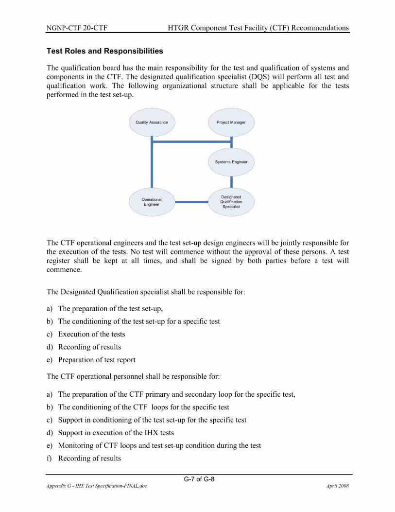
NGNP-CTF 20-CTF HTGR Component Test Facility (CTF) Recommendations
G-7 of G-8 Appendix G - IHX Test Specification-FINAL.doc April 2008
Test Roles and Responsibilities
The qualification board has the main responsibility for the test and qualification of systems and components in the CTF. The designated qualification specialist (DQS) will perform all test and qualification work. The following organizational structure shall be applicable for the tests performed in the test set-up.
Quality Assurance Project Manager
Systems Engineer
Designated Qualification
Specialist
Operational Engineer
The CTF operational engineers and the test set-up design engineers will be jointly responsible for the execution of the tests. No test will commence without the approval of these persons. A test register shall be kept at all times, and shall be signed by both parties before a test will commence.
The Designated Qualification specialist shall be responsible for:
a) The preparation of the test set-up,
b) The conditioning of the test set-up for a specific test
c) Execution of the tests
d) Recording of results
e) Preparation of test report
The CTF operational personnel shall be responsible for:
a) The preparation of the CTF primary and secondary loop for the specific test,
b) The conditioning of the CTF loops for the specific test
c) Support in conditioning of the test set-up for the specific test
d) Support in execution of the IHX tests
e) Monitoring of CTF loops and test set-up condition during the test
f) Recording of results

NGNP-CTF 20-CTF HTGR Component Test Facility (CTF) Recommendations
G-8 of G-8 Appendix G - IHX Test Specification-FINAL.doc April 2008
g) Supply of results to the Designated Qualification specialist in paper or electronic format.
Safety Requirements and Considerations
The following will be required for test personnel.
a) All test personnel must use safety clothes
b) All relevant safety regulations and special conditions must be followed.
Calibration and Measurements
All temperature sensors/gauges, pressure sensors/gauges, flow meters and height measurement equipment shall be issued with a calibration certificate. The calibration certificates shall form part of the test report.
Test Documentation and Data
All test documentation and data for each test shall be available in paper or electronic format.
Test Report
A report will be generated after completion of the tests. The test report will include the results as well as recommendations (if any) to the design.