next generation digital back-ends at the gmrt yashwant gupta yashwant gupta national centre for...
TRANSCRIPT

Next Generation Digital Back-ends Next Generation Digital Back-ends at the GMRTat the GMRT
Yashwant GuptaYashwant Gupta
National Centre for Radio AstrophysicsNational Centre for Radio AstrophysicsPune IndiaPune India
CASPER meeting Cambridge 17th August 2010CASPER meeting Cambridge 17th August 2010

The GMRT : some basic factsThe GMRT : some basic facts The Giant Metre-wave Radio Telescope (GMRT) is an international facility operating at low The Giant Metre-wave Radio Telescope (GMRT) is an international facility operating at low
radio frequencies (50 to 1450 MHz) radio frequencies (50 to 1450 MHz)
Consists of 30 antennas of 45 metres diameter, spread out over a region of 30 km diameterConsists of 30 antennas of 45 metres diameter, spread out over a region of 30 km diameter
Currently operates with a max BW of 32 MHz at 5 different bands : 150, 235, 325, 610 Currently operates with a max BW of 32 MHz at 5 different bands : 150, 235, 325, 610 and 1420 MHzand 1420 MHz
Supports interferometry as well as array mode of operations Supports interferometry as well as array mode of operations correlator + beamformer + correlator + beamformer + pulsar receiver pulsar receiver
Operational and open to international participation since 2002; has about 40% users from Operational and open to international participation since 2002; has about 40% users from India, 60% from outside ; more than a factor of 2 oversubscribedIndia, 60% from outside ; more than a factor of 2 oversubscribed
14 km
1 km x 1 km

The GMRT : some basic factsThe GMRT : some basic facts The Giant Metre-wave Radio Telescope (GMRT) is an international facility operating at low The Giant Metre-wave Radio Telescope (GMRT) is an international facility operating at low
radio frequencies (50 to 1450 MHz) radio frequencies (50 to 1450 MHz)
Consists of 30 antennas of 45 metres diameter, spread out over a region of 30 km diameterConsists of 30 antennas of 45 metres diameter, spread out over a region of 30 km diameter
Currently operates with a max BW of 32 MHz at 5 different bands : 150, 235, 325, 610 Currently operates with a max BW of 32 MHz at 5 different bands : 150, 235, 325, 610 and 1420 MHzand 1420 MHz
Supports interferometry as well as array mode of operations Supports interferometry as well as array mode of operations correlator + beamformer + correlator + beamformer + pulsar receiver pulsar receiver
Operational and open to international participation since 2002; has about 40% users from Operational and open to international participation since 2002; has about 40% users from India, 60% from outside ; more than a factor of 2 oversubscribedIndia, 60% from outside ; more than a factor of 2 oversubscribed

Upgrading the GMRTUpgrading the GMRT
The GMRT has already produced some interesting results and, even in the The GMRT has already produced some interesting results and, even in the current configuration, will function as a competitive instrument for some more current configuration, will function as a competitive instrument for some more years.years.
However, we are working on an upgrade, with focus on :However, we are working on an upgrade, with focus on :
Seamless frequency coverage fromSeamless frequency coverage from ~ 30 MHz to 1500 MHz, ~ 30 MHz to 1500 MHz, instead of the instead of the limited bands at presentlimited bands at present design of completely new feeds and receiver design of completely new feeds and receiver system.system.
Improved G/Tsys byImproved G/Tsys by reduced system temperature reduced system temperature better technology better technology receiversreceivers
Increased Increased instantaneous bandwidth of 400 MHz instantaneous bandwidth of 400 MHz (from the present (from the present maximum of 32 MHz)maximum of 32 MHz) modern new digital back-end receiver modern new digital back-end receiver
Revamped servo system for the antennas Revamped servo system for the antennas
Modern and more versatile control and monitor systemModern and more versatile control and monitor system
Matching improvements in offline computing facilities and other infrastructureMatching improvements in offline computing facilities and other infrastructure

Development of new back-ends for the Development of new back-ends for the
GMRTGMRT The GMRT Software Back-end (GSB) -- with CITA The GMRT Software Back-end (GSB) -- with CITA
GMRT Transient Analysis Pipeline : GSB + GPUs -- with SwinburneGMRT Transient Analysis Pipeline : GSB + GPUs -- with Swinburne
300 MHz Wideband Pocket Correlator on the Roach -- with 300 MHz Wideband Pocket Correlator on the Roach -- with CASPER + SKA-SACASPER + SKA-SA
Packetised Correlator for 400 MHz, 4 antennas, dual pol -- with Packetised Correlator for 400 MHz, 4 antennas, dual pol -- with CASPER + SKA-SACASPER + SKA-SA
GPU based correlator -- with Swinburne GPU based correlator -- with Swinburne
For existing For existing 32 MHz 32 MHz systemsystem
For 400 For 400 MHz MHz
GMRT GMRT upgrade upgrade systemsystem

The GMRT Software Back-end (GSB)The GMRT Software Back-end (GSB)
Software based back-ends :Software based back-ends : Few made to order hardware components ; Few made to order hardware components ;
mostly off-the-shelf items mostly off-the-shelf items Easier to program ; more flexible Easier to program ; more flexible
GMRT Software Back-end (GSB) GMRT Software Back-end (GSB) :: 32 antennas32 antennas 32 MHz bandwidth, dual pol32 MHz bandwidth, dual pol Net input data rate : 2 Gsamples/sec Net input data rate : 2 Gsamples/sec FX correlator + beam former FX correlator + beam former Uses off-the-shelf ADC cards, CPUs & switches Uses off-the-shelf ADC cards, CPUs & switches
to implement a to implement a fully real-time back-endfully real-time back-end Raw voltage recording to disks, for all antennas; Raw voltage recording to disks, for all antennas;
off-line read back & analysis off-line read back & analysis Currently status : completed and released as Currently status : completed and released as
observatory facilityobservatory facilityJayanta Roy et al (2010)Jayanta Roy et al (2010)

The GMRT software backend : The GMRT software backend : block diagramblock diagram
Jayanta Roy et al (2010)Jayanta Roy et al (2010)


GSB Software flow : real-time modeGSB Software flow : real-time mode
PAPABeamBeam
IAIABeamBeamADCADC
16 MHz16 MHzor or
32 MHz32 MHz
(with (with AGC)AGC)
Int Int Delay Delay CorrectCorrect
Filter Filter ++
DesampDesamp
FFTFFT++
FSTC FSTC & &
FringeFringeMACMAC
BeamBeamformerformer
visibilitiesvisibilities
64 analog64 analogInputsInputs
(32 ants, (32 ants, 2 pols)2 pols)


GSB : Performance OptimisationGSB : Performance Optimisation
Network transfer optimisation : jumbo packets Network transfer optimisation : jumbo packets
Computation optimisation : Computation optimisation : Intel IPP routines (for FFT)Intel IPP routines (for FFT) Vectorised operationsVectorised operations Cache optimisationCache optimisation Multi-threading load balancingMulti-threading load balancing
Performance specs :Performance specs : Better than 85% compute efficiencyBetter than 85% compute efficiency $190 / baseline ; 250 Mflops / W$190 / baseline ; 250 Mflops / W
Jayanta Roy et al (2010)Jayanta Roy et al (2010)

GSB Sample Results : ImagingGSB Sample Results : Imaging
J1609+266 calibrator J1609+266 calibrator field at 1280 MHzfield at 1280 MHz
8.5 hrs synthesis image8.5 hrs synthesis image
Central source : 4.83 JyCentral source : 4.83 Jy
Noise level at HPBW : Noise level at HPBW : 34 microJy34 microJy
Dynamic range achieve : Dynamic range achieve : ~ 1.5 x10~ 1.5 x1055

GSB Sample Results : GSB Sample Results : BeamformingBeamforming
Phasing the array using a point Phasing the array using a point source calibratorsource calibrator
Single pulses from PSR B0329+54Single pulses from PSR B0329+54

New Capabilities : RFI mitigationNew Capabilities : RFI mitigation
MAD filtering on raw time resolution data to eliminate bursty, MAD filtering on raw time resolution data to eliminate bursty, time domain RFI : works very nicelytime domain RFI : works very nicely
Jayanta Roy et al (2010)Jayanta Roy et al (2010)
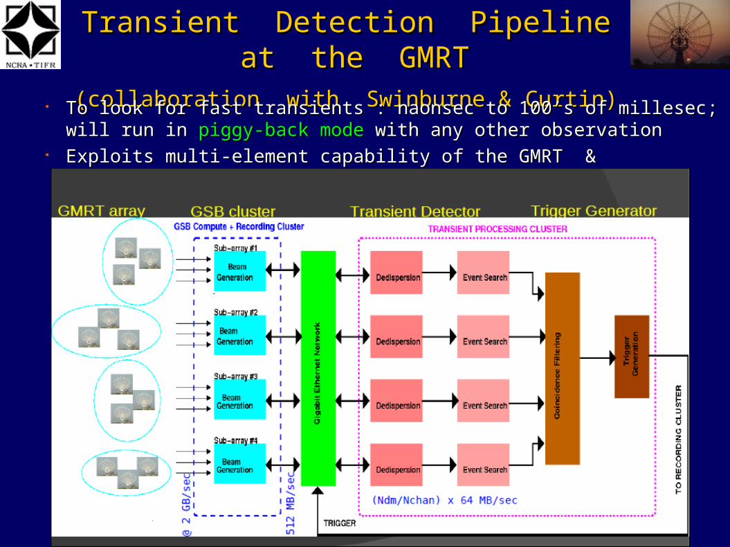
Transient Detection Pipeline at the GMRTTransient Detection Pipeline at the GMRT(collaboration with Swinburne & Curtin)(collaboration with Swinburne & Curtin)
To look for fast transients : naonsec to 100’s of millesec; will run in To look for fast transients : naonsec to 100’s of millesec; will run in piggy-back modepiggy-back mode with any other observationwith any other observation
Exploits multi-element capability of the GMRT & availability of software backendExploits multi-element capability of the GMRT & availability of software backend

Transient Detection Pipeline at the GMRTTransient Detection Pipeline at the GMRT
Event detection : based on the sensitivity of 8 antennae incoherent array beam over 32 Event detection : based on the sensitivity of 8 antennae incoherent array beam over 32 MHz, using multiple sub-arrays MHz, using multiple sub-arrays
Coincidence or anti-coincidence filter : Coincidence or anti-coincidence filter : Multiple sub-array multiple beam coincidenceMultiple sub-array multiple beam coincidence filterfilter reduces the false triggers due to noise or RFI reduces the false triggers due to noise or RFI

Transient Detection Pipeline at the GMRTTransient Detection Pipeline at the GMRT
CPU + Tesla CPU + Tesla GPUGPU
Search in dispersion measure space : Discriminate fast radio transients from RFISearch in dispersion measure space : Discriminate fast radio transients from RFI Real-time trigger generation accompanied by recording of identified raw voltage data Real-time trigger generation accompanied by recording of identified raw voltage data
buffers buffers off-line detailed imaging analysisoff-line detailed imaging analysis to localise the transient source to localise the transient source

GPUs for Incoherent Dedispersion GPUs for Incoherent Dedispersion
Each CPU-GPU combination handles data from one sub-array beam from the GSB : Each CPU-GPU combination handles data from one sub-array beam from the GSB : 256 channels across 32 MHz, 15 microsec time resolution 256 channels across 32 MHz, 15 microsec time resolution
Data is buffered into a shared memory, is read out and passed to the GPU in Data is buffered into a shared memory, is read out and passed to the GPU in overlapping blocks overlapping blocks
GPU does dedispersion for multiple DMs in real-time and sends the dedispersed time GPU does dedispersion for multiple DMs in real-time and sends the dedispersed time series back to the CPUseries back to the CPU
Benchmarks : 256 chans, 32 MHz bandwidth, 15 microsec sampling, 1 to 5 sec dataBenchmarks : 256 chans, 32 MHz bandwidth, 15 microsec sampling, 1 to 5 sec data
single Tesla can do upto 1000 DMs at real time ratesingle Tesla can do upto 1000 DMs at real time rate
(collaboration with Swinburne University of Technology)(collaboration with Swinburne University of Technology)

GMRT Upgrade : Digital Backend GMRT Upgrade : Digital Backend RequirementsRequirements
Specifications :Specifications : 30 stations30 stations 400 MHz BW (instantaneous)400 MHz BW (instantaneous) 8 - 16 K Freq Channels 8 - 16 K Freq Channels Full polar mode Full polar mode Coarse and Fine Delay correctionCoarse and Fine Delay correction Fringe rotationFringe rotation Interferometer with dump times ~ 100 msInterferometer with dump times ~ 100 ms Incoherent and Phased array beam outputs : at least 2 Incoherent and Phased array beam outputs : at least 2
beams for each; with full time resolutionbeams for each; with full time resolution Pulsar back-ends attached to the beam outputsPulsar back-ends attached to the beam outputs
Approach :Approach : FPGA based system using Roach boards ( starting with the FPGA based system using Roach boards ( starting with the
PoCo )PoCo ) Hybrid back-end using FPGA + CPU-GPU units Hybrid back-end using FPGA + CPU-GPU units

Sample Results : wideband PoCoSample Results : wideband PoCo
2 antenna, 300 MHz BW 2 antenna, 300 MHz BW wideband Pocket Correlator wideband Pocket Correlator on Roach boardon Roach board
Full delay correction Full delay correction (integer and fractional (integer and fractional sample)sample)
Fringe correction Fringe correction
Tested with wideband Tested with wideband signals from GMRT signals from GMRT antennas antennas

Sample Results : wideband PoCoSample Results : wideband PoCo
2 antenna, 300 MHz BW 2 antenna, 300 MHz BW wideband Pocket Correlator wideband Pocket Correlator on Roach boardon Roach board
Full delay correction Full delay correction (integer and fractional (integer and fractional sample) sample)
Fringe correction Fringe correction
Tested with wideband Tested with wideband signals from GMRT signals from GMRT antennas antennas

Antenna 32Antenna 32(400 MHz(400 MHz
2 pols)2 pols)
ADCADC(2 channels)(2 channels)
Roach Roach (F engine)(F engine)
Roach Roach (X engine)(X engine)
Packetised Correlator DesignPacketised Correlator Design (collaboration with SKA-SA + CASPER)(collaboration with SKA-SA + CASPER)
SwitchSwitch(10 Gbe)(10 Gbe)
Antenna 1Antenna 1(400 MHz(400 MHz
2 pols)2 pols)
ADCADC(2 channels)(2 channels)
Roach Roach (F engine)(F engine)
Roach Roach (X engine)(X engine)
Antenna 2Antenna 2(400 MHz(400 MHz
2 pols)2 pols)
ADCADC(2 channels)(2 channels)
Roach 2Roach 2(F engine)(F engine)
Roach Roach (X engine)(X engine)
Data Acquisition Data Acquisition and Controland Control
Roach Roach (X engine)(X engine)
Roach Roach (X engine)(X engine)
Roach Roach (X engine)(X engine)

First Results from Packetised First Results from Packetised
Correlator at the GMRTCorrelator at the GMRT 4 antenna, dual pol, 400 4 antenna, dual pol, 400
MHz packetised correlatorMHz packetised correlator
2 F engine Roach boards2 F engine Roach boards
4 X engine Roach boards4 X engine Roach boards
Delay correction testedDelay correction tested
Fringe correction tested Fringe correction tested
Collaboration with Collaboration with SKA-SA teamSKA-SA team
1111thth August August 2010 !2010 !

Software Correlator DesignSoftware Correlator Design (collaboration with Swinburne)(collaboration with Swinburne)
SwitchSwitch(10 Gbe)(10 Gbe)
Data Acquisition Data Acquisition and Controland Control
CPU + GPUCPU + GPU(F+X engine)(F+X engine)
CPU + GPUCPU + GPU(F+X engine)(F+X engine)
CPU + GPU CPU + GPU (F+X engine)(F+X engine)
Antenna 1Antenna 1(400 MHz(400 MHz
2 pols)2 pols)
ADCADC(2 channels)(2 channels)
CPU + GPU machineCPU + GPU machine(F + X engine)(F + X engine)
Antenna 1Antenna 1(400 MHz(400 MHz
2 pols)2 pols)
ADCADC(2 channels)(2 channels)
CPU + GPU machineCPU + GPU machine(F + X engine)(F + X engine)
Antenna 1Antenna 1(400 MHz(400 MHz
2 pols)2 pols)
ADCADC(2 channels)(2 channels)
CPU + GPU machineCPU + GPU machine(F + X engine)(F + X engine)

First Results from GPU Correlator at First Results from GPU Correlator at
the GMRTthe GMRT 2 antenna, 200 MHz design2 antenna, 200 MHz design
iADC + iBoB sending data at 800 iADC + iBoB sending data at 800 Mbytes/sec to a Nehelam CPU Mbytes/sec to a Nehelam CPU
Data written to shared memory ring Data written to shared memory ring buffer after on-the-fly delay buffer after on-the-fly delay correctioncorrection
Data read from shared memory and Data read from shared memory and sent to GPU for FFT + MAC sent to GPU for FFT + MAC operations operations
Collaboration with Collaboration with Swinburne team Swinburne team
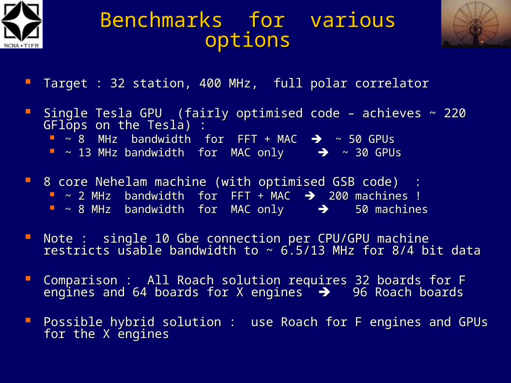
Benchmarks for various optionsBenchmarks for various options
Target : 32 station, 400 MHz, full polar correlatorTarget : 32 station, 400 MHz, full polar correlator
Single Tesla GPU (fairly optimised code – achieves ~ 220 GFlops on the Tesla) : Single Tesla GPU (fairly optimised code – achieves ~ 220 GFlops on the Tesla) : ~ 8 MHz bandwidth for FFT + MAC ~ 8 MHz bandwidth for FFT + MAC ~ 50 GPUs ~ 50 GPUs ~ 13 MHz bandwidth for MAC only ~ 13 MHz bandwidth for MAC only ~ 30 GPUs ~ 30 GPUs
8 core Nehelam machine (with optimised GSB code) : 8 core Nehelam machine (with optimised GSB code) : ~ 2 MHz bandwidth for FFT + MAC ~ 2 MHz bandwidth for FFT + MAC 200 machines ! 200 machines ! ~ 8 MHz bandwidth for MAC only ~ 8 MHz bandwidth for MAC only 50 machines 50 machines
Note : single 10 Gbe connection per CPU/GPU machine restricts usable bandwidth Note : single 10 Gbe connection per CPU/GPU machine restricts usable bandwidth to ~ 6.5/13 MHz for 8/4 bit datato ~ 6.5/13 MHz for 8/4 bit data
Comparison : All Roach solution requires 32 boards for F engines and 64 boards for Comparison : All Roach solution requires 32 boards for F engines and 64 boards for X engines X engines 96 Roach boards 96 Roach boards
Possible hybrid solution : use Roach for F engines and GPUs for the X engines Possible hybrid solution : use Roach for F engines and GPUs for the X engines

Antenna 32Antenna 32(400 MHz(400 MHz
2 pols)2 pols)
ADCADC(2 channels)(2 channels)
Roach Roach (F engine)(F engine)
CPU + GPU CPU + GPU (X engine)(X engine)
Hybrid Correlator DesignHybrid Correlator Design
SwitchSwitch(10 Gbe)(10 Gbe)
Antenna 1Antenna 1(400 MHz(400 MHz
2 pols)2 pols)
ADCADC(2 channels)(2 channels)
Roach Roach (F engine)(F engine)
CPU + GPUCPU + GPU(X engine)(X engine)
Antenna 2Antenna 2(400 MHz(400 MHz
2 pols)2 pols)
ADCADC(2 channels)(2 channels)
Roach 2Roach 2(F engine)(F engine)
CPU + GPU CPU + GPU (X engine)(X engine)
Data Acquisition Data Acquisition and Controland Control
CPU + GPU CPU + GPU (X engine)(X engine)
CPU + GPU CPU + GPU (X engine)(X engine)
CPU + GPUCPU + GPU(X engine)(X engine)

Benchmarks for various optionsBenchmarks for various options
Target : 32 station, 400 MHz, full polar correlatorTarget : 32 station, 400 MHz, full polar correlator
Single Tesla GPU : Single Tesla GPU : ~ 8 MHz bandwidth for FFT + MAC ~ 8 MHz bandwidth for FFT + MAC ~ 50 GPUs ~ 50 GPUs ~ 13 MHz bandwidth for MAC only ~ 13 MHz bandwidth for MAC only ~ 30 GPUs ~ 30 GPUs
8 core Nehelam machine (with optimised GSB code) : 8 core Nehelam machine (with optimised GSB code) : ~ 2 MHz bandwidth for FFT + MAC ~ 2 MHz bandwidth for FFT + MAC 200 machines ! 200 machines ! ~ 8 MHz bandwidth for MAC only ~ 8 MHz bandwidth for MAC only 50 machines 50 machines
Note : single 10 Gbe connection per CPU/GPU machine restricts usable bandwidth to ~ 6.5/13 Note : single 10 Gbe connection per CPU/GPU machine restricts usable bandwidth to ~ 6.5/13 MHz for 8/4 bit dataMHz for 8/4 bit data
Comparison : All Roach solution requires 32 boards for F engines and 64 boards for X engines Comparison : All Roach solution requires 32 boards for F engines and 64 boards for X engines 96 Roach boards 96 Roach boards
Possible hybrid solution : use Roach for F engines and GPUs for the X enginesPossible hybrid solution : use Roach for F engines and GPUs for the X engines Hybrid solution also useful for recording of raw voltages for special modes of Hybrid solution also useful for recording of raw voltages for special modes of
observations, test and debug purposes etc. observations, test and debug purposes etc.


Talk Layout Talk Layout GMRT intro – 2 slides : OKGMRT intro – 2 slides : OK GMRT current specs : RF, BW, back-end – needs one more slide?GMRT current specs : RF, BW, back-end – needs one more slide? GMRT upgrade overview : needs some mods?GMRT upgrade overview : needs some mods? Outline of GMRT back-end development (along with collaborations)Outline of GMRT back-end development (along with collaborations) Development of back-ends : part I : GSBDevelopment of back-ends : part I : GSB Transient analysis pipeline with GSB Transient analysis pipeline with GSB GPU based processing GPU based processing Specs for upgrade back-end ; FPGA & hybrid possibilities Specs for upgrade back-end ; FPGA & hybrid possibilities Sample results from wideband PoCo : with delay and fringe tracking ; longest Sample results from wideband PoCo : with delay and fringe tracking ; longest
sequence of fringe stopped data? pics ?sequence of fringe stopped data? pics ? 32 ant, 400 MHz, full polar, BE layout : general architecture32 ant, 400 MHz, full polar, BE layout : general architecture All FPGA architecture ; SA collaborationAll FPGA architecture ; SA collaboration Hybrid architecture ; Swinburne collaborationHybrid architecture ; Swinburne collaboration Some results :: Some results ::
Wideband PoCo on Roach : with delay and fringe correctionWideband PoCo on Roach : with delay and fringe correction 4 ant packetised design with delay and fringe correction 4 ant packetised design with delay and fringe correction 2 ant, 200 MHz, iBoB + GPU design ; CPU benchmarsk also ? 2 ant, 200 MHz, iBoB + GPU design ; CPU benchmarsk also ?
Some numbers :Some numbers : 32 station, all Roach design32 station, all Roach design 32 stations, CPU-GPU design32 stations, CPU-GPU design Designs with raw voltage recordingDesigns with raw voltage recording Future ProspectsFuture Prospects

Software flow : real-time mode Software flow : real-time mode
64 analog64 analogInputsInputs
(32 ants, 2 (32 ants, 2 pols)pols)