the upgraded gmrt : opening new...
TRANSCRIPT

The upgraded GMRT :
Opening new windows
Yashwant Gupta
National Centre for Radio Astrophysics
Pune India
PHISC meeting NCRA Pune 6 Feb 2017

Plan of today's presentation
The upgraded GMRT (uGMRT) – goals & plans
Developments & current status of different aspects of the uGMRT
Status of (phased) release of the uGMRT to the user community

The existing GMRT : An Overview
30 dishes, 45 m diameter each 12 dishes in a central 1 km x 1 km region
(central square) remaining along 3 arms of Y-shaped array baselines : ~ 200 m (shortest);
~ 30 km (longest) Frequency range :
130-170 MHz 225-245 MHz 300-360 MHz 580-660 MHz 1000-1450 MHz max instantaneous BW = 32 MHz
Effective collecting area (2-3% of SKA) : 30,000 sq m at lower frequencies 20,000 sq m at highest frequencies
Supports 2 modes of operation : Interferometry, aperture synthesis Array mode (incoherent & coherent)
14
km
1 km x
1 km

Dedication of the GMRT
The Giant Metrewave Radio Telescope was dedicated to the World
Scientific Community by the Chairman of TIFR Council, Shri Ratan Tata.
October 4, 2001

GMRT : Usage Statistics
GMRT sees users from all over the world : distribution of Indian vs Foreign users is close to 45:55
The GMRT has been typically oversubscribed by a factor of 2 or more

GMRT : Scientific Objectives
The GMRT is a powerful instrument to probe several astrophysical
objects and phenomena :
The Sun, extrasolar planets
Pulsars : rapidly rotating neutron stars
Other Galactice objects like : supernova remnants, microquasars etc
Other explosive events like Gamma Ray Bursts
Ionized and neutral Hydrogen gas clouds (in our Galaxy and in other
galaxies)
Radio properties of different kinds of galaxies; galaxy clusters
Radio galaxies at large distances in the Universe
Cosmology and the Epoch of Reionization
All sky surveys such as the 150 MHz TGSS
…and many interesting new results have been produced

Next Generation : The uGMRT
For last several years the GMRT has been working well on the global stage; however, it was time to think of the future & upgrade the facility, keeping in mind technology development for global efforts such as the SKA.
Main goals for the upgraded GMRT (uGMRT) were identified as :
Seamless frequency coverage from ~ 50 MHz to 1500 MHz, instead of the limited bands at present design of completely new feeds and receiver systems with ~ octave bandwidths
Improved dynamic range and G/Tsys better technology receivers
Increased instantaneous bandwidth of 400 MHz (from the present maximum of 32 MHz) new digital back-end receiver
Revamped servo system brushless drives, new servo computer etc
Modern, versatile control and monitor system SKA contribution
Matching improvements in offline computing facilities
Improvements in mechanical & electrical systems, infrastructure facilities
To be done without compromising availability of existing GMRT to users

uGMRT : Expected Performance
Expected sensitivity performance of the
upgraded GMRT compared to other major
facilities in the world, present and projected
(courtesy : Nissim Kanekar, NCRA)
Spectral lines : broadband
coverage will give significant
increase in the redshift space for
HI lines + access to other lines
Continuum imaging sensitivity will
improve by factor of 3 or so.
Sensitivity for pulsar observations
will also improve by factor of 3.
Only SKA-I will do better then
uGMRT at centimeter wavelengths

Overview of uGMRT Receiver System
Broad-band feeds + FE (in octaves) :
1000 – 1450 MHz (updating L-band)
550 – 900 MHz (replacing 610)
250 – 500 MHz (replacing 325)
120 – 250 MHz (replacing 150)
Modified optical fibre system to cater
to wideband (50 to 2000 MHz) dual
pol RF signals (while allowing
existing IF signals)
Analog back-end system to translate
RF signals to 0 - 400 MHz baseband
Digital back-end system process 400
MHz BW for interferometric and
beam modes

Wideband feeds + FE for uGMRT :
550-900 MHz system – “Band 4”
Replaces existing 235/610 system
Front-End system split into two parts :
Polariser + LNA is right next to feed (to
minimize the loss)
Rest of the FE electronics is in the regular box
Now installed on 12 antennas and growing…
Cone Dipole feed
(for 550-900)
alongwith polarizer
and LNA

Wideband feeds + FE for uGMRT :
550-900 MHz system – “Band 4”
Performs better than existing feed at 610 MHz
Nice, clean band with negligible RFI

uGMRT : New Wideband Systems
Summary
Proposed configuration of feeds and receivers and their current status :
Band 5 (1000 – 1450 MHz ) : existing wideband feed + improved dynamic
range rx with appropriate RFI filters -- completed on 30 antennas !
Band 4 (550 – 900 MHz) : cone-dipole feed with matching receiver system
finalized and now in mas production phase -- 10 antennas completed.
Band 3 (250 – 500 MHz) : cone-dipole feed + receiver is well into mass
production & installation -- 30 antennas completed !
Band 2 (120 – 250 MHz) : modified Kildal ring feed + modified electronics
in last stages of validation – populated on 4 antennas.
Band 1 (50 – 80 MHz) : on hold at present.

GMRT vs uGMRT : Frequency Coverage
courtesy : Ruta Kale

Overview of uGMRT Receiver System
Broad-band feeds + FE (in octaves) :
120 – 250 MHz (replacing 150)
250 – 500 MHz (replacing 325)
550 – 900 MHz (replacing 610)
1000 – 1450 MHz (updating L-band)
Modified optical fibre system to cater
to wideband (50 to 2000 MHz) dual
pol RF signals (while allowing
existing IF signals)
Analog back-end system to translate
RF signals to 0 - 400 MHz baseband
Digital back-end system process 400
MHz BW for interferometric and
beam modes

uGMRT Digital Backend :
Hybrid Correlator Design
Antenna 32
(400 MHz
2 pols)
ADC
(2channels)
FPGA
(packetizer)
CPU + GPU
(correlator)
Switch
(40 Gbe)
Antenna 1
(400 MHz
2 pols)
ADC
(2channels)
FPGA
(packetizer)
CPU + GPU
(correlator)
Antenna 2
(400 MHz
2 pols)
ADC
(2channels)
FPGA
(packetizer)
CPU + GPU
(correlator)
Data Acquisition
and Control
CPU + GPU
(correlator)
CPU + GPU
(correlator)
CPU + GPU
(correlator)
32 stations, 400 MHz BW, 16-32 K channels,
Full Stokes correlator + beamformer + pulsar rx.

GWB-III : 16 antenna (dual poln) 400 MHz
software backend for the uGMRT
8-node GPU system
16 ADC cards + 8 FPGA boards
Dual K20 GPUs on each T620 node
Released in September 2015
BW : 400 MHz, upto 16K channels
Int Time : 0.67 sec
IA/PA Beamformer
Upgrade to 32 stations by Dec 2016

Towards a working
uGMRT…

GHB: 4 hrs, BW: 14 MHz, rms=55 microJy/beamGWB: 2 hrs, BW: 250 MHz, rms=30 microJy/beam
uGMRT : Early Sample Results
courtesy : C.H. Ishwara-Chandra + Binny Sebastian
Imaging with the 400 MHz bandwidth mode at Lband

3C129 imaged with the uGMRT system using 14 antennas, 300-500 MHz
uGMRT : Early Sample Results
courtesy : Dharam Vir Lal
+ Binny Sebastian
• 80 microJy
• 3 hours
• 14 antennas
• 300-500 MHz
• Calibration in AIPS
• Imaging in CASA
• W-projection
• MS-MFS
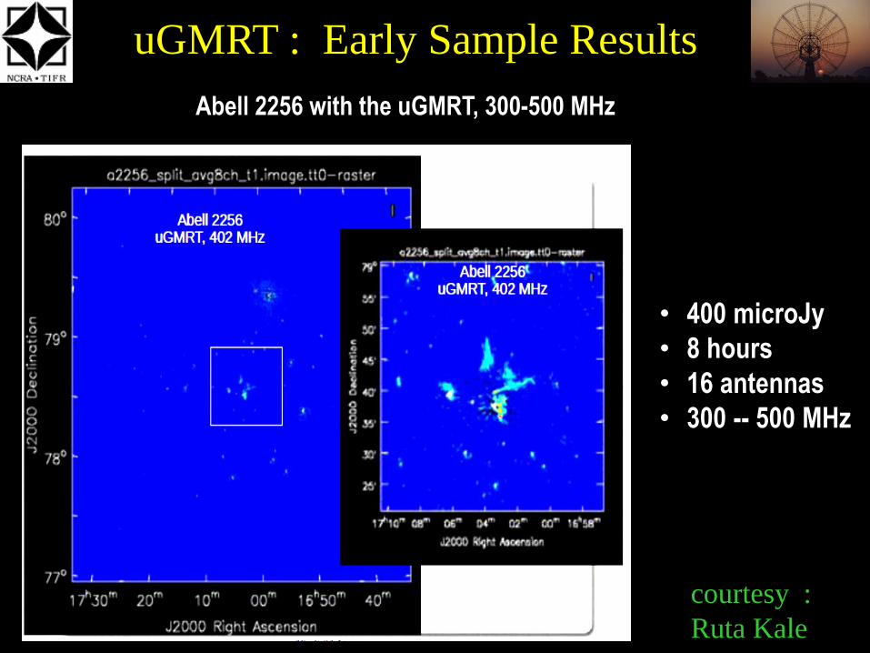
uGMRT : Early Sample Results
courtesy :
Ruta Kale
Abell 2256 with the uGMRT, 300-500 MHz
• 400 microJy
• 8 hours
• 16 antennas
• 300 -- 500 MHz

uGMRT : Early Sample Results
courtesy : Ishwar-Chandra
A85 relic with the uGMRT, 300-500 MHz
• 16 antennas
• 2048 channels
• 200 MHz bandwidth
• 6 x 20 min
• rms ~0.9 mJy/beam
• beam 6.5 arcsec

Pulsars uGMRT : sample profiles
• J1455-3330
• S_1400 = 1.2 mJy
• Band-5 (1260 to 1460 MHz)
• 10 mins scan
• 12 antennas

Pulsars with uGMRT : sample profiles
• MSP : J1455-3330
• S_400 = 9 mJy
• Band-3 (300 to 500 MHz)
• 10 mins scan
• 4 antennas (only)

Wideband pulsar observations : improved sensitivity
PSR B1508+55
120 MHz at Lband (1330-1450)
vs
33 MHz at Lband (1390 sub-band)
Simultaneous observations using
same # of antennas in phased array
mode.

Precision timing with the uGMRT
Regular timing observations for a few well known MSPs
Simultaneous observations using legacy and upgraded GMRT
Now extended to simultaneous dual-frequency observations with uGMRT : Band-5 (1060-1260-1460 MHz) and Band-3 (300-500 MHz)
Should be able to extend to multi-frequency (3 bands) with 30 antennas

Pulsar timing results with uGMRT
courtesy : Nikhil Naik & Y. Gupta
Timing residuals for MSP J0751+1807 : ~ 7 micro RMS
Timing residuals for MSP B1855+09 : ~ 2 micro RMS

Pulsar timing results with uGMRT
courtesy : Nikhil Naik & Y. Gupta
Timing residuals for dual frequency observations for MSP J1455-3330

Wideband Coherent Dedispersion for
the uGMRT
courtesy : Kishalay De & Y. Gupta
• Coherent Dedispersion on voltage
output of phased array mode of uGMRT
• Working in real-time (GPUs), for 100 to
200 MHz BWs, at low frequencies.
• Will be released soon for the general
user community.
• Will increase the quality of pulsar
timing with the uGMRT
Comparison of
regular phased array beam output
with
coherent dedispersion output
for 300 to 500 MHz band of the
uGMRT, for PSR J0613-0200

Upgraded GMRT : opening new
windows – Band 3 (250-500 MHz)
First light results : spectral lines from different sources, at different
parts of the 250-500 MHz band (Nissim Kanekar)

Upgraded GMRT : opening new
windows – Band 4 (550-850 MHz)
First light results : spectral lines from different sources, at different
parts of the 550-900 MHz band (Nissim Kanekar)

Challenges on the Road to uGMRT
The main challenges that we have encountered have been :
Technological : design of the wideband receiver systems was a
major challenge
Operational : keeping the existing GMRT working for our
regular users while upgrading simultaneously took some effort
Taking care of man made Radio Frequency Interference (RFI) is
and remains our biggest challenge !
Containing self generated RFI
Mitigating RFI from external sources :
(i) broadband impulsive (ii) spectral line

Avoiding RFI from satellites
Real-time prediction of positions of known satellites (stationary and moving)
Real-time warning when observing antenna beam comes within zone of
avoidance (decided by beamwidth and strength of satellite)
Predictive warning : can work on your submitted observing file
Post-facto warning : can work on your recorded data file

uGMRT : RFI Detection & Filtering
Real-time filter running on broadband voltage data of each antenna
Real-time spectral line filter running on spectra from each antenna
Real-time filter running on time-frequency visibility data (planned)
Real-time filter on time & frequency data of beamformer data stream.

54
RFI mitigation in digital domain
FPGA Implementation
RF @ 150MHz (Blue) and 3σ clipped (Red)
Median Absolute Deviation
(MAD) based flagging of RFI
Detection followed by filtering
and clipping the value at the
threshold or replacement with
random noise or median value
Can detect broadband random
noise spikes (e.g. powerline
RFI) in real-time on dedicated
FPGA hardware
Is being integrated into the
main correlator design; trial
version will be released soon.

Real-time RFI Detection & Filtering
Real-time filter running on broadband voltage data of each antenna
Top panel shows effect of this filtering, in beamformer time series
Bottom panels show effect of this filtering, in visibility domain data

Real-time RFI Detection & Filtering
Real-time filtering of time-frequency of beamformer data – now available
courtesy : A. Chowdhury
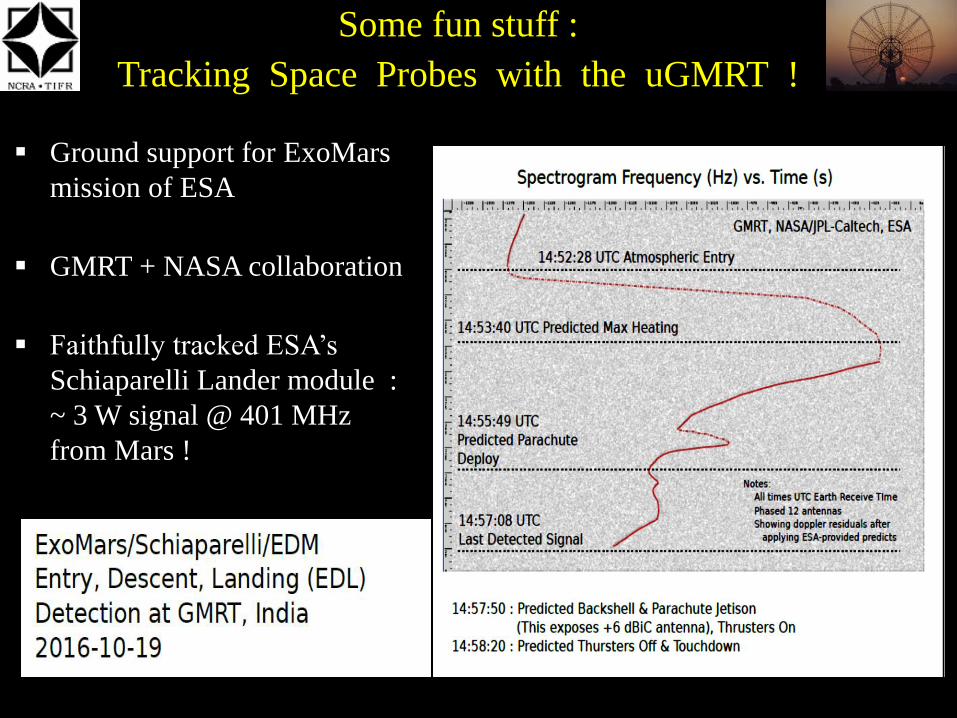
Some fun stuff :
Tracking Space Probes with the uGMRT !
Ground support for ExoMars
mission of ESA
GMRT + NASA collaboration
Faithfully tracked ESA’s
Schiaparelli Lander module :
~ 3 W signal @ 401 MHz
from Mars !

Release of uGMRT to Users
Releases in multiple phases :
1. First release of 8 antenna trial system – way back in September 2013.
2. Release of 16 antenna system for internal users – September 2015.
3. Release of 16 antenna system for all users -- April 2016 .
4. Now available : Release of a 30 antenna system with 2 bands fully functional : Band 5 (1000 to 1450 MHz) and Band 3 (250-500 MHz) -- October-November 2016 (GTAC Cycle 31)
5. In the future -- release of fully upgraded GMRT : 30 antenna configuration with all 4 bands fully functional --targeted for September / October 2017.
Stay tuned !

Thank You
Questions ?