new technology for wastewater control - niph.go.jp technology for wastewater control ... application...
TRANSCRIPT
New Technology for Wastewater Control
-Cutting-edge of Wastewater Treatment Technology-
Takao Murakami
R&D Dept., Japan Sewage Works Agency
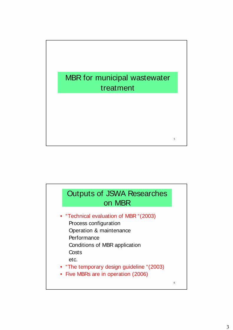
1. MBR for municipal wastewater treatment The membrane bioreactor (MBR) is a wastewater treatment technology that offers many
advantages. In Japan, although MBRs have long been used for industrial wastewater
treatment or for reuse of wastewater in large buildings and so on, the introduction of MBRs
in sewerage systems has lagged behind compared with other water related fields. However,
the first MBR for municipal wastewater treatment in Japan started operation in March 2005,
and this accelerated the introduction of MBRs in Japanese sewerage systems. Five MBR
plants for municipal wastewater treatment are in operation at present. In addition, there are
some 10 MBR plants currently in the design or planning stage. The number of MBRs for
municipal wastewater is expected to increase in the years ahead. Some fruits of research
work of JSWA about MBR are introduced to below.
Risk reduction of the water environment It is known that a high degree of virus removal could be achieved by MBR.[1] According to
our previous research, it was found that Colipharges and Norovirus of approximately
one-tenth membrane pore size were almost completely removed by a MF membrane. It
was also found that most of the virus existed in the activated sludge, indicating that they
attached themselves to the activated sludge. [2] It is suggested that the virus captured in
the gel layer that forms on the surface of the membrane also contribute to virus removal. [3]
Therefore it is considered that virus removal is influenced by the chemical cleaning of the
membrane.
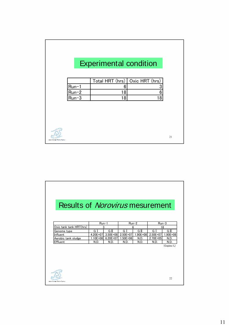
The behavior of Norovirus captured in the MBR activated sludge and the influence of the
chemical cleaning of the membrane was investigated using a pilot scale MBR which treats
48 m3/d of actual municipal wastewater. A hollow fiber MF membrane unit with 0.4µm
pore size was immersed in the oxic tank and operated at a permeate flux of 0.8 m3/m2/d.
The pilot plant was operated with a HRT of 6 hrs in Run-1, in which the oxic tank HRT was
3 hrs. During the experiment however, in order to evaluate the effect of the HRT on virus
removal, the total HRT was then extended to 18 hrs in which the oxic tank HRT was 6 hrs
in Run-2 and 18 hrs in Run-3 respectively.
5141 Shimo-sasame, Toda, Japan 335-0037, e-mail:[email protected]

The number of Norovirus in the activated sludge decreased with prolonged oxic tank HRT,
and the number of GⅠtype in Run –2 was about 1/1000 that of Run-1 as shown in Table 1.
Table 1. Norovirus measurement results for different aerobic tank HRT
This indicates that the aerobic decomposition of the virus, which was adsorbed in the
activated sludge and retained in the oxic tank, will progress with the elapse of time.
The number of Norovirus was measured at 30, 60, and 120 minutes after the in-line
chemical membrane cleaning using a 0.3% NaOCl solution. No Norovirus were detected
in the MBR effluent after the completion of chemical cleaning procedure. This may suggest
that the role of gel layer of the membrane surface on virus removal is less important than
the adsorption effect of the activated sludge.
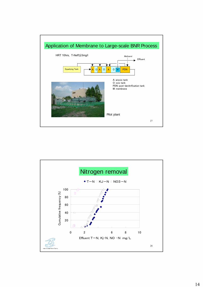
Application to BNR process Figure 1 shows a new biological nutrient removal (BNR) process for large facilities with
membrane separation.[4] This process combines the step feed multi-stage
nitrification-denitrification process, which is a popular BNR process in Japan, and
membrane separation. In a single-stage MBR, in order to obtain nitrogen removal efficiency
of more than 80%, circulation ratio of some 400% (R=4) is necessary.
Figure 1. Flow of the BNR process with membrane
Oxic tank tank HRT(hrs)
Genome type GⅠ GⅡ GⅠ GⅡ GⅠ GⅡInfluent 4.20E+07 3.50E+08 2.50E+07 1.90E+08 2.50E+07 1.90E+08Aerobic tank sludge 1.10E+08 6.20E+07 1.50E+06 N.D. 2.70E+05 N.D.Effluent N.D. N.D. N.D. N.D. N.D. N.D.
(Copies/L)
3 6 18Run-1 Run-2 Run-3
Effluent
A: anoxic tankO: oxic tankPDN: post-denitrification tankM: membrane
A O A O AEqualizing Tank O M
Methanol
PDN
However, in the membrane BNR process shown in Figure 1, a T-N removal efficiency of
about 80% is acquired at a circulation ratio of 200%. The experiment results showed that
stable nitrification and denitrification could be achieved even in low water temperature
period. Good and stable biological phosphorus removal can be achieved if the first anoxic
tank acts as an anaerobic tank. This is enabled by adding methanol to the
post-denitrification tank and eliminating NOx-N in the returned mixed liquor.
Perspective of the future development of MBR The MBR will not remain just one of many wastewater treatment technologies, but is
expected to become a core technology that will be used for various types of wastewater
management.
In Japan, MBR is expected to be increasingly used for municipal wastewater treatment.
Although the MBR has been used mainly for small scale plants so far, it will likely be
applied to larger plants in the future. To enable the wider use of MBR for various purposes,
the following issues are considered to be essential.
1) Optimization of the design method.
2) Optimization of the maintenance method, especially fouling control and chemical
cleaning of membrane.
3) Reduction of membrane cost and prolongation of membrane life.
4) Reduction of energy consumption, especially air supply for membrane cleaning.
JSWA will continue technology development of MBR in cooperation with universities and
private enterprises and will conduct the second technical evaluation of MBR based on the
data obtained from the five operating actual MBR plants in the near future.
2. Removal of EDCs by ozonation[5] Since the natural estrogens 17 β-estradiol (E2) and estron (E1), and the synthetic estrogen
17 α-ethynyl estradiol (EE2) have strong endocrine disrupting effects and the tendency to
persist in effluent from wastewater treatment plants, effective measures are needed to
remove them from wastewater.
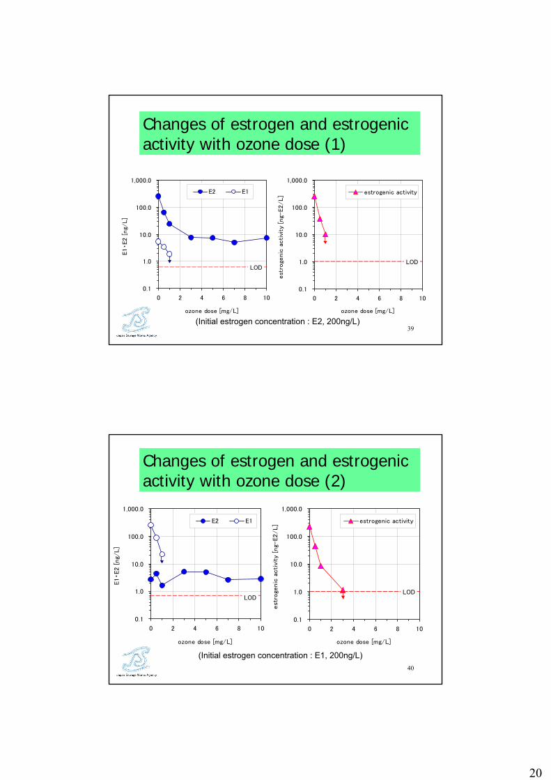
In our research, to gain an understanding of the characteristics of estrogen decomposition
by ozonation, experiments were conducted using effluent from an actual wastewater
treatment plant. In this experiment, estrogen was added to effluent at a concentration of
200 ng/l and 20ng/l before the ozonation experiments.
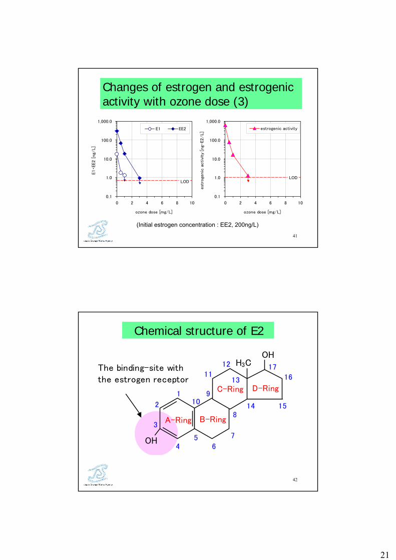
The results showed 90% or more of estrogen concentration and estrogenic activity of E2,
E1 and EE2 to be removed at an ozone dose of 1 mg/l as seen in Figure 2. At an ozone
dose of 3 mg/l, the estrogen concentration and estrogenic activity of E2, E1 and EE2 in the
treated water fell below the detection limit.

Figure 2. Changes of estrogen concentration and estrogenic activity with ozone dose.
Initial estrogen concentration: 200ng/l, contact time: 15min.
(Top row:E2 added, middle row:E1 added, bottom row:EE2 added)
The removal rate was not influenced by type of estrogen. No generation of byproducts with
estrogenic activity was observed. It is concluded that estrogen in secondary treated
wastewater can be almost entirely removed at the practical ozone dose rate applied for the
purpose of disinfection, which is up to about 5 mg/l.
0.1
1.0
10.0
100.0
1,000.0
0 2 4 6 8 10
ozone dose [m
E1・E2 [
ng/
L]
E2 E1
0.1
1.0
10.0
100.0
1,000.0
0 2 4 6 8 10
est
roge
nic
acti
vity
[ng-
E2/L]
estrogenic activity
0.1
1.0
10.0
100.0
1,000.0
0 2 4 6 8 10
E1・EE2 [
ng/
L]
E1 EE2
0.1
1.0
10.0
100.0
1,000.0
0 2 4 6 8 10
est
roge
nic
acti
vity
[ng-
E2/L]
estrogenic activity
0.1
1.0
10.0
100.0
1,000.0
0 2 4 6 8 10
E1・E2 [
ng/
L]
E2 E1
0.1
1.0
10.0
100.0
1,000.0
0 2 4 6 8 10
est
roge
nic
acti
vity
[ng-
E2/L]
estrogenic activity
Ozone dose [mg/l] Ozone dose [mg/l]
Ozone dose [mg/l] Ozone dose [mg/l]
Ozone dose [mg/l] Ozone dose [mg/l]
3. New biological nitrogen removal method –annamox process- The biological nitrification-denitrification process is widely used for nitrogen removal from
municipal wastewater. The annamox reaction is a biological nitrogen removal reaction
that completely differs from usual nitrification-denitrification as expressed by the following
chemical reaction.
1.0NH4++1.32NO2
-+0.066HCO3-+0.13H+→1.02N2+0.26NO3
-+0.066CH2O0.5N0.15+2.03H2O
Under the anaerobic conditions, ammoniac nitrogen and nitrite react producing nitrogen
gas.
The bacteria which participate in the reaction are called annamox bacteria and they are
tinged with peculiar red color.
There are following merits in the annamox reaction as compared with the conventional
nitrification-denitrification reaction.
1) Since about the half of ammoniac nitrogen in wastewater has to be converted into
nitrite, the required oxygen amount is theoretically about 50% of that of the
conventional nitrification-denitrification process.
2) Since the biological reaction is an autotrophic reaction, carbon source for denitirfication
is not necessary.
3) The excess sludge production is small by the same reason.
On the other hand, there are following subjects remaining to be solved.
1) Since the growth rate of annamox bacteria is low, enrichment of bacterial culture is not
easy in starting-up of the plant.
2) Applicable conditions are limited to wastewater with relatively high ammonia
concentration, low C/N ratio and high water temperature.
3) The stable conversion of half of the ammoniac nitrogen in the wastewater into nitrite is
essential as the preceding procedure.
It is supposed that the annamox process is suitable to treat sidestreams from anaerobic
digester or from deodorization equipment of sludge drying process. Especially the
reduction of nitrogen load of sidestreams from sludge treatment process will enable good
and stable performance of biological nitrogen removal process. JSWA is carrying a
research on the utilization of the annamox process including a joint research with private
companies.

References [1] Ottoson,J., Hansen,A., Bjorlenius,B., et al, “Removal of Viruses, Parasitic Protozoa
and Microbial Indicators in Conventional and Membrane Processes in a Wastewter Pilot
Plant”
Water Research 40 (2006) 1449-1457
[2] Oota,S., Murakami, T.,Takemura, K. and Noto, K. “Evaluation of MBR Effluent
Characteristics for Reuse Purposes” Water Science & Technology Vol. 51 No6-7
pp441-446, 2005
[3] Ueda,T.,Horan,N.j.,”Fate of Indigenous Bacteriophage in a Membrane Bioreactor”
Water Research 34 (2000) 2151-2159
[4] Oota,S., Murakami, T., and Uriu, M. “Advanced BNR Process Combined with
Membrane Separation”, Proceeding of IWA Asia-Pacific Regional Conference “Aspire 2005”
(CD-ROM), July 2005
[5] Hashimoto,T., Takahashi, k., and Murakami, T. “Characteristics of estrogen
decomposition by ozonation”, Water Science & Technology Vol. 54 No.10 pp87-93, 2006
1
1
New Technology for Wastewater ControlNew Technology for Wastewater Control
-Cutting-edge of Wastewater Treatment Technology-
Takao Murakami
R&D Dept., Japan Sewage Works Agency
2006.1.24
2
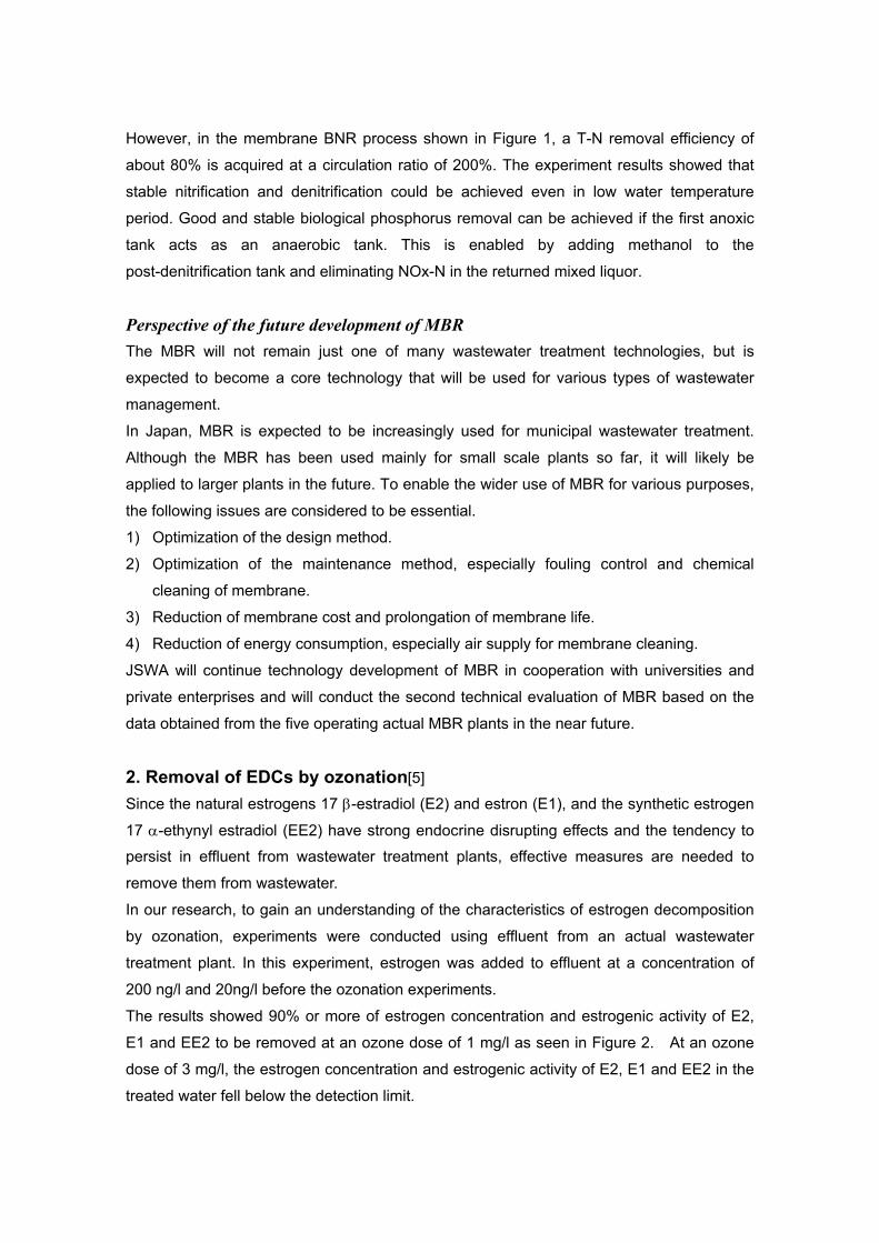
Introduction of JSWA• Public organization established by the
government and local municipalities• Purpose: Support local municipalities in
sewage works• Activities
Planning/Design/Construction of WTPsTechnical assistance Training of local municipality staff
Research & Development

2
3
JSWA Mouka research center
4
1. MBR for municipal wastewater treatment
2. Removal of EDCs by ozonation3. New biological nitrogen
removal method
Contents of the presentation
3
5
MBR for municipal wastewater treatment
6
Outputs of JSWA Researcheson MBR
• “Technical evaluation of MBR “(2003)Process configurationOperation & maintenancePerformanceConditions of MBR application Costsetc.
• “The temporary design guideline “(2003)• Five MBRs are in operation (2006)
4
7
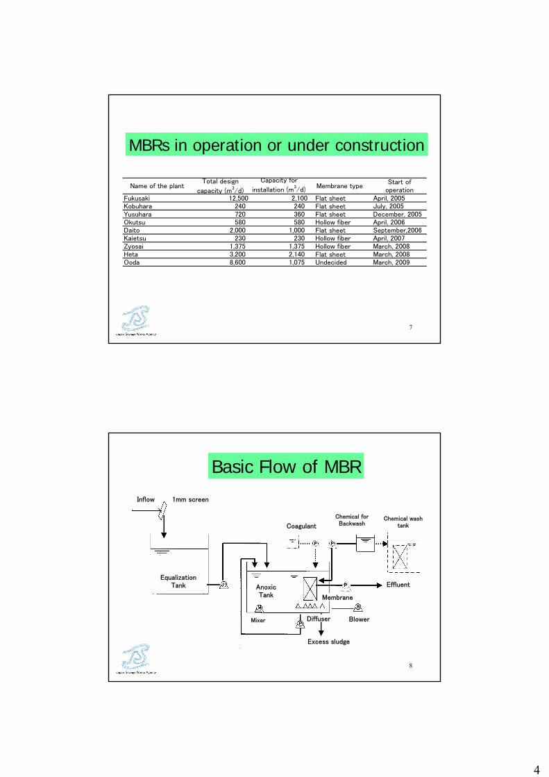
MBRs in operation or under construction
Fukusaki 12,500 2,100 Flat sheet April, 2005Kobuhara 240 240 Flat sheet July, 2005Yusuhara 720 360 Flat sheet December, 2005Okutsu 580 580 Hollow fiber April, 2006Daito 2,000 1,000 Flat sheet September,2006Kaietsu 230 230 Hollow fiber April, 2007Zyosai 1,375 1,375 Hollow fiber March, 2008Heta 3,200 2,140 Flat sheet March, 2008Ooda 8,600 1,075 Undecided March, 2009
Start ofoperation
Name of the plantTotal design
capacity (m3/d)
Capacity for
installation (m3/d)
Membrane type
8
1mm screenInflow
EqualizationTank
Mixer Diffuser
AnoxicTank
Excess sludge
Blower
Coagulant
Chemical forBackwash
Effluent
Membrane
Chemical washtank
Basic Flow of MBR

5
9
Membrane modules (FS)
10
FS Membrane module for large-scale application
6
11
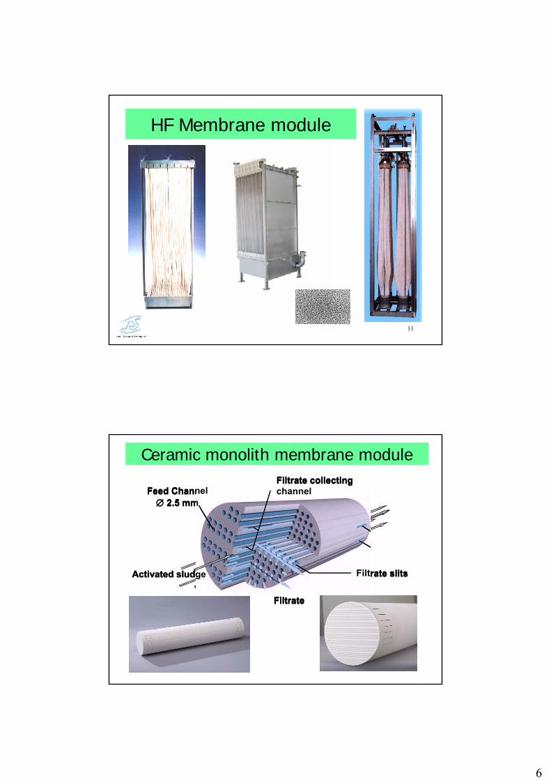
HF Membrane module
12
Filtrate
Filtrate collecting channel
Filtrate slits
Feed Channel∅ 2.5 mm
Ceramic monolith membrane module
Activated sludge
Filtrate
Filtrate collecting channel
Filtrate slits
Feed Channel∅ 2.5 mm
Activated sludge
7
13
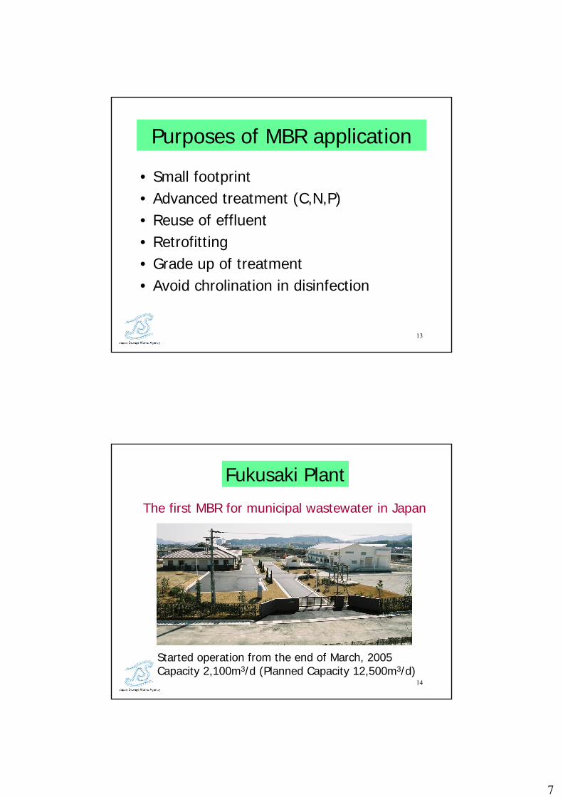
Purposes of MBR application
• Small footprint• Advanced treatment (C,N,P)• Reuse of effluent• Retrofitting• Grade up of treatment• Avoid chrolination in disinfection
14
Started operation from the end of March, 2005Capacity 2,100m3/d (Planned Capacity 12,500m3/d)
The first MBR for municipal wastewater in Japan
Fukusaki Plant
8
15
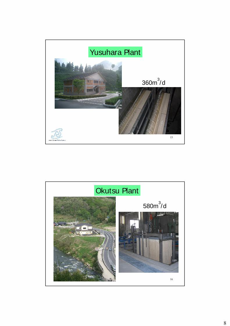
Yusuhara Plant
360m3/d
16
580m3/d
Okutsu Plant
9
17
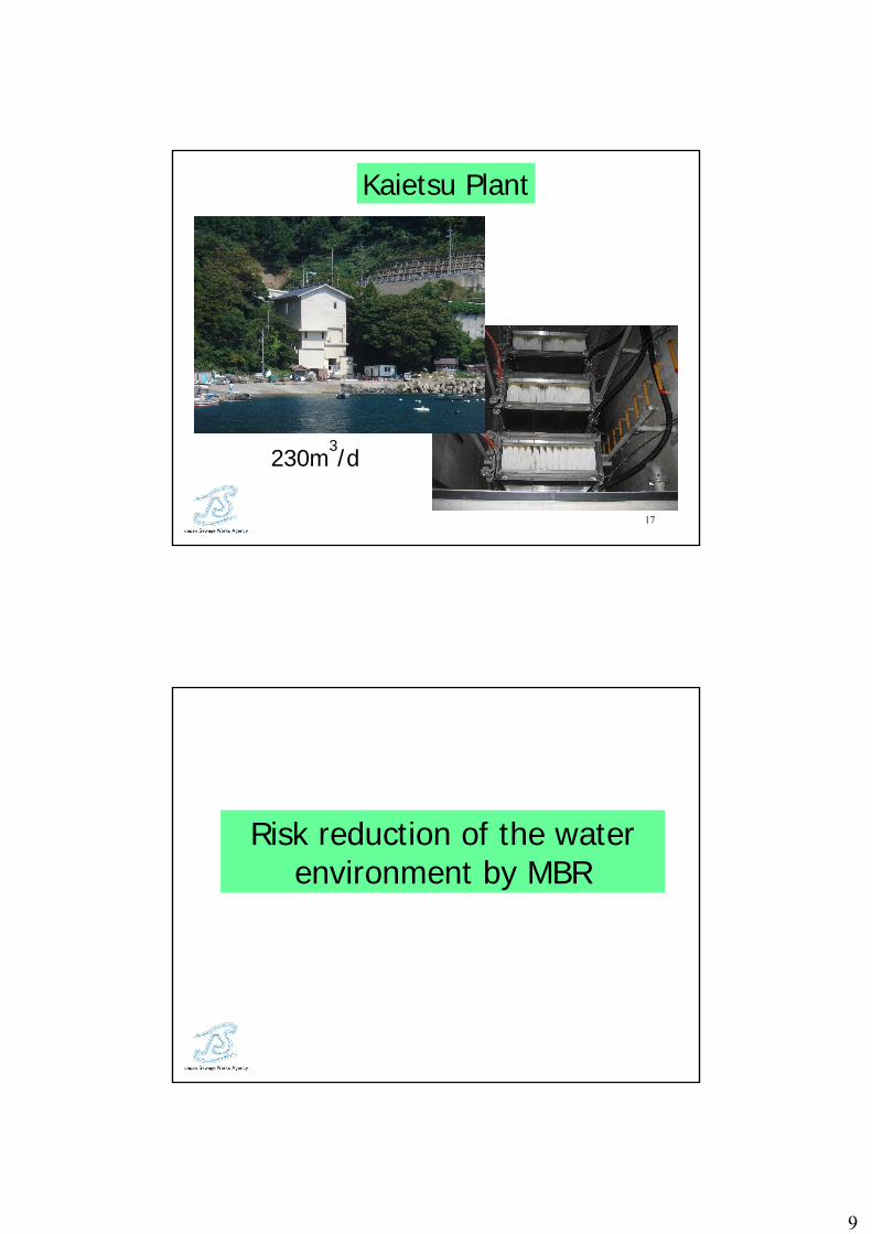
230m3/d
Kaietsu Plant
Risk reduction of the water environment by MBR

10
19
Φ25~35nm
Norovirus
Outbreak in this winter
Tolerant toward chlorine disinfectionVery small in the size
Main cause of food poisoning
From HP of Yokohama-city and Kyoto-city
20
Pilot plant
Capacity (m3/d) 48MLSS (g/L) 8-10Membrane module HFMaterial PVDFPore size (μm) 0.4
Flux (L/m2/hr) 33
TMP (kPa) <30
11
21
Experimental condition
Total HRT (hrs) Oxic HRT (hrs)Run-1 6 3Run-2 18 6Run-3 18 18
22
Oxic tank tank HRT(hrs)
Genome type GⅠ GⅡ GⅠ GⅡ GⅠ GⅡInfluent 4.20E+07 3.50E+08 2.50E+07 1.90E+08 2.50E+07 1.90E+08Aerobic tank sludge 1.10E+08 6.20E+07 1.50E+06 N.D. 2.70E+05 N.D.Effluent N.D. N.D. N.D. N.D. N.D. N.D.
(Copies/L)
3 6 18Run-1 Run-2 Run-3
Results of Norovirus mesurement

12
23
Φ25~35nm
Location of NorovirusSupernatant
Attached to solids
Attached to flocks → Rejection by membrane
24
Influence of in-line chemical cleaning
GⅠ GⅡ30min N.D. N.D.60min N.D. N.D.120min N.D. N.D.
(Copies/L)
Norovirus typeElapsed time afterchemical cleaning
13
25
• High removal efficiency by MF MBR• Adsorption of virus to sludge flocks is
the reason of removal• Gel layer on the membrane surface is
not important for virus removal
Summery of Norovirus removal
Application of MBR to BNR process
14
27
Effluent
A: anoxic tankO: oxic tankPDN: post-denitrification tankM: membrane
A O A O AEqualizing Tank O M
Methanol
PDN
Application of Membrane to Large-scale BNR Process
HRT 10hrs, T-Neff≦5mg/l
Pilot plant
28
20
40
60
80
100
0 2 6 8 10
Effluent T-N,Kj-N,NO -N mg/L
Cum
ula
tive
fre
quency
(%)
T-N KJ-N NO3-N
Nitrogen removal
15
29
0
0.5
1
1.5
2
2.5
3
3.5
4
4.5
5
A1 O2 A2 O2 A3 O3(M) PDN
N,P
(mg/
l)
NH4-N
NO3-N
PO4-P
Profiles in each tank
30

16
31
Perspective of future development of MBR
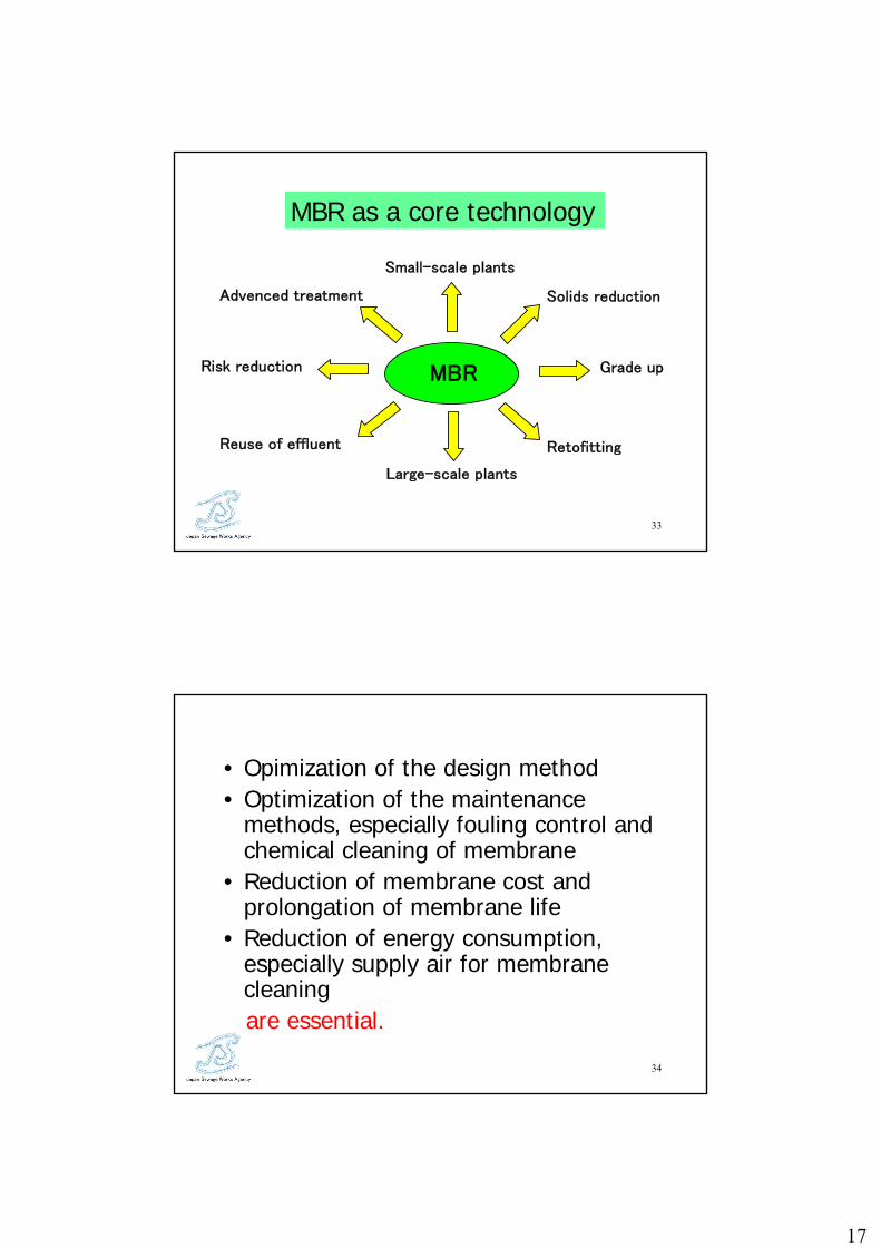
17
33
Advenced treatment
Small-scale plants
Retofitting
Grade upRisk reduction
Solids reduction
Large-scale plants
Reuse of effluent
MBR
MBR as a core technology
34
• Opimization of the design method• Optimization of the maintenance
methods, especially fouling control and chemical cleaning of membrane
• Reduction of membrane cost and prolongation of membrane life
• Reduction of energy consumption, especially supply air for membrane cleaningare essential.

18
Removal of EDCs by ozonation
36
• To reveal the efficiency and characteristics of estrogen decomposition by ozonation in treated wastewater.
Purpose of the study

19
37
15 minutes (fixed)Contact time
0.5, 1, 3, 5, 7, 10mg/LOzone dose
20, 200ng/LInitial concentration
17β-estradiol (E2)Estrone (E1)17α-ethynl estradiol (EE2)
Object substances
Ozonation experiment
38
Sampletank
Diffuser plate
Exhaustozone monitor
gaswater
Sampling valve
Exhaustgas
Air
Reactor tower
Generateozone
monitor
Activatedcarbon
adsorption
C
C
P
・ Effective depth : 1.8m・ Effective volume : 8.8L
Ozonizer
Experimental devices
20
39
0.1
1.0
10.0
100.0
1,000.0
0 2 4 6 8 10
ozone dose [mg/L]
E1・E2 [
ng/
L]
E2 E1
LOD
0.1
1.0
10.0
100.0
1,000.0
0 2 4 6 8 10
ozone dose [mg/L]
est
roge
nic
acti
vity
[ng-
E2/L]
estrogenic activity
LOD
(Initial estrogen concentration : E2, 200ng/L)
Changes of estrogen and estrogenic activity with ozone dose (1)
40
(Initial estrogen concentration : E1, 200ng/L)
0.1
1.0
10.0
100.0
1,000.0
0 2 4 6 8 10
ozone dose [mg/L]
E1・E2 [
ng/
L]
E2 E1
0.1
1.0
10.0
100.0
1,000.0
0 2 4 6 8 10
ozone dose [mg/L]
est
roge
nic
acti
vity
[ng-
E2/L]
estrogenic activity
LODLOD
Changes of estrogen and estrogenic activity with ozone dose (2)
21
41
(Initial estrogen concentration : EE2, 200ng/L)
0.1
1.0
10.0
100.0
1,000.0
0 2 4 6 8 10
ozone dose [mg/L]
E1・EE2 [
ng/
L]
E1 EE2
0.1
1.0
10.0
100.0
1,000.0
0 2 4 6 8 10
ozone dose [mg/L]
est
roge
nic
acti
vity
[ng-
E2/L]
estrogenic activity
LODLOD
Changes of estrogen and estrogenic activity with ozone dose (3)
42
OH
H3COH
A-Ring B-Ring
C-Ring D-Ring1
2
3
45
6
7
8
910
11
12
13
14 15
16
17The binding-site withthe estrogen receptor
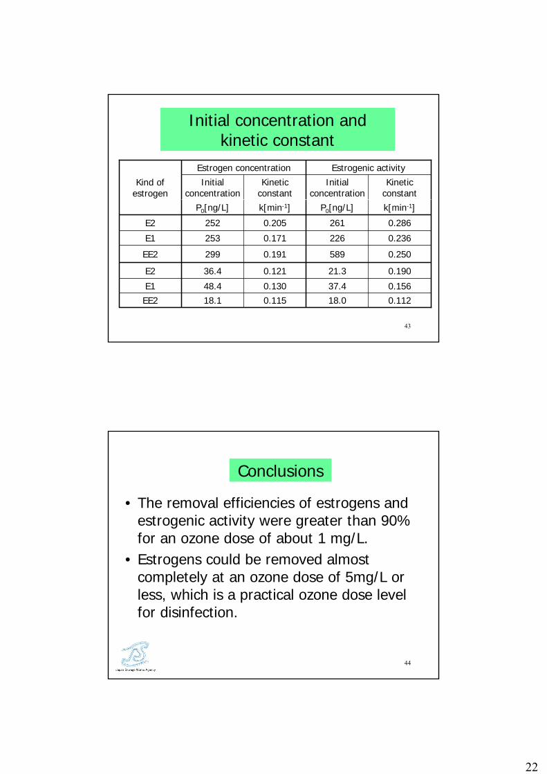
Chemical structure of E2
22
43
0.2862610.205252E2
0.11218.00.11518.1EE20.15637.40.13048.4E1
0.19021.30.12136.4E2
0.2505890.191299EE2
0.2362260.171253E1
k[min-1]P0[ng/L]k[min-1]P0[ng/L]
Kinetic constant
Initial concentration
Kinetic constant
Initial concentration
Estrogenic activityEstrogen concentration
Kind of estrogen
Initial concentration and kinetic constant
44
• The removal efficiencies of estrogens and estrogenic activity were greater than 90% for an ozone dose of about 1 mg/L.
• Estrogens could be removed almost completely at an ozone dose of 5mg/L or less, which is a practical ozone dose level for disinfection.
Conclusions

23
45
• No byproduct with estrogenic activity was produced during the decomposition process of estrogen by ozonation.
• The kinetic constant k was not much influenced by the type of estrogen.
Conclusions (continued)
New biological nitrogen removal method
-annamox process-
24
47
NH4+1.32NO2-+0.066HCO3
-+0.13H+→
1.02N2+0.26NO3-+0.066CH2O0.5N0.15+2.03H2O
annamox(anaerobic ammonium oxidation)
• Reduced oxygen requirement • External carbon source is not necessary• Small excess sludge production
48
Possible application of annamox process
Reduction of N load of sidestream from;• Anaerobic digester• Deodorization equipment of sludge drying
or composting process
A pilot-scale experiment starts soon.

25
49
Thank you for your kind attention!