new hearth lining direction at salzgitter flachstahl blast ... · pdf filenew hearth lining...
TRANSCRIPT

1
Abstract
In May 2004, Salzgitter Flachstahl in Germany rebuilt blast furnace B. This is a modern
furnace with a hearth diameter of 11.2m and a working volume of 2 530m3. This paper
describes one of the major changes that was made, namely to replace the existing
conventional carbon block hearth lining with a so called freeze lining made in USA. The
ambition is to accomplish a very long and trouble- free campaign, similar to what is recorded
at many other leading iron makers utilizing this concept and unique materials.
A general presentation is made of the three operating blast furnaces in Salzgitter; A, B and C.
This is followed by more detailed information concerning furnace B. The refractory lining
concept and materials installed are described. The excavation of the remains of the old lining
and the installation of the new lining were documented with numerous photographs of which
some of the most interesting are part of this paper. A high number of double thermocouples
were installed at different furnace elevations in the refractory hearth wall and bottom. Their
locations are shown together with the temperature readings for the first six months of
operation. The results are very convincing and promising for the future, showing very low,
stable and consistent temperatures at all critical sections of blast furnace B.
New Hearth Lining Direction at Salzgitter Flachstahl Blast Furnace B Dr.-ing. Jürgen Pethke, Salzgitter Flachstahl, Germany Dr.-ing. Tatjana Stišović, Salzgitter Flachstahl, Germany
Dipl.-ing. Peter Sylvén, Graftech International Ltd, USA

2
Fig. 1: The Salzgitter blast furnaces
Ladies and Gentlemen,
Before I start my presentation about our relining of furnace B, I would like to give you a short
overview of our other two blast furnaces A and C.
Blast furnace A was constructed in 1977. The last relining was in 1991 and the last
intermediate repair was made in 1996. The main reason for that repair was to install a new
supervising system similar to the one used for furnace B and to gun the upper shaft. The stop
was only 4 weeks.
Since 1977 this furnace uses copper plates from the tuyere level to the top for cooling the
shell. The hearth is spray cooled. In addition, the belly and the lower shaft area also have so
called mini-staves between the plates to protect the shell against the heat. This cooling system
is very efficient.
The next relining of this furnace will start in July this year after a production of 25 Mio. t HM.
The main objectives at this rebuild will be;
to increase the hearth diameter to the same dimension as furnace B,
to change the hearth spray cooling system to double jacket cooling
to renew the supervising system
to maintain the scrubber
to change the PW gear box
and several smaller repairs
Blast furnace C is both our oldest and our newest blast furnace. This furnace was first blown-
in 1940 and the last complete relining was in 1987. The furnace was then in operation for
about 5 years. Since then, we had to decide whether to reline the older furnaces 1, 2 and 5 or
to erect a new blast furnace. You already know the result of that discussions why we will talk
today about the relining of furnace B.
In Salzgitter in 2001, we discussed how to increase the steel production. The two suggested
possibilities were;
1. to increase the productivity of furnace A and B or
2. to restart a smaller furnace

3
As you are well aware, high productivity is expensive, especially better raw materials and
different tapping technique. So the decision was made to bring the old furnace C back in
operation. This solution was not cheap, but it was less expensive, from our point of view, than
the higher productivity option.
In blast furnace C we installed
a new bell less top from Paul Wurth
a new electric system from Electro Technologie in Gelsenkirchen
a new casthouse dedusting system
a new feeder to the furnace top (I think this might be the first vertical feeder to the top of a blast furnace)
a new pool runner in the casthouse
a new topgas cleaning system
13,4 MT of Hot-Pressed™ NMA bricks to refractory repair of the taphole areas
and some additional modifications
The furnace was blown-in in November 2004 and today the productivity results are as
expected.
Blast furnace B
But, Ladies and Gentlemen, let us now concentrate on blast furnace B.
Fig 2: Blast furnace B
This blast furnace was built in 1993 on a green field and its hearth diameter is 11,2 m, with a
working volume of 2 530 m3. The production rate in 2004 was 5 500 ton/day at an oil rate of
85 kg/thm. Design capacity for this furnace is 6 000 t/day and it is equipped with two tap
holes at an 84 degree angle in one cast house. Additional data is available in fig. 2. The
furnace is operated for 2 weeks with one taphole after which we change over and use the other
taphole for the same period.
4
The taphole clay used is resin bonded and soaking bar technique is used for about 80% of the
taps. Taphole length averages 2.5 m and the tap-to-tap time at both furnaces A and B is 40 to
50 min.
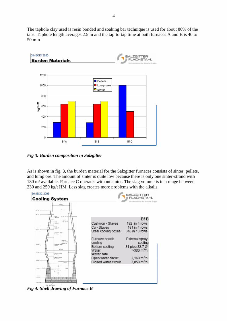
Fig 3: Burden composition in Salzgitter
As is shown in fig. 3, the burden material for the Salzgitter furnaces consists of sinter, pellets,
and lump ore. The amount of sinter is quite low because there is only one sinter-strand with
180 m² available. Furnace C operates without sinter. The slag volume is in a range between
230 and 250 kg/t HM. Less slag creates more problems with the alkalis.
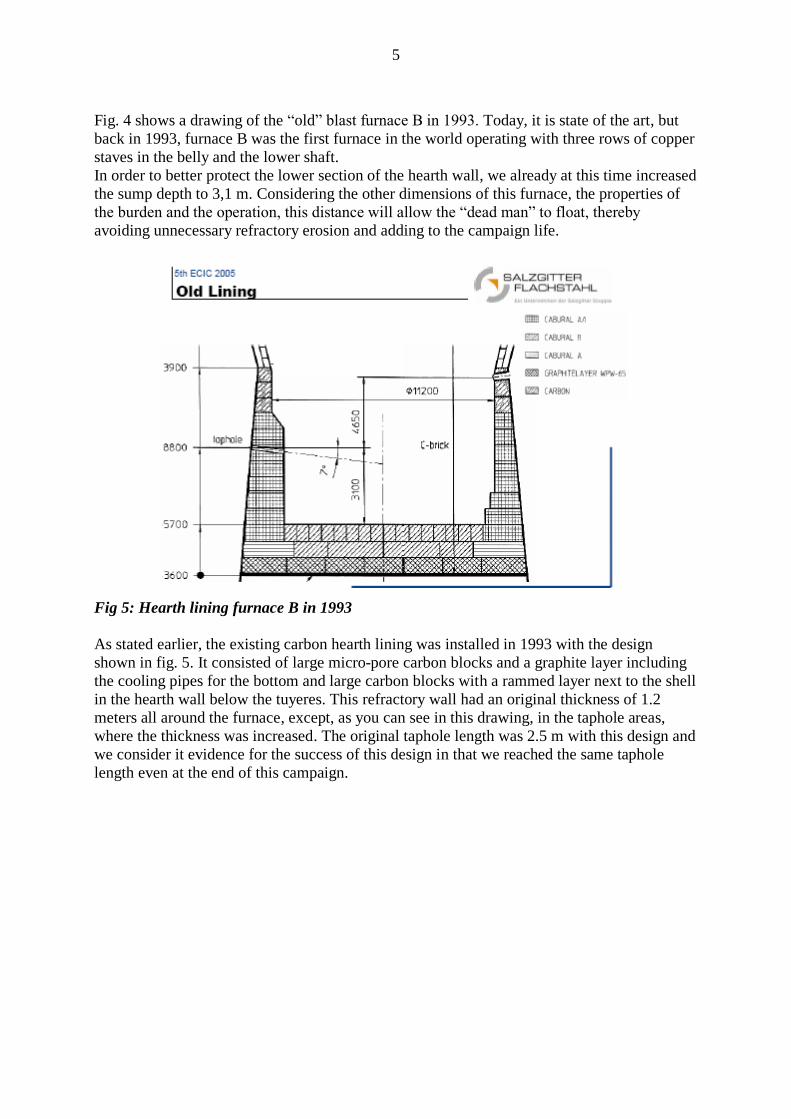
Fig 4: Shell drawing of Furnace B
5
Fig. 4 shows a drawing of the “old” blast furnace B in 1993. Today, it is state of the art, but
back in 1993, furnace B was the first furnace in the world operating with three rows of copper
staves in the belly and the lower shaft.
In order to better protect the lower section of the hearth wall, we already at this time increased
the sump depth to 3,1 m. Considering the other dimensions of this furnace, the properties of
the burden and the operation, this distance will allow the “dead man” to float, thereby
avoiding unnecessary refractory erosion and adding to the campaign life.
Fig 5: Hearth lining furnace B in 1993
As stated earlier, the existing carbon hearth lining was installed in 1993 with the design
shown in fig. 5. It consisted of large micro-pore carbon blocks and a graphite layer including
the cooling pipes for the bottom and large carbon blocks with a rammed layer next to the shell
in the hearth wall below the tuyeres. This refractory wall had an original thickness of 1.2
meters all around the furnace, except, as you can see in this drawing, in the taphole areas,
where the thickness was increased. The original taphole length was 2.5 m with this design and
we consider it evidence for the success of this design in that we reached the same taphole
length even at the end of this campaign.
6
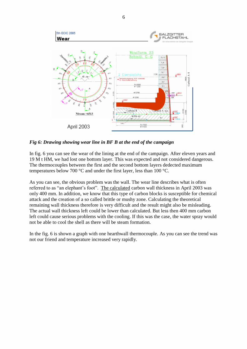
Fig 6: Drawing showing wear line in BF B at the end of the campaign
In fig. 6 you can see the wear of the lining at the end of the campaign. After eleven years and
19 M t HM, we had lost one bottom layer. This was expected and not considered dangerous.
The thermocouples between the first and the second bottom layers dedected maximum
temperatures below 700 °C and under the first layer, less than 100 °C.
As you can see, the obvious problem was the wall. The wear line describes what is often
referred to as “an elephant’s foot”. The calculated carbon wall thickness in April 2003 was
only 400 mm. In addition, we know that this type of carbon blocks is susceptible for chemical
attack and the creation of a so called brittle or mushy zone. Calculating the theoretical
remaining wall thickness therefore is very difficult and the result might also be misleading.
The actual wall thickness left could be lower than calculated. But less then 400 mm carbon
left could cause serious problems with the cooling. If this was the case, the water spray would
not be able to cool the shell as there will be steam formation.
In the fig. 6 is shown a graph with one hearthwall thermocouple. As you can see the trend was
not our friend and temperature increased very rapidly.
7
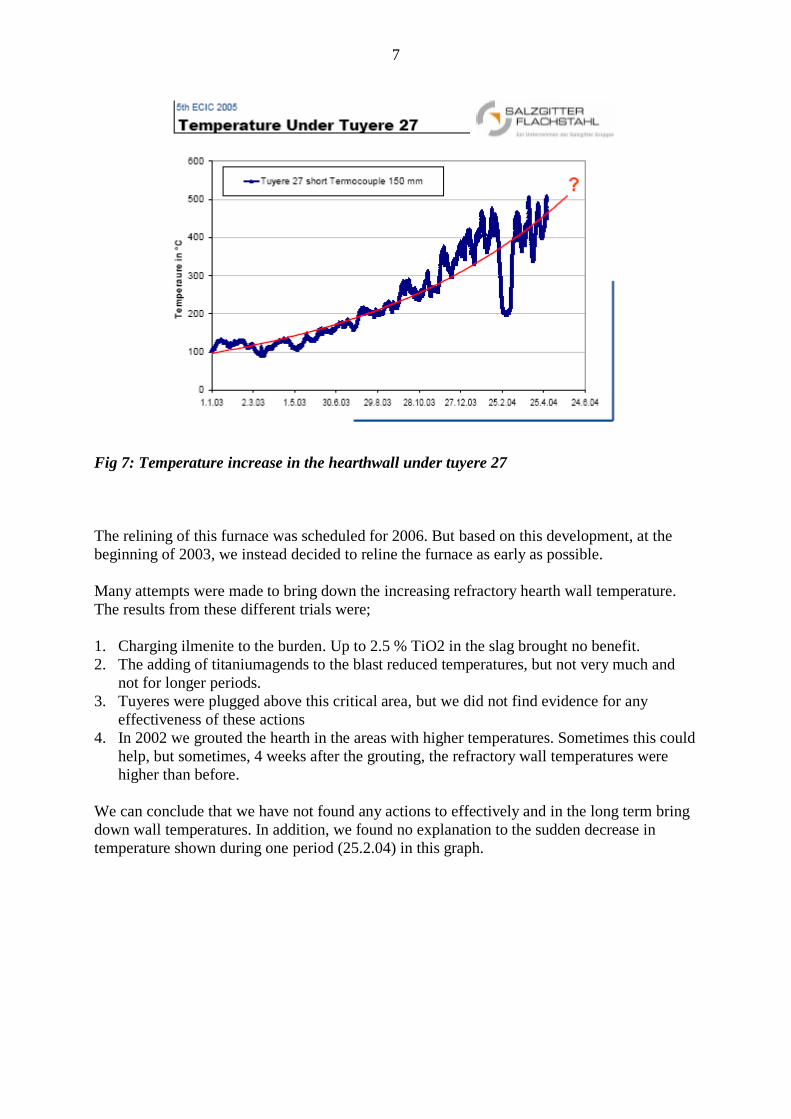
Fig 7: Temperature increase in the hearthwall under tuyere 27
The relining of this furnace was scheduled for 2006. But based on this development, at the
beginning of 2003, we instead decided to reline the furnace as early as possible.
Many attempts were made to bring down the increasing refractory hearth wall temperature.
The results from these different trials were;
1. Charging ilmenite to the burden. Up to 2.5 % TiO2 in the slag brought no benefit.
2. The adding of titaniumagends to the blast reduced temperatures, but not very much and
not for longer periods.
3. Tuyeres were plugged above this critical area, but we did not find evidence for any
effectiveness of these actions
4. In 2002 we grouted the hearth in the areas with higher temperatures. Sometimes this could
help, but sometimes, 4 weeks after the grouting, the refractory wall temperatures were
higher than before.
We can conclude that we have not found any actions to effectively and in the long term bring
down wall temperatures. In addition, we found no explanation to the sudden decrease in
temperature shown during one period (25.2.04) in this graph.

8
Fig 8: Photographs from the excavation of BF B June 2004
Before we continue to describe the new lining, I would like to show you some photos from
the excavation of the 11 year old carbon block lining. As you can see, the hearth wall
thickness was only 50 mm under tuyere 27. We can conclude that the calculation indicating a
400 mm wall thickness was wrong. The reason for this is also shown in this photograph.
There was a brittle or mushy zone found inside the carbon wall. The decision to stop this
furnace and do the relining was definitely correct.
The new hearth lining direction
Fig 9: Freeze lining concept for the blast furnace hearth.
9
The carbon refractory concept installed in blast furnace B in the summer of 2004 was a
change in the refractory hearth lining philosophy for Salzgitter. It is based on using a thin,
high thermal conductivity hearth wall and bottom with a geometric configuration that
provides long and trouble free campaigns. Let us take a closer look at this concept and the
materials used.
The Hearth Bottom
The hearth pad configuration shown in fig. 9 will establish a thermal equilibrium high up in
the pad. To achieve this cooling capacity requires a cooling course zone of very high thermal
conductivity graphite (150-160 WmK). In the case of the Salzgitter B furnace, the lower part
of the bottom pad was in good condition and was not replaced. On top of the existing graphite
and carbon bottom, two layers of super long carbon blocks were installed, each layer with a
thickness of 750 mm using blocks 4572 mm long. Long blocks mean fewer joints to control,
less pieces to handle and faster installation. These blocks have an intermediate thermal
conductivity and a low elastic modulus. On top of the long carbon blocks, we decided to use
200 mm of Olivine. The reason for this is primarily to facilitate initial electrical calibrations
and measurements and secondly, to protect the carbon bottom.
A ring of NMA Hot- Pressed™ carbon bricks surrounds the carbon block courses in the
bottom, serving several purposes. First, the brick ring against the shell moves the ram away
from the shell and the cooling, allowing it to bake and thereby improving a high and
consistent conductivity. Secondly, in the very unlikely event that iron penetrates to that point,
the NMA will act as a safety barrier against the shell, instead of depending on the ramming as
the final prevention against breakout. These bricks were cut to make tight contact with the
shell.
The ram between the carbon block courses and the NMA ring wall is RP-20 Smartram®. RP-
20 contains a specially treated form of graphite that expands up to three times its original
volume when heated, while exerting only small pressure on the surrounding structure.
Another unique feature is that the thermal conductivity for RP-20 increases with increased
temperature. This material ensures good thermal contact between the carbon block courses
and the NMA ring wall.
The Hearth Side Wall
This concept and US-made materials have been successfully used in hundreds of installations
around the world but only recently has it been used by European iron makers and now for the
first time in a full hearth lining in Germany. The concept using a very thin wall with many
cemented joints is very different to the traditional concept using thick walls, large blocks and
ram, supplied by local manufacturers, which could explain the resistance to converting.
The wall lining for BF B is only 0,9 m thick with a 1,8 m abutment at the tap holes and it is
designed to keep the entire lining thickness well below a temperature of 800 degrees C. This
wall is thinner than a conventional block lining, which reduces the resistance to heat transfer
and lowers the hot face temperature.

10
Fig 10: Drawing of new lining with TC design and TC locations
To control the wall temperatures, a high number of thermocouples (TC) were installed in 6
vertical lines with 8 double thermocouples each. Configuration and design are shown in fig.10
and as you can see several TC’s are also located in the hearth bottom.
The graphs in fig. 11 show you the TC readings at two different critical locations and at
depths of 100 and 200 mm inside the refractory wall for the first 6 months after start-up. And
as you can see, they are all very low and stable. As predicted, the hot face temperature is
maintained below the freezing point of the process and thus a protective layer, a skull, freezes
on the surface. This prevents erosion and insulates the lining thermally.
Fig11: Refractory temperatures at 100 and 200 mm inside the shell
11
In addition, the wall is constructed with small Hot-Pressed™ bricks instead of large blocks.
Segmenting the wall into multiple rings allows the hot face to expand independently from the
cold face, greatly reducing the internal stress that can cause cracks, impede heat transfer and
increase temperatures. Small pieces also have a smaller individual expansion that can easily
be absorbed by the cement joints, again preventing stress. Besides absorbing expansion, the
carbonaceous cement used also thermally connects bricks together, mechanically bonds them
and carbonises to fill the joints and prevent penetration.
Making the wall 1,8 m thick at the taphole area helps maintaining the desired taphole length.
However, the thicker wall is more difficult to cool properly unless steps are taken to reduce
the total thermal resistance. For this reason, a combination of NMA bricks (18 WmK) and
semi graphite Hot-Pressed™ bricks NMD (60 WmK) was used. Thus, the wall thickness is
1,8 m at the Salzgitter furnace B tap hole, but its thermal resistance is similar to that of the
rest of the 0,9 m wall.
The higher conductivity NMD bricks are also used in the centre part of the taphole; the
material draws additional heat from the surrounding sidewalls and concentrates it to the cold
taphole clay. This system stabilises casting, reduces clay consumption and enables earlier
casting/ better liquid control. The tap hole was core drilled from the outside of the furnace
after the wall was built, saving even further on installation time.
On the inside of the carbon brick wall was applied about 100 mm of ceramic bricks as start-up
protection.
Installation
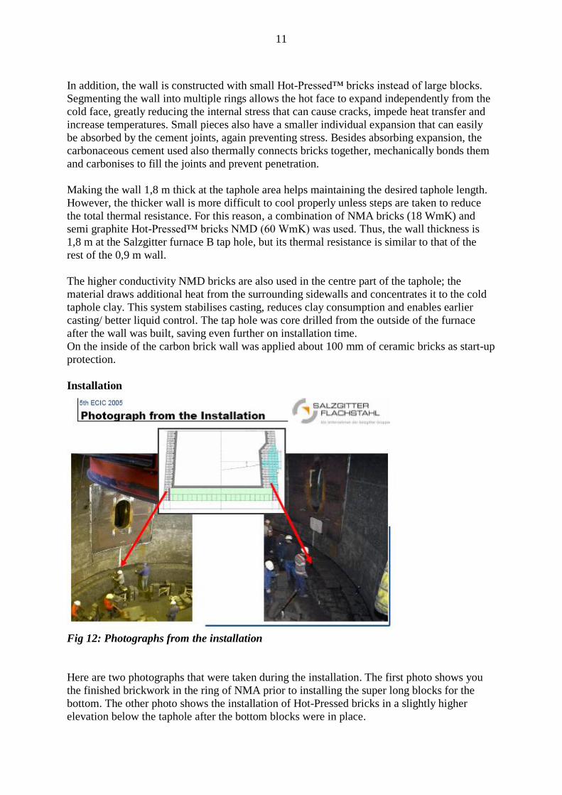
Fig 12: Photographs from the installation
Here are two photographs that were taken during the installation. The first photo shows you
the finished brickwork in the ring of NMA prior to installing the super long blocks for the
bottom. The other photo shows the installation of Hot-Pressed bricks in a slightly higher
elevation below the taphole after the bottom blocks were in place.

12
During the 30 day shut down of the furnace, the actual installation of the hearth bottom and
wall took 14 days, using two shifts, 11 hours each, for the bottom blocks; 11 brick layers and
9 labourers, for the walls 18 bricklayers and 17 labourers. The total amount of carbon material
installed in the hearth of blast furnace B during 2 weeks in June was about 900 metric tons.
Fig 13: Increase of hot metal production after blow- in
After the installing the Refractories described, the furnace was dried with hot blast for 12
hours after which the furnace was filled in the lower part with coke and in the upper part with
coke and slag components. The furnace was blown-in with all the tuyeres open and as you see
in fig. 13, a productivity exceeding 5000 t was reached already after 4 days. When the silicon
level had reached normal values, ilmenite was added for 17 days to build up an initial and
stable skull protection of the hearth wall.
Today, the refractory lining in blast furnace B is not a concern for the iron production. At
these early days of the campaign, we conclude that the lining behaves similar to that of the big
block design used in the previous campaign. The future will tell us how the performance
compares 11 years from now…
One problem that occurred after the blow-in, concerned the surface of the taphole area. The
concrete which was used in the previous campaign with a good result, now had a life reduced
to 4 weeks. The solution to this problem was to change to a CO and alkaline resistant castable.
In addition, we are making trials developing a taphole clay with less volatiles to improve the
liquid control.

13
Conclusion:
Salzgitter Flachstahl operates three modern blast furnaces and is always looking to improve
on technical parameters in the production. Continuous enhancement is key for long term
profitability. The ambition when selecting a thin so-called freeze refractory lining for the
hearth when rebuilding blast furnace B in the summer of 2004, was to accomplish a 15 year or
longer, trouble-free campaign. This paper shows that, so far, this looks very promising indeed
and strongly indicates that the appropriate design decisions were made.