new developments and special experiences in geoinform’s well testing ... · pdf filenew...
TRANSCRIPT

New Developments and Special Experiences in Geoinform’s Well
Testing Services
Peter Baranyi
Chief Engineer, GEOINFORM Ltd.
SEE Upstream 2015, Bucharest, 22-23 April

SEE Upstream 2015, Bucharest, 22-23 April
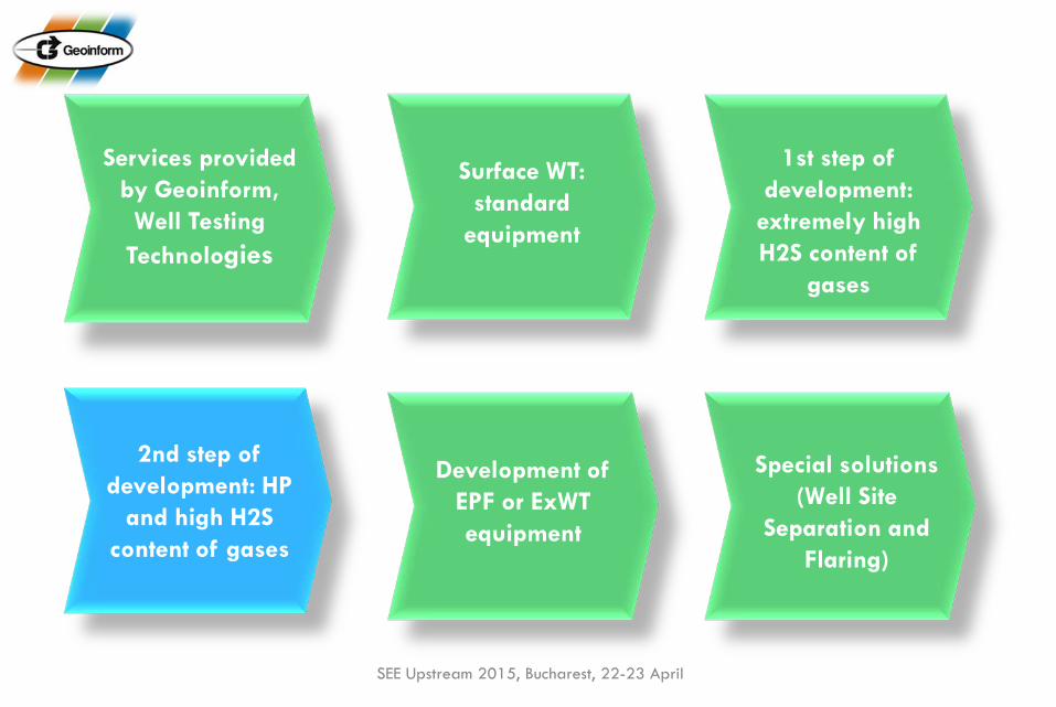
Services provided by Geoinform, Well Testing
Technologies
Surface WT: standard
equipment
1st step of development:
extremely high H2S content of
gases
2nd step of development: HP
and high H2S content of gases
Development of EPF or ExWT equipment
Special solutions (Well Site
Separation and Flaring)

A Brief Summary of Geoinform Services
SEE Upstream 2015, Bucharest, 22-23 April
Seismic Data Processing
OH and CH Wireline Services
(Logging & Perforation)
Slickline Services
Well Testing
Mud Logging
VSP
ISO 9001 Certified, ISO 14001 and OHSAS 1801 under certification

International Coverage
SEE Upstream 2015, Bucharest, 22-23 April

International Coverage (WT Services)
SEE Upstream 2015, Bucharest, 22-23 April
WT Base (Algyő)

Meaning of Well Testing • We attempt to answer questions such as Does this zone produce oil or gas? How much? What type? For how long will the well produce and at what pressure? Is it worth spending more and more money on the well to
increase the production?
• Well Test data and information are essential for experts working in exploration and production technology, as well as for reservoir engineers working with the reservoir.
• The subject of this presentation is the last year development of
our surface well testing service’s equipment and our experiences in a remote operation where the H2S and CO2 content of the produced gas was extremely high: 40% and 20% respectively SEE Upstream 2015, Bucharest, 22-23 April
Our Well Test Technologies • Downhole pressure and temperature survey
• SURFACE WELL TESTING
• EARLY PRODUCTION AND EXTENDED WELL TEST
• Sampling operations
• Echo- and dynamo-metering
• Sand monitoring (solid content determination)
• Installation of permanent pressure and temperature measuring systems
• Evaluation and interpretation of measured data
• Drill Stem Test (DST)
SEE Upstream 2015, Bucharest, 22-23 April

SEE Upstream 2015, Bucharest, 22-23 April
Services provided by Geoinform, Well Testing
Technologies
Surface WT: standard
equipment
1st step of development:
extremely high H2S content of
gases
2nd step of development: HP
and high H2S content of gases
Development of EPF or ExWT equipment
Special solutions (Well Site
Separation and Flaring)

Standard Surface Well Test Equipment
• Flow Head • Emergency Shut-Down (ESD)
system • High pressure pipelines and
data header • Choke manifold • Indirect-fired Heater • Test separators w/Surface data
acquisition system
SEE Upstream 2015, Bucharest, 22-23 April
• Low pressure pipeline system • Oil and gas manifold • Surge tank • Gauge tank • Flare system • Lab container • Accessories (Power supply,
lighting system, compressors, generators, chemical and transfer pumps)

Flow Head
SEE Upstream 2015, Bucharest, 22-23 April
• 4-valve configuration.; master-, wing-, swab-valves. One of the wing valve is hydraulic operated
• Size; 3 1/16”; WP; 10K, • Max Lifting Load;
400,000lbs (180tons). It should be able to support the full string weight.
• Swivel; allows rotation of the string w/o rotating the FH
• Sour gas service!

Emergency Shut-Down (ESD) System
SEE Upstream 2015, Bucharest, 22-23 April
• ESD (Emergency Shut Down) System is used for automatic closing of gate valves on wellheads and flow lines under emergency conditions
• Equipment; hydraulic actuator & revers acting gate valve; Solenoid valve, Pressure pilots and transducers, controlling panel (PLC), shut-down buttons

Piping • Up and Downstream piping; High and low
pressure pup joints (w/heated jacket), elbows, Xovers, adapters…etc.
• Data header: into which pressure and temperature measuring gauges can be inserted; they are also suitable for sampling and chemical injecting operations.
• Weco connections (Fig 1502, 206);
SEE Upstream 2015, Bucharest, 22-23 April
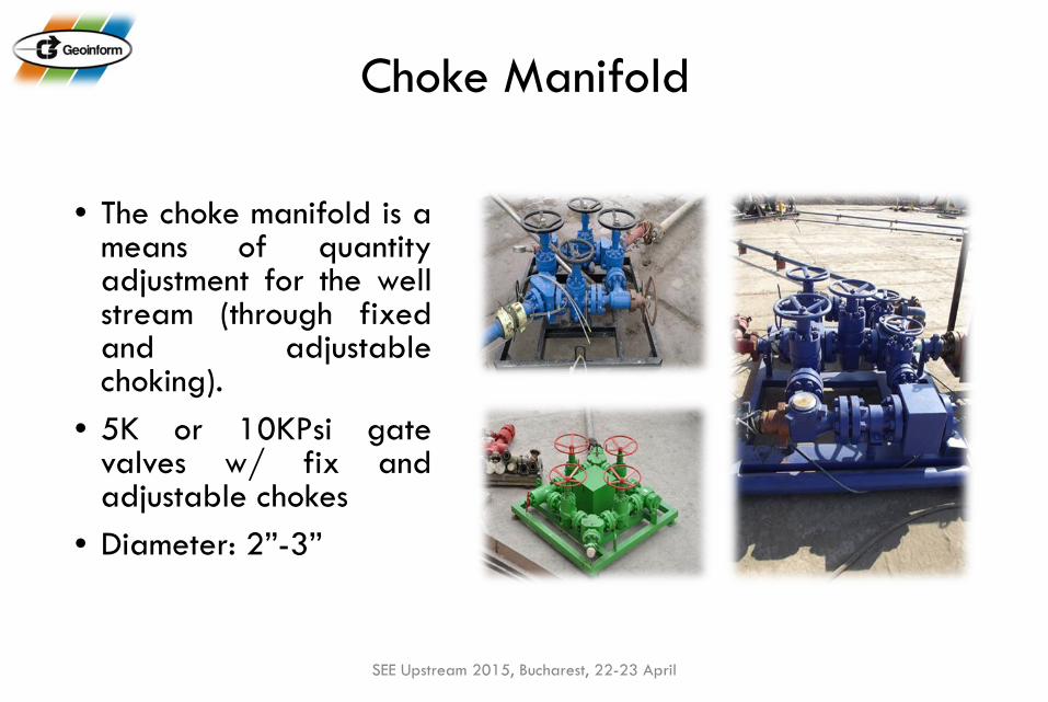
Choke Manifold
• The choke manifold is a means of quantity adjustment for the well stream (through fixed and adjustable choking).
• 5K or 10KPsi gate valves w/ fix and adjustable chokes
• Diameter: 2”-3”
SEE Upstream 2015, Bucharest, 22-23 April

Indirect-fired Heater and Boiler Units • 3”/5KPsi piping inside w/
adjustable choke • Vessel for water bath at
atmospheric pressure • Diesel and/or gas burner • External circulation pump • Heating capacity: 2 MMBtu/hr
• Hot water; 95degC • Heating capacity; 450KW • Circulation pump; Grundfos • Pmax; 2bar • Diesel burner
SEE Upstream 2015, Bucharest, 22-23 April

Test Separator (3 phase/100bar)
SEE Upstream 2015, Bucharest, 22-23 April
Design principles: • Easy to operate • Automatic and manual control
(fail safe) • ESD valve at the inlet • Bypass lines (metering devices) • Separation of liquid phases: 2
rooms divided by the weir.
The oil sitting on top of water will pass over the top of the weir and goes into the oil compartment

Separator Controlling and Transducers • PLC based controlling and Data Acquisition system • Level-controlling system: 3 and 2 phase sensitive Guided Radar transducers, Fisher Dump
valve: manual and automatic driven (EP converter box). • Gas volume; Daniel orifice box and/or Vortex • Liquid volume; turbine meter • Adjustable choke; to set the pressure of the separator • Pressure and temperature transducers (4-20mA)
SEE Upstream 2015, Bucharest, 22-23 April

Surface Data Acquisition System
• The system is able to sample each data point at a minimum of 5 second intervals and allow monitoring in real time on site on a screen. It is possible to reproduce hard copies of data on site.
• Pressure sensors shall have an accuracy of 0.1% of full scale reading (differential pressure: 0.075% of full scale) and temperature sensors an accuracy of 0.5°C
• Separator pressure and temperature is recorded automatically
SEE Upstream 2015, Bucharest, 22-23 April

Oil and Gas Diverter Manifolds
• WP; 1440Psi (100bar)
• ND; 3” (oil) and 4” (gas)
• Sour gas service
SEE Upstream 2015, Bucharest, 22-23 April

Surge and Gauge Tank Surge Tank (pressurized) • to store liquid hydrocarbons after
separation • to measure liquid flow rates • to calibrate the separator metering
devices • WP; 16bar
Gauge Tank (atmospheric) • to store liquid hydrocarbons after
separation • to measure liquid flow rates • 2 section boxes • Dual compartment • Level metering manually checked • Sight glasses indicators
SEE Upstream 2015, Bucharest, 22-23 April

Lab container
SEE Upstream 2015, Bucharest, 22-23 April
• RANAREX Portable Gas gravimeter, Heated Centrifuge, Glass centrifuge tubes (10 ml), Liquid density meter, Multi Gas detector (H2S, CO, O2, N, etc…), H2S personal detector, Digital thermometer, Glass beaker set, Graduated Cylinder (1000 ml, plastic), Mercury manometer, Range of pressure gauges, thermometers
• PH test tape, Digital PH meter, Manual centrifuge, Centrifuge glass (10ml, 20pcs/set), Beaker set (different capacity (100ml - 750ml), Salinity (chloride) kit, Chemical inhibitors, demulsifier (emulsion breaker).

Burner and Flare system
SEE Upstream 2015, Bucharest, 22-23 April
3”x18ft, 4”x18ft , 6”x40ft

Accessories
• Power supply and lighting system
• Compressors • Generators • Office, crew, storage
containers • Chemical injection pumps • Transfer pump systems • Gauges, Well Head Recorders,
Black Chart Recorders… • Consumables
SEE Upstream 2015, Bucharest, 22-23 April

Typical layout
SEE Upstream 2015, Bucharest, 22-23 April

SEE Upstream 2015, Bucharest, 22-23 April
Services provided by Geoinform, Well Testing
Technologies
Surface WT: standard
equipment
1st step of development:
extremely high H2S content of
gases
2nd step of development: HP
and high H2S content of gases
Development of EPF or ExWT equipment
Special solutions (Well Site
Separation and Flaring)

Surface Well Test Advanced Package (extremely high H2S, Pmax=10K)
• Sample taking: use breathing apparatus, training, H2S alarm system
• Upstream piping: NO threaded connection and elastomers! Only steel-on-steel (flanged)! Coflexip hoses from the flowhead
• Heater: in the upstream!
• Gauge tank: NO! Only surge tank!
• Burner and Flare stack: as far as possible, tubing lines…
• Install 2 sets of burners, 3 air compressors (800scfm/each)
• 8”x60’ ft flare stack w/3x4” vent lines up • 150 joints of 3-1/2 PH-6 (BTS-6) to make up 3 more lines going to the main burn-
pit and flare stack area (5x300m!)
• Certified NACE “welded” piping for all HP gas and oil lines for downstream
• Weco union is ok for downstream of choke manifold. SEE Upstream 2015, Bucharest, 22-23 April

SEE Upstream 2015, Bucharest, 22-23 April
The Scope changed…

P&ID (extremely high H2S, Pmax=10K)
SEE Upstream 2015, Bucharest, 22-23 April

SEE Upstream 2015, Bucharest, 22-23 April
Rig up

SEE Upstream 2015, Bucharest, 22-23 April
Flare stack
SEE Upstream 2015, Bucharest, 22-23 April
Services provided by Geoinform, Well Testing
Technologies
Surface WT: standard
equipment
1st step of development:
extremely high H2S content of
gases
2nd step of development: HP
and high H2S content of gases
Development of EPF or ExWT equipment
Special solutions (Well Site
Separation and Flaring)

Surface Well Test Advanced Package (high H2S and CO2, Pmax=15K)
HP Upstream side (15KPsi)
Coflex hose (flanged) HP flange piping Choke Manifold
SEE Upstream 2015, Bucharest, 22-23 April
Downstream side 10K Heater, 3 phase/100bar Separator Welded LP pipes Surge tank (NO gauge tank) 60ft flare (four line) Two BURNER 3 AIR Compressor (+two spare) All vent line are connected to the flare
system 3x 500 m LP piping for the flare system Special Oil diverter
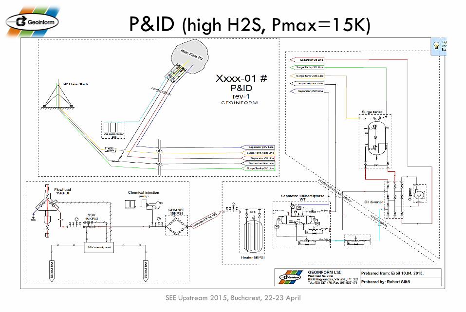
P&ID (high H2S, Pmax=15K)
SEE Upstream 2015, Bucharest, 22-23 April

Surface Equipment Layout (high H2S, Pmax=15K)
SEE Upstream 2015, Bucharest, 22-23 April

SEE Upstream 2015, Bucharest, 22-23 April
LP Piping, Compressors and the Burner
SEE Upstream 2015, Bucharest, 22-23 April
Services provided by Geoinform, Well Testing
Technologies
Surface WT: standard
equipment
1st step of development:
extremely high H2S content of
gases
2nd step of development: HP
and high H2S content of gases
Development of EPF or ExWT equipment
Special solutions (Well Site
Separation and Flaring)

Extended Well Test • A particular well is put into production as quickly as possible while the final surface
technology is completed, thereby improving return of the investment. Well Testing performed during the production and the data acquisition helps in designing the final technology, thereby minimizing the risks and the expense.
• EWT also provide a way to test sand control techniques and process- and production-related technologies. Such testing minimizes risks related to developing a field for long-term, sustained production.
SEE Upstream 2015, Bucharest, 22-23 April

Specific Extended Well Test System
• 2 pcs 10KPsi upstream manifolds • 1 ps upstream SKO • 1 pc upstream flow diverted • 1 pc 5KPsi downstream manifolds • 1 pcs 5Kpsi downstream ESD • 1 pc second separator (solid content) • Upstream side heated jackets • Downstream side 5KPsi heater • 2 pc 100m3 storage tank • 1 pc 50m3 storage tank • 1 pc 30m3 gauge tank • 1 pc 16m3 surge tank • 1 pc 20 m3 tank (for sand)
SEE Upstream 2015, Bucharest, 22-23 April

Equipment Layout (Ex. Well Test)
SEE Upstream 2015, Bucharest, 22-23 April

P&ID Extended Well Test
SEE Upstream 2015, Bucharest, 22-23 April

SEE Upstream 2015, Bucharest, 22-23 April

SEE Upstream 2015, Bucharest, 22-23 April
Services provided by Geoinform, Well Testing
Technologies
Surface WT: standard
equipment
1st step of development:
extremely high H2S content of
gases
2nd step of development: HP
and high H2S content of gases
Development of EPF or ExWT equipment
Special solutions (Well Site
Separation and Flaring)

Well Site Separation & Flaring Facility
Design: Total production volume: 8,500 bbl/day, Natural gas: 600 GOR • Oil production volume: 5,000 bbl/day – Crude Oil • Water production volume: 3,500 bbl/day – Formation Water
ESD + control panel, HP&LP piping, Choke manifold, gas and oil diverters 2pcs of indirect Heaters Production Separator (3 phase 16m3, WP 5bar, Knock Out Drum (10m3, 2 phase, function: to separate liquid from waste gases) Flare stack (large capacity 5.000 Nm3/h, ignition system, 60ft, 6”) Slop tanks (function: collection of drains form technology) Special recover, transfer, oil, pre-start pumps Surge tank (16m3, 16bar, magnetic level indicator)
SEE Upstream 2015, Bucharest, 22-23 April

Well Site Separator & Flaring Facility
SEE Upstream 2015, Bucharest, 22-23 April

SUMMARY
SEE Upstream 2015, Bucharest, 22-23 April
Lessons learned: • Safety at first! • Customers’ needs are always increasing. • Support the customer before, during and after the project. • Well Test has to be carried out even in harsh physical environment
(H2S, CO2, HP…) • Even the most advanced equipment could be operated by well
trained and committed people only. • Keep improving your technology. • Lead the development, maintain good relationship with your
suppliers. • Availability is important to maintain reputation and stay in the
business.
