networking embedded systems with xbee - florida gulf...
TRANSCRIPT

1
Networking Embedded Systems with
XBee
Romeo Sinjari, Julian Ryan, Sergio Pais
Draft No. 4
October 25, 2014
CNT 4104 Software Project in Computer Networks
Instructor: Dr. Janusz Zalewski
Software Engineering Program
Florida Gulf Coast University
Ft. Myers, FL 33965
2
1. Introduction
Remote monitoring and sensor networks serve an important role in commercial enterprise
but have been exclusive to niche business applications. Fortunately, low-cost wireless
communication modules and embedded systems have recently become available to everyone
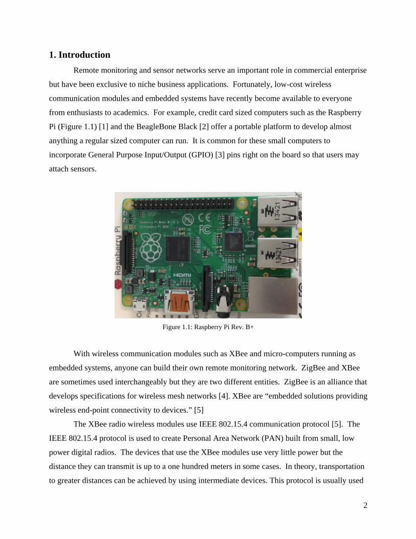
from enthusiasts to academics. For example, credit card sized computers such as the Raspberry
Pi (Figure 1.1) [1] and the BeagleBone Black [2] offer a portable platform to develop almost
anything a regular sized computer can run. It is common for these small computers to
incorporate General Purpose Input/Output (GPIO) [3] pins right on the board so that users may
attach sensors.
Figure 1.1: Raspberry Pi Rev. B+
With wireless communication modules such as XBee and micro-computers running as
embedded systems, anyone can build their own remote monitoring network. ZigBee and XBee
are sometimes used interchangeably but they are two different entities. ZigBee is an alliance that
develops specifications for wireless mesh networks [4]. XBee are “embedded solutions providing
wireless end-point connectivity to devices.” [5]
The XBee radio wireless modules use IEEE 802.15.4 communication protocol [5]. The
IEEE 802.15.4 protocol is used to create Personal Area Network (PAN) built from small, low
power digital radios. The devices that use the XBee modules use very little power but the
distance they can transmit is up to a one hundred meters in some cases. In theory, transportation
to greater distances can be achieved by using intermediate devices. This protocol is usually used
3
in low data rate applications that require long battery life and a secure network.
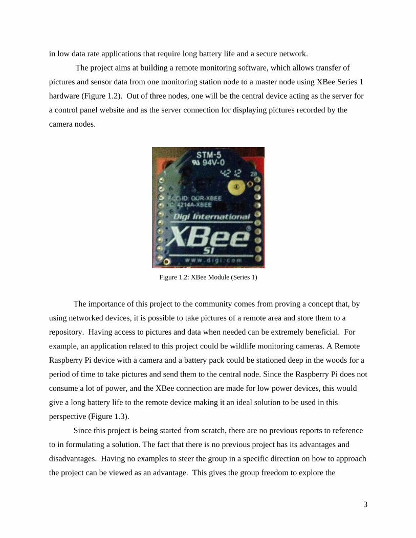
The project aims at building a remote monitoring software, which allows transfer of
pictures and sensor data from one monitoring station node to a master node using XBee Series 1
hardware (Figure 1.2). Out of three nodes, one will be the central device acting as the server for
a control panel website and as the server connection for displaying pictures recorded by the
camera nodes.
Figure 1.2: XBee Module (Series 1)
The importance of this project to the community comes from proving a concept that, by
using networked devices, it is possible to take pictures of a remote area and store them to a
repository. Having access to pictures and data when needed can be extremely beneficial. For
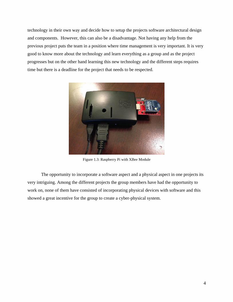
example, an application related to this project could be wildlife monitoring cameras. A Remote
Raspberry Pi device with a camera and a battery pack could be stationed deep in the woods for a
period of time to take pictures and send them to the central node. Since the Raspberry Pi does not
consume a lot of power, and the XBee connection are made for low power devices, this would
give a long battery life to the remote device making it an ideal solution to be used in this
perspective (Figure 1.3).
Since this project is being started from scratch, there are no previous reports to reference
to in formulating a solution. The fact that there is no previous project has its advantages and
disadvantages. Having no examples to steer the group in a specific direction on how to approach
the project can be viewed as an advantage. This gives the group freedom to explore the
4
technology in their own way and decide how to setup the projects software architectural design
and components. However, this can also be a disadvantage. Not having any help from the
previous project puts the team in a position where time management is very important. It is very
good to know more about the technology and learn everything as a group and as the project
progresses but on the other hand learning this new technology and the different steps requires
time but there is a deadline for the project that needs to be respected.
Figure 1.3: Raspberry Pi with XBee Module
The opportunity to incorporate a software aspect and a physical aspect in one projects its
very intriguing. Among the different projects the group members have had the opportunity to
work on, none of them have consisted of incorporating physical devices with software and this
showed a great incentive for the group to create a cyber-physical system.
5
2. Software Requirements Specification
The primary goal for the project is to have the Remote Raspberry Pi devices take pictures
using the attached camera and send it using the XBee wireless connectors to the Central
Raspberry Pi device. An additional objective is to host a web page, to be available on the local
area network. Pictures sent to the central Raspberry Pi are displayed on that web page.
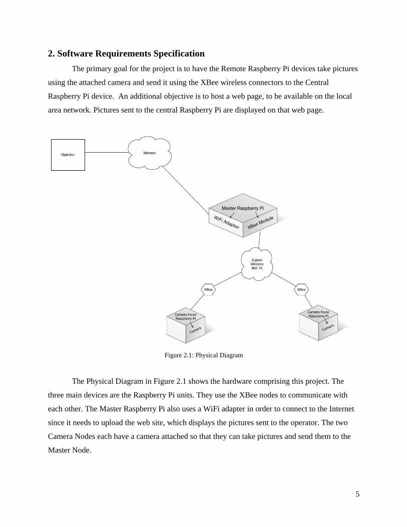
Figure 2.1: Physical Diagram
The Physical Diagram in Figure 2.1 shows the hardware comprising this project. The
three main devices are the Raspberry Pi units. They use the XBee nodes to communicate with
each other. The Master Raspberry Pi also uses a WiFi adapter in order to connect to the Internet
since it needs to upload the web site, which displays the pictures sent to the operator. The two
Camera Nodes each have a camera attached so that they can take pictures and send them to the
Master Node.
6
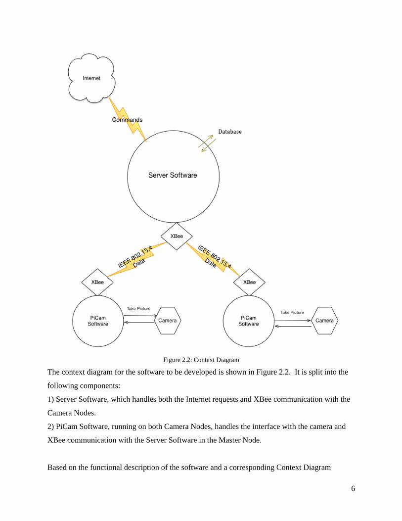
Figure 2.2: Context Diagram
The context diagram for the software to be developed is shown in Figure 2.2. It is split into the
following components:
1) Server Software, which handles both the Internet requests and XBee communication with the
Camera Nodes.
2) PiCam Software, running on both Camera Nodes, handles the interface with the camera and
XBee communication with the Server Software in the Master Node.
Based on the functional description of the software and a corresponding Context Diagram

7
(Figure 2.2) the following requirements have been developed separately for the Server Software
and PiCam Software.
Server Software Requirements:
S1) Upon the user entering the authentication information and pressing “Log In” the Server
Software shall compare the information entered with the information in the database, and if
valid, allows user access to Server Software commands.
S2) Upon the user entering the command “Take Picture”, the Server Software shall send the
command, via the XBee device, to both of the Camera Nodes PiCam Software to take a picture.
S3) Upon receiving the picture taken from the each of the Camera Nodes PiCam Software, the
Server Software shall save a reference to the picture in the database.
S4) Upon receiving the picture taken from the any of the Camera Nodes PiCam Software, the
Server Software shall host a respective image on the website.
PiCam Software Requirements:
C1) Upon receiving the “Take Picture” command from the Server Software the PiCam Software
shall make the Camera Node take a picture.
C2) Upon taking the picture the PiCam Software shall send the picture to the server via the
XBee device.
8
3. Design Description
3.1 Server Software Architecture
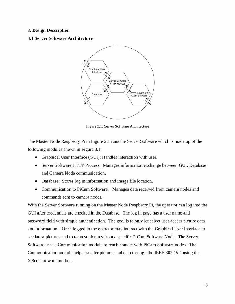
Figure 3.1: Server Software Architecture
The Master Node Raspberry Pi in Figure 2.1 runs the Server Software which is made up of the
following modules shown in Figure 3.1:
● Graphical User Interface (GUI): Handles interaction with user.
● Server Software HTTP Process: Manages information exchange between GUI, Database
and Camera Node communication.
● Database: Stores log in information and image file location.
● Communication to PiCam Software: Manages data received from camera nodes and
commands sent to camera nodes.
With the Server Software running on the Master Node Raspberry Pi, the operator can log into the
GUI after credentials are checked in the Database. The log in page has a user name and
password field with simple authentication. The goal is to only let select user access picture data
and information. Once logged in the operator may interact with the Graphical User Interface to
see latest pictures and to request pictures from a specific PiCam Software Node. The Server
Software uses a Communication module to reach contact with PiCam Software nodes. The
Communication module helps transfer pictures and data through the IEEE 802.15.4 using the
XBee hardware modules.
9
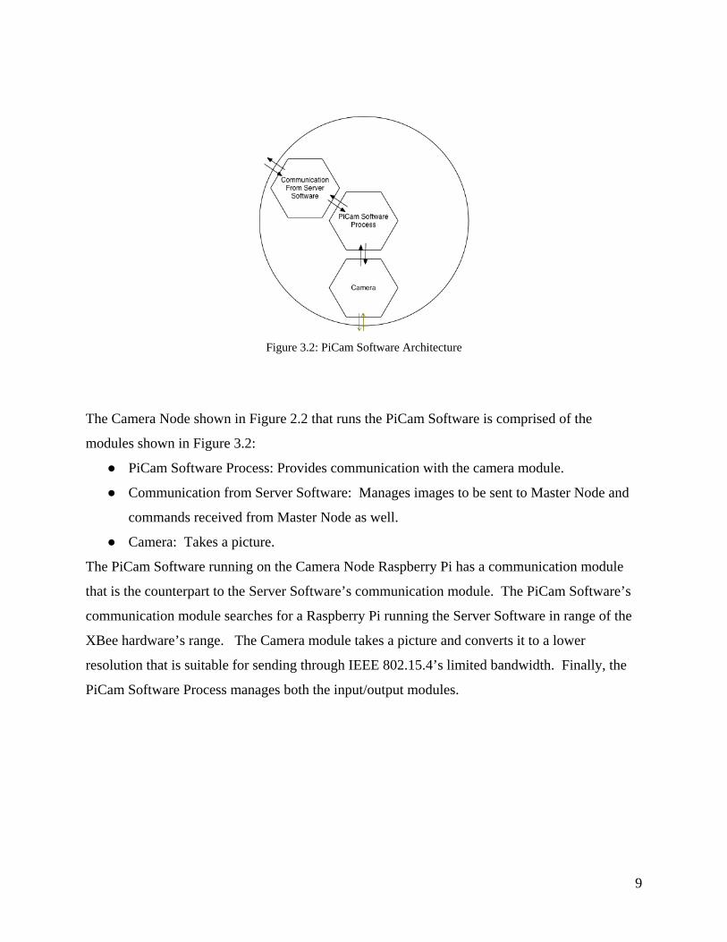
Figure 3.2: PiCam Software Architecture
The Camera Node shown in Figure 2.2 that runs the PiCam Software is comprised of the
modules shown in Figure 3.2:
● PiCam Software Process: Provides communication with the camera module.
● Communication from Server Software: Manages images to be sent to Master Node and
commands received from Master Node as well.
● Camera: Takes a picture.
The PiCam Software running on the Camera Node Raspberry Pi has a communication module
that is the counterpart to the Server Software’s communication module. The PiCam Software’s
communication module searches for a Raspberry Pi running the Server Software in range of the
XBee hardware’s range. The Camera module takes a picture and converts it to a lower
resolution that is suitable for sending through IEEE 802.15.4’s limited bandwidth. Finally, the
PiCam Software Process manages both the input/output modules.
10
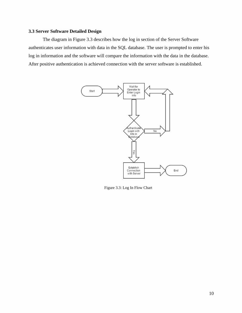
3.3 Server Software Detailed Design
The diagram in Figure 3.3 describes how the log in section of the Server Software
authenticates user information with data in the SQL database. The user is prompted to enter his
log in information and the software will compare the information with the data in the database.
After positive authentication is achieved connection with the server software is established.
Figure 3.3: Log In Flow Chart

11
The diagram in Figure 3.4 describes how the Server Software is getting connected to the
PiCam Software. After the server receives the “Take Picture” command from the user through
the website it will try to connect to the camera nodes through the XBee device. If the Server
Software cannot establish connection it will keep trying to connect until it does. Upon
establishing connection, the Server Software shall sent the Camera Node the command to take
the picture and the picture will be uploaded to the server by the PiCam software. In case there is
no picture uploaded the software will timeout after 2 minutes and send another request to the
PiCam Software for a picture.
Figure 3.4: Server Software to PiCam Software Communication Flow Chart

12
3.4 PiCam Software Detailed Design
The diagram in Figure 3.5 describes how the PiCam software runs on each Camera Node
Raspberry Pi. The PiCam Software initiates by pinging the Server Software to see if it is online.
If there is no known Server Software, the process will sleep for one minute until checking again.
Next, the PiCam Software will check for any existing commands received from the Server
Software. If there are no orders from the Server Software, the PiCam Software will wait until
there is one. Once there is a command to take a picture, the PiCam Software will take a picture
and attempt to send it to the Server Software.
Figure 3.5: PiCam Software Flow Chart
13
3.5 Graphical User Interface
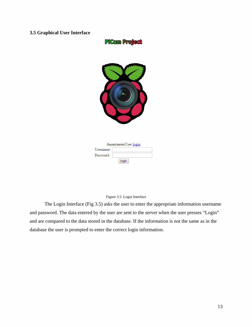
Figure 3.5: Login Interface
The Login Interface (Fig 3.5) asks the user to enter the appropriate information username
and password. The data entered by the user are sent to the server when the user presses “Login”
and are compared to the data stored in the database. If the information is not the same as in the
database the user is prompted to enter the correct login information.

14
Figure 3.6: PiCam Control Command Interface
The PiCam Control Command Interface (Fig 3.6) allows the user to send commands to
the Server Software. Based on the camera selection, individual commands can be sent to either
Camera 1, Camera 2 or both cameras simultaneously. The interface is designed to allow for
additional actions other than “Take Snapshot” to be implemented. On the left side of the web
page (in Fig 3.6), the displays for the two cameras can be seen. The image to be displayed is the
most recent picture received.

15
4. Implementation and Testing
The Server Software and the PiCam Software are implemented using Python but run
using different libraries and frameworks. The PiCam Software uses more low level libraries
included with a typical Python distribution. The Server Software uses a high level framework
called Django [6] that runs a HTTP server to display web pages. Figure 4.1 shows the PiCam
Software’s take picture function. The resolution of pictures that can be realistically sent through
the XBee module are limited to about 200 by 150 pixels. Images that are bigger in resolution
result in the XBee module’s timing out during transfer. Since the XBee transfer is timed out, the
image is partially sent and the resulted image is corrupted.
def takepicture(): with picamera.PiCamera() as camera: camera.resolution = (200, 150) camera.start_preview() time.sleep(0.01) camera.capture("im.png")
Figure 4.1: PiCam Software Take Picture Function
Figure 4.2 shows PiCam Software’s send picture function that is used to send pictures
through the XBee module hardware. In addition to a XBee helper library [7], the function uses
Python’s serial and time libraries to communicate through a serial interface provided by the
XBee module. The PiCam Software waits in a loop for the Server Software to send it a
“<<GO>>” text command through the XBee interface. Once the PiCam Software receive a
“<<GO>>” it takes the picture and sends it to the Server Software to store in its local file system.
The XBee module allows for 100 bytes to be sent through the XBee hardware at a time. When
the picture is done sending picture data, the function appends a “<<EOF>>” to let the Server
software know it is done. Through testing different baud rates it was found that the XBee
hardware is unreliable sending pictures above a 57600 baud rate.

16
def apiwriteimage(destination): print "Sending Picture" with open("im.png", "rb") as imageFile: str = base64.b64encode(imageFile.read()) ser = serial.Serial('/dev/ttyUSB0', 57600) xbee = XBee(ser) imgDat = '' for x in range(0,len(str)): time.sleep(0.001) imgDat = imgDat + str[x] if(len(imgDat)== 100): print imgDat xbee.tx(dest_addr=destination, data=imgDat) imgDat = '' xbee.tx(dest_addr=destination, data=imgDat) xbee.tx(dest_addr=destination, data="<<EOF>>") print "Image Sent" ser.close()
Figure 4.2: PiCam Software Send Image Function
The Server Software is implemented using the Django web framework to generate dynamic web
pages to display the pictures that the PiCam Software takes. Django takes on a software
architectural pattern much like the Model-View-Controller architectural pattern for
implementing user interfaces. [8] Figure 4.3 shows the Picture class in the Server Software that
gets instantiated for every picture. The Picture class stores the file name, publication date, and
which PiCam node the picture originated from. The Picture class represents the Model layer
used by Django and maps how the information will be stored in the SQLite database [X].
SQLite is installed with every Python distribution by default and makes working with databases
in Django effortless.
class Picture(models.Model): file_name = models.CharField(max_length=200) pub_date = models.DateTimeField('date published') pi_cam_node = models.IntegerField(default=0)
Figure 4.3: Server Software Picture Class

17
Figure 4.4 shows the receive function of the Server Software which runs after the
operator sends the “<<GO>>” command. The function uses a loop to read the latest frame of
data and then append the data to a string. When the data is equal to “<<EOF>>” the image has
finished transmitting and the loop ends. The data string is written into the binary format with the
date and timestamp as part of the file name. After the file is stored on the Server’s file system, a
reference is made in the database and stores the file name, publication date, and which PiCam
node it came from. The website can then do a simple database look up for all the picture stored
and list them in order which they were taken.
def recieve(): ser = serial.Serial('/dev/ttyUSB0', 57600) xbee = XBee(ser) a = '' while(True): temp = xbee.wait_read_frame() if(temp['rf_data'] == "<<EOF>>"): break else: a = a+temp['rf_data'] fh = open("PiCam
"+datetime.now().strftime( "%y_%m_%d_%H_%M_%S")+".png", "wb")
fh.write(a.decode('base64')) fh.close() print "Done" a = ''
Figure 4.4: Server Software Receive Function
During testing the group encountered a scenario in which the software could break. In
most cases if the Web page is refreshed or closed in order to stop the transfer the picture being
transferred will be lost but there are certain cases when the web page will display an error and in
this case the Server Software on the Main Raspberry Pi might need to be restarted.
18
5. Conclusion
The project was completed to the fullest of the specified requirements. The Master
Raspberry Pi is used to host the website where the images can be viewed as well as host the
server software. The user sends commands to the server through the website, and the server will
send commands through the XBee protocol to the Camera Node Raspberry Pi devices.
Again, the project is completed, but there is still room for improvements. The website
allows the user to view the images but it does not offer any opportunity to download the images
to the specific computer. This problem could be fixed by implementing a download function to
the website. Another improvement to the project would be adding a frame checking function to
the server software. The purpose of this function would be to check if the Master Raspberry Pi
received the whole frame sent by the Camera Node, and if yes, it will notify the Camera Node to
send the next frame. This issue occurs due to performance issues the Raspberry Pi has.
The biggest limitation to the project comes from using XBee protocol to send the images
from the Camera Node Raspberry Pi devices to the Master Raspberry Pi. The XBee limits the
amount of data that can be sent to 100 bytes per package, so the data has to be divided into
multiple frames in order to be sent to the Server Software Node.

19
6. References
[1] The Raspberry Pi Foundation. Raspberry Pi, About, 2014. URL:
http://www.raspberrypi.org/about/
[2] The BeagleBoard.org Foundation. BeagleBone Black, 2014. URL:
http://beagleboard.org/black
[3] The Linux Kernel Organization. GPIO Interfaces, 2014. URL:
https://www.kernel.org/doc/Documentation/gpio/gpio.txt
[4] ZigBee Alliance. Understanding ZigBee, 2014. URL:
http://www.zigbee.org/About/UnderstandingZigBee.aspx
[5] Digi International Inc. XBee 802.15.4, 2014. URL:
http://www.digi.com/products/wireless-wired-embedded-solutions/zigbee-rf-
modules/point-multipoint-rfmodules/xbee-series1-module
[6] Django Software Foundation. Django Documentation, 2014. URL:
https://docs.djangoproject.com/en/1.7/
[7] Python Software Foundation. XBee 2.1.0, 2014. URL:
https://pypi.python.org/pypi/XBee
[8] A. Leff, J. Rayfield. IBM Research Report Web-Application Development Using the
Model/View/Controller Design Pattern, 2001. URL:
http://domino.watson.ibm.com/library/cyberdig.nsf/papers/696CFBA5D4B1E68985256A
1E00626E27/$File/rc22002.pdf