network camera model no. bb-hcm311 bb-hcm331 … · prevent any potential negative effects on human...
TRANSCRIPT

nsera
only
ady
Operating InstructioNetwork Cam
Model No. BB-HCM311BB-HCM331
Indoor Use
Outdoor Re
Please read this manual before using and save this manual for future reference.

Operating Instructions
2
Main Features[For BB-HCM331] Splash Resistant body for indoor and outdoor use
Your Panasonic Network Camera has a splash resistant body. The splash resistant body allows the camera to be used indoors or outdoors.
IPv6*1 Network CameraYour Panasonic Network Camera supports IPv6 (Internet Protocol Version 6), IPv6 was created to address the additional IP addresses that will be needed as the Internet continues to expand. Since the camera also supports IPv4 that's currently used, it is "dual stack" design will seamlessly operate while IPv6 is phased in. For more information in IPv6 you wish to visit http://www.ipv6.org/. See page 22 for more information.
Audio 2-way Communication*2 (Walkie-talkie Type)Your Panasonic Network Camera now provides 2-way audio, between the camera and your PC. You will be able to hear the person on camera and respond using a microphone connected to your PC's sound card (customer-provided.) They will hear your response through the amplified speaker (customer-provided) connected to the camera.
For example, the camera can be used in the following various locations:• In the baby's room, to hear if the baby is crying.• At the front door, to see and hear who is at the door.• In the children's play room, to see and hear if they are safe.
NotePLEASE NOTE that under certain circumstances, audio/video recording may be PROHIBITED by law. This device should be used only in compliance with all applicable federal, state and local statutes.
Better Image QualityThe CCD sensor and the color night view mode provides better image quality and low light performance.• The CCD sensor gives you clear image.• You can monitor live video (Motion JPEG) that refreshes its image 30 frames
per second.• Color night view mode allows you to monitor the camera in low illuminance.
*1 To connect in IPv6, subscribe to the ISP's "IPv4/IPv6 Dual-Stack" or "IPv6 over IPv4 Tunneling" service. The camera does not work in IPv6-only network.
*2 Audio feature does not work on mobile phones. Talk button and Listen button cannot be used simultaneously. In consequence of traffic and network environments, the audio may be delayed or may break up.

Operating Instructions
Digital zoom feature*1
Camera has a 10x digital zoom feature. This feature allows you to increase or decrease the size of the object on the Single Camera screen, the Multi Camera screen, and the Buffered Image screen. Therefore, it will be easy to view the object that located to a distant place.*2 A mouse wheel operation and clicking the right mouse button increase or decrease the size of the object on the Single Camera screen.
Various Camera Control FeaturesThe camera pans or tilts fast in maximum 80 ° per second. You can control the camera at high speed from your PC or mobile phone. Alarm position feature also allows the camera to automatically turn the lens to the alarm position. Additionally, the following control features are available to easily and quickly monitor the camera.
SD Memory Card*3 RecordingThe camera has an SD memory card slot. You can record camera images to the SD memory card. If you enable alarm buffer/transfer, you can record the image at the timing of signal detection of door sensor or light. About 58,000 images (320 x 240 resolution and standard quality) can be recorded to 1 GB SD memory card. If you enable 1-minute interval timer buffer/transfer, you can record the images for about 41 days.
Multi-Camera SupportMulti-Camera page displays up to 4 cameras while supporting each audio 2-way communication. The previous model displays only 4 cameras, but this camera can switch 3 sets of 4 cameras. Additionally, the camera can displays maximum 12 cameras on a page in a static image.
DynamicDNS Service SupportDynamicDNS service allows you to access the camera over the Internet with your favorite domain name (e.g. bob.viewnetcam.com) instead of a global IP address.
*1 This feature is not available when viewing on a mobile phone.*2 As the magnification increases, the image quality decreases.
Click to Center ......... When you click a certain point on the camera image, the point is centered on the image.
Preset Position ......... You can register 20 preset positions. When you click or select each position, the image switches to its position.
Output Control ......... You can control the external devices (Open or Short to GND) (E.g., turning the light on or ringing a buzzer).
*3 SD memory card is sold separately. The camera supports 1 GB, 512 MB, 256 MB, 128 MB or 64 MB Panasonic SD memory card.
3

Operating Instructions
4
Multi-Language DisplayTop page, Single Camera and Multi-Camera page can be displayed in English, French, German, Italian, Spanish, Russian, Simplified Chinese or Japanese. The Setup, Maintenance and Support pages are displayed only in English or Japanese.
Motion Detection featureCamera has a Motion Detection feature that detects movement, such as people, based on the preset threshold and sensitivity of Camera. You can buffer the camera images, transfer to an FTP server or send E-mails using the Motion Detection function as a trigger.

Operating Instructions
How to Use This DocumentationThe following 4 manuals are provided for BB-HCM311.• Installation
Installation provides explanations for items included with the camera.• Getting Started
Getting Started provides explanations for the initial configuration and the ways of camera mount. The Getting Started helps you to easily configure the camera.
• Operating Instructions (this manual)Operating Instructions explains operations, settings, features and the cleaning method when using the camera. The illustrations used in this manual are of BB-HCM331.
• TroubleshootingTroubleshooting provides explanations for troubleshooting tips.
The following 3 manuals are provided for BB-HCM331.• Getting Started
Getting Started provides explanations for the initial configuration and the ways of camera mount. The Getting Started helps you to easily configure the camera.
• Installation/TroubleshootingInstallation/Troubleshooting provides explanations for accessories included with the camera, the initial configuration, and troubleshooting tips. The Installation/Troubleshooting helps you to easily configure the camera.
• Operating Instructions (this manual)Operating Instructions explains operations, settings, features and the cleaning method when using the camera.
Trademarks• Adobe, Acrobat and Reader are either registered trademarks or trademarks of
Adobe Systems Incorporated in the United States and/or other countries.• Microsoft, Windows, Hotmail and ActiveX are either registered trademarks or
trademarks of Microsoft Corporation in the United States and/or other countries.
• Pentium is a trademark or registered trademark of Intel Corporation or its subsidiaries in the United States and other countries.
• SD mark is a trademark of the SD Card Association.• Screen shots reprinted with permission from Microsoft Corporation.• All other trademarks identified herein are the property of their respective
owners.• This software is based in part on the work of the Independent JPEG Group.
Abbreviations• UPnP is the abbreviation for "Universal Plug and Play".• "Network Camera" is called "Camera" in this Operating Instructions.
5

Operating Instructions
6
PrecautionInformation on Disposal for Users of Waste Electrical & Electronic Equipment (private households)
This symbol on the products and/or accompanying documents means that used electrical and electronic products should not be mixed with general household waste.For proper treatment, recovery and recycling, please take these products to designated collection points, where they will be accepted on a free of charge basis. Alternatively, in some
countries you may be able to return your products to your local retailer upon the purchase of an equivalent new product.Disposing of this product correctly will help to save valuable resources and prevent any potential negative effects on human health and the environment which could otherwise arise from inappropriate waste handling. Please contact your local authority for further details of your nearest designated collection point. Penalties may be applicable for incorrect disposal of this waste, in accordance with national legislation.
For business users in the European UnionIf you wish to discard electrical and electronic equipment, please contact your dealer or supplier for further information.
Information on Disposal in other Countries outside the European UnionThis symbol is only valid in the European Union.If you wish to discard this product, please contact your local authorities or dealer and ask for the correct method of disposal.

Operating Instructions
Informations relatives à l’évacuation des déchets, destinées aux utilisateurs d’appareils électriques et électroniques (appareils ménagers domestiques)
Lorsque ce symbole figure sur les produits et/ou les documents qui les accompagnent, cela signifie que les appareils électriques et électroniques ne doivent pas être jetés avec les ordures ménagères.Pour que ces produits subissent un traitement, une récupération et un recyclage appropriés, envoyez-les dans les points de pré-
collecte désignés, où ils peuvent être déposés gratuitement. Dans certains pays, il est possible de renvoyer les produits au revendeur local en cas d’achat d’un produit équivalent.En éliminant correctement ce produit, vous contriburez à la conservation des ressources vitales et à la prévention des éventuels effets négatifs sur l’environnement et la santé humaine, pouvant être dus à la manipulation inappropriée des déchets. Veuillez contacter les autorités locales pour connaître le point de pré-collecte le plus proche.Des sanctions peuvent être appliquées en cas d’élimination incorrecte de ces déchets, conformément à la législation nationale.
Utilisateurs professionnels de l’Union européennePour en savoir plus sur l’élimination des appareils électriques et électroniques, contactez votre revendeur ou fournisseur.
Informations sur l’évacuation des déchets dans les pays ne faisant pas partie de l’Union européenneCe symbole n’est reconnu que dans l’Union européenne.Pour supprimer ce produit, contactez les autorités locales ou votre revendeur afin de connaître la procédure d’élimination à suivre.
7

Operating Instructions
8
Benutzerinformationen zur Entsorgung von elektrischen und elektronischen Geräten (private Haushalte)
Dieses Symbol auf Produkten und/oder begleitenden Dokumenten bedeutet, dass verbrauchte elektrische und elektronische Produkte nicht mit gewöhnlichem Haushaltsabfall vermischt werden sollen.Bringen Sie zur ordnungsgemäßen Behandlung, Rückgewinnung und Recycling diese Produkte zu den
entsprechenden Sammelstellen, wo sie ohne Gebühren entgegengenommen werden. In einigen Ländern kann es auch möglich sein, diese Produkte beim Kauf eines entsprechenden neuen Produkts bei Ihrem örtlichen Einzelhändler abzugeben.Die ordnungsgemäße Entsorgung dieses Produkts dient dem Umweltschutz und verhindert mögliche schädliche Auswirkungen auf Mensch und Umgebung, die aus einer unsachgemäßen Handhabung von Abfall entstehen können. Genauere Informationen zur nächstgelegenen Sammelstelle erhalten Sie bei Ihrer Gemeindeverwaltung.In Übereinstimmung mit der Landesgesetzgebung können für die unsachgemäße Entsorgung dieser Art von Abfall Strafgebühren erhoben werden.
Für Geschäftskunden in der Europäischen UnionBitte treten Sie mit Ihrem Händler oder Lieferanten in Kontakt, wenn Sie elektrische und elektronische Geräte entsorgen möchten. Er hält weitere Informationen für sie bereit.
Informationen zur Entsorgung in anderen Ländern außerhalb der Europäischen UnionDieses Symbol ist nur in der Europäischen Union gültig.Bitte treten Sie mit Ihrer Gemeindeverwaltung oder Ihrem Händler in Kontakt, wenn Sie dieses Produkt entsorgen möchten, und fragen Sie nach einer Entsorgungsmöglichkeit.

Operating Instructions
Informazioni per gli utenti sullo smaltimento di apparecchiature elettriche ed elettroniche obsolete (per i nuclei familiari privati)
Questo simbolo sui prodotti e/o sulla documentazione di accompagnamento significa che i prodotti elettrici ed elettronici usati non devono essere mescolati con i rifiuti domestici generici.Per un corretto trattamento, recupero e riciclaggio, portare questi prodotti ai punti di raccolta designati, dove verranno
accettati gratuitamente. In alternativa, in alcune nazioni potrebbe essere possibile restituire i prodotti al rivenditore locale, al momento dell’acquisto di un nuovo prodotto equivalente.Uno smaltimento corretto di questo prodotto contribuirà a far risparmiare preziose risorse ed evitare potenziali effetti negativi sulla salute umana e sull’ambiente, che potrebbero derivare, altrimenti, da uno smaltimento inappropriato. Per ulteriori dettagli, contattare la propria autorità locale o il punto di raccolta designato più vicino.In caso di smaltimento errato di questo materiale di scarto, potrebbero venire applicate delle penali, in base alle leggi nazionali.
Per gli utenti aziendali nell’Unione EuropeaQualora si desideri smaltire apparecchiature elettriche ed elettroniche, contattare il rivenditore o il fornitore per ulteriori informazioni.
Informazioni sullo smaltimento in nazioni al di fuori dell’Unione EuropeaQuesto simbolo è valido solo nell’Unione Europea.Qualora si desideri smaltire questo prodotto, contattare le autorità locali o il rivenditore e chiedere informazioni sul metodo corretto di smaltimento.
9

Operating Instructions
10
Información sobre la eliminación para los usuarios de equipos eléctricos y electrónicos usados (particulares)
La aparición de este símbolo en un producto y/o en la documentación adjunta indica que los productos eléctricos y electrónicos usados no deben mezclarse con la basura doméstica general.Para que estos productos se sometan a un proceso adecuado de tratamiento, recuperación y reciclaje, llévelos a los puntos de
recogida designados, donde los admitirán sin coste alguno. En algunos países existe también la posibilidad de devolver los productos a su minorista local al comprar un producto nuevo equivalente.Si desecha el producto correctamente, estará contribuyendo a preservar valiosos recursos y a evitar cualquier posible efecto negativo en la salud de las personas y en el medio ambiente que pudiera producirse debido al tratamiento inadecuado de desechos. Póngase en contacto con su autoridad local para que le informen detalladamente sobre el punto de recogida designado más cercano.De acuerdo con la legislación nacional, podrían aplicarse multas por la eliminación incorrecta de estos desechos.
Para empresas de la Unión EuropeaSi desea desechar equipos eléctricos y electrónicos, póngase en contacto con su distribuidor o proveedor para que le informe detalladamente.
Información sobre la eliminación en otros países no pertenecientes a la Unión EuropeaEste símbolo sólo es válido en la Unión Europea.Si desea desechar este producto, póngase en contacto con las autoridades locales o con su distribuidor para que le informen sobre el método correcto de eliminación.

Operating Instructions
11

Operating Instructions
12
System Requirements for your PCYour PC (Personal Computer) and network must meet the following technical specifications for the camera to work properly.
For IPv4 Connection
Item Description
Operating System
Microsoft® Windows® XP, Microsoft® Windows® 2000 Microsoft® Windows® Me, Microsoft® Windows® 98SE
CPU • For viewing single cameraPentium® III (800 MHz or greater is recommended.)
• For viewing multiple camerasPentium 4 (1.8 GHz or greater is recommended.)
Protocol TCP/IP protocol (HTTP, TCP, UDP, IP, DNS, ARP, ICMP)
Interface 10/100 Mbps network card installed
Web Browser Internet Explorer 6.0 or later (Not included on the Setup CD-ROM)
Audio Audio input/output feature (Microphone or speaker)

Operating Instructions
NoteSee Panasonic Network Camera support website at http://panasonic.co.jp/pcc/products/en/netwkcam/ for the latest information about web browser.
For IPv6 Connection
Item Description
Operating System
Microsoft® Windows® XP Service Pack 1 or later
CPU • For viewing single cameraPentium III (800 MHz or greater is recommended.)
• For viewing multiple camerasPentium 4 (1.8 GHz or greater is recommended.)
Protocol TCP/IP protocol (HTTP, TCP, UDP, IP, DNS, ICMPv6, NDP)
Interface 10/100 Mbps network card installed
Web Browser Internet Explorer 6.0 or later (Not included on the Setup CD-ROM)
Audio Audio input/output feature (Microphone or speaker)
13

Operating Instructions
14
Camera Feature Locations
Front View
Indicator Display
*1 The indicator turns orange if the camera is not connected to the LAN.*2 The indicator blinks orange if the camera is not connected to the LAN.*3 See page 4 of the Troubleshooting manual (for BB-HCM311) or page 8 of the Installation/Troubleshooting manual (for BB-HCM331) on the Setup CD-ROM.
Lens CoverLens (0.5 m—Unlimited) IndicatorThe indicator color shows camera status.MicrophoneThe microphone picks up audio around the camera. (See page 38)
Poweron
Normal Operation*1
Updating Firmware
Getting IP address*2
Got IP address
SettingFinished setting
Not on the LAN Orange blinking
Orange blinking
(The camera restarts after that.)Pressing FACTORY
DEFAULT RESET buttonOrange blinking Turning off
UPnPTM Failure Orange blinking (About a 2-second interval)
On the LAN
Using DHCP
AutomaticSetup
Internal Failure Red blinking*3
Orange blinking GreenGreen
Green
Green
Green blinking
Green blinking
Green blinkingGreen blinking

Operating Instructions
Side View
Bottom View
[For BB-HCM331] RESTART ButtonRestarts the camera.(See page 160)
SD Memory Card Slot(See page 157)FACTORY DEFAULT RESET ButtonResets settings to default (see page 161).
Cover
Stand/Tripod Mounting Hole (See Getting Started)
15

Operating Instructions
16
Rear View
Note[For BB-HCM331] When installing the external microphone and external speaker outdoors, they must be for outdoor use.
Stand Mounting Hole
(See Getting Started)
DC IN jack(See Getting
Started)
External I/O(See page 158)
MAC Address (see Getting Started) and Serial number (S/N) is indicated on the label.
Ethernet (LAN) port(See Getting Started)Hook for Audio Cables(See Getting Started)Hook for AC Adaptor Cord(See Getting Started)Audio Output Terminal(See page 40)External Microphone Input Terminal(See page 40)

Operating Instructions
Table of Contents1 Camera Monitoring......................................................201.1 Accessing the Camera................................................................. 201.1.1 To Access the Camera in IPv6 ................................................................ 22
1.2 Viewing Single Camera page....................................................... 241.2.1 Auto Centering the Image (Click to Center)............................................. 291.2.2 Capturing a Still Image ............................................................................ 301.2.3 Using Operation Bar ................................................................................ 311.2.4 Zooming In and Out................................................................................. 331.2.5 Setting Home Position/Alarm Position/Preset Position ............................ 34
1.3 Listening to Camera Audio—Talking to the Camera .................... 38
1.4 Viewing Multi-Camera page......................................................... 41
1.5 Viewing Buffered Image page ...................................................... 431.5.1 Deleting Buffered Images ........................................................................ 45
1.6 Viewing Still Images on Your Mobile Phone................................. 46
2 Various Camera Features ...........................................482.1 Using Camera Features ............................................................... 48
2.2 Connecting the Camera to Your IPv4 Network............................. 51
2.3 Connecting the Camera to Your IPv6 Network............................. 56
2.4 What is IPsec? ............................................................................. 60
2.5 Encrypt the Camera Image in Transport Mode ............................ 63
2.6 Encrypt the Camera Image in Tunnel Mode................................. 66
2.7 Using UPnP™ (Universal Plug and Play) .................................... 702.7.1 Connecting the Camera to a Router Supporting UPnP™ (IPv4 Only) .... 712.7.2 Connecting the Camera to a Router Not Supporting UPnP™ (IPv4 Only) ......... 72
2.8 Registering with the DynamicDNS service .................................. 732.8.1 DynamicDNS Service (IPv4/IPv6) ........................................................... 76
2.9 Setting Date and Time ................................................................. 78
2.10 Changing Camera Settings.......................................................... 81
2.11 Adjusting Audio ............................................................................ 86
2.12 Changing Authentication Setting and Administrator User Name and Password...................................................................................... 88
2.13 Logging in to the Camera............................................................. 91
2.14 Creating, Modifying or Deleting General Users............................ 92
17

Operating Instructions
18
2.15 Buffering or Transferring Images by Timer................................... 95
2.16 Buffering or Transferring Images by Alarm Signal...................... 104
2.17 Buffering or Transferring Images by Motion Detection Signal .... 115
2.18 Transfer the Camera Image in Transport Mode.......................... 126
2.19 Transfer the Camera Image in Tunnel Mode .............................. 127
2.20 Setting the Motion Detection...................................................... 128
2.21 Notifying Setup of an Alarm Log ................................................ 131
2.22 Changing Initial Settings on the Single Camera page or the Multi-Camera page ............................................................................. 133
2.23 Configuring Multiple Cameras.................................................... 136
2.24 Format the SD memory card ..................................................... 138
2.25 Stop the SD Memory Recording ................................................ 139
2.26 Start the SD Memory Recording................................................ 140
2.27 Specifying Operation Time......................................................... 141
2.28 Controlling External Output Terminal ......................................... 143
2.29 Changing Indicator Display ........................................................ 144
3 Camera Maintenance ................................................1453.1 Maintenance page ..................................................................... 1453.1.1 Confirming the Status ............................................................................ 1463.1.2 Confirming Session Status .................................................................... 1463.1.3 Displaying Alarm Logs ........................................................................... 1473.1.4 Restarting the Camera .......................................................................... 1483.1.5 Updating the Camera Firmware............................................................. 1493.1.6 Creating Configuration File .................................................................... 1523.1.7 Loading Settings from a Configuration File............................................ 1533.1.8 Resetting the Camera to Factory Default............................................... 154
3.2 Support page ............................................................................. 1553.2.1 Seeing Help page .................................................................................. 1553.2.2 Seeing Product Information ................................................................... 1553.2.3 Seeing Support Information................................................................... 156
3.3 Using the SD Memory Card....................................................... 157
3.4 External I/O................................................................................ 158
3.5 [For BB-HCM331] RESTART Button.......................................... 160
3.6 FACTORY DEFAULT RESET Button.......................................... 161
Operating Instructions
3.7 Mounting the Camera................................................................. 162
3.8 Default Setting List ..................................................................... 164
3.9 Cleaning..................................................................................... 1743.9.1 Cleaning the Main Unit .......................................................................... 174
3.10 Setting an IP Address on Your PC ............................................. 175
3.11 Using Setup Program................................................................. 176
3.12 Setting Your PC.......................................................................... 1793.12.1 Setting the Proxy Server Settings on Web Browser ............................. 1793.12.2 Setting UPnP™ to Display Camera Shortcut in My Network Places ............... 1823.12.3 Setting the Internet Temporary File Setting on Web Browser................ 182
3.13 ASCII Character Table ............................................................... 183
3.14 File Size and Number of Buffered Images ................................. 184
3.15 Number of Images on the SD Memory Card.............................. 185
3.16 Specifications............................................................................. 186
Index..................................................................................189
19

Operating Instructions
20
1 Camera Monitoring
1.1 Accessing the Camera1. Start up the web browser on your PC.
2. Enter "http://IPv4 Address (or URL):Port Number" on the address bar, and press [Enter] on the keyboard.• When port number is 80 (default), you do not need to enter port number.
See page 53 for details about port number.• For IPv6 connection, see page 22 and page 23, and prepare the
requirements. Enter the "http://(IPv6-registered URL):Port Number" on the address bar.
• If the camera image is not displayed, see page 7 and page 8 of the Troubleshooting manual (for BB-HCM311) or page 48 and page 49 of the Installation/Troubleshooting manual (for BB-HCM331) on the Setup CD-ROM.
3. The Enter Network Password window is displayed, and enter the user name and password that were set, and click [OK].
NoteWhen [Permit access from guest users] is set on the Security: Administrator page, authentication window will not be displayed.
E.g. http://192.168.0.253:50000 (in IPv4)
http:// .viewnetcam.com:50000 (in IPv6)

Operating Instructions
4. Click the following tabs to display each page.
Note• When users other than an administrator are accessing the camera,
[Setup] and [Maintenance] tab will not be displayed. Additionally, When [Do not permit access from guest users] is set on the Security: Administrator page, [Login] tab will not be displayed.
• If [View Multi-Camera page] or [View Buffered Image page] is not permitted on the General User page, [Multi-Camera] or [Buffered Image] tab will not be displayed.
A To Single Camera page (page 24) B To Multi-Camera page (page 41)C To Buffered Image page (page 43) D To Setup page (page 48)E To Maintenance page (page 145) F To Support page (page 155)G To log in to the camera (page 91)
A B C D E F G
Select a language.
Displays IPv4, IPv6 or IPsec connection.
Version Number
21

Operating Instructions
22
1.1.1 To Access the Camera in IPv6You need to prepare the followings to access the camera in IPv6.
• PC RequirementsOperating System: Windows XP Service Pack 1 or laterWeb Browser: Internet Explorer 6.0 or later
• An IPv6 Router• An IPv6 Connection Service
To connect in IPv6, subscribe to the ISP's "IPv4/IPv6 Dual-Stack" or "IPv6 over IPv4 Tunneling" service. The camera does not work in IPv6-only network.
IPv6 Domain Name ServiceIn Windows XP, you cannot access the camera entering IP address on the web browser. You need to enter IPv6 URL registered in the domain name service. We recommend Viewnetcam.com service (see page 73) as a domain name service. Ask your ISP about other IPv6 domain name service.
What is IPv6?• IPv6 is short for "Internet Protocol Version 6".• IPv6 was created to address the additional IP addresses that will be
needed as the Internet continues to expand.• IPv6 is expected to gradually replace IPv4, with the 2 coexisting for a
number of years during a transition period.• Though most ISPs (Internet Service Providers) do not yet support IPv6,
many local networks already use it. When your ISP supports IPv6, your Panasonic Network Camera will be ready!
• For more information you wish to visit http://www.ipv6.org/.

Operating Instructions
Setting up the IPv6 Router, your PC, and the Camera
Setting up the IPv6 RouterSet up the router as you subscribe to the IPv6 service. If the access from WAN side is disabled on the router, enable the TCP packets from WAN side in the packet filtering. See the Panasonic Network Camera support website at http://panasonic.co.jp/pcc/products/en/netwkcam/ for information about the recommended routers.
Setting up your PC1. Click [Start] [All Programs] [Accessories] [Command Prompt].
• Command Prompt window is displayed.
2. Enter "ipv6 install".
• "Succeeded" is displayed.
Note• If Windows XP Service Pack 1 or later is not installed, "Succeeded" will
not be displayed. Install it on your PC.• When you use Windows XP Service Pack 2, click [Start] [Control
Panel] [Security Center] [Windows Firewall] [Advanced] tab [Settings] button of ICMP in the Windows Firewall window, then check [Allow incoming router request] check box in the ICMP Settings window.
3. Enter "ipconfig".
• If the IPv6 address is properly assigned to your PC, IPv6 address will be displayed on the window.
Setting up the CameraUsually, IPv6 address is automatically assigned. If you assign a static IPv6 address, see page 56. To access the camera in IPv6, you need to subscribe to a DynamicDNS service such as Viewnetcam.com, and register the URL.
Confirming that You Can Access the CameraConfirm that the image is properly displayed (see page 20).
23

Operating Instructions
24
1.2 Viewing Single Camera page1. Access the camera (see page 20).
• The Top page is displayed.
2. Click the [Single] tab at the top of the page.
• When Security Warning window is displayed, click [Yes] (see page 25).• See page 27 for Security Warning window when using Microsoft Windows
XP Service Pack 2.
3. Close the web browser.
Capture Image Button
(See page 30) Operation Bar(See page 31) Digital Zoom
(See page 33)
Refresh Interval(See page 31)
Audio Control Bar (Talk Button, Listen Button and Adjustment Bar) (See page 38) Click to Center (See page 29) Camera Image Click the URL when gray color screen is displayed. Click the URL in case of no audio. Displaying to operate with IPv4, IPv6, or IPsec. The banner is displayed. (See page 28)

Operating Instructions
Note• Refresh interval is [Motion] by default. You can change it on the operation
bar (see page 31).• Refresh interval may change depending on the network condition, PC
performance and what object you view. SD memory recording, using IPsec or enabling Motion Detection will also slow refresh interval.
• When displaying video (Motion JPEG), the camera allows up to 30 simultaneous accesses. When trying more than 30 accesses, the 31st user will see a gray screen. (Maximum 30 accesses for a Buffered Image page too.)
• When the pan/tilt reaches the end, a shadow may be displayed partially. This is not a problem.
• To reduce the data traffic, the video can be automatically changed to refreshing still images on the General User page (see page 92).
• To display the Single Camera page directly, add it to the [Favorites] on the web browser.
• When you view a dark image, enable the color night view mode on the Camera Setup page (see page 81). The image will be brighter, but the refresh interval may slow down and image quality may decrease in a dark place.
Security Warning windowTo view a video (Motion JPEG) or to use audio feature, ActiveX® Controls must be installed. When trying to display a video for the first time, Security Warning window will be displayed. When using Windows XP or Windows 2000, log in as an administrator to install it.
25

Operating Instructions
26
If you cannot install ActiveX Controls or you cannot see the video in the Internet Explorer
• Click [Tools] [Internet Options] [Security] tab and click [Custom level] on the web browser. (1) Check "Prompt" in "Download signed ActiveX Controls". (2) Check "Enable" in "Run ActiveX Controls and plug-ins".
• ActiveX Controls can be installed from the file on the Setup CD-ROM. (1) Restart the PC. (2) Confirm that Internet Explorer is closed. (3) Double-click"ocx\ActiveXInst.exe" on the Setup CD-ROM.
Note• When the IP address was changed for the camera, enter it on the address bar.• Video may not be displayed quickly or audio may not be listened immediately.
Wait for a while.• If you use a proxy server, set the web browser not to access the proxy server
(see page 179).• In some corporate network environments a firewall may be used for security
purposes. It is possible that this may prevent motion video from being displayed. In this situation we suggest:– Contact your network administrator.– Try using regularly refreshed images.

Operating Instructions
Security Warning window on Microsoft Windows XP Service Pack 2To view a video (Motion JPEG) or to use audio feature, ActiveX Controls must be installed. Follow the steps shown below to install ActiveX Controls.
1. Click the warning displayed above the tabs, and click [Install ActiveX Control...].
2. Click [Install].
27

Operating Instructions
28
The BannerWhen the camera accesses the Internet, the banner displays product information about cameras or announcements about the latest firmware, etc. from Panasonic. Whether or not to display the banner can be set at Banner Display (see page 133).Note• The banner is displayed when [Yes] is checked for Allow Access from the
Internet on the Automatic Setup page, or when [Enable] is checked for Auto Port Forwarding on the UPnP page for the Connection Mode of Static or DHCP.
• Even if [Yes] is checked for Allow Access from the Internet on the Automatic Setup page, or [Enable] is checked for Auto Port Forwarding on the UPnP page for the Connection Mode of Static or DHCP, when the camera is not connected to the Internet, is displayed.

Operating Instructions
1.2.1 Auto Centering the Image (Click to Center)Using your mouse, click any portion of the camera image. As long as it is within the pan/tilt range of the camera, the image will automatically move to place the selected point in the center of the screen.
1. Move the cursor to the desired point.
2. Click it.
• The clicked point is centered.• See page 32 for the pan/tilt operation.
Note• When using the digital zoom feature, the Click to Center feature is
available.
• When End Display appears on the operation bar, Click to Center does not work beyond the pan/tilt end (see page 31).
• The clicked position may slightly miss the center depending on the lens direction.
• If Click to Center is not permitted on the General User page (see page 92), Click to Center does not work.
Cursor
29

Operating Instructions
30
1.2.2 Capturing a Still ImageA still image can be saved on your PC.
1. Operate pan/tilt and select a resolution to display an image.
2. Click the capture image button.
• The camera image opens in another window.
3. Right-click the image, and select [Save Picture As...].
• Save as dialog box is displayed.
4. Specify the location, and click [Save].
• Camera image is saved at that location.
5. Click [Close].
Capture Image Button

Operating Instructions
1.2.3 Using Operation Bar
End Display and Preset Display:
When the pan/tilt has reached the end (Left End, Right End, Up End and Down End), End Display appears. When clicking or selecting a preset position, the preset name appears.
Pan/Tilt Scan: Moves the lens throughout the horizontal ( ) or
vertical ( ) range, and returns to the original position.
Pan/Tilt/Home Position:
Controls lens direction. The camera can be set up to turn to the home position when detecting motions.
Pan ( : Left, : Right), Tilt ( : Up,
: Down) and Home Position ( : Center [Default])
Preset Button:
Applies the camera direction to a preset position. The camera can be set up to turn to the preset positions when detecting motions. You can preset 8 positions (see page 34—page 37).
Preset Position:
Applies the camera direction to home position. When the external sensor detects a signal, the camera can be set up to turn to the position of Alarm 1 or Alarm 2. You can preset 20 positions. Only an administrator can operate it (see page 34).
Brightness: Changes brightness in nine steps including [STD] (Standard). Clicking [-] or [+] changes the image brightness.
Output Control:
Controls output signals of the External I/O.
Refresh Interval:
Sets a refresh interval. (Motion—60-second interval)
Resolution: Selects [640 x 480] or [320 x 240] (default) pixels.
Image Quality:
Selects the image quality.• [Favor Clarity] optimizes the image for good clarity.• [Standard] keeps the standard quality. (default)• [Favor Motion] optimizes the image for motion display.
31

Operating Instructions
32
NoteWhen the camera image is not displayed correctly, click [Refresh] at the tool bar on the web browser. The image will be refreshed.
Pan/Tilt Operation
Pan/Tilt Range
NoteWhen the pan/tilt reaches the end, a shadow may be displayed partially. This is not a problem.
Pan/tilt scan buttons automatically move the lens horizontally from -60 ° to +60 ° and vertically from -45 ° to +20 ° and return the lens to the original position. Each pan/tilt arrow moves the lens Up, Down, Right or Left, and the home position button moves it to the home position.
Pan/Tilt Scan
Pan/Tilt
Pan: -60 ˚ to +60 ˚
Tilt: -45 ˚ to +20 ˚

Operating Instructions
1.2.4 Zooming In and OutCamera has a 10x digital zoom feature.There are two methods of increasing/decreasing the size of the object on the Single Camera screen, the Multi Camera screen, and the Buffered Image screen (only while playing video):
1. Rotating the mouse wheel Rotating the mouse wheel away from you zooms in, and rotating it towards you zooms out.
2. Clicking the right mouse button Clicking the right mouse button on the upper third of the Single Camera screen zooms in, and clicking on the lower third of the Single Camera screen zooms out.
Note• The Click to Center feature is available even while zooming in or out.• This feature is not available when viewing on a mobile phone.• As the magnification increases, the image quality decreases.
Rotating the mouse wheel
NoteThe performance of the mouse varies according to your OS.
Clicking the right mouse buttonClicking the right mouse button on the upper third zooms in, and clicking on the lower third zooms out. Zooming in and out is also available by moving the mouse up with pressing the right mouse button, or moving the mouse down with pressing the right mouse button.
On a screen, rotating the mouse wheel away from you zooms in, and rotating it towards you zooms out.
Zoom inZoom out
Zoom out
Zoom in
33

Operating Instructions
34
1.2.5 Setting Home Position/Alarm Position/Preset Position
Registering Home Position/Alarm PositionA home position or 2 alarm positions can be registered. When restarted, the camera takes a home position. The alarm position is one that the camera turn to when detecting alarms or motions. If the Lens Position When Triggered setting is set (see page 106 or page 116), the camera takes an alarm position after the External I/O detects a signal or the camera detects motions. See page 158 for the External I/O.
NoteThe digital zoom value will not be saved.
1. Click [Program].
• [Program] switches to [Cancel]. Click [Cancel] to quit without saving changes.
2. Pan and tilt the camera to a desired position.
3. Click or select the home position or the alarm position.
4. Click [Save] to register, or click [Back] and [Cancel] to cancel.• If "Success!" is displayed, click
[Back].Home Position, Alarm Position and Preset Position
Pan/Tilt
Program
Home Position

Operating Instructions
Registering a Preset Position20 camera positions can be registered as presets. By default, the preset positions (1—4) are registered 1: Upper Left, 2: Upper Right, 3: Lower Left and 4: Lower Right. These buttons can be changed (see page 37). The camera can be set up to turn to the preset positions when detecting motions.• Registered buttons are shown in blue.• Unregistered buttons are shown in white.
1. Click [Program].
• [Program] switches to [Cancel]. Click [Cancel] to quit without saving changes.
2. Pan and tilt the camera to a desired position.
3. Select a preset position (1—20) from drop-down list, and enter the preset name.E.g.: Setting "Middle" for the preset 5.When selecting a preset button (1—8), enter the preset name.• Maximum 15 characters.• Enter ASCII characters (see page
183) or characters in each language. But [Space], ["], ['], [&], [<] and [>] are not available.
4. Click [Save] to register, or click [Back] and [Cancel] to cancel.• If "Success!" is displayed, click
[Back].
Note• When registering preset positions,
the camera also saves brightness and white balance settings.
• Only an administrator can register preset positions.
• The digital zoom value will not be saved.
Pan/Tilt
Only buttons 1 to 8 are displayed.
Home Position, Alarm Position and Preset Position
Setting a name
Preset number
The button turns blue.
The preset number and preset name are displayed.
35

Operating Instructions
36
Viewing the Image
1. Click the home position, alarm position or registered preset position.• The camera takes each position,
and the image is displayed.
Pan/Tilt
The preset name is displayed.
Putting the cursor displays the preset name.
Home Position
Home Position, Alarm Position and Preset Position

Operating Instructions
Changing or Deleting the Settings
1. Click [Program].
• [Program] switches to [Cancel]. Click [Cancel] to quit without saving changes.
2. Pan and tilt the camera to a desired position.• When deleting, this step is not
necessary.
3. Click the home position, alarm position or a preset position (1—20).
NoteAll the items can be selected from drop-down list. It is also possible to set positions 1 to 8 as preset buttons.
4. Click [Save] after setting the preset name or click [Delete].• If you quit to change or delete
settings, click [Back], and then [Cancel].
• If "Success!" is displayed, click [Back].
NoteThe home position or the alarm position cannot be deleted, and these position names cannot be changed either.
Pan/Tilt
Changing the name
The preset number and preset name disappear.
Home Position, Alarm Position and Preset Position
Only buttons 1 to 8 are displayed.
Preset number
The deleted button turns white.
Home Position
37

Operating Instructions
38
1.3 Listening to Camera Audio—Talking to the Camera
1. Access the camera (see page 20).
• The Top page is displayed.
2. Click the [Single] tab at the top of the page.
3. The Audio Control Bar (Talk Button, Listen Button and Adjustment Bar) is displayed at the top of the screen. Listening or Talking is selected using the 2 icons. For general users, the feature must be enabled, otherwise it will not be displayed.
Audio Feature
Talk ButtonListen Button
Adjustment Bar(Volume adjustment only for listening)
: You can listen to the audio around the camera. Clicking the button temporarily stops the audio.
: You can talk from the camera using the PC's microphone. Clicking the button temporarily stops sending audio.
: The audio is stopped. Clicking the button again starts the Talk feature.
This slider adjusts the volume. To the right side, the volume is larger. To the left side, the volume is smaller.
: The audio is stopped.

Operating Instructions
Note• Talk button and Listen button cannot be used simultaneously. Talk feature is
stopped during listening. Talk feature can be used only for a user. Listen feature can be used for maximum 10 users. If the audio is interrupted, reduce the max. bandwidth (see page 51 and page 56). In this case, the number of users for listening are reduced.
• Audio features such as camera microphone sensitivity and mute during pan/tilt can be set up on the Audio page (see page 86).
• If you are running other applications or opening multiple windows, the audio may be interrupted or delayed.
• When the image is refreshed during any operation such as preset registration or a web browser refresh, the volume is reset to the default (midrange) position. Audio that was muted is enabled.
• The audio may be interrupted due to your PC's performance or network environment. Reduce the max. bandwidth (see page 51 and page 56).
• If the camera is accessed while the PC user visits other websites, the active microphone may pick up audio from the PC's speakers. Be careful with it.
• Talk feature cannot be used from a PC when the camera is accessed via a proxy server.
• If you cannot listen to the audio or talk from your PC, see page 14 of the Troubleshooting manual (for BB-HCM311) or page 54 of the Installation/Troubleshooting manual (for BB-HCM331) on the Setup CD-ROM.
• If you use external microphone, excessive length or poor quality microphone cable can cause a degradation in audio quality.
• To talk to the camera from your PC, an external amplified speaker must be connected to the camera. The speaker connects to the camera with a stereo audio cable similar to that used by your PC. Though the connector is stereo, the audio is not.
• [For BB-HCM331] If you install the camera outdoors, external microphone or external speaker must be outdoor compatible.
39

Operating Instructions
40
• The cables for the external microphone and external speaker must be shielded, and less than 3 m long. Using nonstandard cables may cause sound interference due to strong radio waves.
• The external microphone input terminal does not correspond to a line level. Audio may be distorted when the line level is input. Audio distortion will be solved if you insert the following circuits. Under no circumstance should high level audio, such as from a speaker, be connected to this input terminal. Doing so is likely to damage the camera.
MIC EXTSP
For Microphone
For Speaker
External Microphone(Plug-in power +3.3 V)
GNDExternal Speaker
Not ConnectedSignal
GNDSignal
(Output impedance 560 line level)
3.5 mm mini plug
3.5 mm stereo mini plug
Cable diameter : 2 0.3 mm or below
Camera
External Microphone Input Terminal
Audio Line Out
CapacitorResistor
1 F33 K

Operating Instructions
1.4 Viewing Multi-Camera pageTo view multiple cameras on the Multi-Camera page, you need to configure each camera on the Multi-Camera Setup page (see page 136).
1. Access the camera (see page 20).
• The Top page is displayed.
2. Click the [Multi] tab at the top of the page.
• Multi-Camera page can display up to 12 camera images.
3. Close the web browser.
Capture Image Button (See page 30)
Switches cameras to display. If you select [All] at the View Type, video (Motion JPEG) or audio buttons cannot be displayed.Selects [320 x 240] (default) or [160 x 120] pixels resolution.Selects a refresh interval (Motion—60-second interval).When clicking the camera name, the Single Camera page is displayed on another window.
Audio Control Bar (Talk Button, Listen Button and Adjustment Bar) (See page 38)
41

Operating Instructions
42
Note• When selecting [All] at the View Type, all images are displayed in 160 x
120 pixels resolution, and the Audio Control Bar is not displayed.• 640 x 480 pixels image cannot be displayed on the Multi-Camera page.• When viewing video (Motion JPEG), we recommend using an Ethernet
switching hub instead of the repeater hub to prevent degradation in video display.
• Due to the network congestion or the number of accesses, the refresh interval may slow down.
• When the refresh interval is slow, restrict the bandwidth on the Network page (see page 54 and page 59). The refresh interval may be improved.
• To reduce the data traffic, the video can be automatically changed to refreshing still images on the General User page (see page 92).
• When viewing 4 cameras on the Multi-Camera page, you may need 3 to 4 Mbps bandwidth. If the bandwidth is not enough, the refresh interval may slow down.
• The digital zoom can be used. (only for video)• Click to Center feature can be used while using the digital zoom.
When the image is not displayed on the Multi-Camera page• Confirm that the Internet IP address is specified for each camera and that each
camera is connected to the Internet. For Internet access, local IP addresses (192.168. . ) cannot be used.
• Confirm the settings on the Multi-Camera Setup page (see page 136).• Confirm that the web browser is not accessing the proxy server (see page
179).
When setting [Do not permit access from guest users] on the Security: Administrator page
• An authentication window is displayed in camera access. Enter the administrator's or the general user's user name and password.
• When you view the images on the Multi-Camera page, all authentication windows of the configured cameras are displayed. Enter the administrator's or the general user's user name and password registered for each camera.

Operating Instructions
1.5 Viewing Buffered Image pageTo buffer the images on the internal memory, you need to set up image transfer settings (see page 95, page 104 or page 115). You can view buffered images on this Buffered Image page.
NoteSound cannot be buffered on the Buffered Image page.
1. Access the camera (see page 20).
• The Top page is displayed.
2. Click the [Buffered Image] tab at the top of the page.
3. Click the trigger number.
The trigger number is displayed (see page 95, page 104 or page 115).
The trigger is displayed (see page 95, page 104 or page 115).
43

Operating Instructions
44
4. Display images clicking buttons below.
Note• Date, Time and frame number are not displayed in play mode.• A still image can be saved on the Buffered Image page, if you are not playing
images on it. Put the cursor on the image, and right-click it. Then select [Save Picture As...].
• Maximum number of buffered images change depending on resolution, image quality and what object the camera buffers. At the 320 x 240 pixels resolution and the standard quality, the camera buffers about 125 frames. (If 3 triggers are enabled [maximum 5 triggers], the internal memory or the SD memory card capacity is divided into 3 sections. In this case, each trigger can buffer about 40 images.) See page 184 for the internal memory capacity. See page 185 for the SD memory card capacity.
• The buffered images are displayed chronologically.• The digital zoom can be used while viewing buffered images (only while
playing video).• Click to Center feature can be used while using the digital zoom.
Date and time of the day when the images were buffered are displayed. Date, time and frame number are displayed.
[Play]:The buffered images are displayed continuously.[<Prev] or [Next>]:The previous or next image is displayed.[First], [<1000], [<100], [<10] or [10>], [100>], [1000>], [Last]:First, 10th, 100th, 1000th image before or last, 10th, 100th, 1000th image after of the displayed image appears.

Operating Instructions
1.5.1 Deleting Buffered ImagesIf you intend to delete images for each transfer condition, click [Delete Buffered Images] on the Trigger Setting page (see page 95, page 104 or page 115).Note• If you click [Save] on the Trigger Setting page, all buffered images on the SD
memory card are deleted.• If you are buffering images on the internal memory, the following operations
also delete all buffered images.– Turning off the camera.– Saving the Date and Time page.– Restarting, updating firmware or resetting the camera to factory default.– Changing the setting for [Enable Image Buffer/Transfer]. (See page 95,
page 104 or page 115)
45

Operating Instructions
1.6 Viewing Still Images on Your Mobile PhoneYou can view still images over the Internet from a compatible mobile phone.Enter "http://IP address (or URL):Port Number/Mobile" on a mobile phone and press [OK].
• When the port number is set to 80 (default), it is not required.
obile phone access. administrator's or the
t be displayed.)
E.g. http://202.208.167. :50000/Mobile
(or .viewnetcam.com:50000/Mobile)
ile phones allows four directions:
e.
d at the first resolution to 320
es the lens to the
pad allows you to set positions.vailable by phone page. of time, and only rator.
cking.s.
kind of signal and
cking.
46
• The camera must be allowed the Internet access for m• When an authentication window is displayed, enter the
general user's user name and password.• A still image is displayed. (Video [Motion JPEG] canno
Pressing 2, 4, 6 or 8 on the mobyou to pan or tilt the camera in Left, Up, Down or Right.
Pressing 5 will refresh the imag
160 x 120 resolution is displayeaccess. Pressing 0 switches thex 240.
Executing [Home Position] movhome position.
Pressing 1, 3, 7 or 9 on the keyuse the first four registered preRegistered presets 5—20 are aactivating the link on the mobileDisplays up to 50 Logs in orderwhen logging in as an administ Go to the control page when cliDisplays the number of new log
Displays the date and time, the sensor.
Go to the control page when cli

Operating Instructions
Note• Audio feature does not work on mobile phones.• If the features are not permitted on the General User page, the buttons related
with the features are not displayed. (See page 92)• If the image is not displayed properly, try the following 2 URLs.
• When pan/tilt reaches the end, the keypad number and character disappear.E.g.: The pan reaches the left end.
• Some mobile phones are not compatible with Panasonic Network Cameras. Some phones may allow viewing only on port 80, and some may not support password authentication. See the Panasonic Network Camera support website at http://panasonic.co.jp/pcc/products/en/netwkcam/ for a mobile phone model list, and the compatibility level which has been verified with the Panasonic Network Camera.
• Some mobile phones display images not at the specified resolution but at a decreased size.
1. http:// IP address(or URL):Port Number/MobileH for HTML.
(or .viewnetcam.com:50000/MobileH)2. http:// IP address(or URL):Port Number/MobileX for XHTML.
(or .viewnetcam.com:50000/MobileX)
"(4)L" disappears.
47

Operating Instructions
48
2 Various Camera Features
2.1 Using Camera Features1. Access the camera (see page 20).
• The Top page is displayed.
Note• When [Permit access from guest users] is set on the Security:
Administrator page, click [Login] tab and log in as an administrator.• When users other than an administrator are accessing the camera, the
[Setup] and [Maintenance] tabs are not displayed.• If [View Multi-Camera page] or [View Buffered Image page] is not
permitted on the General User page, [Multi-Camera] or [Buffered Image] tab will not be displayed.
2. Click [Setup] tab at the top of the page.
(1)(2)(3)(4)(5)(6)(7)(8)
(9)(10)
(11)(12)(13)
(14)(15)(16)(17)(18)

Operating Instructions
Basic
(1) Network (IPv4) Configures the IPv4 network settings to connect the camera to the network (see page 51).
(2) Network (IPv6) Configures the IPv6 network settings to connect the camera to the network (see page 56).
(3) IPsec Enables IPsec (Transport or Tunnel mode) (see page 60).
(4) UPnP Enables automatic port forwarding or shortcut to the camera (see page 70).
(5) DynamicDNS Registers with the DynamicDNS service (see page 73).
(6) Date and Time Sets the date and time, automatic time adjustment and adjust clock for daylight saving time settings (see page 78).
(7) Camera Sets camera name, white balance, pan/tilt range, return to specified position and color night view settings (see page 81).
(8) Audio Sets output, volume, PC audio input timeout, input, camera microphone sensitivity and mute during pan/tilt settings (see page 86).
Account
(9) Administrator*1 Sets authentication setting and administrator security (user name and password) (see page 88).
(10) General User*1 Sets general user security (user name and password) and general user's access level (see page 92).
Buffer/Transfer
(11) Trigger Sets image buffer or transfer by timer or alarm or motion detection. (See page 95, page 104 or page 115)
(12) Motion Detection
Sets the threshold and the sensitivity (see page 128).
(13) Alarm Log Sets the information to notify the log by e-mail (see page 131).
49

Operating Instructions
50
Advanced
(14) Image Display Sets resolution, image quality and refresh interval of Single Camera and Multi-Camera page, time stamp setting, language and banner (see page 133).
(15) Multi-Camera*1 Sets the camera IP address or host name, camera name on the Multi-Camera page (maximum 12 cameras) (see page 136).
(16) Operation Time
Sets time period to display camera images (see page 141).
(17) External Output
Sets the digital output terminal of the External I/O (see page 143).
(18) Indicator Control
Sets indicator display (see page 144).
*1 If you change [Administrator], [General User], or [Multi-Camera Setup page] settings, changes will not be applied to the video (Motion JPEG) viewers. Restart the camera to make changes applied to all video viewers.

Operating Instructions
2.2 Connecting the Camera to Your IPv4 NetworkThe Network page offers three options to configure the camera in IPv4.• [Automatic Setup] automatically assigns an unused IP address to the camera,
and uses UPnPTM (Universal Plug and Play) to configure your router.• [Static] allows the user to use a specific IP address.• [DHCP] is offered for ISPs who require this option.
1. Click [Network (IPv4)] on the Setup page.
2. Click a connection mode.
• Each page is displayed (see page 51—page 52).
3. Enter each parameter in the proper data field.
Automatic SetupThe camera automatically obtains the network settings (subnet mask, default gateway and DNS server address) utilizing a DHCP feature on the router. The camera also automatically searches the unused IP address on your network. If you select [Yes] at the Allow Access from the Internet, the camera automatically enables port forwarding by using UPnPTM. In this case, the camera automatically searches the unused port number on your network in the order of 80 and from 50000 to 50050.
• Clicking [Cancel] takes you back to the previous page without saving changes.
Normally sets Automatic Setup.
Uses a static IP address.
Uses ISP DHCP server function.
51

Operating Instructions
52
4. Click [Save] when finished.
• New settings are saved.• When finished, the following page is displayed.
NoteThe current network settings are shown on the Status page in the Maintenance section (see page 146).
5. Click [Restart].
• The camera restarts, and the Top page is displayed.• If the camera is restarted, all buffered images on the internal memory are
deleted. The buffered images on the SD memory card are not deleted.• Checking [Yes] for [Allow Access from the Internet] on [Automatic Setup]
may not display the Top page, because the port number may change. Use the Setup Program to access the camera.
DHCP Setup Static Setup
• Clicking [Cancel] takes you back to the previous page without saving changes.

Operating Instructions
NoteWhen you do not know the camera IP address while setting [Automatic Setup] or [DHCP Setup], you can search it by using the Setup Program (see page 176).
Setting Description
Allow Access from the Internet (Automatic Setup Only)
• Allow Access from the Internet setting automatically configures the router's Port Forwarding setting (some routers call it "Address Translation", "Static IP Masquerade", "Virtual Server" or "Port Mapping"). To enable Internet access to the camera, check [Yes]. In this case, the camera automatically searches the unused port number on your network in the order of 80 and from 50000 to 50050. To disable Internet access to the camera, check [No].
Network Configuration from Setup Program (Static/DHCP Only)
• If you prohibit the Setup Program from changing the network settings, clear the check box.
Port Number (Static/DHCP Only)
• The port number is 80 by default. When you use multiple cameras with a router on your network, each camera must be assigned its own port number (see page 72).
• Do not set the following port numbers. E.g., FTP: 20 and 21, Telnet: 23, SMTP: 25, DNS: 53, POP3: 110, HTTPS: 443, ICQ: 4000 and IRC: 6661—6667.
• Enter only the number (1—65535).• Some ISPs do not allow you to use port 80. Ask your ISP
or network administrator about the accessible port number over the Internet.
• IP address• Subnet Mask(Static Only)
• If your ISP or network administrator specifies the IP address and subnet mask, enter them in each data field.
• If you use the camera on the LAN, set the IP address in the same class as your PC (see page 175).
• Set 4 digits (0—255) and 3 periods such as "192.168.0.253". But "0.0.0.0" and "255.255.255.255" are not available.
53

Operating Instructions
54
Host Name(DHCP Only)
• If your ISP uses the DHCP function which automatically assigns the IP address to the camera, enter the ISP-assigned host name. (Host name may be used as an authentication.)
• Enter ASCII characters for the host name (see page 183). But [Space], ["], ['], [&], [<] and [>] are not available.
Default Gateway*1
(Static/DHCP Only)• If you have the assigned Default Gateway address by your
ISP or network administrator, enter it in this data field.• Set 4 digits (0—255) and 3 periods such as
"192.168.0.253". But "0.0.0.0" and "255.255.255.255" are not available.
DNS Server Address*1
(Static/DHCP Only)
• DNS server address is required in the following conditions.– Transferring camera images by E-mail or FTP– Setting cameras by their host names on the Multi-
Camera Setup page– Using the DynamicDNS service– Using the alarm log notification
• If you have the assigned DNS server addresses by your ISP or network administrator, enter them in this data field. They usually have two addresses.
• Set 4 digits (0—255) and 3 periods such as "192.168.0.253". But "0.0.0.0" and "255.255.255.255" are not available.
Max. Bandwidth Usage
• The bandwidth can be restricted.• Select the maximum bandwidth usage from [Unlimited] to
[0.1 Mbps].• This setting is valid in both IPv4/IPv6.
NoteSet the maximum bandwidth usage seeing the following file sizes. These are examples for a JPEG file with a standard image quality. File sizes may change depending on the image quality or how bright the object is.160 x 120 pixels: About 3.5 KB (40 Kbit)320 x 240 pixels: About 10 KB (128 Kbit)640 x 480 pixels: About 18KB (264 Kbit)
Setting Description

Operating Instructions
Connection Type • Select [Auto Negotiation] normally. If you cannot access the camera, see page 7 of the Troubleshooting manual (for BB-HCM311) or page 48 of the Installation/Troubleshooting manual (for BB-HCM331) on the Setup CD-ROM.
• This setting is valid in both IPv4/IPv6.
*1 If you automatically obtain the IP address from the DHCP server, you do not need to set it.
Setting Description
55

Operating Instructions
56
2.3 Connecting the Camera to Your IPv6 NetworkThe Network page offers two options to configure the camera in IPv6.• [Automatic Setup] automatically assigns an IPv6 address to the camera.• [Static] allows the user to use a specific IPv6 address.
NoteIPv6 is the expanded protocol created for future Internet expansion. Your network and your ISP must support IPv6 before you can use this feature.
1. Click [Network (IPv6)] on the Setup page.
2. Click a connection mode.
3. Enter each parameter in the proper data field.
Automatic SetupThe camera is automatically assigned an IPv6 prefix from the IPv6 router, and produces the original IPv6 address from the IPv6 prefix. If you select [No] for Allow Access from the Internet, the camera can be accessed only from the LAN that has the same IPv6 prefix as the camera.
• Clicking [Cancel] takes you back to the previous page without saving changes.
Normally sets Automatic Setup.
Uses a static IP address.

Operating Instructions
Static SetupYou can assign a static IPv6 address to the camera. If you select [No] at the Allow Access from the Internet, the camera can be accessed only from the LAN that has an same IPv6 prefix as the camera.
• Clicking [Cancel] takes you back to the previous page without saving changes.
4. Click [Save] when finished.
• New settings are saved.• When finished, the following page is displayed.
NoteThe current network settings are shown on the Status page in the Maintenance section (see page 146).
5. Click [Restart].
• The camera restarts, and the Top page is displayed.
57

Operating Instructions
58
Note• When you do not know the camera IP address while setting [Automatic
Setup], you can search it by using the Setup Program (see page 176). Or you can search it on the Status page (see page 146) after accessing the camera in IPv4.
• If the camera is restarted, all buffered images on the internal memory are deleted. The buffered images on the SD memory card are not deleted.
Setting Description
Allow Access from the Internet (Automatic Setup Only)
• If [Yes] is selected at the Allow Access from the Internet, you can access the camera from the Internet. If [No] is selected, the camera can be accessed only from the LAN that has the same IPv6 prefix as the camera.
Port Number (Static Only)
• The port number is 80 by default. The port number must be unique for each terminal on your network.
• Do not set the following port numbers. E.g., FTP: 20 and 21, Telnet: 23, SMTP: 25, DNS: 53, POP3: 110, HTTPS: 443, ICQ: 4000 and IRC: 6661—6667.
• Enter only the number (1—65535).• Some ISPs do not allow you to use port 80. Ask your ISP
or network administrator about the accessible port number over the Internet.
IP address(Static Only)
• Enter a global address. You do not need to enter prefix length.
• IPv6 address consists of 8 hexadecimal digits divided with ":". Consecutive 0s can be abbreviated as "::". (E.g. 2001:2:3:4::5)
Default Gateway(Static Only)
• If you have the assigned Default Gateway IPv6 address by your ISP or network administrator, enter it in this data field.
• IPv6 address consists of 8 hexadecimal digits divided with ":". Consecutive 0s can be abbreviated as "::". (E.g. 2001:2:3:4::5)

Operating Instructions
DNS Server Address
• DNS server address is required in the following conditions.– Transferring camera images by E-mail or FTP– Setting cameras by their host names on the Multi-
Camera Setup page– Using the DynamicDNS service– Using the alarm log notification
• If you have the assigned DNS server IPv6 addresses by your ISP or network administrator, enter them in this data field. They usually have two addresses.
• IPv6 address consists of 8 hexadecimal digits divided with ":". Consecutive 0s can be abbreviated as "::". (E.g. 2001:2:3:4::5)
Max. Bandwidth Usage
• The bandwidth can be restricted.• Select the maximum bandwidth usage from [Unlimited] to
[0.1 Mbps].• This setting is valid in both IPv4/IPv6.
NoteSet the maximum bandwidth usage seeing the following file sizes. These are examples for a JPEG file with a standard image quality. File sizes may change depending on the image quality or how bright the object is.160 x 120 pixels: About 3.5 KB (40 Kbit)320 x 240 pixels: About 10 KB (128 Kbit)
640 x 480 pixels: About 18 KB (264 Kbit)
Connection Type • Select [Auto Negotiation] normally. If you cannot access the camera, see page 7 of the Troubleshooting manual (for BB-HCM311) or page 48 of the Installation/Troubleshooting manual (for BB-HCM331) on the Setup CD-ROM.
• This setting is valid in both IPv4/IPv6.
Setting Description
59

Operating Instructions
60
2.4 What is IPsec?IPsec provides security for the transmission of sensitive information over unprotected networks such as the Internet. IPsec authenticates IP packets between participating IPsec devices.
Camera's IPsec FeatureThe camera can use IPsec in both IPv4/IPv6. The camera supports the following IPsec feature.
Item Supported Feature
IKEv1 Pre-shared Key Method
Phase 1 modePhase 2 modeCipher Algorithm
Message-Digest Algorithm
: Main mode*1
: Quick mode: DES-CBC, 3DES-CBC, AES-CBC (128, 192, 256 bits): HMAC-MD5, HMAC-SHA-1
*1 The camera does not support aggressive mode.
IPsec ESP (Encapsulating Security Payload)*2
Transport mode, Tunnel mode
*2 The camera does not support authentication header (AH).
Cipher Algorithm
Message-Digest Algorithm
:DES-CBC, 3DES-CBC, AES-CBC (128, 192, 256 bits):HMAC-MD5-96, HMAC-SHA-1-96
???
Malicious User
Internet
Image
Allowed User
Readable
Unreadable

Operating Instructions
IPsec Mode SelectionSelect transport mode or tunnel mode to access the camera.
Transport Mode (IPv4 Only)The image is encrypted in the whole way between the camera and your PC. In the environment of Windows XP Service Pack 1 or later, transport mode is available only in IPv4.
Prepare the following requirements.
Item Supported Feature
PC Operating SystemWeb BrowserISP Service
: Windows XP Service Pack 1 or later: Internet Explorer 6.0 or later: Services for multiple global addresses (A global address must be set up on your PC.)
NoteTo use IPsec, you need to set up your operating system. See the Panasonic Network Camera support website at http://panasonic.co.jp/pcc/products/en/netwkcam/ for the setup.
Camera ISP Service : Services for multiple global addresses (A global address must be set up to the camera.)
Transport Mode
Encrypted
61
Operating Instructions
62
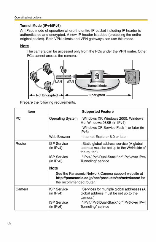
Tunnel Mode (IPv4/IPv6)An IPsec mode of operation where the entire IP packet including IP header is authenticated and encrypted. A new IP header is added (protecting the entire original packet). Both VPN clients and VPN gateways can use this mode.
NoteThe camera can be accessed only from the PCs under the VPN router. Other PCs cannot access the camera.
Prepare the following requirements.
Item Supported Feature
PC Operating System
Web Browser
: Windows XP, Windows 2000, Windows Me, Windows 98SE (in IPv4): Windows XP Service Pack 1 or later (in IPv6): Internet Explorer 6.0 or later
Router ISP Service (in IPv4)
ISP Service (in IPv6)
: Static global address service (A global address must be set up to the WAN side of the router.): "IPv4/IPv6 Dual-Stack" or "IPv6 over IPv4 Tunneling" service
NoteSee the Panasonic Network Camera support website at http://panasonic.co.jp/pcc/products/en/netwkcam/ for the recommended router.
Camera ISP Service (in IPv4)
ISP Service (in IPv6)
: Services for multiple global addresses (A global address must be set up to the camera.): "IPv4/IPv6 Dual-Stack" or "IPv6 over IPv4 Tunneling" service
EncryptedNot Encrypted
Tunnel ModeWANLAN

Operating Instructions
2.5 Encrypt the Camera Image in Transport ModeThe camera can encrypt the image using IPsec transport mode.
NoteIf you use IPsec, refresh interval slows down.
1. Click [IPsec] on the Setup page.
2. Click Camera in the Transport column.
• If you use transport mode in E-mail or FTP transfer, click No. in the Buffer/Transfer column.
NoteTo display Alarm Log, set Alarm 1, Alarm 2 or Motion Detection for Trigger Setting and check [Enable].
3. Enter each parameter in the data field.
The display shows that the communication is in HTTP and any people can access the camera if they have the pre-shared key. Set up these settings to transfer images in transport mode (see page 126).
Set to use Alarm Log (see page 131).
63

Operating Instructions
64
4. Click [Save] when finished.
• New settings are saved.
5. Click [Cancel].
• The IPsec page is displayed.
6. Check [Use] in the IPsec column, check encoding strength, and click [Save].
Setting Description
Status • Check the box to use this encryption method.
Pre-Shared Key • It is the key to use in the authentication of communications. Enter the same pre-shared key as your PC.
• Enter ASCII characters for the host name (see page 183). But [Space], ["], ['], [&], [<] and [>] are not available.
NoteIf the pre-shared key leaks to a third party, it may lead to illegal access, private information leak or interference. To protect your security and privacy, pay attention to the following points.• Make it known only to the specified people.• Set it as many characters as possible.• Change the password regularly.
Setting Description
IPsec • Check the box to enable IPsec features. If you clear the box, whole IPsec features will be invalid.
Encoding strength • Encoding strength for IPsec can be selected. If you select [Standard], DES or NULL is valid as an algorithm, and then the data will become easier to be decrypted.

Operating Instructions
7. Click [Restart].
8. Set up your PC as it fits to the requirements on page 61.
• Set the FTP server or E-mail server to transfer images.
9. Access the camera (see page 20).
• If you can access the camera, the IPsec setup is complete.
Note• In IPsec communications, "IPsec" is displayed on the Top page or the
Single Camera page.
• If you cannot communicate using IPsec, see page 20 of the Troubleshooting manual (for BB-HCM311) or page 60 of the Installation/Troubleshooting manual (for BB-HCM331) on the Setup CD-ROM.
• See the Panasonic Network Camera support website at http://panasonic.co.jp/pcc/products/en/netwkcam/ for the IPsec features.
65

Operating Instructions
66
2.6 Encrypt the Camera Image in Tunnel ModeThe camera can encrypt the image using IPsec tunnel mode.
Note• Do not set IPsec on the PCs under the VPN router. Communications may
be blocked.• If you use IPsec, refresh interval slows down.• The camera can be accessed only from the PCs under the VPN router.
Other PCs cannot access the camera.
1. Click [IPsec] on the Setup page.
2. Click Add in the Tunnel column.
3. Enter each parameter in the data field.

Operating Instructions
4. Click [Save] when finished.
• New settings are saved.
5. Click [Cancel].
• The IPsec page is displayed.
6. Check [Use] in the IPsec column, check encoding strength, and click [Save].
Setting Description
Status • Check the box to use this encryption method.
Pre-Shared Key • It is the key to use in the authentication of communications. Enter the same pre-shared key as your VPN router.
• Enter ASCII characters for the host name (see page 183). But [Space], ["], ['], [&], [<] and [>] are not available.
NoteIf the pre-shared key leaks to a third party, it may lead to illegal access, private information leak or interference. To protect your security and privacy, pay attention to the following points.• Make it known only to the specified people.• Set it as many characters as possible.• Change the password regularly.
Network address • Enter the destination network address.• Enter "IP address/Prefix length" in the data field.
Router address • Enter the WAN IP address of the VPN router on a destination network.
Note• IPv6 link-local address is not available.• The camera can be accessed only from the PCs under
the VPN router. Other PCs cannot access the camera.
67

Operating Instructions
68
7. Click [Restart].
8. Set up your VPN router as shown below.
• To use tunnel mode, you need to set up your VPN router.
Setting Description
IPsec • Check the box to enable IPsec features. If you clear the box, whole IPsec features will be invalid.
Encoding strength • Encoding strength for IPsec can be selected. If you select [Standard], DES or NULL is valid as an algorithm, and then the data will become easier to be decrypted.
IKE Items Settings
Phase 1 Authentication Method
Pre-shared Key Method
ID Specifies by address.
Mode Main mode*1
Diffie-Hellman MODP Group
Specifies 1 or 2.
Cipher Algorithm Select from DES-CBC, 3DES-CBC or AES-CBC (128, 192, 256 bits). (Multiple selections are available.)
Message-Digest Algorithm
HMAC-MD5, HMAC-SHA-1
Lifetime Specifies by 28800 s (Byte setting is not supported.)

Operating Instructions
• Set up the IPsec policy as shown below.
9. Access the camera (see page 20).
• If you can access the camera, the IPsec setup is complete.
Note• In IPsec communications, "IPsec" is displayed on the Top page or the
Single Camera page.• If you cannot communicate using IPsec, see page 20 of the
Troubleshooting manual (for BB-HCM311) or page 60 of the Installation/Troubleshooting manual (for BB-HCM331) on the Setup CD-ROM.
• See the Panasonic Network Camera support website at http://panasonic.co.jp/pcc/products/en/netwkcam/ for the IPsec features.
Phase 2 Mode Quick mode
PFS Specifies either of Off, D-H Group 1 or D-H Group 2.
Cipher Algorithm Select from DES-CBC, 3DES-CBC, AES-CBC (128, 192, 256 bits) or NULL. (Multiple selections are available.)
Message-Digest Algorithm
HMAC-MD5-96, HMAC-SHA-1-96
Lifetime Specifies by 28800 s (Byte setting is not supported.)
*1 The camera does not support aggressive mode.
Items Settings
Protocol ANY
Source Network Network address and subnet mask on the LAN side of the VPN router
Source IP address A global address on the WAN side of the VPN router
Destination Network A global address of the camera
Destination IP address A global address of the camera
IKE Items Settings
69

Operating Instructions
70
2.7 Using UPnP™ (Universal Plug and Play)UPnPTM can automatically configure your router to be accessed from the Internet. In order to use this feature, your router needs to support this feature and it must be enabled. Most router manufacturers disable this feature as the default setting. See http://panasonic.co.jp/pcc/products/en/netwkcam/ for details and see your router's manual for how to enable UPnPTM. After the UPnPTM is enabled on the router, set [Enable] for auto port forwarding.
NoteThe camera's UPnPTM does not support IPv6. Use this feature in IPv4.
1. Click [UPnP] on the Setup page.
2. Set up UPnP.
Setting Description
Auto Port Forwarding
• If the network setting is [Static] or [DHCP], enabling auto port forwarding allows you to access the camera from the Internet.
NoteIf the network setting is [Automatic Setup], enable [Allow Access from the Internet] on the Network page (see page 53).
Display Shortcut Icon in My Network Places
• Enabling it displays a shortcut to the camera in the My Network Places folder.
NoteIf you use Windows XP or Windows Me, this feature is available. Enable UPnPTM Windows component before using this feature (see page 182).

Operating Instructions
3. Click [Save] when finished.
• New settings are saved.• When finished, "Success!" is displayed.
4. Click [Go to UPnP page].
• The UPnP page is displayed.
2.7.1 Connecting the Camera to a Router Supporting UPnP™ (IPv4 Only)
To allow access from the Internet with a router supporting UPnPTM, follow the procedures shown on Getting Started.
Note• In some routers, the UPnPTM feature is disabled by default. Enable your
router's UPnPTM feature following the router manual before you set up the camera. See the Panasonic Network Camera support website at http://panasonic.co.jp/pcc/products/en/netwkcam/ for details.
• If the maximum idle time is set in PPPoE or PPTP connection with your ISP, disable it on the router. See the router manual for details.
71

Operating Instructions
72
2.7.2 Connecting the Camera to a Router Not Supporting UPnP™ (IPv4 Only)
To allow access from the Internet with a router not supporting UPnPTM, follow the procedures below.
1. Select [Static] on the Network (IPv4) page.
2. Enable port forwarding on the router.
Using the IP address and port number note written on step 1-(3), enable port forwarding on the router. See the router manual for how to enable port forwarding.
3. Register with a DynamicDNS service.
Port Forwarding feature*1 (IPv4 Only)The port forwarding feature is required to allow access from the Internet with a router not supporting UPnPTM. It exchanges a local IP address to a global one. Each camera must be assigned a unique port number.
(1) Access the camera (see page 20).(2) Click [Setup] tab at the top of the page.(3) Select [Static] on the Network page.
• The Static IP Address Configuration page is displayed. Make a note of the IP address and port number, since they are required to enable port forwarding on the router.
(4) Click [Save] without changing the settings.(5) Click [Restart].
*1 "Port forwarding" may be called "Address translation", "Static IP Masquerade", "Virtual server" or "Port mapping" in other products.
Global IP address of the router
vvv.xxx.yyy.zzz:80vvv.xxx.yyy.zzz:81
vvv.xxx.yyy.zzz:80 192.168.0.253:80vvv.xxx.yyy.zzz:81 192.168.0.252:81
Port No.Port Forwarding feature
Local IP address
The IP addresses shown above may differ from those offered on your home network.Note
192.168.0.1
192.168.0.252Port No. 81
192.168.0.253Port No. 80
RouterModem
CATVxDSLOptical cable
Internet

Operating Instructions
2.8 Registering with the DynamicDNS serviceDynamicDNS service is a service that allows you to assign an easy-to-remember name to the camera, similar to your favorite web site. DynamicDNS service also allows you to easily access the camera, even when your ISP changes the IP address. Panasonic Communications recommends you to register with it for the Internet access to the camera. See http://www.viewnetcam.com for details about the Viewnetcam.com service.Click [DynamicDNS] on the Setup page.
When you select [Disable]
• The DynamicDNS service is disabled.• Clicking [Cancel] cancels your settings without saving changes. When you select [Viewnetcam.com]
1. Click [Next].
• Clicking [Cancel] cancels your settings without saving changes.
2. Click [Save] when finished.
73

Operating Instructions
74
• New settings are saved.• When finished, the message dialog is displayed. • Clicking [Cancel] cancels your settings without saving changes.
3. Click [Go to Viewnetcam.com page].
• The Viewnetcam.com page is displayed.
4. Click Your Account Link.
• The Viewnetcam.com registration website is displayed.Note• When the Viewnetcam.com registration website is not displayed,
confirm that the URL is displayed in the right column of the Your Account Link. If the URL is not displayed, follow the procedures below.
• Personal (Camera) URL is available after you registered with the Viewnetcam.com service.
• If port forwarding is not enabled or your network is not connected to the Internet, the Viewnetcam.com service is not available.
5. Register with the Viewnetcam.com service following the website.
• The Viewnetcam.com page is displayed.
6. Access the camera with a registered URL from the Internet (see page 20).
• When the Top page is displayed, the Viewnetcam.com registration is complete.
Note• It may take a maximum of 30 minutes for the registered URL to work.• If "Expired" is displayed at the Personal (Camera) URL on the
Viewnetcam.com page or at the Camera URL in the DynamicDNS on the Status page, restart the camera. After that, confirm that your registered URL is displayed on their pages.
Setting Description
Personal (Camera) URL
• The camera's personal URL will be displayed after you register with the Viewnetcam.com service.
Your Account Link
• The URL is displayed to register with the Viewnetcam.com service. Clicking [Your Account Link] item name displays the Viewnetcam.com registration website.
1. Wait for a while, and click [Refresh] on the web browser.2. Confirm that your network (your PC and camera) is connected to
the Internet.

Operating Instructions
Confirming the Internet accessDue to the router specifications, the image may not be displayed even if you access the camera from your PC on the same LAN as the camera. In this case, access the camera in the following procedures.• Accessing from the PC on another network (see page 20)• Accessing from your mobile phone (see page 46) When you select [User-specified DynamicDNS]
1. Click [Next].
• Clicking [Cancel] cancels your settings without saving changes.
2. Set each parameter.
• You can get DynamicDNS information from the DynamicDNS service industry company.
3. Click [Save] after finished.
• New settings are saved.• When finished, "Success!" is displayed.
75

Operating Instructions
76
4. Click [Go to DynamicDNS page].
• The DynamicDNS page is displayed.
Note• It may take several minutes for the registered URL to connect.• Some DynamicDNS service is not connected.
Confirming the Internet accessDue to the router specifications, the image may not be displayed even if you access the camera from your PC on the same LAN as the camera. In this case, access the camera in the following procedures.• Accessing from the PC on another network (see page 20)• Accessing from your mobile phone (see page 46)
2.8.1 DynamicDNS Service (IPv4/IPv6)DynamicDNS allows you to choose an easy-to-remember address (such as "bob.viewnetcam.com") that you can use to view images from your camera over the Internet. This service is compatible with both IPv4 and IPv6 addresses. Some DynamicDNS service is not compatible with IPv6 address.
What is the advantage of DynamicDNS service?In order to view camera images over the Internet, you need to know your camera's global IP address. However, many Internet Service Providers (ISPs) assign their customers a "dynamic" IP address that changes monthly, weekly, or each time they log on. Unless you have been assigned a static IP address (an IP address that does not change periodically) by your ISP, you may find it difficult to access your camera over the Internet because your IP address changes periodically. Viewnetcam.com service allows you to access your camera even if your assigned global IP address changes.

Operating Instructions
How the DynamicDNS service works
1. Your ISP assigns a global IP address to your Internet access account that changes periodically. This is the address needed to access the camera over the Internet.
2. When your ISP assigned global IP address changes, your camera automatically notifies the DynamicDNS service server of the new address in the DynamicDNS. The camera notifies the DynamicDNS service server of the new address in DynamicDNS in the following cases.– When starting the camera– Depending the time to be set at the update interval– When clicking the [Save] button
3. The DynamicDNS server contacts a Domain Name System (DNS) and registers your new global IP address to your chosen DynamicDNS address (such as "bob.viewnetcam.com").
4. When you enter your DynamicDNS address in your web browser while away from home or the office, the DNS server looks up the global IP address assigned to your DynamicDNS address.
5. The DNS server finds your current global IP address and allows you to connect to your camera.
Note• Ask your ISP about what type of IP address you are using.• Some ISPs assign you a local IP address. In this case, you cannot use the
DynamicDNS service.
• If the camera is using a port number other than 80, the port number must be specified at the end of the DynamicDNS URL. For example: Using port 80: http://(Cameraname).viewnetcam.com Using any other port: http://(Cameraname).viewnetcam.com:Port Number
DynamicDNS service server
ISP
DNS server
Internet
New address registered with DNS server
Camera reports new address
Camera connection established
Global IP address changes
Off-site PC
On-site Network Camera
DNS looks up current address
3.
4.
2.
1.
5.
77

Operating Instructions
78
2.9 Setting Date and TimeThe Date and Time page allows you to set date and time. Date and time are used for each image (Single, Multi and Buffered), Trigger, Alarm Log and Operation Time.
NoteSaving the date and time settings deletes all buffered images on the internal memory. The buffered images on the SD memory card are not deleted.
1. Click [Date and Time] on the Setup page.
2. Set each parameter.
• Set [Automatic Time Adjustment] to synchronize the time automatically with an NTP server.
• Clicking [Cancel] cancels your settings without saving changes.

Operating Instructions
3. Click [Save] when finished.
• New settings are saved.• When finished, "Success!" is displayed.
4. Click [Go to Date and Time page].
• The Date and Time page is displayed.
Setting Description
Time Setting • Select date and format (AM/PM or 24 H). These settings are used for each image (Single, Multi and Buffered), Trigger, Alarm Log and Operation Time. But E-mail subject and file name by E-mail or FTP transfer uses only 24 h format.
Automatic Time Adjustment
• NTP (Network Time Protocol) server synchronizes the camera's internal clock. It adjusts automatically every day. Check the box to enable it.
• Set the NTP server IP address. In IPv4, set 4 digits (0—255) and 3 periods such as "192.168.0.253". But "0.0.0.0" and "255.255.255.255" are not available. In IPv6, set 8 hexadecimal digits divided with ":". Consecutive 0s can be abbreviated as "::". Or set a host name (1—255 characters).
• Select your time zone.
NoteThe camera will not synchronize to the NTP server if the time setting from the NTP server moves forward or backward more than 1 hour at a time. This is to protect the camera's time setting from fraudulent NTP server tampering, incorrect time information, etc.
Adjust Clock for Daylight Saving Time
• During the daylight saving time, the internal clock is turned forward an hour. The clock will shift one hour forward at the set time on the Start Day, and move back one hour at the set time on the End Day. Check the box to enable it.
NoteAn "s" is put between date and time of time stamp when enabling this feature. The time stamp will be attached to the transferred images by the Image Transfer feature.
79

Operating Instructions
80
NoteDate and time settings become incorrect depending on the length of power-on time or the internal temperature. Using the Automatic Time Adjustment is recommended.

Operating Instructions
2.10 Changing Camera SettingsThe Camera page allows you to set the camera name, white balance, pan/tilt range, return to specified position and color night view settings.
1. Click [Camera] on the Setup page.
2. Set each parameter.
• Clicking [Cancel] cancels your settings without saving changes.
81

Operating Instructions
82
Setting Description
Camera Name • The camera name is displayed on the Single Camera page.
• Enter ASCII characters (see page 183) or characters in each language (1—15 characters for a 1-byte character and 1—7 characters for a 2-byte character). But [Space], ["], ['], [&], [<], and [>] are not available.
White Balance Select from the following options.
• Auto (default) — Automatic adjustment
• Fixed Indoor — Electric bulb (2800 K)
• Fixed Fluorescent (White)
— White (3600 K)
• Fixed Fluorescent (Daylight)
— Daylight (4000 K)
• Fixed Outdoor — Solar light (6000 K)
• Hold — Setting [Hold] keeps the current white balance.
NoteWhite balance is also saved in the home position, alarm position and preset positions.
Pan Range*1 Select from the following options.
• Minimum — Current settings, -60—+60
• Home Position*2 — Current settings, -60—+60
• Maximum — Current settings, -60—+60
• The values must be selected as minimum home position maximum.
NoteIf you wrongly set the range, your privacy may be seen. Confirm the range after the setup.

Operating Instructions
Tilt Range*1 Select from the following options.
• Minimum — Current settings, -45—+20
• Home Position*2 — Current settings, -45—+20
• Maximum — Current settings, -45—+20
• The values must be selected as minimum home position maximum.
NoteIf you wrongly set the range, your privacy may be seen. Check the range after the setup.
Return to Specified Position
• If the camera is not operated during the specified period, the camera turns to the specified position.
• The following settings are available.– Time - Do not move, 10 s, 20 s, 30 s, 1 min, 5 min, 10
min, 30 min, 1 h– Specified Position - Home Position, Alarm No.1, Alarm
No.2, Preset No.1-20• If a preset position is deleted after the preset position is set
for Specified Position, a blank is displayed and the specified position does not work.
Note• A preset position (1—20) is displayed as a ("preset
number"."preset name"). (e.g.: 1.sample)
• A deleted preset position is displayed as a ("preset number".). (e.g.: 1.)
• If you did not set any presets, the camera cannot turn to the preset position.
Setting Description
83

Operating Instructions
84
3. Click [Save] when finished.
• New settings are saved. If the [Pan Range] or [Tilt Range] settings are changed, the camera turns to the home position.
• When finished, "Success!" is displayed.
4. Click [Go to Camera page].
• The Camera page is displayed.
Color Night View
• In the color night view mode, the camera image becomes brighter in a low illuminance. The camera image returns normal operation in a bright location.
• If you enable the color night view mode, refresh interval may slow down.
NoteIn the color night view mode, the image may have white or colored circles around the object. This is not a problem, since it is a CCD sensor characteristic.
*1 See page 85 for details about pan/tilt range settings.*2 These home position settings are displayed as you set on page 34.
Setting Description

Operating Instructions
Specifying Pan/Tilt Range1. Access the camera (see page 20), and click [Single] at the top of the Top page.
2. Open another web browser, and display the Camera page (see page 81).
3. Align the Single Camera page and the Camera page side to side.
4. Set the pan/tilt range.
• Selecting [Current Settings] displays the current angle of the camera. Select each value while adjusting the pan/tilt on the Single Camera page.
Note
The values must be selected as minimum home position maximum.
5. Click [Save] on the Camera page.
• New settings are saved. The camera turns to the home position.
Max.: +20 ˚
Max.: +60 ˚ Min.: -60 ˚
Min.: -45 ˚
85

Operating Instructions
86
2.11 Adjusting AudioThe Audio page allows you to adjust the built-in microphone, the use of external speaker, microphone sensitivity and external speaker volume.
1. Click [Audio] on the Setup page.
2. Set each parameter.
• Clicking [Cancel] cancels your settings without saving changes.

Operating Instructions
3. Click [Save] when finished.
• New settings are saved.• When finished, "Success!" is displayed.
4. Click [Go to Audio page].
• The Audio page is displayed.
Setting Description
Output • It controls audio output for external speaker connected to the camera.
Volume • It controls the volume to output to external speaker.Minimum: Turn down the volumeStandard: Standard setting (default)Maximum: Turn up the volume
PC Audio Input Timeout
• You can set the length of time to receive the audio from your PC.
• The following settings are available.1 min, 2 min, 3 min, 5 min, 10 min, 20 min, 30 min, 60 min
Input • It controls audio input from the built-in microphone or external microphone.
Camera Microphone Sensitivity
• You can select the built-in microphone or external microphone sensitivity.Minimum: Decreased sensitivityStandard: Standard setting (default)Maximum: Enhanced sensitivity
Mute during Pan/Tilt • You can temporarily stop listening (audio input) when the camera pans or tilts.
87

Operating Instructions
88
2.12 Changing Authentication Setting and Administrator User Name and Password
The Security: Administrator page allows you to change authentication, administrator user name and password. The authentication window is displayed, and allows the registered users to access the camera.Note• If you access the camera for the first time, the window to set administrator user
name and password is displayed. Make a note of the user name and password so that you will not forget them.
• The user name and password should be secured at your own responsibility. Pay attention to the following points.– Set the user name and password as many characters as possible.– Change the password regularly.
IMPORTANT• It is important to limit access to the camera by use of a unique User Name and
a secret Password. Because the camera is accessed through the Internet it is possible that the camera could be accessed by unknown individuals, including those who are commonly known as "crackers" to whom you do not want to allow access. The use of a unique User Name and a Password known only to you will help insure that only authorized individuals are given access to the camera. You have the option of proceeding without a User Name and Password, but it is strongly recommended that you utilize these protections.
1. Click [Administrator] on the Setup page.
2. Set each parameter.
• Clicking [Cancel] cancels your settings without saving changes.

Operating Instructions
Note• When setting authentication, set the user name and password, and save
them.• When users other than an administrator are accessing the camera,
[Setup] and [Maintenance] tab will not be displayed.• The user name and password are case sensitive.
3. Click [Save] when finished.
• New settings are saved.• When finished, "Success!" is displayed.
Setting Description
General Authentication
Authentication has 2 phases.• If you set [Permit access from guest users], the camera
does not display the authentication window in camera access. All guest users can view the image without user name and password.
NoteIf you set [Permit access from guest users], [Login] tab is displayed at the top of the page. After you log in as an administrator (see page 91), you can access the Setup page and the Maintenance page.
• If you set [Do not permit access from guest users], the camera displays authentication window in camera access. Users must enter the user name and password.
User Name/Password
• User Name (6 to 15 characters): Enter the user name.• Password (6 to 15 characters): Enter the password.
NoteThe password must be different from the user name.
• Retype Password: Reenter the password.• Enter ASCII characters (see page 183). But [Space], ["], ['],
[&], [<], [>] and [:] are not available.
89

Operating Instructions
90
4. Click [Go to Security: Administrator page].
• The Security: Administrator page is displayed.
Note• When the user name and password have been changed, the camera
displays an authentication window. Enter the user name and password, and click [OK].
Administrator/General Users/Guest UsersThe camera has 3 user levels (administrator, general users and guest users).
NoteGuest users mean unregistered users. Set [Permit access from guest users] on the Security: Administrator page (see page 88).
Items Administrator General Users Guest Users
User Name and Password
Required Required Not Required
Number of Users 1 50 —
Accessible Pages All Pages Pages Except For Setup and
Maintenance page
Pages Except For Setup and
Maintenance page
Access Level All Operations Access level can be set for each
general user (see page 92).
Access level can be set for guest users (see page
92).

Operating Instructions
2.13 Logging in to the CameraIf you set [Permit access from guest users] on the Security: Administrator page, [Login] tab is displayed at the top of the page. After you log in as an administrator, you can access the Setup page and the Maintenance page.
1. Click [Login] tab at the top of the page.
2. Check the login mode, and click [Login].
NoteThe authentication window is displayed. Enter the user name and password set for General Users or Administrator.
3. Enter a valid user name and password according to the Login mode selected in step 2, and click [OK].
91

Operating Instructions
92
2.14 Creating, Modifying or Deleting General UsersThe General User page allows you to create, modify or delete general users. Up to 50 general users can be registered. The access level is set for each general user. If you set [Permit access from guest users] on the Security: Administrator page, the access level can be set for guest users.
NoteFor general users, the Setup and Maintenance tabs are not displayed.
1. Click [General User] on the Setup page.
2. If you create a general user, click [Create].
• When setting [Do not permit access from guest users]
• When setting [Permit access from guest users]
• If you change the settings of general users or guest users, select their name and click [Modify]. The modification page is displayed.
• If you delete a general user, select the name and click [Delete]. The confirmation page is displayed.

Operating Instructions
3. Set each parameter.
• Settings for a general user • Settings for guest users
• Clicking [Cancel] takes you back to the previous page without saving changes.
Setting Description
User ID List • Up to 50 general users can be registered.• The list is used to modify or delete general user settings.
User Name/Password
• User Name (6 to 15 characters): Enter the user name.• Password (6 to 15 characters): Enter the password.
NoteThe password must be different from the user name.
• Retype Password: Reenter the password.• Enter ASCII characters (see page 183). But [Space], ["], ['],
[&], [<], [>] and [:] are not available.
93

Operating Instructions
94
4. Click [Save] when finished.
• New settings are saved.• When finished, "Success!" is displayed.
5. Click [Go to General User page].
Access Level Access level is set for each general user. Check the feature to enable.• In the limit time of continuous motion JPEG, set the time to
change the video (Motion JPEG) to still images for each user. (Not permitted, Unlimited, 10 seconds—60 minutes) In the refresh interval, set the refresh interval after the video changes to still images. (3—60 seconds)
• See each page for the following features.Pan/Tilt Control (see page 32)Preset Control (see page 31)Click to Center Control (see page 29)Brightness Control (see page 31)External Output Control (see page 31)Change Refresh Interval (see page 31)Change Resolution (see page 31)Change Quality (see page 31)Capture Image Button (see page 30)Listen (see page 38)Talk (see page 38)View Multi-Camera page (see page 41)View Buffered Image page (see page 43)
Setting Description

Operating Instructions
2.15 Buffering or Transferring Images by TimerThe Trigger page allows you to enable image buffer/transfer by E-mail or FTP.
1. Click [Trigger] on the Setup page.
2. Click No. to enable buffer/transfer.
3. Check [Enable Image Buffer/Transfer], and select [Timer] for trigger, and click [Next>].
Note• Click [Delete Buffered Images] to delete the buffered images.• Click [Save] to save the settings.
• Clicking [Cancel] takes you back to the Trigger page without saving changes.
95

Operating Instructions
96
4. Set the time, and click [Next>].
NoteThe timer works by an internal clock. Set the date and time before using timer buffer/transfer (see page 78).• Clicking [<Back] takes you back to the previous page.• Clicking [Cancel] takes you back to the Trigger page without saving
changes.
5. Set the image settings, and click [Next>].
Setting Description
Enable Image Buffer/Transfer
• Check the box to enable the Trigger setting. Clear the box to disable it.
Trigger • Selecting [Timer] enables the camera to buffer/transfer the image by timer.
• Selecting [Alarm 1 or 2] enables the camera to buffer/transfer the image by alarm signal.
• Selecting [Motion Detection] enables the camera to capture/transfer the images when the motion detects something.
Setting Description
A day of the week
• Check the box to enable the day. Clear the box to disable it.
Active Time of Trigger
• Select the [Always] option when you do not specify the time period. If you specify the time period, select the time period option and set the time period.

Operating Instructions
• Clicking [<Back] takes you back to the previous page.• Clicking [Cancel] takes you back to the Trigger page without saving
changes.
6. Set the image buffer frequencies, and click [Next>].
NoteDue to the network environment, object, number of accesses, enabling IPsec, the camera may not record the numbers of images as you set. In this case, set the image buffer frequencies longer.• Clicking [<Back] takes you back to the previous page.• Clicking [Cancel] takes you back to the Trigger page without saving
changes.
Setting Description
Image Resolution
• Select image resolution (640 x 480, 320 x 240 (default) or 160 x 120 pixels) to buffer or transfer.
Image Quality • Select the image quality.[Favor Clarity] optimizes for good quality.[Standard] offers standard quality. (default)[Favor Motion] optimizes for enhanced motion.[Mobile Phone] is for a transfer to a mobile phone.
Note640 x 480 pixels cannot be set for a transfer to a mobile phone.
Setting Description
Image Buffer Frequency
• Select the image buffer frequency to buffer or transfer the image. (1 image per hour—30 images per second)
97

Operating Instructions
98
7. Select the transfer method, and click [Next>].
• Clicking [<Back] takes you back to the previous page.• Clicking [Cancel] takes you back to the Trigger page without saving
changes.
NoteIf you transfer image by E-mail or FTP, confirm that the default gateway and DNS server addresses are assigned correctly (see page 51 and page 56).
Setting Description
No Transfer, No Memory Overwrite
• If the internal memory is full, the camera stops the buffer.
No Transfer, Memory Overwrite
• If the internal memory is full, the camera deletes the old images, and continues to buffer the image.
FTP • The camera transfers the image to an FTP server (see page 99).
E-mail • The camera transfers the image by E-mail (see page 101).

Operating Instructions
When you set [FTP] for Transfer MethodSelect [FTP], and click [Next>]. The following page is displayed.
• Clicking [<Back] takes you back to the previous page.• Clicking [Cancel] takes you back to the Trigger page without saving
changes.
99

Operating Instructions
10
Setting Description
Server IP Address or Host Name*1
*1 But [Space], ["], ['], [&], [<] and [>] are not available.
• If you set the server IP address, set 4 digits (0—255) and 3 periods such as "192.168.0.253". But "0.0.0.0" and "255.255.255.255" are not available. Or set a host name (1—255 characters).
• You can set IPv6 address.
Port No. • Enter a number (1—65535). Usually set to 21.
Login ID*2
*2 But ["] is not available.
• If your ISP requires a login ID, set it (0—63 characters).
Password*2 • If your ISP requires a password, set it (0—63 characters).
Login Timing • Select the login timing to an FTP server. If you set [One Time] during 1-minute transfer, the camera logs in to the server only once, and can reduce the time to log in or log out.
Upload File Name*1
• Set the file name to save on an FTP server. Enter 1—234 characters. Entering "\" creates directories for a file. (E.g. NetworkCamera\image.jpg)
Overwrite Setting
• Selecting [Overwrite File] saves and overwrites the image on the server. Selecting [Save as New File with Time Stamp] saves the image attaching time stamps on the file name, and the images are not overwritten.(E.g. image20050101093020500.jpg) Underlined numbers are "9h30min20s500ms on January 1, 2005". The letter "s" is inserted after the day when referring to a summer time zone.
Data Transfer Method
• Select [Passive Mode] normally. If FTP does not work, select [Active Mode] and check the operation.
0

Operating Instructions
When you set [E-mail] for Transfer MethodSelect [E-mail], and click [Next>]. The following page is displayed.
• Clicking [<Back] takes you back to the previous page.• Clicking [Cancel] takes you back to the Trigger page without saving
changes.
Note• The camera works only with an SMTP (Simple Mail Transfer Protocol)
server. It does not work with mail servers like "Hotmail®" using a web browser.
• The subject name by E-mail transfer uses only 24 h format. The file name is "image.jpg". E.g. "image:20050101093020500". Underlined numbers are "9h30min20s500ms on January 1, 2005". The letter "s" is inserted after the day when referring to a summer time zone.
101

Operating Instructions
10
Setting Description
SMTP Server IP Address or Host Name*1
*1 But [Space], ["], ['], [&], [<] and [>] are not available.
• If you set the server IP address, set 4 digits (0—255) and 3 periods such as "192.168.0.253". But "0.0.0.0" and "255.255.255.255" are not available. Or set a host name (1—255 characters).
• You can set IPv6 address.
Port No. • Enter a number (1—65535). Usually set to 25.
POP3 Server IP Address or Host Name*1
• If you set the server IP address, set 4 digits (0—255) and 3 periods such as "192.168.0.253". But "0.0.0.0" and "255.255.255.255" are not available. Or set a host name (0—255 characters).
• You can set IPv6 address.
Port No. • Enter a number (1—65535). Usually set to 110.
Login ID*2
*2 But ["] is not available.
• If your ISP requires a login ID to log in to a POP3 server, set it (0—63 characters).
Password*2 • If your ISP requires a password to log in to a POP3 server, set it (0—63 characters).
Reply E-mail Address*2
• Set the sender's E-mail address. We recommend you to set the administrator's E-mail address.
Destination E-mail Address*2 1—3
• Set the destination E-mail address (up to 3).
Subject*2 • Enter a subject with ASCII characters (see page 183) or characters in each language (0—44 characters for a 1-byte character and 0—22 characters for a 2-byte character).
Text • Enter text with ASCII characters (see page 183) or characters in each language (0—63 characters for a 1-byte character and 0—31 characters for a 2-byte character). But ["] and [end-of-line] key are not available.
2

Operating Instructions
8. Confirm the settings, and click [Save].
• New settings are saved.• When finished, "Success!" is displayed.
9. Click [Go to Trigger page].
• The Trigger page is displayed.Note• If you are buffering images on the internal memory, the following
operations also delete all buffered images.– Turning off the camera.– Saving the Date and Time page.– Restarting, updating firmware or resetting the camera to factory
default.
103

Operating Instructions
10
2.16 Buffering or Transferring Images by Alarm Signal
The Trigger page allows you to enable image buffer/transfer by E-mail or FTP.
1. Click [Trigger] on the Setup page.
2. Click No. to enable buffer/transfer.
3. Check [Enable Image Buffer/Transfer], select [Alarm 1 or 2] for trigger, select [Rising: GND to Open (High).] or [Falling: Open (High) to GND.] and click [Next>].
Note• Click [Delete Buffered Images] to delete this buffered images.
• Click [Save] to save the settings.• Clicking [Cancel] takes you back to the Trigger page without saving
changes.
4

Operating Instructions
4. Set the time, and click [Next>].
NoteThe timer works by an internal clock. Set the date and time before using timer buffer/transfer (see page 78).
• Clicking [<Back] takes you back to the previous page.• Clicking [Cancel] takes you back to the Trigger page without saving
changes.
Setting Description
Enable Image Buffer/Transfer
• Check the box to enable the Trigger setting. Clear the box to disable it.
Trigger • Selecting [Timer] enables the camera to buffer/transfer the image by timer.
• Selecting [Alarm 1 or 2] enables the camera to buffer/transfer the image by alarm signal.
• Selecting [Motion Detection] enables the camera to capture/transfer the images when the motion detects something.
Alarm enable condition
• Selecting the method of the detection for an alarm connected to the External I/O terminal.
• Select [Rising: GND to Open (High).] or [Falling: Open (High) to GND.]. [Rising: GND to Open (High).] is the state that GND pin and pin 1 or pin 2 is left open. [Falling: Open (High) to GND.] is the state that GND pin and pin 1 or pin 2 is short-circuited. (See page 158)
Setting Description
A day of the week
• Check the box to enable the day. Clear the box to disable it.
Active Time of Trigger
• Select the [Always] option when you do not specify the time period. If you specify the time period, select the time period option and set the time period.
105

Operating Instructions
10
5. Set the Lens Position When Triggered setting, and click [Next>].
NoteIf you enable the Lens Position When Triggered setting, buffer/transfer starts after the camera turns to the Home Position, registered Preset No.1–20 or Alarm No.1–2.• Clicking [<Back] takes you back to the previous page.• Clicking [Cancel] takes you back to the Trigger page without saving
changes.
6. Set the image settings, and click [Next>].
• Clicking [<Back] takes you back to the previous page.• Clicking [Cancel] takes you back to the Trigger page without saving
changes.
Setting Description
Lens Position When Triggered
• Set [Move to alarm position] to move the lens to the Home Position, alarm position (see page 34) or Preset 1–20 when the alarm signal is detected.
Setting Description
Image Resolution
• Select image resolution (640 x 480, 320 x 240 (default) or 160 x 120 pixels) to buffer or transfer.
6

Operating Instructions
7. Set the image buffer frequencies, and click [Next>].
NoteDue to the network environment, object, number of accesses, enabling IPsec, the camera may not record the numbers of images as you set. In this case, set the image buffer frequencies longer.
• Clicking [<Back] takes you back to the previous page.• Clicking [Cancel] takes you back to the Trigger page without saving
changes.
Image Quality • Select the image quality.[Favor Clarity] optimizes for good quality.[Standard] offers standard quality. (default)[Favor Motion] optimizes for enhanced motion.[Mobile Phone] is for a transfer to a mobile phone.
Note640 x 480 pixels cannot be set for a transfer to a mobile phone.
Setting Description
Enable Pre-trigger Image Buffer
• Check the box to enable the setting. The camera buffers or transfers the image right before the alarm signal is detected.
• Set an interval, number of images to buffer and total number. The buffered images may not match the total number due to memory capacity, image resolution, image quality or what object you view.
Setting Description
107

Operating Instructions
10
8. Select the transfer method, and click [Next>].
• Clicking [<Back] takes you back to the previous page.• Clicking [Cancel] takes you back to the Trigger page without saving
changes.
NoteIf you transfer image by E-mail or FTP, confirm that the default gateway and DNS server addresses are assigned correctly (see page 51 and page 56).
Enable Post-trigger Image Buffer
• Check the box to enable the setting. The camera buffers or transfers the image right after the alarm signal is detected.
• Set an interval, number of images to buffer and total number. The buffered images may not match the total number due to memory capacity, image resolution, image quality or what object you view.
Setting Description
No Transfer, No Memory Overwrite
• If the internal memory is full, the camera stops the buffer.
No Transfer, Memory Overwrite
• If the internal memory is full, the camera deletes the old images, and continues to buffer the image.
FTP • The camera transfers the image to an FTP server (see page 109).
E-mail • The camera transfers the image by E-mail (see page 111).
Setting Description
8

Operating Instructions
When you set [FTP] for Transfer MethodSelect [FTP], and click [Next>]. The following page is displayed.
• Clicking [<Back] takes you back to the previous page.• Clicking [Cancel] takes you back to the Trigger page without saving
changes.
109

Operating Instructions
11
Setting Description
Server IP Address or Host Name*1
*1 But [Space], ["], ['], [&], [<] and [>] are not available.
• If you set the server IP address, set 4 digits (0—255) and 3 periods such as "192.168.0.253". But "0.0.0.0" and "255.255.255.255" are not available. Or set a host name (1—255 characters).
• You can set IPv6 address.
Port No. • Enter a number (1—65535). Usually set to 21.
Login ID*2
*2 But ["] is not available.
• If your ISP requires a login ID, set it (0—63 characters).
Password*2 • If your ISP requires a password, set it (0—63 characters).
Login Timing • Select the login timing to an FTP server. If you set [One Time] during 1-minute transfer, the camera logs in to the server only once, and can reduce the time to log in or log out.
Upload File Name*1
• Set the file name to save on an FTP server. Enter 1—234 characters. Entering "\" creates directories for a file. (E.g. NetworkCamera\image.jpg)
Overwrite Setting
• Selecting [Overwrite File] saves and overwrites the image on the server. Selecting [Save as New File with Time Stamp] saves the image attaching time stamps on the file name, and the images are not overwritten.(E.g. image20050101093020500.jpg) Underlined numbers are "9h30min20s500ms on January 1, 2005". The letter "s" is inserted after the day when referring to a summer time zone.
Data Transfer Method
• Select [Passive Mode] normally. If FTP does not work, select [Active Mode] and check the operation.
0

Operating Instructions
When you set [E-mail] for Transfer MethodSelect [E-mail], and click [Next>]. The following page is displayed.
• Clicking [<Back] takes you back to the previous page.• Clicking [Cancel] takes you back to the Trigger page without saving
changes.
Note• The camera works only with an SMTP (Simple Mail Transfer Protocol)
server. It does not work with mail servers like "Hotmail" using a web browser.
• The subject name by E-mail transfer uses only 24 h format. The file name is "image.jpg". E.g. "image:20050101093020500". Underlined numbers are "9h30min20s500ms on January 1, 2005". The letter "s" is inserted after the day when referring to a summer time zone.
111

Operating Instructions
11
Setting Description
SMTP Server IP Address or Host Name*1
*1 But [Space], ["], ['], [&], [<] and [>] are not available.
• If you set the server IP address, set 4 digits (0—255) and 3 periods such as "192.168.0.253". But "0.0.0.0" and "255.255.255.255" are not available. Or set a host name (1—255 characters).
• You can set IPv6 address.
Port No. • Enter a number (1—65535). Usually set to 25.
POP3 Server IP Address or Host Name*1
• If you set the server IP address, set 4 digits (0—255) and 3 periods such as "192.168.0.253". But "0.0.0.0" and "255.255.255.255" are not available. Or set a host name (0—255 characters).
• You can set IPv6 address.
Port No. • Enter a number (1—65535). Usually set to 110.
Login ID*2
*2 But ["] is not available.
• If your ISP requires a login ID to log in to a POP3 server, set it (0—63 characters).
Password*2 • If your ISP requires a password to log in to a POP3 server, set it (0—63 characters).
Reply E-mail Address*2
• Set the sender's E-mail address. We recommend you to set the administrator's E-mail address.
Destination E-mail Address*2 1—3
• Set the destination E-mail address (up to 3).
Subject*2 • Enter a subject with ASCII characters (see page 183) or characters in each language (0—44 characters for a 1-byte character and 0—22 characters for a 2-byte character).
Text • Enter text with ASCII characters (see page 183) or characters in each language (0—63 characters for a 1-byte character and 0—31 characters for a 2-byte character). But ["] and [end-of-line] key are not available.
2

Operating Instructions
9. After you confirm the settings and click [Next>], set E-mail notification and click [Next>].
• If you select [Enable], the E-mail Notification When Triggered page is displayed. Enter the settings seeing page 111 and page 112.
10. Click [Save] after confirming the settings.
• New settings are saved.• When finished, "Success!" is displayed.
Setting Description
Disable • The camera does not send an E-mail notification when buffering or transferring image.
Enable • The camera sends an E-mail notification (up to 3 destinations) when buffering or transferring image.
113

Operating Instructions
11
11. Click [Go to Trigger page].
• The Trigger page is displayed.Note• If you set a short interval to transfer image to a mobile phone, many E-
mails may be sent to it leading to a large phone bill. Therefore, we recommend you to set a long interval. 1 image per minute frequency is recommended.
• Alarm transfer stops its operations until the camera finishes all transfers. For example, if the camera transfers 3 images per minute and 6 images in total, the alarm detection will be in the following operation.
• If you are buffering images on the internal memory, the following operations also delete all buffered images.– Turning off the camera.– Saving the Date and Time page.– Restarting, updating firmware or resetting the camera to factory
default.
Detectable DetectableUndetectable
1st 2nd 3rd 4th 5th 6th
120 seconds
An alarm signal is detected.
4

Operating Instructions
2.17 Buffering or Transferring Images by Motion Detection Signal
The Trigger page allows you to enable image buffer/transfer by E-mail or FTP.
1. Click [Trigger] on the Setup page.
2. Click [No.] to enable buffer/transfer.
3. Check [Enable Image Buffer/Transfer], select [Motion Detection] for trigger, and click [Next>].
Note• Click [Delete Buffered Images] to delete this buffered images. • Click [Save] to save the settings.
• Clicking [Cancel] takes you back to the Trigger page without saving changes.
Setting Description
Enable Image Buffer/Transfer
• Check the box to enable the Trigger setting. Clear the box to disable it.
115

Operating Instructions
11
4. Set the time, and click [Next>].
NoteThe timer works by an internal clock. Set the date and time before using timer buffer/transfer (see page 78). • Clicking [>Back] takes you back to the previous page.• Clicking [Cancel] takes you back to the Trigger page without saving
changes.
5. Set the image settings, and click [Next>].
Trigger • Selecting [Timer] enables the camera to buffer/transfer the image by timer.
• Selecting [Alarm 1 or 2] enables the camera to buffer/transfer the image by alarm signal.
• Selecting [Motion Detection] enables the camera to capture/transfer the images when the motion detects something.
Setting Description
A day of the week
• Check the box to enable the day. Clear the box to disable it.
Active Time of Trigger
• Select the [Always] option when you do not specify the time period. If you specify the time period, select the time period option and set the time period.
Setting Description
6

Operating Instructions
NoteIf you enable the Lens Position When Triggered setting, buffer/transfer starts after the camera turns to the Home Position, registered Preset No.1–20, or Alarm No.1–2.
• Clicking [>Back] takes you back to the previous page.• Clicking [Cancel] takes you back to the Trigger page without saving
changes.
6. Set the image settings, and click [Next>].
• Clicking [>Back] takes you back to the previous page.• Clicking [Cancel] takes you back to the Trigger page without saving
changes.
Setting Description
Lens Position When Triggered
• Set [Move to alarm position] to move the lens to the Home Position, alarm position (see page 34) or Preset 1–20 when the alarm signal is detected.
Setting Description
Image Resolution
• Select image resolution (640 × 480, 320 × 240 (default) or 160 × 120 pixels) to buffer or transfer.
Image Quality • Select the image quality.[Favor Clarity] optimizes for good quality. [Standard] offers standard quality. (Default)[Favor Motion] optimizes for enhanced motion. [Mobile Phone] is for a transfer to a mobile phone.
Note640 × 480 pixels cannot be set for a transfer to a mobile phone.
117

Operating Instructions
11
7. Set the image buffer frequencies, and click [Next>].
NoteDue to the network environment, object, number of accesses, enabling IPsec, the camera may not record the numbers of images as you set. In this case, set the image buffer frequencies longer.• Clicking [Cancel] takes you back to the Trigger page without saving
changes.• Clicking [<Back] takes you back to the previous page.
Setting Description
Enable Pre-trigger Image Buffer
• Check the box to enable the setting. The camera buffers or transfers the image right before the motion detection signal is detected.
• Set an interval, number of images to buffer and total number. The buffered images may not match the total number due to memory capacity, image resolution, image quality or what object you view.
Enable Post-trigger Image Buffer
• Check the box to enable the setting. The camera buffers or transfers the image right after the motion detection signal is detected.
• Set an interval, number of images to buffer and total number. The buffered images may not match the total number due to memory capacity, image resolution, image quality or what object you view.
8

Operating Instructions
8. Select the transfer method, and click [Next>].
• Clicking [<Back] takes you back to the previous page.• Clicking [Cancel] takes you back to the Trigger page without saving
changes.
NoteIf you transfer image by E-mail or FTP, confirm that the default gateway and DNS server addresses are assigned correctly (see page 51 and page 56).
Setting Description
No Transfer, No Memory Overwrite
• If the internal memory is full, the camera stops the buffer.
No Transfer, Memory Overwrite
• If the internal memory is full, the camera deletes the old images, and continues to buffer the image.
FTP • The camera transfers the image to an FTP server (see page 120).
E-mail • The camera transfers the image by E-mail (see page 122).
119

Operating Instructions
12
When you set [FTP] for Transfer MethodSelect [FTP], and click [Next>]. The following page is displayed.
• Clicking [<Back] takes you back to the previous page.• Clicking [Cancel] takes you back to the Trigger page without saving
changes.
0

Operating Instructions
Setting Description
Server IP Address or Host Name*1
*1 But [Space], ["], ['], [&], [<] and [>] are not available.
• If you set the server IP address, set 4 digits (0—255) and 3 periods such as "192.168.0.253". But "0.0.0.0" and "255.255.255.255" are not available. Or set a host name (1—255 characters).
• You can set IPv6 address.
Port No. • Enter a number (1—65535). Usually set to 21.
Login ID*2
*2 But ["] is not available.
• If your ISP requires a login ID, set it (0—63 characters).
Password*2 • If your ISP requires a password, set it (0—63 characters).
Login Timing • Select the login timing to an FTP server. If you set [One Time] during 1-minute transfer, the camera logs in to the server only once, and can reduce the time to log in or log out.
Upload File Name*1
• Set the file name to save on an FTP server. Enter 1—234 characters. Entering "\" creates directories for a file. (E.g. NetworkCamera\image.jpg)
Overwrite Setting
• Selecting [Overwrite File] saves and overwrites the image on the server. Selecting [Save as New File with Time Stamp] saves the image attaching time stamps on the file name, and the images are not overwritten.(E.g. image20050101093020500.jpg) Underlined numbers are "9h30min20s500ms on January 1, 2005". The letter "s" is inserted after the day when referring to a summer time zone.
Data Transfer Method
• Select [Passive Mode] normally. If FTP does not work, select [Active Mode] and check the operation.
121

Operating Instructions
12
When you set [E-mail] for Transfer MethodSelect [E-mail], and click [Next>]. The following page is displayed.
• Clicking [<Back] takes you back to the previous page.• Clicking [Cancel] takes you back to the Trigger page without saving
changes.
Note• The camera works only with an SMTP (Simple Mail Transfer Protocol)
server. It does not work with mail servers like "Hotmail" using a web browser.
• The subject name by E-mail transfer uses only 24 h format. The file name is "image.jpg". E.g. "image:20050101093020500". Underlined numbers are "9h30min20s500ms on January 1, 2005". The letter "s" is inserted after the day when referring to a summer time zone.
2

Operating Instructions
Setting Description
SMTP Server IP Address or Host Name*1
*1 But [Space], ["], ['], [&], [<] and [>] are not available.
• If you set the server IP address, set 4 digits (0—255) and 3 periods such as "192.168.0.253". But "0.0.0.0" and "255.255.255.255" are not available. Or set a host name (1—255 characters).
• You can set IPv6 address.
Port No. • Enter a number (1—65535). Usually set to 25.
POP3 Server IP Address or Host Name*1
• If you set the server IP address, set 4 digits (0—255) and 3 periods such as "192.168.0.253". But "0.0.0.0" and "255.255.255.255" are not available. Or set a host name (0—255 characters).
• You can set IPv6 address.
Port No. • Enter a number (1—65535). Usually set to 110.
Login ID*2
*2 But ["] is not available.
• If your ISP requires a login ID to log in to a POP3 server, set it (0—63 characters).
Password*2 • If your ISP requires a password to log in to a POP3 server, set it (0—63 characters).
Reply E-mail Address*2
• Set the sender's E-mail address. We recommend you to set the administrator's E-mail address.
Destination E-mail Address*2 1—3
• Set the destination E-mail address (up to 3).
Subject*2 • Enter a subject with ASCII characters (see page 183) or characters in each language (0—44 characters for a 1-byte character and 0—22 characters for a 2-byte character).
Text • Enter text with ASCII characters (see page 183) or characters in each language (0—63 characters for a 1-byte character and 0—31 characters for a 2-byte character). But ["] and [end-of-line] key are not available.
123

Operating Instructions
12
9. After you confirm the settings and click [Next>], set E-mail notification and click [Next>].
• If you select [Enable], the E-mail Notification When Triggered page is displayed. Enter the settings seeing page 122 and page 123.
10. Click [Save] after confirming the settings.
• New settings are saved.• When finished, "Success!" is displayed.
Setting Description
Disable • The camera does not send an E-mail notification when buffering or transferring image.
Enable • The camera sends an E-mail notification (up to 3 destinations) when buffering or transferring image.
4

Operating Instructions
11. Click [Go to Trigger page].
• The Trigger page is displayed.Note• If you set a short interval to transfer image to a mobile phone, many E-
mails may be sent to it leading to a large phone bill. Therefore, we recommend you to set a long interval. 1 image per minute frequency is recommended.
• Motion Detection transfer stops its operations until the camera finishes all transfers. For example, if the camera transfers 3 images per minute and 6 images in total, the Motion Detection will be in the following operation.
• If you are buffering images on the internal memory, the following operations also delete all buffered images.– Turning off the camera.– Saving the Date and Time page.– Restarting, updating firmware or resetting the camera to factory
default.
Note• A change due to light or wind may detect motions mistakenly.• Motion detection level is changed depending on resolution, image quality,
and object situation. Confirm the level by performing motion detection recording.
• Enabling Motion Detection delays the frame rate of the camera.• Objects moving fast may not be detected.• Motion Detection may not work in the dark.
Detectable DetectableUndetectable
1st 2nd 3rd 4th 5th 6th
120 seconds
A Motion Detection signal is detected.
125

Operating Instructions
12
2.18 Transfer the Camera Image in Transport ModeThe camera can transfer the image in transport mode by E-mail or FTP.
Prepare the following requirements.
See page 63 and set up the E-mail or FTP server.
Item Supported Feature
E-mail or FTP Server
Operating SystemISP Service
: IPsec supported
: Services for multiple static global addresses (A global address must be set up to the server.)
Camera ISP Service : Services for multiple static global addresses (A global address must be set up to the camera.)
Transport Mode
Encrypted
E-mail or FTP Server
6

Operating Instructions
2.19 Transfer the Camera Image in Tunnel ModeThe camera can transfer the image in tunnel mode by E-mail or FTP.
Prepare the following requirements.
See page 66 and set up the E-mail or FTP server.
Item Supported Feature
VPN Router ISP Service (in IPv4)
ISP Service (in IPv6)
: Services for static global addresses (A global address must be set up to the WAN side.): "IPv4/IPv6 Dual-Stack" or "IPv6 over IPv4 Tunneling" service
Camera ISP Service (in IPv4)
ISP Service (in IPv6)
: Services for multiple static global addresses (A global address must be set up to the camera.): "IPv4/IPv6 Dual-Stack" or "IPv6 over IPv4 Tunneling" service
EncryptedNot Encrypted
Tunnel ModeVPN Router
WANLAN
E-mail or FTP Server
127

Operating Instructions
12
2.20 Setting the Motion DetectionThe Motion Detection page allows you to adjust sensitivity of the Motion Detection. Threshold: If the threshold is set low, this function sensitively detects changes.Sensitivity: If you set sensitivity high, amplitude of motion detection bar gets jumpy.
1. Click [Motion Detection] on the Setup page.
2. Click the Motion Detection bar in Threshold to set the threshold level.
3. Click the Motion Detection bar in Sensitivity to set the sensitivity level.
4. Click [Save] to save the settings.
• Clicking [Cancel] cancels your settings without saving changes
5. Click [Go to Motion Detection page].
• The Motion Detection page is displayed.
NoteThe Motion Detection feature does not work during pan/tilt operation.
PreviewDisplay current threshold and detection level.• The threshold is displayed by between green and red bar.• The detection level is displayed by between dark and light color.
NoteSetting Threshold and Sensitivity is enabled after saving, and reflect to preview.
Setting Description
Threshold • Adjust the threshold for Motion Detection.
Sensitivity • If you set sensitivity high, amplitude of motion detection bar gets jumpy.
8

Operating Instructions
What is the threshold?The threshold is a value for the camera to detect motions on the image during the motion detection buffering. Setting the threshold lower allows subtler changes to be detected. Setting the threshold higher allows bigger changes that might occupy half the image to be detected.
What is the sensitivity?The sensitivity is the brightness change level for the camera to detect as the motion. The high sensitivity setting enables the camera to detect the slight brightness change. Lower the sensitivity to make the camera to detect only the big brightness change.
NoteLowering the threshold and heightening sensitivity enable the camera easily to detect the trivial motion on the part of the image.
Threshold
Detect motions according to the threshold.
When the level exceeds the threshold, the camera detects motions.
129

Operating Instructions
13
Note• The motion detection is activated by object outline's changes and the
brightness changes. This feature is designed to alleviate false detections by overall brightness changes due to sunlight. But in this case, the camera may falsely detect the rapid brightness changes by the artificial light such as the fluorescent light. In other cases, motion detection by the Network Camera Recorder detects whole objects and brightness changes. The way to detect motion differs between the camera and Network Camera Recorder. Additionally, if the object's color is absorbed by the background color, the camera is hard to detect the motions.
• The detecting level depends on the object, resolution, or image quality. Confirm the condition on the Preview window with following the above procedure when setting the Motion Detection.
0

Operating Instructions
2.21 Notifying Setup of an Alarm LogOnce a day, an alarm log sent at a specified time can be checked. To enable Alarm Log, set Alarm 1, Alarm 2 or Motion Detection for Trigger Setting and check [Enable].
1. Click [Alarm Log] on the Setup page.
When selecting Alarm1, Alarm2 or Motion Detection in Trigger page, the Alarm log window is displayed.
2. Set each parameter.
Note• Click [Save] to save the settings.• Clicking [Cancel] cancels your settings without saving changes.
131

Operating Instructions
13
Setting Description
A setup of operation • Alarm log operation can be set here.
Time • Set the date and time to send alarm logs via E-mail.
SMTP Server IP Address or Host Name*1
*1 But [Space], ["], ['], [&], [<] and [>] are not available.
• If you set the server IP address, set 4 digits (0—255) and 3 periods such as "192.168.0.253". But "0.0.0.0" and "255.255.255.255" are not available. Or set a host name (1—255 characters).
• An IPv6 address can be set.
Port No. • Enter a number (1—65535). Usually set to 25.
POP3 Server IP Address or Host Name*1
• If you set the server IP address, set 4 digits (0—255) and 3 periods such as "192.168.0.253". But "0.0.0.0" and "255.255.255.255" are not available. Or set a host name (1—255 characters).
• An IPv6 address can be set.
Port No. • Enter a number (1—65535). Usually set to 110.
Login ID*2
*2 But ["] is not available.
• If your ISP requires a login ID to log in to a POP3 server, set it (0—63 characters).
Password*2 • If your ISP requires a password to log in to a POP3 server, set it (0—63 characters).
Reply E-mail Address*2
• Set the sender's E-mail address. We recommend you to set the administrator's E-mail address.
Destination E-mail Address 1-3*2
• Set the destination E-mail address (up to 3).
Subject • Enter a subject with ASCII characters (see page 183) or characters in each language (0—44 characters for a 1-byte character and 0—22 characters for a 2-byte character). But ["] is not available.
2

Operating Instructions
2.22 Changing Initial Settings on the Single Camera page or the Multi-Camera page
The Image Display page allows you to change initial settings (display settings when a user accesses the camera) of image resolution, image quality and refresh interval. You can display a time stamp on the image. The initial language can be selected from eight languages. The banner can be displayed for administrator or general users or both.
1. Click [Image Display] on the Setup page.
2. Set each parameter.
• Clicking [Cancel] cancels your settings without saving changes.
133

Operating Instructions
13
Setting Description
Image Resolution • Select the image resolution.640 x 480 pixels (Only for the Single Camera page)320 x 240 pixels (default)160 x 120 pixels (Only for the Multi-Camera page)
Image Quality • Select the image quality.[Favor Clarity] optimizes for good quality.[Standard] offers standard quality. (Default)[Favor Motion] optimizes for enhanced motion.
Refresh Interval • Select a refresh interval. Motion, 3 s, 5 s, 10 s, 30 s, and 60 s
Time stamp setting • You can display a time stamp on the upper left side of the image. Select from [Enable] or [Disable].
Note• If you enable this feature, the time is also stamped
on the buffered image.
• Set AM/PM format and 24H format on the Date and Time page.
Language • Select the initial language from English, French, German, Italian, Spanish, Russian, Simplified Chinese or Japanese. The selected language is displayed as the initial language on the Top, Single Camera, Multi-Camera and Buffered Image pages. If you select English or Japanese, all pages can be changed. But if you select other language, the Setup, Maintenance and Support pages are displayed only in English.
Banner Display • When the camera accesses the Internet, the banner displays product information about cameras or announcements about the latest firmware, etc. from Panasonic. Checking [Display] for Administrator is particularly recommended.
• When checked, the banner is displayed for administrator or general users or both.
• The banner is displayed only on the Single Camera page (see page 24).
4

Operating Instructions
3. Click [Save] when finished.
• New settings are saved.• When finished, "Success!" is displayed.
4. Click [Go to Image Display page].
• The Image Display page is displayed.
135

Operating Instructions
13
2.23 Configuring Multiple CamerasThe Multi-Camera Setup page allows you to configure the camera IP addresses and camera names to view multiple images on the Multi-Camera page. These configurations are required to use the Multi-Camera page. Up to 12 cameras can be configured.
1. Click [Multi-Camera] on the Setup page.
2. Click [Add].
Note• If you click the camera number, the modification page is displayed. The
camera setting can be modified or deleted on it.• If you configured multiple cameras, you can change the camera number.
Select the number, and click [Move].
3. Set each parameter.
• Clicking [Cancel] cancels your settings without saving changes.
6

Operating Instructions
Note• Set the local IP address and port number for the camera on the same
LAN.• If the cameras will be accessed from the Internet, be sure to use the global
IP address. In this situation, local IP addresses such as 192.168. x.x cannot be used.
4. Click [Save] when finished.
• New settings are saved.• The Multi-Camera Setup page is displayed.
Setting Description
Display • Check the box to enable the camera.
IP Address*1 or Host Name*2
• Set the IP address or the host name to enable the camera.
Port No. • Set the port number (1—65535).
Camera Name*3 • This camera name is displayed only on the Multi-Camera page.
*1 In IPv4, set 4 digits (0—255) and 3 periods such as "192.168.0.253". But "0.0.0.0" and "255.255.255.255" are not available.In IPv6, set the host name.
*2 Enter ASCII characters for the host name (see page 183). But [Space], ["], ['], [#], [&], [%], [=], [+], [?], [<] and [>] are not available.Enter 1—255 characters.
*3 Enter ASCII characters (see page 183) or characters in each language (1—15 characters for a 1-byte character and 1—7 characters for a 2-byte character). But [Space], ["], ['], [#], [&], [%], [=], [+], [?], [:], [<], and [>] are not available.
137

Operating Instructions
13
2.24 Format the SD memory cardBefore you record the camera image, you need to format the SD memory card.
Note• You can confirm the SD memory capacity on the Status page (see page
146).
1. Insert the SD memory card (see page 157).
2. Click [Trigger] on the Setup page.
3. Click [Format].
4. Click [OK] on the confirmation window.
• Format is complete.
5. Click [Go to Trigger page].
• The Trigger page is displayed.
8

Operating Instructions
2.25 Stop the SD Memory RecordingAfter you stop the SD memory recording, remove the SD memory card.
Note• You can confirm the SD memory capacity on the Status page (see page
146).• If the camera is restarted (see page 148), the SD memory recording starts
again.• If you remove the SD memory card and insert it again, the SD memory
recording starts again (see page 157).
1. Click [Trigger] on the Setup page.
2. Click [SD video recording stop].
3. Click [OK] on the confirmation window.
• The SD memory recording is stopped.
4. Click [Go to Trigger page].
• The Trigger page is displayed.
NoteEnsure that recording has stopped before removing the SD memory card. Do not remove the SD memory card, nor restart or turn off the camera while recording images on the card. Doing so can cause a decrease in SD memory card capacity, data corruption or camera malfunction.
139

Operating Instructions
14
2.26 Start the SD Memory RecordingThe SD memory recording can be started on the Trigger page.
Note• You can confirm the SD memory capacity on the Status page (see page
146).• If the camera is restarted (see page 148), the SD memory recording starts
again.• If you remove the SD memory card and insert it again, the SD memory
recording starts again (see page 157).
1. Click [Trigger] on the Setup page.
2. Click [SD video recording start].
• "SD video recording was started." is displayed.
3. Click [Go to Trigger page].
• The Trigger page is displayed.
NoteEnsure that recording has stopped before removing the SD memory card. (See page 139) Do not remove the SD memory card, nor restart or turn off the camera while recording images on the card. Doing so can cause a decrease in SD memory card capacity, data corruption or camera malfunction.
0
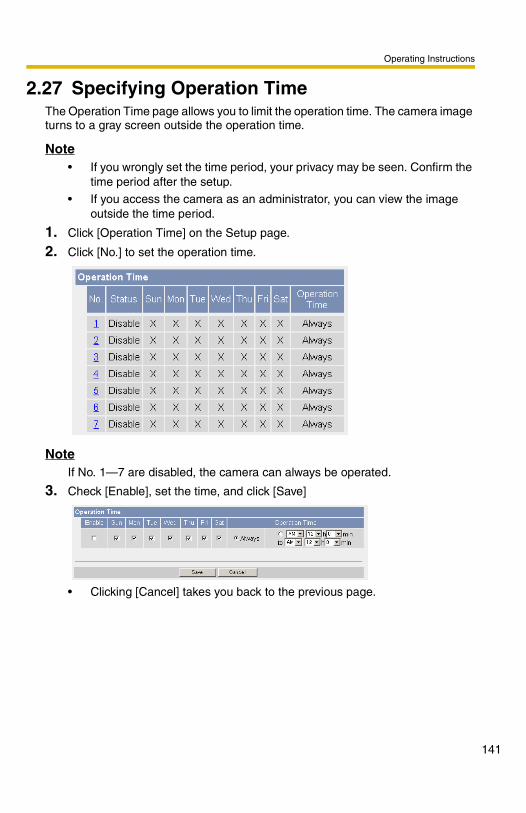
Operating Instructions
2.27 Specifying Operation TimeThe Operation Time page allows you to limit the operation time. The camera image turns to a gray screen outside the operation time.
Note• If you wrongly set the time period, your privacy may be seen. Confirm the
time period after the setup.• If you access the camera as an administrator, you can view the image
outside the time period.
1. Click [Operation Time] on the Setup page.
2. Click [No.] to set the operation time.
NoteIf No. 1—7 are disabled, the camera can always be operated.
3. Check [Enable], set the time, and click [Save]
• Clicking [Cancel] takes you back to the previous page.
141

Operating Instructions
14
4. Click [Save] when finished.
• New settings are saved.• The Operation Time page is displayed.
About Operation TimeIn the operation time settings, the enabled settings take priority over the disabled settings. Therefore, if Monday or Tuesday is disabled in a setting but enabled in other settings, the camera can be operated on both Monday and Tuesday.
Setting Description
Enable • Check the box to enable the setting. Clear the box to disable it.
A day of the week
• Check the box to enable the day. Clear the box to disable it.
Operation Time • Select the [Always] option when you do not specify the time period. If you specify the time period, select the time period option and set the time period.
2

Operating Instructions
2.28 Controlling External Output TerminalThe digital output terminal allows you to control external devices. You can change the initial status of the output signal.
NoteConnect the external devices to the camera.
1. Click [External Output] on the Setup page.
2. Click [Save] when finished.
• Clicking [Cancel] cancels your settings without saving changes.• New settings are saved.• When finished, "Success!" is displayed.
3. Click [Go to External Output Control page].
• The External Output Control page is displayed.
Setting Description
External Device Control Output
• If you check [Open], the internal transistor turns off and the external output terminal gets high impedance (open collector) when the camera powers up. If you check [Short to GND], the internal transistor turns on and is electrically short-circuited to GND pin when the camera powers up. The external output terminal gets low impedance (0 V).
Button name modification
• You can change the output control button names on the operation bar. You can name the button depending on your external devices.
143

Operating Instructions
14
2.29 Changing Indicator DisplayThe Indicator Control page allows you to select Indicator operation. Indicator has three options.• Always on• Turn the indicator on when the camera is accessed.• Always off
1. Click [Indicator Control] on the Setup page.
2. Select indicator option.
• Clicking [Cancel] cancels your settings without saving changes.
Note• See page 14 for indicator display.• Selecting [Never turn indicator on] keeps indicator always off.
3. Click [Save] when finished.
• New settings are saved.• When finished, "Success!" is displayed.
4. Click [Go to Indicator Control page].
• The Indicator Control page is displayed.
4

Operating Instructions
3 Camera Maintenance
3.1 Maintenance page
Maintenance
(1) Status Displays the camera settings and status (see page 146).
(2) Session Status Displays information on access to the camera (see page 146).
(3) Alarm Log Displays alarm logs (see page 147).
(4) Restart Restarts the camera (see page 148).
(5) Update Firmware Updates the camera firmware (see page 149).
(6) Save Settings Creates a configuration file (see page 152).
(7) Load Settings Loads settings from a configuration file (see page 153).
(8) Reset to Factory Default
Resets the camera to its default settings (see page 154).
(1)(2)
(3)
(4)
(5)
(6)(7)(8)
145

Operating Instructions
14
3.1.1 Confirming the StatusThe Status page allows you to check the status of the camera. The status information provides support for troubleshooting.Clicking [Status] displays the following page.
NoteSee Panasonic Network Camera support website at http://panasonic.co.jp/pcc/products/en/netwkcam/ for details about status information.
3.1.2 Confirming Session StatusDisplays client information connecting to camera.Clicking [Session Status] displays the following page.
6

Operating Instructions
3.1.3 Displaying Alarm LogsDisplays up to 50 Alarm Logs in order of time. Old logs will be overwritten by new one.
1. Click [Alarm Log] on Maintenance page.
2. Alarm Logs are displayed.
NoteIf the camera is restarted, all alarm logs are deleted.
Item Description
New Alarm Logs • Displays the number of new alarm logs.
Date • Displays the date and time when the Alarm 1, 2, or Motion Detect were responded.
Sensor Type • Displays the Trigger Setting (Alarm 1, 2, or Motion Detection) on the Trigger page.
Signal Type • Displays the Alarm enable condition on the Trigger page when selected Alarm 1 or 2.
147

Operating Instructions
14
3.1.4 Restarting the CameraThe Restart page can restart the camera. The camera can also be restarted by pressing the RESTART button (see page 160) or by disconnecting the AC adaptor cord from the outlet and reconnecting it again.
NoteWhen the camera restarts, the buffered images will be deleted. The buffered images on the SD memory card are not deleted.
1. Click [Restart] on the Maintenance page.
2. Click [Restart].
• Restarting takes about 1 minute. The Top page is displayed when finished.
8

Operating Instructions
3.1.5 Updating the Camera FirmwareThe Update Firmware page allows you to update the camera firmware. If the new firmware is available, install it into the camera.
Note• Do not turn off the power during firmware update.• All buffered images on the internal memory will be deleted after the
firmware update. The buffered images on the SD memory card are not deleted.
• The firmware version is displayed on the Top page and the Status page.
1. Download the new firmware on the Panasonic Network Camera support website at http://panasonic.co.jp/pcc/products/en/netwkcam/, and save it on your PC.
2. Click [Update Firmware] on the Maintenance page.
3. Click [Update Firmware].
• The camera restarts.
149

Operating Instructions
15
• The Update page is displayed in about 1 minute.
4. Click [Browse...].
• A dialog box is displayed to select the firmware.
5. Select the firmware (including directory information) and click [Open].
• The firmware file name is displayed.
6. Confirm the firmware file name, and click [Update Firmware].
• Clicking [Cancel] takes you back to the Top page without firmware update.• The next message is displayed during update.
• The camera restarts automatically after update.
• The Top page is displayed in about 1 minute.
0

Operating Instructions
7. Confirm that the version number on the Top page is updated.
• If the version number is updated, the firmware update is complete.Updated version
151

Operating Instructions
15
3.1.6 Creating Configuration FileA configuration file can be saved on your PC. You can load the camera settings from the configuration file on the Load Settings page (see page 153).
NoteThe saved image has privacy information. Prevent private information leaks.
1. Click [Save Settings] on the Maintenance page.
2. Click [Save].
3. Click [Save] on the File Download dialog box.
4. Specify the location, and click [Save] on the Save As dialog box.
• The configuration file is saved in the location.
Note• The file extension (.dat) cannot be changed. If you change it, the settings
cannot be loaded.• If you try to update the camera, create a configuration file after updating
the firmware. If there is a firmware version difference between the camera that you create a configuration file from and the camera that you try to load settings to, the settings may not be loaded to the camera.
2

Operating Instructions
3.1.7 Loading Settings from a Configuration FileThe settings can be loaded from a configuration file. If you reset the camera to factory default, the camera can load its settings from the configuration file.
Note• The configuration file has network settings. When the settings are loaded,
the network settings are also loaded as they were saved.
• If you try to update the camera, create a configuration file after updating the firmware. If there is a firmware version difference between the camera that you create a configuration file from and the camera that you try to load settings to, the settings may not be loaded to the camera.
1. Click [Load Settings] on the Maintenance page.
2. Click [Browse...].
3. Select the configuration file on the Choose file dialog box, and click [Open].
• The file name is displayed in the data field.
4. Confirm the file name, and click [Load].
5. Click [Restart].
• The camera restarts, and the Top page is displayed.
153

Operating Instructions
15
3.1.8 Resetting the Camera to Factory DefaultAll camera settings are reset to factory default directly after the Execute button is clicked.
1. Click [Reset to Factory Default] on the Maintenance page.
2. Click [Execute].
• The indicator blinks orange, and then turns off for 10 seconds.• All camera settings (user name, password, IP address, subnet mask etc.)
are reset to factory default.• If the camera is reset to factory default, the network connection mode
changes to [Automatic Setup]. Reconfigure the camera seeing Getting Started.
Note• The internal clock will not be reset, but the time format will return to AM/
PM mode (see page 78). Set it again.• See page 164—page 172 for default settings.• Pressing the FACTORY DEFAULT RESET button resets the camera to the
factory default (see page 161).• All buffered images on the internal memory are deleted when resetting the
camera to factory default. The buffered images on the SD memory card are not deleted.
• The reset operation takes about 1 minute.• Do not turn off the camera during the reset operation.• If the camera is restarted, all alarm logs are deleted.
4

Operating Instructions
3.2 Support page
3.2.1 Seeing Help pageThe Help page displays explanations for each feature about the following 1. to 6. items.Clicking [Help] on the Support page displays the next page.
3.2.2 Seeing Product InformationYou can see product information on the Panasonic Network Camera support website.Clicking [Product Information] on the Support page displays the URL, click it.
NoteIf the camera is not connected to the Internet, the website cannot be displayed.
Support
(1) Help Displays the Help page (see page 155).
(2) Product Information
Displays product information website (see page 155).
(3) Support Information
Displays support information website (see page 156).
(1)
(2)
(3)
155

Operating Instructions
15
3.2.3 Seeing Support InformationYou can see support information on the Panasonic Network Camera support website.Clicking [Support Information] on the Support page displays the URL, click it.
NoteIf the camera is not connected to the Internet, the website cannot be displayed.
6

Operating Instructions
3.3 Using the SD Memory CardThe SD memory card (customer-provided) can store image data and replay them. Follow the instructions below to insert the SD memory card into the camera.
1. Open the cover on the side of the camera.
2. Insert the SD memory card, and push with your finger until it clicks. Or push the card lightly to remove.
Note• Ensure that recording has stopped before removing the SD memory card.
(See page 139) Do not remove the SD memory card, nor restart or turn off the camera while recording images on the card. Doing so can cause a decrease in SD memory card capacity, data corruption or camera malfunction.
• Insert or remove the SD memory card after removing the sunshade.
3. Replace the cover firmly.
Note• Sound cannot be recorded.• Format the SD memory card, before you record the image data. (See
page 138)
Place the card face to the front.
PRO HIGH SPEED
LOCK
157

Operating Instructions
15
3.4 External I/OIf you connect the external devices such as sensors to the External I/O and image buffer/transfer by alarm signal is set, the camera image is transferred by the alarm detection.
Explanation of the External I/O
NoteThe External I/O (Input/Output) is independent. Output terminal is controlled only by External Output Control page on page 143.
Pin Features
G GND pin
1 External Sensor Input 1• Use it by opening or GND short-circuit.
G GND pin
2 External Sensor Input 2• Use it by opening or GND short-circuit.
3 External Device Control Output• You can control it on the External Output page (see page 143).• It is an open collector circuit, and the maximum drawing-in current
is the same as pin 4. Do not exceed the voltage of DC power output terminal (pin 4).
4 DC Power Output Terminal• 10.5—13.5 V DC• Maximum of 100 mA load drive is possible.
8

Operating Instructions
Circuit Diagram Example
CAUTION
• The external I/O is not capable of connecting directly to devices that require large amounts of current. In some case, a custom interface circuit (customer-provided) may have to be used. Serious damage to the camera may result if a device is connected to the external I/O that exceeds its electrical capability (see page 158).
• The low voltage/current circuits and high voltage/current circuits are in the camera circuit. The qualified electrician should do the wiring not by yourself. Incorrect wiring could damage the camera. You could receive the fatal electric shock.
Light
Door Sensor 1 (Alarm 1)
Door Sensor 2 (Alarm 2)
RelayCamera
12 V
234
G
1G
DC10.5 V–13.5 V
159

Operating Instructions
16
3.5 [For BB-HCM331] RESTART ButtonThe camera has a RESTART button on the side.
Pressing the RESTART button restarts the camera.
Note• After removing the sunshade, press the RESTART button.• All buffered images on the internal memory are deleted when restarting
the camera. The buffered images on the SD memory card are not deleted.• Restarting takes 1 minute.
RESTART Button(Press the button with a pointed object.)
0

Operating Instructions
3.6 FACTORY DEFAULT RESET ButtonThe camera has a FACTORY DEFAULT RESET button on the side.
Pressing the FACTORY DEFAULT RESET button resets the camera to factory default. If you lose your user name and password, use this button to reset the camera.• Press the FACTORY DEFAULT RESET button for 1 second when the camera
is on.• The indicator blinks orange, and then turns off for 5 seconds.• Do not turn off the camera until the indicator lights green.
Note• After removing the sunshade, press the FACTORY DEFAULT RESET
button.• The internal clock will not be reset, but the time format will return to AM/
PM mode (see page 78). Set it again.• See page 164—page 173 for default settings.
• All buffered images on the internal memory are deleted when resetting the camera to factory default. The buffered images on the SD memory card are not deleted.
• The reset operation takes about 1 minute.• If the camera is restarted, all alarm logs are deleted.
FACTORY DEFAULT RESET Button(Press the button with a pointed object.)
161

Operating Instructions
16
3.7 Mounting the CameraTwo mounting methods are shown in the following figures: Tripod Mount and Ceiling Mount. See Getting Started for two other methods of mounting. Confirm the top and bottom of the camera when mounting. Ask the authorized dealer for Ceiling Mount.
NoteMounting and cabling instructions described below follow generally accepted guidelines suitable for residential installations. In some areas, commercial and industrial installations are regulated by local or state ordinances. For such installations, contact your local building department or building inspector for more details.
Flexible Stand Mount
Tripod Mount
Stand/Tripod Mounting Hole
Flexible Stand
Screw the threaded mount into the stand/tripodmounting hole.
Turn the grip firmly.
Stand/Tripod Mounting Hole
Tripod
2

Operating Instructions
Ceiling MountNote• Do not mount the camera upside down. The image may be displayed
upside down.
• When mounting, we suggest using the hardware we provide. Mounting in any other manner may cause the camera to fall, causing personal injury or damage to the camera.
• To reduce the load on the mounting hardware, dress the cables neatly and secure with tape.
Make sure the indicator is always in the lower right corner.
Top
Bottom
Caulk aroundflexible standif necessary.
Mount the flexible stand firmly to the ceiling with the three screws (accessories).
Attach the camera screwing the threaded mount into the stand mounting hole.
ScrewStandMounting Hole
Adjust the camera position and secure the flexible stand firmly.
Do not mount the camera on a soft material. The camera may fall and break down.Use appropriate screws suited for the material of the ceiling. Roll up the cables and flexible stand
with the self bonding tape (accessories for BB-HCM331 only) or tape (customer-provided).
Self bonding tape (accessories for BB-HCM331 only) or tape (customer-provided)
Waterproof the rest of the cable (for BB-HCM331 only, see Getting Started).
163

Operating Instructions
16
3.8 Default Setting ListBasic
Items Default Required Note
Network (IPv4)
Connection Mode Automatic Setup
- Automatic Setup/Static/DHCP
Allow Access from the Internet (Automatic Setup only)
No - -
Network Configuration from Setup Program (Static/DHCP only)
Enable - -
Port No. (Static/DHCP only)
80 - 20, 21, 25 and 110 is not available.*2
IP address (Static only)
192.168.0.253
When setting Static
*1
Subnet Mask (Static only)
255.255.255.0
When setting Static
*1
Host Name (DHCP only)
[Blank] When setting DHCP (Not always required)
0—63 characters *4
Default Gateway (Static/DHCP only)
[Blank] When using Gateway
*1
DNS Server 1 DNS Server 2 (Static/DHCP only)
[Blank] When using DNS
*1
Max. Bandwidth Usage (Mbps)
Unlimited - 0.1, 0.2, 0.3, 0.5, 1 or Unlimited
Connection Type Auto Negotiation
- -
4

Operating Instructions
Network (IPv6)
Connection Mode Automatic Setup
- Automatic Setup/Static
Allow Access from the Internet (Automatic Setup only)
No - -
Port No. (Static only)
80 - 20, 21, 25 and 110 is not available.*2
IP address (Static only)
[Blank] When setting Static
*1
Default Gateway (Static only)
[Blank] When using Gateway
*1
DNS Server 1 DNS Server 2
[Blank] When using DNS
*1
Max. Bandwidth Usage (Mbps)
Unlimited - 0.1, 0.2, 0.3, 0.5, 1 or Unlimited
Connection Type Auto Negotiation
- -
IPsec Use No check - -
Encoding strength Standard (AES, 3DES, DES, NULL)
- Standard/High
Transport [Blank] - -
Tunnel [Blank] - -
UPnP Auto Port Forwarding Disable - -
Display Shortcut Icon in My Network Places
Enable - -
Items Default Required Note
165

Operating Instructions
16
DynamicDNS
Viewnetcam.com No check When setting
viewnetcam.com
Viewnetcam.com/User-specified DynamicDNS/
Disable
User-specified DynamicDNS
[Blank] - Viewnetcam.com/User-specified DynamicDNS/
Disable
10 min - At the time of starting/10,
30(min), 1, 3, 6, 12, 24(h)
Date and Time
Time Setting AM/PM - -
Automatic Time Adjustment
No check When using NTP
-
Time Zone GMT 00:00 - -
Adjust Clock for Daylight Saving Time
No check - -
Start Day Mar,Last Sunday,
1 AM
- -
End Day Oct,Last Sunday,
1 AM
- -
Items Default Required Note
6

Operating Instructions
Camera Camera Name NetworkCamera
Required 1—15 characters *6
White Balance Auto - Auto/Fixed Indoor/Fixed Fluorescent (White)/Fixed Fluorescent (Daylight)/Fixed Outdoor/Hold
Pan Range (Minimum) -60 degrees - -60—+60 degrees
(Home Position) 0 degrees - -60—+60 degrees
(Maximum) +60 degrees - -60—+60 degrees
Tilt Range (Minimum) -45 degrees - -45—+20 degrees
(Home Position) 0 degrees - -45—+20 degrees
(Maximum) +20 degrees - -45—+20 degrees
Return to Specified Position (Time)
Do not move - Do not move, 10, 20, 30 (sec), 1, 5, 10, 30 (min), 1 h
(Specified Position) Home Position
- Home Position/Alarm No. 1, 2/registered preset number and preset name
Color Night View Disable - -
Items Default Required Note
167

Operating Instructions
16
Account
Audio Output Enable - -
Volume Standard - Minimum/Standard/Maximum
PC Audio Input Timeout 1 min - 1, 2, 3, 5, 10, 20, 30, 60 (min)
Input Enable - -
Camera Microphone Sensitivity
Standard - Minimum/Standard/Maximum
Mute during Pan/Tilt Enable - -
Items Default Required Note
Security: Administrator
General Authentication
Do not permit access from guest users
- -
User Name [Blank] When setting administrator
6—15 characters *3
Password [Blank] When setting administrator
6—15 characters *3
Retype Password
[Blank] When setting administrator
6—15 characters *3
Items Default Required Note
8

Operating Instructions
Buffer/Transfer
General User User ID List [Blank] - -
User Name [Blank] When setting general user
6—15 characters *3
Password [Blank] When setting general user
6—15 characters *3
Retype Password
[Blank] When setting general user
6—15 characters *3
Limit time of Continuous Motion JPEG
Not permitted - Not permitted, Unlimited, 10, 30 (s), 1, 5, 10, 30, 60 (min)
Refresh Interval
3 s - 3, 5, 10, 30, 60 (s)
Access Level No checks - -
Items Default Required Note
Trigger Status Off - -
Trigger Timer - -
Active Time of Trigger Always - -
Image Setting (Image Resolution)
320 x 240 - 160 x 120, 320 x 240, 640 x 480
Image Quality Standard - Favor Clarity, Standard, Favor Motion, Mobile phone
Image Buffer Frequency
Every 1 s, buffer 1 image.
- 1 image per hour—30 images per second
Transfer Method No Transfer, No Memory Overwrite
- -
Notify - - -
Items Default Required Note
169

Operating Instructions
17
Motion Detection
Threshold to start recording
Third blocks from the left
- -
Sensitivity Center - -
Alarm Log
A setup of operation Disable When selecting Alarm1,
Alarm2 or Motion
Detection in Trigger.
Disable/ Enable(When
there is no new-arrival alarm log:Disable)/Enable(When
there is no new-arrival alarm log:Enable)
Active Time PM 12h 0min AM/PM, 1–12 (h), 0/10/20/30/
40/50 (min)
Time Checked -
Notice setup of an alarm log
[Blank] -
Port No. (SMTP) 25 -
Port No. (POP) 110 -
Subject Alarm Log -
Items Default Required Note
0

Operating Instructions
Advanced
Items Default Required Note
Image Display
Single Camera Image Resolution
320 x 240 - 320 x 240 or 640 x 480
Single Camera Image Quality
Standard - Favor Clarity, Standard or Favor Motion
Single Camera Refresh Interval
Motion - 3, 5, 10, 30, 60 (s) or Motion
Multi-Camera Image Resolution
320 x 240 - 160 x 120 or 320 x 240
Multi-Camera Image Quality
Standard - Favor Clarity, Standard or Favor Motion
Multi-Camera Refresh Interval
Motion When reducing
traffic
3, 5, 10, 30, 60 (s) or Motion
Time stamp setting Disable - Enable/Disable
Language English - English/Japanese/French/German/Italian/Spanish/Simplified Chinese/Russian
Banner Display (Administrator)
Checked - -
(General User) Checked - -
171

Operating Instructions
17
Preset Buttons
Multi-Camera
Multi-Camera [Blank] - -
Display Checked When setting Multi-Camera
-
IP Address or Host Name
[Blank] When setting Multi-Camera
IP address*1 Host name*5 is 1—255 characters.
Port No. [Blank] When setting Multi-Camera
20, 21, 25 and 110 are not available.*2
Camera Name [Blank] When setting Multi-Camera
1—15 characters *7
Operation Time
Operation Time Always - -
External Output
External Device Control Output
Open - Open/Short to GND
Button name modification
Open/Short - -
Indicator Control
Indicator Control Turn indicator on when
camera is on
- -
Items Default Required Note
Preset Buttons
Preset 1 UpperLeft - -
Preset 2 UpperRight - -
Preset 3 LowerLeft - -
Preset 4 LowerRight - -
Items Default Required Note
2

Operating Instructions
*1 In IPv4, set 4 digits (0—255) and 3 periods such as "192.168.0.253". But "0.0.0.0" and "255.255.255.255" are not available.In IPv6, set 8 hexadecimal digits divided with ":". Consecutive 0s can be abbreviated as "::".
*2 Set the number of 1—65535.*3 Enter ASCII characters (see page 183). But [Space], ["], ['], [&], [<], [>] and [:]
are not available.*4 Enter ASCII characters for the host name (see page 183). But [Space], ["], ['],
[&], [<], and [>] are not available.*5 Enter ASCII characters for the host name (see page 183). But [Space], ["], ['],
[#], [&], [%], [=], [+], [?], [<], and [>] are not available.*6 Enter ASCII characters (see page 183) or characters in each language (1—15
characters for a 1-byte character and 1—7 characters for a 2-byte character). But [Space], ["], ['], [&], [<], and [>] are not available.
*7 Enter ASCII characters (see page 183) or characters in each language (1—15 characters for a 1-byte character and 1—7 characters for a 2-byte character). But [Space], ["], ['], [#], [&], [%], [=], [+], [?], [<], and [>] are not available.
173

Operating Instructions
17
3.9 CleaningAfter the camera is turned off by disconnecting the AC plug, clean the camera.
3.9.1 Cleaning the Main UnitIf the lens cover has the sand or the dust, image quality may decrease. After taking away the sand or the dust on it, wipe it with a dry cloth.
Note• Do not use alcohol, polishing powder, cleanser, benzine, thinner, wax,
petroleum products or hot water to wipe the camera. Also avoid glass cleaner, pesticide or hair spray. They may cause change in the shape or color.
• Do not directly touch the lens cover. Your fingerprints can cause the image to be out of focus.
• [For BB-HCM331] Do not directly pour the water with a hose to wash the unit or the lens cover.
4

Operating Instructions
3.10 Setting an IP Address on Your PCYour PC's IP address can be assigned by the following procedures.
1. Display the TCP/IP Properties window.
• The steps are different depending on your OS. The steps are shown below.
• When using Windows XP and Windows 2000, log in as an administrator to access the TCP/IP Properties window.
2. Enter IP address and subnet mask.
3. Click [OK].
• In Windows Me or Windows 98SE, the PC needs to be restarted to enable the settings.
Local IP AddressLocal IP address is the network ID that is not used on the Internet. They are classified into Class A, Class B and Class C, as shown below. Set the IP address in the range of the number specified in the class corresponding to your local network scale.
OS Steps
Windows XP [Start] ( [Settings]) [Control Panel] [Network and Internet Connections] [Network Connections] [Local Area Connection] in use [Properties] Select Internet Protocol [TCP/IP] [Properties] [Use the following IP address]
Windows 2000 [Start] [Settings] [Control Panel] [Network and Dial-up Connections] [Local Area Connection] in use
[Properties] Select Internet Protocol [TCP/IP] [Properties] [Use the following IP address]
Windows Me, Windows 98SE
[Start] [Settings] [Control Panel] [Network] Select [TCP/IP] with adaptor in use [Properties] [IP Address]
[Specify an IP address]
Class Subnet Mask Local IP Address
Class A 255. 0. 0. 0 10. 0. 0. 1 — 10. 255. 255. 254
Class B 255. 255. 0. 0 172. 16. 0. 1 — 172. 31. 255. 254
Class C 255. 255. 255. 0 192. 168. 0. 1 — 192. 168. 0. 254
175

Operating Instructions
17
3.11 Using Setup ProgramThe Setup Program can be used for the following purposes.• Finding the IP address and port number of the camera connected to your
network.• Setting up the camera automatically.• Setting up the camera manually to a Static or a DHCP setting.• Disabling IPsec.• Displaying the Setup page.
Finding the camera1. Insert the Setup CD-ROM into the CD-ROM drive of your PC.
• If the Panasonic Network Camera Setup window does not appear, click "setup.exe" on the Setup CD-ROM.
2. Click [Camera Setup].
• When the following dialog box is displayed, click [Unblock].
Displays version information about this program.
Sets up the camera.Displays the camera manuals. If your PC does not have Adobe® Acrobat® Reader®, install it from the Adobe Reader website.
Installs Network Camera Recorder trial version.Closes the Setup Program.
6

Operating Instructions
• You can find the camera IP address and port number by looking up the MAC address of your camera.
IPv6 Information
Note• If you try to find multiple cameras, each MAC address beside the Ethernet
(LAN) port verifies which camera you are setting up.• See Getting Started for the setup from the MAC address.
Camera Status
Camera List windowDisplays IPv4 or IPv6 information.
Port No.
MAC Address
IP Address
177

Operating Instructions
17
Automatic Setup (Local or Internet Access) or Manual Setup1. Click [Execute] on the Camera List window shown on page 177.
2. Click each button to execute the program.
Note• See Getting Started for the local and Internet access setup.Manual Setup windowSet up each parameter seeing page 53—page 55.• If more than 20 minutes have passed since the camera was turned on, the
camera cannot be set up from the Setup Program. If the camera cannot be set up, restart the camera.
• If "Camera setup completed" is displayed, click [Close] to finish the Manual Setup.
3. Close all Setup windows.
Sets up the camera to view on the LAN. Sets up the Internet access to the camera. Manually sets up the camera. Disables IPsec. If disabled, the button is displayed gray. Displays the Setup page (see page 48).
8

Operating Instructions
3.12 Setting Your PC3.12.1 Setting the Proxy Server Settings on Web Browser
If the proxy server is not used, the settings are not required. If you are using the proxy server, the following settings are required.• To communicate with a camera installed inside a LAN, changing the web
browser settings is recommended.• A firewall of a proxy server in a corporate environment may prevent access to
the camera. Consult your network administrator.
Note• A proxy server is used to protect your network connected to the Internet.• If the camera is accessed via a proxy server, problems may occur. Consult
your network administrator before installing the camera.
• If the camera is accessed via a proxy server, the refresh interval may be slow.
How to Set the Proxy Server Settings1. Start up Internet Explorer. (The example is Internet Explorer 6.0.)
2. Click [Tools] [Internet Options...].
179

Operating Instructions
18
3. Click the [Connections] tab, and click [LAN Settings].
4. See if the Use a proxy server check box is checked or not. If checked, click [Advanced...].
• If not checked, click [Cancel]. Proxy settings are not required.
See if the checkbox is checked or not.If checked, click [Advanced...].
0

Operating Instructions
5. Enter the camera IP address into the Do not use proxy server for addresses beginning with data field. (Example: 192.168.0.253)
6. Click [OK].
NoteWhen accessing the camera via a proxy server, the Talk Button is displayed gray. Talk feature cannot be used.
181
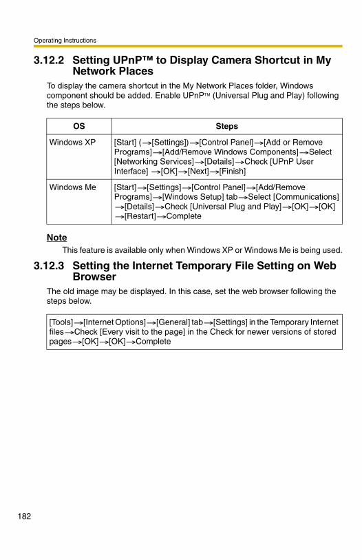
Operating Instructions
18
3.12.2 Setting UPnP™ to Display Camera Shortcut in My Network Places
To display the camera shortcut in the My Network Places folder, Windows component should be added. Enable UPnPTM (Universal Plug and Play) following the steps below.
NoteThis feature is available only when Windows XP or Windows Me is being used.
3.12.3 Setting the Internet Temporary File Setting on Web Browser
The old image may be displayed. In this case, set the web browser following the steps below.
OS Steps
Windows XP [Start] ( [Settings]) [Control Panel] [Add or Remove Programs] [Add/Remove Windows Components] Select [Networking Services] [Details] Check [UPnP User Interface] [OK] [Next] [Finish]
Windows Me [Start] [Settings] [Control Panel] [Add/Remove Programs] [Windows Setup] tab Select [Communications]
[Details] Check [Universal Plug and Play] [OK] [OK] [Restart] Complete
[Tools] [Internet Options] [General] tab [Settings] in the Temporary Internet files Check [Every visit to the page] in the Check for newer versions of stored pages [OK] [OK] Complete
2

Operating Instructions
3.13 ASCII Character Table
(space)!"#$%&'()*+,-./
0123456789:;<=>?
ASCII Character Table@ABCDEFGHIJKLMNO
PQRSTUVWXYZ[\]^_
`abcdefghijkl
mno
pqrstuvwxyz{|}~
183

Operating Instructions
18
3.14 File Size and Number of Buffered ImagesThe following table shows the relationship between the file size of the image and the maximum number of buffered images.
NoteThe following file sizes were shown at the largest value.
Resolution Items Capture Favor Clarity
Standard Favor Motion
Mobile Phone
640 x 480 (pixels)
File Size About 60 KBAbout 50 KB
About 33 KB
About 20 KB
-
Buffered Images
- About 40
About 60 About 100
-
320 x 240 (pixels)
File Size About 30 KBAbout 25 KB
About 16 KB
About 8 KB
About 8 KB
Buffered Images
- About 80
About 125
About 250
About 250
160 x 120 (pixels)
File Size About 10 KB About 7 KB
About 5 KB
About 3 KB
About 3 KB
Buffered Images
- About 290
About 400
About 675
About 675
4

Operating Instructions
3.15 Number of Images on the SD Memory CardThe camera supports the Panasonic SD memory card.
• 1 GB: RP-SDH01GU1A• 512 MB: RP-SDH512U1A• 256 MB: RP-SD256U1A• 128 MB: RP-SD128BU1A• 64 MB: RP-SD064BPPA
NoteThe actual numbers of recordable images may differ from the ones above depending on the kind of SD memory card.
Resolution/Image Quality
1 GB 512 MB 256 MB 128 MB 64 MB
160x
120 (pixels)
Favor Motion
About 300,000
About 157,000
About 78,000
About 39,000
About 19,000
Standard About 180,000
About 94,000
About 47,000
About 23,000
About 11,000
Favor Clarity
About 130,000
About 67,000
About 33,000
About 16,000
About 8,000
320x
240 (pixels)
Favor Motion
About 110,000
About 58,000
About 29,000
About 14,000
About 7,000
Standard About 58,000
About 29,000
About 14,000
About 7,000
About 3,000
Favor Clarity
About 37,000
About 18,000
About 9,000
About 4,000
About 2,000
640x
480 (pixels)
Favor Motion
About 47,000
About 23,000
About 11,000
About 5,000
About 2,000
Standard About 28,000
About 14,000
About 7,000
About 3,000
About 1,000
Favor Clarity
About 18,000
About 9,000
About 4,000
About 2,000
About 1,000
185

Operating Instructions
18
3.16 Specifications
Network Camera
Items Specifications
Zoom 10x digital zoom
Pan/Tilt Angle Pan: -60 ° to +60 °, Tilt: -45 ° to +20 °
Number of Pixels 1/4-inch CCD Sensor 320,000 pixels
Illuminance 3—100,000 lx (0.2—100,000 lx in color night view mode)
White Balance Auto/Manual/Hold
Focus Fixed 0.5 m—Infinity
Caliber Ratio (F No.) F3.5
Horizontal Viewing Angle 53 °
Exposure Auto
Other Specifications
Items Specifications
[For BB-HCM331]Splash Resistant Standard IPX4
Video Compression JPEG (3 Levels)
Video Resolution 640 x 480, 320 x 240 (default), 160 x 120
Buffered Image*1 About 125 frames (320 x 240) with time display(When SD memory card is not inserted.)
Audio Communication 2-way Half Duplex
Audio Bandwidth 300 Hz—3.4 KHz
Audio Play Method Play with ActiveX
Input Encoding Method Encoding with ActiveX
Audio Input Built-in Microphone or External Microphone Input Terminal
Audio Output*2 Audio Line Output Terminal for External Speaker
6

Operating Instructions
Frame rate*3 Max. 12 frames/second (640 x 480)Max. 30 frames/second (320 x 240 or 160 x 120)
Supported Protocols IPv4/IPv6 Dual-Stack• IPv4:
TCP, UDP, IP, HTTP, FTP, SMTP, DHCP, DNS, ARP, ICMP, POP3, NTP, IPsec, UPnP™
• IPv6:TCP, UDP, IP, HTTP, FTP, SMTP, DNS, ICMPv6, POP3, NDP, NTP, IPsec
IPsec Feature ESP Encryption, ESP AuthenticationTransport mode/Tunnel modeIKE (Internet Key Exchange)
IKE (Internet Key Exchange) Pre-Shared Key
Cipher Algorithm DES-CBC, 3DES-CBC, AES-CBC
Message-Digest Algorithm HMAC-MD5, HMAC-SHA-1
Message Transfer Condition Alarm or Timer
Image Transfer Method SMTP, FTP
Interface 10Base-T/100Base-TX Ethernet RJ-45 connector x 1
Indicator Display Power/Network Communication/Camera operation/Ethernet link
External Microphone Input ø 3.5 mm Mini Jack
Audio Output ø 3.5 mm Stereo Mini Jack (But output is mono.)
External I/O External Sensor Input x 2External Sensor Output x 1
SD Memory Card Slot Full Size
Dimension (HWD) About 100 mm x About 100 mm x About 73.5 mm
Weight 310 (Only the unit)
Other Specifications
Items Specifications
187

Operating Instructions
18
Power Supply AC adaptor: Input 100—240 V AC, 50/60 HzOutput 12 V DC, 750 mAConsumption: About 3 W (6 W during pan/tilt scan)
BB-HCM311 Temperature Operation: 0 °C to +40 °CStorage: 0 °C to +50 °C
Humidity Operation: 20 %—80 % (No Condensation)Storage: 20 %—90 % (No Condensation)
BB-HCM331 Temperature Operation: -20 °C to +50 °CStorage: -25 °C to +60 °C
Humidity Operation: 20 %—90 % (No Condensation)Storage: 20 %—90 % (No Condensation)
*1 The maximum number of frames changes depending on the image quality and what object you buffer.
*2 Connect it to an amplifier or an external speaker with a built-in amplifier.*3 Frame rate may slow down depending on the network environment, the PC performance, the
image quality, enabling IPsec, SD memory recording or what object you view.
Other Specifications
Items Specifications
8

Operating Instructions
189
Index

Operating Instructions
19
AAbbreviations 5ActiveX Controls 25Administrator/General Users/Guest Users 90Alarm Image Buffer/Transfer 104Alarm Log 131, 147Alarm Position 34ASCII Character Table 183Audio page 86
BBuffered Image page 43
CCamera Access 20Camera page 81Capture Image Button 30Ceiling Mount 163Cleaning 174Click to Center 29Clicking the right mouse button 33CPU 12, 13
DDate and Time page 78Default Setting List 164Digital zoom feature 3DynamicDNS 73, 76
EExplanation of the External I/O 158External I/O 158External Output page 143
FFACTORY DEFAULT RESET Button 161Flexible Stand Mount 162For IPv4 Connection 12For IPv6 Connection 13
GGeneral User page 92
HHelp page 155Home Position 34How to Use This Documentation 5
IImage Display page 133Indicator Control page 144IPsec 60IPv6 Domain Name Service 22
LListen 38Load Settings page 153Login 91
MMaintenance page 145Mobile Phone 46Motion Detection 115, 128Multi-Camera page 41Multi-Camera Setup page 136
NNetwork (IPv4) page 51Network (IPv6) page 56
OOperating System 12, 13Operation Bar 31Operation Time page 141
PPan/Tilt Range 32, 85Preset position 34Product Information page 155Protocol 12, 13
0

Operating Instructions
RReset to Factory Default page 154RESTART Button 160Restart page 148Rotating the mouse wheel 33
SSave Settings page 152SD memory card 138, 139Security: Administrator page 88Session Status 146Setup page 48Setup Program 176Single Camera page 24Specifications 186Status page 146Support Information page 156Support page 155System Requirements for your PC 12
TTalk 38Timer Image Buffer/Transfer 95Top page 21Trademarks 5Transport mode 63, 126Tripod Mount 162Tunnel mode 66, 127
UUpdate Firmware page 149UPnP page 70
WWeb Browser 12, 13
191

PSQX3754ZB KK0505JT1056 (CE)
2005 Panasonic Communications Co., Ltd. All Rights Reserved.
Copyright:This material is copyrighted by Panasonic Communications Co., Ltd., and may be reproduced for internal use only. All other reproduction, in whole or in part, is prohibited without the written consent of Panasonic Communications Co., Ltd.
The information in this document is subject to change without notice.
Panasonic Communications Co., Ltd.1-62, 4-chome, Minoshima, Hakata-ku, Fukuoka 812-8531, Japan