need assessment and workshop reports - dcsdesignclinicsmsme.org/download/designawareness... ·...
TRANSCRIPT

GRAU BÄR DESIGN
Attention Project Date No. Project Coordinator PHDCC MSME Design Clinic New Delhi 600 017
Micro Optics Cluster Ambala, Haryana.
Friday, April 12, 2013
01042013PHDCC/MSME Page 1 of 146
22-23, Sajan Nagar, Lane No. 2, Indore, M.P. 452 001, India Voice: (+91) 731-2403573 (+91) 731-2401329 [email protected]
Need Assessment and Workshop Reports
Consolidated

GRAU BÄR DESIGN
Attention Project Date No. Project Coordinator PHDCC MSME Design Clinic New Delhi 600 017
Micro Optics Cluster Ambala, Haryana.
Friday, April 12, 2013
01042013PHDCC/MSME Page 2 of 146
22-23, Sajan Nagar, Lane No. 2, Indore, M.P. 452 001, India Voice: (+91) 731-2403573 (+91) 731-2401329 [email protected]
Need Assessment Report
Micro Optics Cluster Ambala, Haryana
April, 2013
By,
Parag K. Vyas
Grau Bär Design, Indore

GRAU BÄR DESIGN
Attention Project Date No. Project Coordinator PHDCC MSME Design Clinic New Delhi 600 017
Micro Optics Cluster Ambala, Haryana.
Friday, April 12, 2013
01042013PHDCC/MSME Page 3 of 146
22-23, Sajan Nagar, Lane No. 2, Indore, M.P. 452 001, India Voice: (+91) 731-2403573 (+91) 731-2401329 [email protected]
Table of Contents Introduction ......................................................................................................... 6
Cluster History and Evolution ............................................................................... 9 Cluster History .......................................................................................................... 10 Evolution .................................................................................................................. 12
Cluster Products ................................................................................................. 15
Microscope lenses Overview .............................................................................. 17 Lens .......................................................................................................................... 18 History of lens ........................................................................................................... 19
Micro Optics (Processes) .................................................................................... 25 Process for Lenses ..................................................................................................... 29 Process for Prism....................................................................................................... 36
Marketing System .............................................................................................. 37
Technology up gradation .................................................................................... 40
R&D ................................................................................................................... 42
Training & Skill Up gradation for Workers/employees ........................................ 44
Logistics & Storage & Packaging ......................................................................... 46
Investigation and Assessment ............................................................................ 48 Work place organization ............................................................................................ 49 Material flow/ Process control .................................................................................. 50 Hygiene .................................................................................................................... 51 Shop floor/Work space .............................................................................................. 52

GRAU BÄR DESIGN
Attention Project Date No. Project Coordinator PHDCC MSME Design Clinic New Delhi 600 017
Micro Optics Cluster Ambala, Haryana.
Friday, April 12, 2013
01042013PHDCC/MSME Page 4 of 146
22-23, Sajan Nagar, Lane No. 2, Indore, M.P. 452 001, India Voice: (+91) 731-2403573 (+91) 731-2401329 [email protected]
Ergonomics ............................................................................................................... 53 Visual/ illumination ................................................................................................... 54 Tools/ fixtures and devices ........................................................................................ 55 Forward and backward linkages................................................................................. 56
Statement of Needs ........................................................................................... 57
Conclusion ......................................................................................................... 59
Annexure ........................................................................................................... 61 List of Manufacturing Units ....................................................................................... 62 Contact Persons ........................................................................................................ 64
Annexure 1 ........................................................................................................ 66 Lens .......................................................................................................................... 66
Annexure 2 ........................................................................................................ 80 Prism ........................................................................................................................ 80
Annexure 3 ........................................................................................................ 89 Optical Microscope ................................................................................................... 89
Workshop Report ........................................................................................ 102
Introduction ..................................................................................................... 103
Remedial Design & other Solutions .................................................................. 106 Ergonomics ............................................................................................................. 106 Workplace illumination ........................................................................................... 108 Glare ....................................................................................................................... 110 Color of the workstation .......................................................................................... 113 Maintaining the tools & machineries ....................................................................... 114 Introduction to the kan-ban system ......................................................................... 119 Precision Working and Workplace Envelope ............................................................ 120 Importance of leveling the machineries ................................................................... 124 Line of sight ............................................................................................................ 126

GRAU BÄR DESIGN
Attention Project Date No. Project Coordinator PHDCC MSME Design Clinic New Delhi 600 017
Micro Optics Cluster Ambala, Haryana.
Friday, April 12, 2013
01042013PHDCC/MSME Page 5 of 146
22-23, Sajan Nagar, Lane No. 2, Indore, M.P. 452 001, India Voice: (+91) 731-2403573 (+91) 731-2401329 [email protected]
Dignity and pride ..................................................................................................... 127 Tool making ............................................................................................................ 127
Annexure ......................................................................................................... 129
Bibliography .................................................................................................... 146

GRAU BÄR DESIGN
Attention Project Date No. Project Coordinator PHDCC MSME Design Clinic New Delhi 600 017
Micro Optics Cluster Ambala, Haryana.
Friday, April 12, 2013
01042013PHDCC/MSME Page 6 of 146
22-23, Sajan Nagar, Lane No. 2, Indore, M.P. 452 001, India Voice: (+91) 731-2403573 (+91) 731-2401329 [email protected]
Introduction

GRAU BÄR DESIGN
Attention Project Date No. Project Coordinator PHDCC MSME Design Clinic New Delhi 600 017
Micro Optics Cluster Ambala, Haryana.
Friday, April 12, 2013
01042013PHDCC/MSME Page 7 of 146
22-23, Sajan Nagar, Lane No. 2, Indore, M.P. 452 001, India Voice: (+91) 731-2403573 (+91) 731-2401329 [email protected]
The Need Assessment Survey for the Micro Optics Cluster at Ambala was conducted during 28th March to 3rd April, 2013 at Ambala Industrial area and its proximity, Haryana. The survey was initiated on behest of PHDCC, New Delhi for MSME and NID Design Clinic Scheme for benefit of micro optics cluster. Primary Objective was to investigate and understand nature of existing needs, which can be addressed by design intervention. Secondary, objective was to understand problems that can be resolved by design or simple mechanical engineering.
Micro, small and medium sized industries were visited to have a heterogeneous group for study. This also allowed for both ends of spectrum, small as well as large, to be taken into consideration for study. Target Group size to be covered in a day, in light of available time, was optimal and adapted well to working in prevailing conditions.
Participants were enthusiastic, attentive and receptive towards the project. They welcomed survey team with openness and freely shared facts as well as feelings. The Cluster was surveyed by visiting individual manufacturing units. Method adapted for getting insights was semi structured; open ended interviews as well as participant observation.
It is pertinent to mention, Ambala Cantonment has one of the largest Indian Army and Indian Air Force presence within the confines of its cantonment area. It is a major market for scientific products for school and colleges. The city is famous for producing great academicians. Therefore has a clear and present potential for Design Clinic scheme projects.
Ambala is a city and a municipal corporation in Ambala district in the state of Haryana, India, located on the border to the state of Punjab. Politically; Ambala has two sub-areas: Ambala Cantonment (Ambala Cantt) and Ambala City, approximately 3 kilometers apart from each other, therefore it is also known as "Twin City". It has a large Indian Army and Indian Air Force presence within the confines of its cantonment area. Ambala separates the Ganges river network from the Indus river

GRAU BÄR DESIGN
Attention Project Date No.Project CoordinatorPHDCCMSME Design ClinicNew Delhi 600 017
Micro Optics Cluster Ambala, Haryana.
Friday, April 12, 2013
01042013PHDCC/MSMEPage 8 of 146
22-23, Sajan Nagar, Lane No. 2, Indore, M.P. 452 001, IndiaVoice: (+91) 731-2403573 (+91) 731-2401329 [email protected]
network and is surrounded by two rivers – Ghaggar and Tangri – to the north and to the south as seen in figure 1. Due to its geographical location, the Ambala district plays an important role in local tourism.
Figure 1 : Map of Ambala

GRAU BÄR DESIGN
Attention Project Date No. Project Coordinator PHDCC MSME Design Clinic New Delhi 600 017
Micro Optics Cluster Ambala, Haryana.
Friday, April 12, 2013
01042013PHDCC/MSME Page 9 of 146
22-23, Sajan Nagar, Lane No. 2, Indore, M.P. 452 001, India Voice: (+91) 731-2403573 (+91) 731-2401329 [email protected]
Cluster History and Evolution
GRAU BÄR DESIGN
Attention Project Date No. Project Coordinator PHDCC MSME Design Clinic New Delhi 600 017
Micro Optics Cluster Ambala, Haryana.
Friday, April 12, 2013
01042013PHDCC/MSME Page 10 of 146
22-23, Sajan Nagar, Lane No. 2, Indore, M.P. 452 001, India Voice: (+91) 731-2403573 (+91) 731-2401329 [email protected]
Cluster History The micro optics cluster started in early sixties when a microscope was brought from Europe by one of the traders and an attempt was made to manufacture these in Ambala. The cluster has therefore, a recent past and history in contrast to other clusters with deep historical as well as traditional roots.
An attempt was made to manufacture the optical as well as mechanical components locally. The cluster in its present form has little history predating these turn of events. It is substantiated by fact that most of tools, technology and working practices are post world war two with very little or no change over a long period of time.
Before that some physics experiment instruments were by being made, inspired by (and/or copying) European, especially British imports. Partly, it was an attempt to make a cheap affordable version for domestic supply. Often a compromise was made on quality for a variety of reasons ranging from cost cutting to unavailability of tools and equipments.
The other activity was making biology (animal effigies and samples, often trophies and full sized animals) samples and section slides for demonstration and studies in laboratories.
To date, most of the micro optics entrepreneurs are only second generation, who have inherited business from family elders. Some are still younger first generations who have subsequently joined making a specific type of lens or a simple to make component.
The cluster is catering largely to itself, making achromatic pair of lenses for use in microscopes. It is so peculiar that they have little application elsewhere. In simple words microscopes require lenses and the lenses manufactured are largely consumed by a variety of microscopes with different magnification ranges (figure 2). Peripheral

GRAU BÄR DESIGN
Attention Project Date No.Project CoordinatorPHDCCMSME Design ClinicNew Delhi 600 017
Micro Optics Cluster Ambala, Haryana.
Friday, April 12, 2013
01042013PHDCC/MSMEPage 11 of 146
22-23, Sajan Nagar, Lane No. 2, Indore, M.P. 452 001, IndiaVoice: (+91) 731-2403573 (+91) 731-2401329 [email protected]
products are prisms for periscopes and binoculars for military and academic applications.
Figure 2. Structure of cluster.
•Specific & Local Market
•Dependent on each other for survival
•Limited Products
•Micro Optics Cluster
Micro Optical Components
Lenses/ Achromatic
Pairs/ Prisms
Mechanical Components
Microscopes/Periscopes

GRAU BÄR DESIGN
Attention Project Date No. Project Coordinator PHDCC MSME Design Clinic New Delhi 600 017
Micro Optics Cluster Ambala, Haryana.
Friday, April 12, 2013
01042013PHDCC/MSME Page 12 of 146
22-23, Sajan Nagar, Lane No. 2, Indore, M.P. 452 001, India Voice: (+91) 731-2403573 (+91) 731-2401329 [email protected]
Evolution Optics began with the development of lenses by the ancient Egyptians and Mesopotamians, followed by theories on light and vision developed by ancient Greek and Indian philosophers, and the development of geometrical optics in the Greco-Roman world. The word optics is derived from the Greek term τα ὀπτικά which refers to matters of vision. Optics was significantly reformed by the developments in the medieval Islamic world, such as the beginnings of physical and physiological optics, and then significantly advanced in early modern Europe, where diffractive optics began. These earlier studies on optics are now known as "classical optics". The term "modern optics" refers to areas of optical research that largely developed in the 20th century, such as wave optics and quantum optics.
The earliest known lenses were made from polished crystal, often quartz, and have been dated as early as 700 BC for Assyrian lenses such as the Layard / Nimrud lens. There are many similar lenses from ancient Egypt, Greece and Babylon. The ancient Romans and Greeks filled glass spheres with water to make lenses. However, glass lenses were not thought of until the Middle Ages.
Some lenses fixed in ancient Egyptian statues are much older than those mentioned above. There is some doubt as to whether or not they qualify as lenses, but they are undoubtedly glass and served at least ornamental purposes. The statues appear to be anatomically correct schematic eyes.
In ancient India, the philosophical schools of Samkhya and Vaisheshika, from around the 6th–5th century BC, developed theories on light. According to the Samkhya school, light is one of the five fundamental "subtle" elements (tanmatra) out of which emerge the gross elements.
In contrast, the Vaisheshika school gives an atomic theory of the physical world on the non-atomic ground of ether, space and time. The basic atoms are those of earth (prthivı), water (apas), fire (tejas), and air (vayu), that should not be confused with the ordinary meaning of these terms. These atoms are taken to form binary molecules
GRAU BÄR DESIGN
Attention Project Date No. Project Coordinator PHDCC MSME Design Clinic New Delhi 600 017
Micro Optics Cluster Ambala, Haryana.
Friday, April 12, 2013
01042013PHDCC/MSME Page 13 of 146
22-23, Sajan Nagar, Lane No. 2, Indore, M.P. 452 001, India Voice: (+91) 731-2403573 (+91) 731-2401329 [email protected]
that combine further to form larger molecules. Motion is defined in terms of the movement of the physical atoms. Light rays are taken to be a stream of high velocity of tejas (fire) atoms. The particles of light can exhibit different characteristics depending on the speed and the arrangements of the tejas atoms. Around the first century BC, the Vishnu Purana refers to sunlight as "the seven rays of the sun".
In the fifth century BC, Empedocles postulated that everything was composed of four elements; fire, air, earth and water. He believed that Aphrodite made the human eye out of the four elements and that she lit the fire in the eye which shone out from the eye making sight possible. If this were true, then one could see during the night just as well as during the day, so Empedocles postulated an interaction between rays from the eyes and rays from a source such as the sun.
In his Optics Greek mathematician Euclid observed that "things seen under a greater angle appear greater, and those under a lesser angle less, while those under equal angles appear equal". In the 36 propositions that follow, Euclid relates the apparent size of an object to its distance from the eye and investigates the apparent shapes of cylinders and cones when viewed from different angles. Pappus believed these results to be important in astronomy and included Euclid's Optics, along with his Phenomena, in the Little Astronomy, a compendium of smaller works to be studied before the Syntaxes (Almagest) of Ptolemy.
Despite being similar to later particle theories of light, Lucretius's views were not generally accepted and light was still theorized as emanating from the eye.
In his Catoptrica, Hero of Alexandria showed by a geometrical method that the actual path taken by a ray of light reflected from a plane mirror is shorter than any other reflected path that might be drawn between the source and point of observation.
In the second century Claudius Ptolemy, an Alexandrian Greek or Hellenized Egyptian, undertook studies of reflection and refraction. He measured the angles of refraction between air, water, and glass, and his published results indicate that he
GRAU BÄR DESIGN
Attention Project Date No. Project Coordinator PHDCC MSME Design Clinic New Delhi 600 017
Micro Optics Cluster Ambala, Haryana.
Friday, April 12, 2013
01042013PHDCC/MSME Page 14 of 146
22-23, Sajan Nagar, Lane No. 2, Indore, M.P. 452 001, India Voice: (+91) 731-2403573 (+91) 731-2401329 [email protected]
adjusted his measurements to fit his (incorrect) assumption that the angle of refraction is proportional to the angle of incidence.
The Indian Buddhists, such as Dignāga in the 5th century and Dharmakirti in the 7th century, developed a type of atomism that is a philosophy about reality being composed of atomic entities that are momentary flashes of light or energy. They viewed light as being an atomic entity equivalent to energy, similar to the modern concept of photons, though they also viewed all matter as being composed of these light/energy particles.

GRAU BÄR DESIGN
Attention Project Date No. Project Coordinator PHDCC MSME Design Clinic New Delhi 600 017
Micro Optics Cluster Ambala, Haryana.
Friday, April 12, 2013
01042013PHDCC/MSME Page 15 of 146
22-23, Sajan Nagar, Lane No. 2, Indore, M.P. 452 001, India Voice: (+91) 731-2403573 (+91) 731-2401329 [email protected]
Cluster Products
GRAU BÄR DESIGN
Attention Project Date No. Project Coordinator PHDCC MSME Design Clinic New Delhi 600 017
Micro Optics Cluster Ambala, Haryana.
Friday, April 12, 2013
01042013PHDCC/MSME Page 16 of 146
22-23, Sajan Nagar, Lane No. 2, Indore, M.P. 452 001, India Voice: (+91) 731-2403573 (+91) 731-2401329 [email protected]
Major products of the cluster are:
• Optic Lenses • Prisms • Microscopes • Periscopes • Binoculars
Note : More information about optic lenses, prisms & microscope can be found in annexure 1, 2 & 3.

GRAU BÄR DESIGN
Attention Project Date No. Project Coordinator PHDCC MSME Design Clinic New Delhi 600 017
Micro Optics Cluster Ambala, Haryana.
Friday, April 12, 2013
01042013PHDCC/MSME Page 17 of 146
22-23, Sajan Nagar, Lane No. 2, Indore, M.P. 452 001, India Voice: (+91) 731-2403573 (+91) 731-2401329 [email protected]
Microscope lenses Overview
GRAU BÄR DESIGN
Attention Project Date No. Project Coordinator PHDCC MSME Design Clinic New Delhi 600 017
Micro Optics Cluster Ambala, Haryana.
Friday, April 12, 2013
01042013PHDCC/MSME Page 18 of 146
22-23, Sajan Nagar, Lane No. 2, Indore, M.P. 452 001, India Voice: (+91) 731-2403573 (+91) 731-2401329 [email protected]
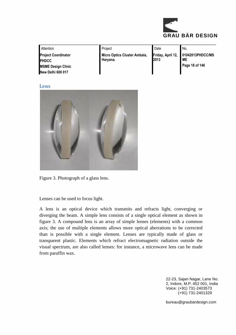
Lens
Figure 3. Photograph of a glass lens.
Lenses can be used to focus light.
A lens is an optical device which transmits and refracts light, converging or diverging the beam. A simple lens consists of a single optical element as shown in figure 3. A compound lens is an array of simple lenses (elements) with a common axis; the use of multiple elements allows more optical aberrations to be corrected than is possible with a single element. Lenses are typically made of glass or transparent plastic. Elements which refract electromagnetic radiation outside the visual spectrum, are also called lenses: for instance, a microwave lens can be made from paraffin wax.

GRAU BÄR DESIGN
Attention Project Date No. Project Coordinator PHDCC MSME Design Clinic New Delhi 600 017
Micro Optics Cluster Ambala, Haryana.
Friday, April 12, 2013
01042013PHDCC/MSME Page 19 of 146
22-23, Sajan Nagar, Lane No. 2, Indore, M.P. 452 001, India Voice: (+91) 731-2403573 (+91) 731-2401329 [email protected]
History of lens The word lens comes from the Latin name of the lentil, because a double-convex lens is lentil-shaped. The genus of the lentil plant is Lens, and the most commonly eaten species is Lens culinaris. The lentil plant also gives its name to a geometric figure.
The oldest lens artifact is the Nimrud lens, dating back 2700 years to ancient Assyria. David Brewster proposed that it may have been used as a magnifying glass, or as a burning-glass to start fires by concentrating sunlight. Another early reference to magnification dates back to ancient Egyptian hieroglyphs in the 8th century BC, which depict "simple glass meniscal lenses".
Figure 4. Depicts how a ray of light gets converged when passes through a biconvex lens.
The earliest written records of lenses date to Ancient Greece, with Aristophanes' play The Clouds (424 BC) mentioning a burning-glass (a biconvex lens used to focus the sun's rays to produce fire as shown in figure 4). Some scholars argue that the

GRAU BÄR DESIGN
Attention Project Date No. Project Coordinator PHDCC MSME Design Clinic New Delhi 600 017
Micro Optics Cluster Ambala, Haryana.
Friday, April 12, 2013
01042013PHDCC/MSME Page 20 of 146
22-23, Sajan Nagar, Lane No. 2, Indore, M.P. 452 001, India Voice: (+91) 731-2403573 (+91) 731-2401329 [email protected]
archeological evidence indicates that there was widespread use of lenses in antiquity, spanning several millennia. Such lenses were used by artisans for fine work, and for authenticating seal impressions. The writings of Pliny the Elder (23–79) show that burning-glasses were known to the Roman Empire, and mentions what is arguably the earliest written reference to a corrective lens: Nero was said to watch the gladiatorial games using an emerald (presumably concave to correct for nearsightedness, though the reference is vague). Both Pliny and Seneca the Younger (3 BC–65) described the magnifying effect of a glass globe filled with water.
Excavations at the Viking harbour town of Fröjel, Gotland, Sweden discovered in 1999 the rock crystal Visby lenses, produced by turning on pole lathes at Fröjel in the 11th to 12th century, with an imaging quality comparable to that of 1950s aspheric lenses as shown in figure 5. The Viking lenses were capable of concentrating enough sunlight to ignite fires.
Figure 5. Viking lenses and an illustration showing how light converges.
Between the 11th and 13th century "reading stones" were invented as shown in figure 6. Often used by monks to assist in illuminating manuscripts, these were primitive plano-convex lenses initially made by cutting a glass sphere in half. As the stones were experimented with, it was slowly understood that shallower lenses magnified more effectively.

GRAU BÄR DESIGN
Attention Project Date No. Project Coordinator PHDCC MSME Design Clinic New Delhi 600 017
Micro Optics Cluster Ambala, Haryana.
Friday, April 12, 2013
01042013PHDCC/MSME Page 21 of 146
22-23, Sajan Nagar, Lane No. 2, Indore, M.P. 452 001, India Voice: (+91) 731-2403573 (+91) 731-2401329 [email protected]
Figure 6. Example of reading stone, being used.
Figure 7. plano-convex lens.
GRAU BÄR DESIGN
Attention Project Date No. Project Coordinator PHDCC MSME Design Clinic New Delhi 600 017
Micro Optics Cluster Ambala, Haryana.
Friday, April 12, 2013
01042013PHDCC/MSME Page 22 of 146
22-23, Sajan Nagar, Lane No. 2, Indore, M.P. 452 001, India Voice: (+91) 731-2403573 (+91) 731-2401329 [email protected]
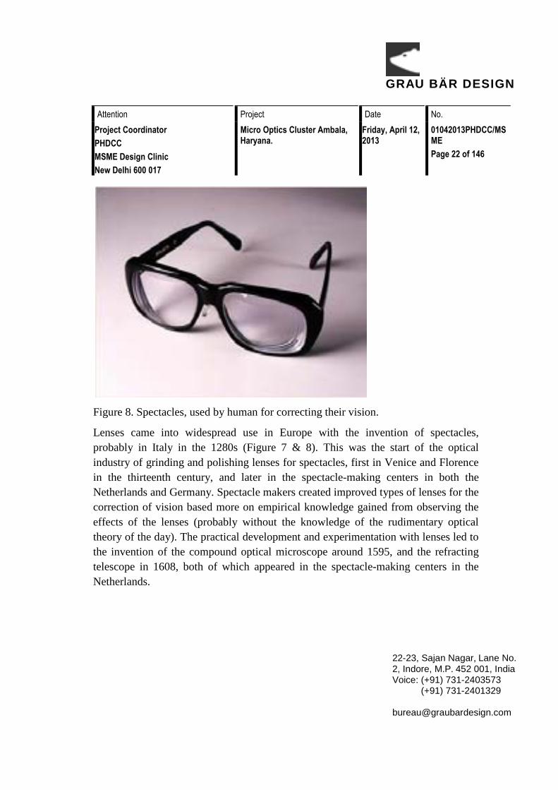
Figure 8. Spectacles, used by human for correcting their vision.
Lenses came into widespread use in Europe with the invention of spectacles, probably in Italy in the 1280s (Figure 7 & 8). This was the start of the optical industry of grinding and polishing lenses for spectacles, first in Venice and Florence in the thirteenth century, and later in the spectacle-making centers in both the Netherlands and Germany. Spectacle makers created improved types of lenses for the correction of vision based more on empirical knowledge gained from observing the effects of the lenses (probably without the knowledge of the rudimentary optical theory of the day). The practical development and experimentation with lenses led to the invention of the compound optical microscope around 1595, and the refracting telescope in 1608, both of which appeared in the spectacle-making centers in the Netherlands.

GRAU BÄR DESIGN
Attention Project Date No. Project Coordinator PHDCC MSME Design Clinic New Delhi 600 017
Micro Optics Cluster Ambala, Haryana.
Friday, April 12, 2013
01042013PHDCC/MSME Page 23 of 146
22-23, Sajan Nagar, Lane No. 2, Indore, M.P. 452 001, India Voice: (+91) 731-2403573 (+91) 731-2401329 [email protected]
Figure 9. Examples of compound optical microscope and refracting telescope.
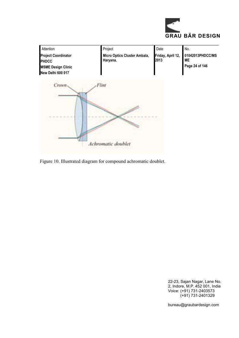
With the invention of the telescope and microscope there was a great deal of experimentation with lens shapes in the 17th and early 18th centuries trying to correct chromatic errors seen in lenses as shown in figure 9 and figure 10 depicting the function of the lense. Opticians tried to construct lenses of varying forms of curvature, wrongly assuming errors arose from defects in the spherical figure of their surfaces. Optical theory on refraction and experimentation was showing no single-element lens could bring all colors to a focus. This led to the invention of the compound achromatic lens by Chester Moore Hall in England in 1733, an invention also claimed by fellow Englishman John Dollond in a 1758 patent.
GRAU BÄR DESIGN
Attention Project Date No.Project CoordinatorPHDCCMSME Design ClinicNew Delhi 600 017
Micro Optics Cluster Ambala, Haryana.
Friday, April 12, 2013
01042013PHDCC/MSMEPage 24 of 146
22-23, Sajan Nagar, Lane No. 2, Indore, M.P. 452 001, IndiaVoice: (+91) 731-2403573 (+91) 731-2401329 [email protected]
Figure 10. Illustrated diagram for compound achromatic doublet.

GRAU BÄR DESIGN
Attention Project Date No. Project Coordinator PHDCC MSME Design Clinic New Delhi 600 017
Micro Optics Cluster Ambala, Haryana.
Friday, April 12, 2013
01042013PHDCC/MSME Page 25 of 146
22-23, Sajan Nagar, Lane No. 2, Indore, M.P. 452 001, India Voice: (+91) 731-2403573 (+91) 731-2401329 [email protected]
Micro Optics (Processes)

GRAU BÄR DESIGN
Attention Project Date No. Project Coordinator PHDCC MSME Design Clinic New Delhi 600 017
Micro Optics Cluster Ambala, Haryana.
Friday, April 12, 2013
01042013PHDCC/MSME Page 26 of 146
22-23, Sajan Nagar, Lane No. 2, Indore, M.P. 452 001, India Voice: (+91) 731-2403573 (+91) 731-2401329 [email protected]
Optical instruments manufactured in Ambala require two types of glass optics. First are lenses, both convex and concave, second prisms and its variations. Overall there are two types of units that complement each other, one polishes and makes objectives and achromatic pairs and or prisms. The other makes the body and mechanical assembly of microscopes, binoculars, periscopes, or other such optical instruments. Both works are highly specialized and require skill as well as a dedicated setup. Even for those units having all facilities under one roof, these two are internally done by separate experts with domain specific skill and experience. This cluster has a unique way of carrying out things, that may appear unorganized from outside, but overall functional structure (of the cluster) can easily be understood by flow diagram below.

GRAU BÄR DESIGN
Attention Project Date No.Project CoordinatorPHDCCMSME Design ClinicNew Delhi 600 017
Micro Optics Cluster Ambala, Haryana.
Friday, April 12, 2013
01042013PHDCC/MSMEPage 27 of 146
22-23, Sajan Nagar, Lane No. 2, Indore, M.P. 452 001, IndiaVoice: (+91) 731-2403573 (+91) 731-2401329 [email protected]
Raw Material Procurement
Assign job to labour
Slitting Glass Block
Stitching on window glass with shellac
Trepanning
Curve Generation
Melting
Grinding
Blocking
Block Smoothing
Polishing
cleaning
Inspection
Edging Girlding
Cementing of Achromatic pair with centering microscope
Finished Product

GRAU BÄR DESIGN
Attention Project Date No.Project CoordinatorPHDCCMSME Design ClinicNew Delhi 600 017
Micro Optics Cluster Ambala, Haryana.
Friday, April 12, 2013
01042013PHDCC/MSMEPage 28 of 146
22-23, Sajan Nagar, Lane No. 2, Indore, M.P. 452 001, IndiaVoice: (+91) 731-2403573 (+91) 731-2401329 [email protected]
Labour IntensiveSlitting Glass Block
Stitching on Window ShellacTrepanning
Curve GenerationMeltingGrindingBlocking
Block SmoothingPolishingCleaning
InspectionEdging Girdling
Cementing of Achromatic pair with centering microscope
High Skill Process Trepanning
Curve Generation Grinding
Block Smoothing Polishing Cleaning
Inspection Cementing of Achromatic pair
with centering microscope
Low Skill Process Slitting Glass Block
Stitching on Window Shellac Melting Blocking
Edging Girdling
Machine Intensive Process Slitting Glass Block
Trepanning Curve Generation
Grinding Block Smoothing
Polishing

GRAU BÄR DESIGN
Attention Project Date No. Project Coordinator PHDCC MSME Design Clinic New Delhi 600 017
Micro Optics Cluster Ambala, Haryana.
Friday, April 12, 2013
01042013PHDCC/MSME Page 29 of 146
22-23, Sajan Nagar, Lane No. 2, Indore, M.P. 452 001, India Voice: (+91) 731-2403573 (+91) 731-2401329 [email protected]
Process for Lenses For benefit of one and all, the process is documented photographically to serve as a reference. It is described in brief, as follows.
1. Slitting Glass Block Raw material arrives in form of glass slabs, as per the specification. These slabs need slitting to get a wafer of a specific thickness for subsequent processing as shown in figure 11 & 12.
Figure 11 & 12. Glass slab and slitting process.
2. Stitching on window glass with shellac Wafer thin glass is difficult to hold and handle, moreover it may break during process owing to extreme thinness and fragile nature. To make it easy to handle it is stitched onto another base plate of common window glass as shown in figure 13 & 14. This makes it easy to hold as well as avoids inadvertent breaking during trepanning.
GRAU BÄR DESIGN
Attention Project Date No. Project Coordinator PHDCC MSME Design Clinic New Delhi 600 017
Micro Optics Cluster Ambala, Haryana.
Friday, April 12, 2013
01042013PHDCC/MSME Page 30 of 146
22-23, Sajan Nagar, Lane No. 2, Indore, M.P. 452 001, India Voice: (+91) 731-2403573 (+91) 731-2401329 [email protected]
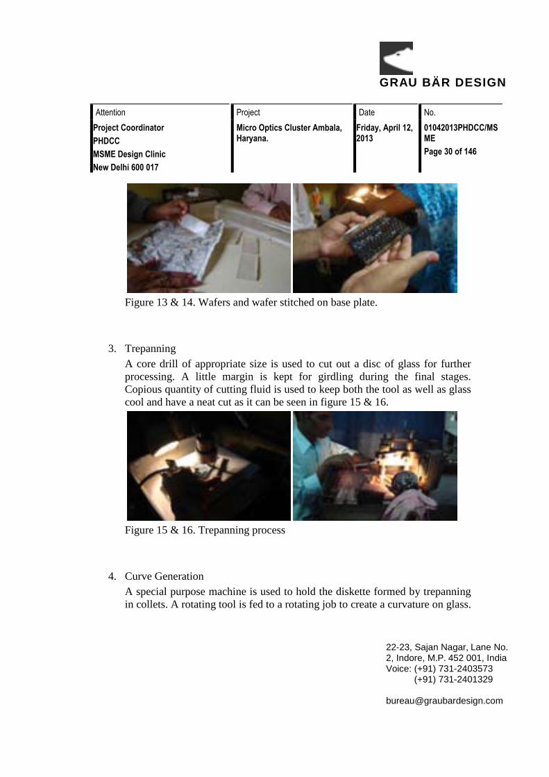
Figure 13 & 14. Wafers and wafer stitched on base plate.
3. Trepanning A core drill of appropriate size is used to cut out a disc of glass for further processing. A little margin is kept for girdling during the final stages. Copious quantity of cutting fluid is used to keep both the tool as well as glass cool and have a neat cut as it can be seen in figure 15 & 16.
Figure 15 & 16. Trepanning process
4. Curve Generation A special purpose machine is used to hold the diskette formed by trepanning in collets. A rotating tool is fed to a rotating job to create a curvature on glass.

GRAU BÄR DESIGN
Attention Project Date No. Project Coordinator PHDCC MSME Design Clinic New Delhi 600 017
Micro Optics Cluster Ambala, Haryana.
Friday, April 12, 2013
01042013PHDCC/MSME Page 31 of 146
22-23, Sajan Nagar, Lane No. 2, Indore, M.P. 452 001, India Voice: (+91) 731-2403573 (+91) 731-2401329 [email protected]
According to settings this can be convex or concave curvature as seen in figure 17 & 18.
Figure 17 & 18. Machine used for curve generation and curve being tested.
5. Melting (Pitch) Owing to small size of curved glass it becomes difficult to grip and handle during grinding. To make it easy to grip, a small blob of pitch is attached to the non grinding side as seen in figure 19 & 20. This makes the grip firm job becomes easy.
Figure 19 & 20. Lenses with small bob of pitch attached.
6. Grinding (2 ½ number emery & 303)

GRAU BÄR DESIGN
Attention Project Date No. Project Coordinator PHDCC MSME Design Clinic New Delhi 600 017
Micro Optics Cluster Ambala, Haryana.
Friday, April 12, 2013
01042013PHDCC/MSME Page 32 of 146
22-23, Sajan Nagar, Lane No. 2, Indore, M.P. 452 001, India Voice: (+91) 731-2403573 (+91) 731-2401329 [email protected]
The lenses go through a grinding process of rough to medium grit size in two stages one after the other. The process is same for both convex and concave lenses as shown in figure 21 & 22. Only significant difference is tool profile, which is reverse of the profile being ground.
Figure 21 & 22. Lenses being grinded through 2½ number and 300 emry
7. Blocking Ground lenses are placed on a specially contoured jig to facilitate blocking operation. A smear of petroleum jelly is used to gently hold during blocking as shown in figure 23 & 24. The same facilitates release after the block is cooled by pouring water over it.
Figure 23 & 24. Petroleum jelly heated and used to set lenses in a jig.
8. Block Smoothing
GRAU BÄR DESIGN
Attention Project Date No. Project Coordinator PHDCC MSME Design Clinic New Delhi 600 017
Micro Optics Cluster Ambala, Haryana.
Friday, April 12, 2013
01042013PHDCC/MSME Page 33 of 146
22-23, Sajan Nagar, Lane No. 2, Indore, M.P. 452 001, India Voice: (+91) 731-2403573 (+91) 731-2401329 [email protected]
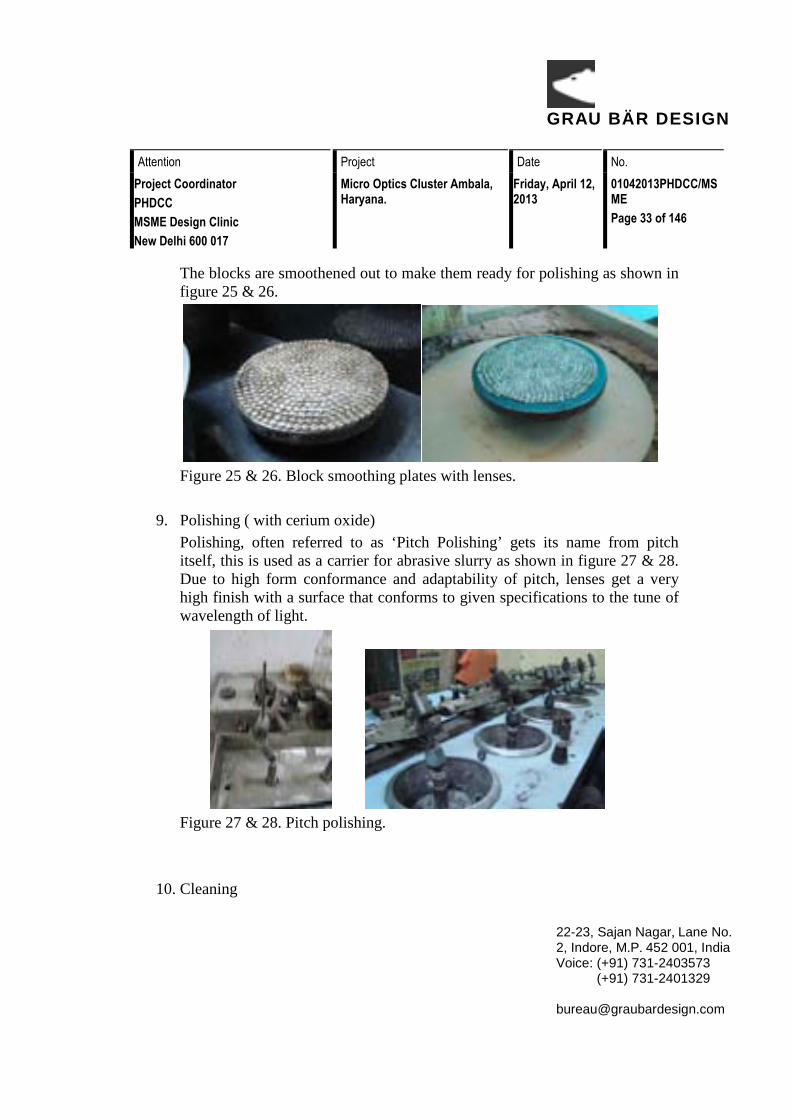
The blocks are smoothened out to make them ready for polishing as shown in figure 25 & 26.
Figure 25 & 26. Block smoothing plates with lenses.
9. Polishing ( with cerium oxide) Polishing, often referred to as ‘Pitch Polishing’ gets its name from pitch itself, this is used as a carrier for abrasive slurry as shown in figure 27 & 28. Due to high form conformance and adaptability of pitch, lenses get a very high finish with a surface that conforms to given specifications to the tune of wavelength of light.
Figure 27 & 28. Pitch polishing.
10. Cleaning

GRAU BÄR DESIGN
Attention Project Date No. Project Coordinator PHDCC MSME Design Clinic New Delhi 600 017
Micro Optics Cluster Ambala, Haryana.
Friday, April 12, 2013
01042013PHDCC/MSME Page 34 of 146
22-23, Sajan Nagar, Lane No. 2, Indore, M.P. 452 001, India Voice: (+91) 731-2403573 (+91) 731-2401329 [email protected]
The polished lenses are cleaned in nitro cellulose thinner or a weak sulfuric acid to clear residual pitch or slurry as shown in figure 29 & 30.
Figure 29 & 30. Cleaning process of lenses.
11. Inspection Ready goods are inspected with a master lens and rejected pieces are sent for regrinding/ polishing after which they can be reused as shown in figure 31 & 32.
Figure 31 & 32. Inspection of lenses with high precision tools.
12. Edging/ Girdling

GRAU BÄR DESIGN
Attention Project Date No. Project Coordinator PHDCC MSME Design Clinic New Delhi 600 017
Micro Optics Cluster Ambala, Haryana.
Friday, April 12, 2013
01042013PHDCC/MSME Page 35 of 146
22-23, Sajan Nagar, Lane No. 2, Indore, M.P. 452 001, India Voice: (+91) 731-2403573 (+91) 731-2401329 [email protected]
The lenses are put on a girdling machine and a firm diameter is polished facilitating a good fit in a mechanical components of an instrument as shown in figure 33 & 34.
Figure 33 & 34. Girdling process.
13. Cementing of Achromatic pair with centering microscope An achromatic pair is matched individually and cemented using a special glue to fix them firmly and the unit is ready for fitting as seen in figure 33 & 34.
Figure 33 & 34. Pair of lenses fitted in shell.

GRAU BÄR DESIGN
Attention Project Date No. Project Coordinator PHDCC MSME Design Clinic New Delhi 600 017
Micro Optics Cluster Ambala, Haryana.
Friday, April 12, 2013
01042013PHDCC/MSME Page 36 of 146
22-23, Sajan Nagar, Lane No. 2, Indore, M.P. 452 001, India Voice: (+91) 731-2403573 (+91) 731-2401329 [email protected]
Process for Prism The process for prisms is similar to lens grinding; only significant difference is use of a flat lap in place of a specially profiled tool. A flat lap gives an optically flat surface to the facet of the prism being polished. Use of slurry and abrasives is same for both lenses as well as prisms.
1. Slitting Glass Block 2. Sizing 3. Blocking 4. Block Smoothing 5. Grinding (2 ½ number emery & 300) 6. Polishing 7. Cleaning 8. Inspection 9. Edging 10. Cementing with centering microscope

GRAU BÄR DESIGN
Attention Project Date No. Project Coordinator PHDCC MSME Design Clinic New Delhi 600 017
Micro Optics Cluster Ambala, Haryana.
Friday, April 12, 2013
01042013PHDCC/MSME Page 37 of 146
22-23, Sajan Nagar, Lane No. 2, Indore, M.P. 452 001, India Voice: (+91) 731-2403573 (+91) 731-2401329 [email protected]
Marketing System

GRAU BÄR DESIGN
Attention Project Date No. Project Coordinator PHDCC MSME Design Clinic New Delhi 600 017
Micro Optics Cluster Ambala, Haryana.
Friday, April 12, 2013
01042013PHDCC/MSME Page 38 of 146
22-23, Sajan Nagar, Lane No. 2, Indore, M.P. 452 001, India Voice: (+91) 731-2403573 (+91) 731-2401329 [email protected]
Market is dealing with few issues, first it is largely supplying locally. Micro optics is made and the end users are in Ambala, which is good as well as bad. (Use of the word micro optic pertains to lenses in very small sizes for objectives and eye pieces for microscopes.)
On positive side, one need not look far and away for a market. On the flipside, if one is affected adversely, the other will also be affected in a similar manner. This becomes very severe. It was revealed during one of informal interviews that if lens polishing goes down, it will take the whole microscope sector down with it.
There is another severe problem the market faces. It is the raw material supply for small buyer. The Chinese material (glass) though cheap, is not available to the end user at a viable price point. It is general complaints that the middleman reaps good profit while the one who puts in maximum effort, physically, does not. The same applies to abrasive slurries and other cutting tools.
A simple solution to problem could be formation of a group to buy in bulk and share material, but this in a close knit (also read, tangled) business community is not plausible. Distrust and competition are the major cause preventing people from such simple solutions. They are ready to buy, and buying from a retailer at a high price, but not ready to cooperate with each other in same trade for the fear of loss of business.
• Local manufacturing and supply (Close loop demand/supply) • Basic raw material glass (imported from China or Germany
leading to one of the two uncertainty of supply and/or high cost ) • Individual material procurement is small • Low material consumption, effort intensive • Demand specific (and relevant to one geographic location) • Distrust, Competition, Secrecy (opposites are needed trust,
cooperation and openness) • Lack of a self regulatory body/practices

GRAU BÄR DESIGN
Attention Project Date No.Project CoordinatorPHDCCMSME Design ClinicNew Delhi 600 017
Micro Optics Cluster Ambala, Haryana.
Friday, April 12, 2013
01042013PHDCC/MSMEPage 39 of 146
22-23, Sajan Nagar, Lane No. 2, Indore, M.P. 452 001, IndiaVoice: (+91) 731-2403573 (+91) 731-2401329 [email protected]
The market is very peculiar and unique but presents good opportunity for design clinic intervention for making a meaningful change.
A flow diagram can be seen for Marketing classification.

GRAU BÄR DESIGN
Attention Project Date No. Project Coordinator PHDCC MSME Design Clinic New Delhi 600 017
Micro Optics Cluster Ambala, Haryana.
Friday, April 12, 2013
01042013PHDCC/MSME Page 40 of 146
22-23, Sajan Nagar, Lane No. 2, Indore, M.P. 452 001, India Voice: (+91) 731-2403573 (+91) 731-2401329 [email protected]
Technology up gradation

GRAU BÄR DESIGN
Attention Project Date No. Project Coordinator PHDCC MSME Design Clinic New Delhi 600 017
Micro Optics Cluster Ambala, Haryana.
Friday, April 12, 2013
01042013PHDCC/MSME Page 41 of 146
22-23, Sajan Nagar, Lane No. 2, Indore, M.P. 452 001, India Voice: (+91) 731-2403573 (+91) 731-2401329 [email protected]
The technology deployed in grinding of lenses is rudimentary, after curve generation it follows a series of grinding operations with different grits to give maximum effect in minimum stages. It is described in detail under the annexure. Thereafter the polishing stages follow similar technique with much finer abrasive slurry. There can be newer abrasives and faster cutting slurries that can be explored. However, technically they fall in category of mechanical engineering in a sub domain of material grinding and polishing.
The second area where technology can be upgraded is design of new machines from a new perspective, perhaps a radical approach with the help of an optical expert working in tandem with a team of industrial designers.

GRAU BÄR DESIGN
Attention Project Date No. Project Coordinator PHDCC MSME Design Clinic New Delhi 600 017
Micro Optics Cluster Ambala, Haryana.
Friday, April 12, 2013
01042013PHDCC/MSME Page 42 of 146
22-23, Sajan Nagar, Lane No. 2, Indore, M.P. 452 001, India Voice: (+91) 731-2403573 (+91) 731-2401329 [email protected]
R&D

GRAU BÄR DESIGN
Attention Project Date No. Project Coordinator PHDCC MSME Design Clinic New Delhi 600 017
Micro Optics Cluster Ambala, Haryana.
Friday, April 12, 2013
01042013PHDCC/MSME Page 43 of 146
22-23, Sajan Nagar, Lane No. 2, Indore, M.P. 452 001, India Voice: (+91) 731-2403573 (+91) 731-2401329 [email protected]
Research need is most strongly felt in availability of basic material, glass slabs. The bulk material is largely imported from Peoples republic China, which is a critical aspect of business. Though the material is relatively cheap its supply can be affected for a variety of reasons. Europe, especially Germany is the source for specialty materials, which is expensive as well as there is a lead time.
This is one of major area for research as well as development where special refractive index glasses are made for consumption in local market.
The Indian glass supply (from Calcutta) is caught in a precarious position of being in between Chinese cost and German quality. Moreover, the fewer the takers at that price, it further pushes the cost in an adverse direction.
Maximum impact can therefore, be made from materials research. This has to have a focused aim of right material, right price and supply chain.

GRAU BÄR DESIGN
Attention Project Date No. Project Coordinator PHDCC MSME Design Clinic New Delhi 600 017
Micro Optics Cluster Ambala, Haryana.
Friday, April 12, 2013
01042013PHDCC/MSME Page 44 of 146
22-23, Sajan Nagar, Lane No. 2, Indore, M.P. 452 001, India Voice: (+91) 731-2403573 (+91) 731-2401329 [email protected]
Training & Skill Up gradation for Workers/employees

GRAU BÄR DESIGN
Attention Project Date No. Project Coordinator PHDCC MSME Design Clinic New Delhi 600 017
Micro Optics Cluster Ambala, Haryana.
Friday, April 12, 2013
01042013PHDCC/MSME Page 45 of 146
22-23, Sajan Nagar, Lane No. 2, Indore, M.P. 452 001, India Voice: (+91) 731-2403573 (+91) 731-2401329 [email protected]
Training of workers and employees can be under few broad categories. These are the root causes, which once addressed will automatically resolve many issues in present and coming times.
• Abrasives, slurries and their specific cutting behavior • Importance of workplace organization and hygiene • Importance of a good work envelope • Correct sitting postures and • Workplace organization
There is also a need to instill a sense of dignity and pride in the group as a whole otherwise the next generation may start turning away from such skillful works, slowly depleting workforce taking this cluster in a regressive cycle.

GRAU BÄR DESIGN
Attention Project Date No. Project Coordinator PHDCC MSME Design Clinic New Delhi 600 017
Micro Optics Cluster Ambala, Haryana.
Friday, April 12, 2013
01042013PHDCC/MSME Page 46 of 146
22-23, Sajan Nagar, Lane No. 2, Indore, M.P. 452 001, India Voice: (+91) 731-2403573 (+91) 731-2401329 [email protected]
Logistics & Storage & Packaging

GRAU BÄR DESIGN
Attention Project Date No. Project Coordinator PHDCC MSME Design Clinic New Delhi 600 017
Micro Optics Cluster Ambala, Haryana.
Friday, April 12, 2013
01042013PHDCC/MSME Page 47 of 146
22-23, Sajan Nagar, Lane No. 2, Indore, M.P. 452 001, India Voice: (+91) 731-2403573 (+91) 731-2401329 [email protected]
The logistics involved are local form micro optics. Often, ground and polished lenses are hand delivered in a zipper pouch. The eyepieces seldom require packaging as they are immediately fitted. For specialty or rare replacement they are kept in a plastic case with a screwed lid.
The glass slabs are stored on normal shelves, kept just like that. However, as glass is a super frozen liquid (technically), being so it has a tendency to flow. Therefore, it is advisable to store it horizontal rather than vertical. This may be insignificant as the changes observed happen across a century or more.
Lenses are assembled as achromatic pairs; these pairs in turn are fitted immediately in an easy to handle sleeve. Though little packaging is required but for those manufacturers who keep a buffer stock these articles present a good opportunity for a reusable packaging as well as storage system.

GRAU BÄR DESIGN
Attention Project Date No. Project Coordinator PHDCC MSME Design Clinic New Delhi 600 017
Micro Optics Cluster Ambala, Haryana.
Friday, April 12, 2013
01042013PHDCC/MSME Page 48 of 146
22-23, Sajan Nagar, Lane No. 2, Indore, M.P. 452 001, India Voice: (+91) 731-2403573 (+91) 731-2401329 [email protected]
Investigation and Assessment

GRAU BÄR DESIGN
Attention Project Date No. Project Coordinator PHDCC MSME Design Clinic New Delhi 600 017
Micro Optics Cluster Ambala, Haryana.
Friday, April 12, 2013
01042013PHDCC/MSME Page 49 of 146
22-23, Sajan Nagar, Lane No. 2, Indore, M.P. 452 001, India Voice: (+91) 731-2403573 (+91) 731-2401329 [email protected]
During investigation following needs surfaced, some directly felt by people and some observed by design Expert and team. Need assessment and statement in next sections are based on these observations and findings.
Work place organization Workplace organization is a key issue in most of units. It is a necessity owing to fact that manufacturing activities are run in very little floor space being available for a whole series of operations. It can be understood that when the operations started it evolved on its own, but it follows architectural classic adage, “first we form spaces, then the spaces form us!”
A good workspace is therefore one of the key needs as figure 35 shows bad workshop maintained.

GRAU BÄR DESIGN
Attention Project Date No. Project Coordinator PHDCC MSME Design Clinic New Delhi 600 017
Micro Optics Cluster Ambala, Haryana.
Friday, April 12, 2013
01042013PHDCC/MSME Page 50 of 146
22-23, Sajan Nagar, Lane No. 2, Indore, M.P. 452 001, India Voice: (+91) 731-2403573 (+91) 731-2401329 [email protected]
Figure 35. A badly maintained Workplace.
Material flow/ Process control Material flow in and out needs to be designed and has to be optimized to reduce wasteful movements. Bottlenecking or stockpiling during operations is common issue.
There is also lack of standard operative procedures that make process control exceedingly difficult or at times impracticable.

GRAU BÄR DESIGN
Attention Project Date No. Project Coordinator PHDCC MSME Design Clinic New Delhi 600 017
Micro Optics Cluster Ambala, Haryana.
Friday, April 12, 2013
01042013PHDCC/MSME Page 51 of 146
22-23, Sajan Nagar, Lane No. 2, Indore, M.P. 452 001, India Voice: (+91) 731-2403573 (+91) 731-2401329 [email protected]
Hygiene Hygiene in context of polishing pertains to those polishing operations where physical separation between two polishing activities is a must.
Often a higher grit size is used in proximity of final polishing (Figure 36). An accidental speck may fly and ruin a finished lens in its final stage.
Figure 36. Polishing of lenses.

GRAU BÄR DESIGN
Attention Project Date No. Project Coordinator PHDCC MSME Design Clinic New Delhi 600 017
Micro Optics Cluster Ambala, Haryana.
Friday, April 12, 2013
01042013PHDCC/MSME Page 52 of 146
22-23, Sajan Nagar, Lane No. 2, Indore, M.P. 452 001, India Voice: (+91) 731-2403573 (+91) 731-2401329 [email protected]
Shop floor/Work space An uneven and broken shop floor is an invitation to troubles. It also upsets sitting postures awkward and unstable as seen in figure 37.
Figure 37. Broken workshop.

GRAU BÄR DESIGN
Attention Project Date No. Project Coordinator PHDCC MSME Design Clinic New Delhi 600 017
Micro Optics Cluster Ambala, Haryana.
Friday, April 12, 2013
01042013PHDCC/MSME Page 53 of 146
22-23, Sajan Nagar, Lane No. 2, Indore, M.P. 452 001, India Voice: (+91) 731-2403573 (+91) 731-2401329 [email protected]
Ergonomics Ergonomic aspects are pertaining to two aspects as listed below
Physical- table and seating heights, proper cushioning for precision work and long working hours is missing as seen in figure 38.
Figre 38. Bad agronomics.

GRAU BÄR DESIGN
Attention Project Date No. Project Coordinator PHDCC MSME Design Clinic New Delhi 600 017
Micro Optics Cluster Ambala, Haryana.
Friday, April 12, 2013
01042013PHDCC/MSME Page 54 of 146
22-23, Sajan Nagar, Lane No. 2, Indore, M.P. 452 001, India Voice: (+91) 731-2403573 (+91) 731-2401329 [email protected]
Visual/ illumination Poorly or excessive illumination, glares and line of sight issues for such type of works as shown in figure 39.
Figure 39. Direct illumination of light, which harms eye.
GRAU BÄR DESIGN
Attention Project Date No. Project Coordinator PHDCC MSME Design Clinic New Delhi 600 017
Micro Optics Cluster Ambala, Haryana.
Friday, April 12, 2013
01042013PHDCC/MSME Page 55 of 146
22-23, Sajan Nagar, Lane No. 2, Indore, M.P. 452 001, India Voice: (+91) 731-2403573 (+91) 731-2401329 [email protected]
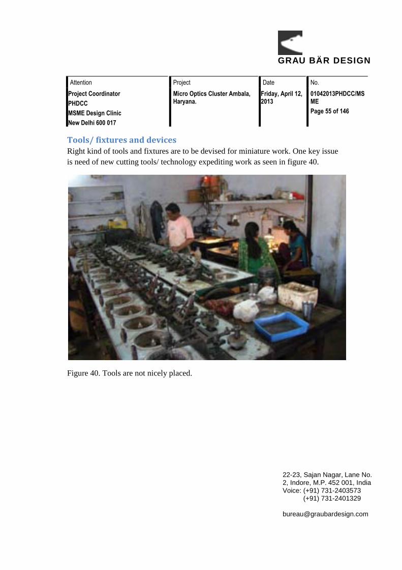
Tools/ fixtures and devices Right kind of tools and fixtures are to be devised for miniature work. One key issue is need of new cutting tools/ technology expediting work as seen in figure 40.
Figure 40. Tools are not nicely placed.

GRAU BÄR DESIGN
Attention Project Date No. Project Coordinator PHDCC MSME Design Clinic New Delhi 600 017
Micro Optics Cluster Ambala, Haryana.
Friday, April 12, 2013
01042013PHDCC/MSME Page 56 of 146
22-23, Sajan Nagar, Lane No. 2, Indore, M.P. 452 001, India Voice: (+91) 731-2403573 (+91) 731-2401329 [email protected]
Forward and backward linkages Though not exactly covered under the umbrella of design this also is a key issue expressed by first as well as second generation entrepreneurs. Some help in this direction may carry it a long way as shown I figure 41.
Figure 41. No linkages resulting in bad quality of workplace.

GRAU BÄR DESIGN
Attention Project Date No. Project Coordinator PHDCC MSME Design Clinic New Delhi 600 017
Micro Optics Cluster Ambala, Haryana.
Friday, April 12, 2013
01042013PHDCC/MSME Page 57 of 146
22-23, Sajan Nagar, Lane No. 2, Indore, M.P. 452 001, India Voice: (+91) 731-2403573 (+91) 731-2401329 [email protected]
Statement of Needs
GRAU BÄR DESIGN
Attention Project Date No. Project Coordinator PHDCC MSME Design Clinic New Delhi 600 017
Micro Optics Cluster Ambala, Haryana.
Friday, April 12, 2013
01042013PHDCC/MSME Page 58 of 146
22-23, Sajan Nagar, Lane No. 2, Indore, M.P. 452 001, India Voice: (+91) 731-2403573 (+91) 731-2401329 [email protected]
Statement of needs can be summarized as; design intervention is needed and can help in
• Workplace organization and work envelop optimization • Process design and its (graphic) representation with critical points of control
established • Inputs to improve postural and visual Ergonomics, Illumination and
ventilation • Inputs for a model workstation, with help of a few attachments • Suggestions for Shop floor plan

GRAU BÄR DESIGN
Attention Project Date No. Project Coordinator PHDCC MSME Design Clinic New Delhi 600 017
Micro Optics Cluster Ambala, Haryana.
Friday, April 12, 2013
01042013PHDCC/MSME Page 59 of 146
22-23, Sajan Nagar, Lane No. 2, Indore, M.P. 452 001, India Voice: (+91) 731-2403573 (+91) 731-2401329 [email protected]
Conclusion

GRAU BÄR DESIGN
Attention Project Date No. Project Coordinator PHDCC MSME Design Clinic New Delhi 600 017
Micro Optics Cluster Ambala, Haryana.
Friday, April 12, 2013
01042013PHDCC/MSME Page 60 of 146
22-23, Sajan Nagar, Lane No. 2, Indore, M.P. 452 001, India Voice: (+91) 731-2403573 (+91) 731-2401329 [email protected]
There is a clear and present potential design clinic projects in Micro Optics cluster in Ambala. The key areas where meaningful contributions, by way of industrial design, can me made are listed in need statement. These can be addressed in a group as well as on an individual basis.
At a future date establishing a common facility centre is highly advisable specifically to develop special purpose tools.

GRAU BÄR DESIGN
Attention Project Date No. Project Coordinator PHDCC MSME Design Clinic New Delhi 600 017
Micro Optics Cluster Ambala, Haryana.
Friday, April 12, 2013
01042013PHDCC/MSME Page 61 of 146
22-23, Sajan Nagar, Lane No. 2, Indore, M.P. 452 001, India Voice: (+91) 731-2403573 (+91) 731-2401329 [email protected]
Annexure

GRAU BÄR DESIGN
Attention Project Date No. Project Coordinator PHDCC MSME Design Clinic New Delhi 600 017
Micro Optics Cluster Ambala, Haryana.
Friday, April 12, 2013
01042013PHDCC/MSME Page 62 of 146
22-23, Sajan Nagar, Lane No. 2, Indore, M.P. 452 001, India Voice: (+91) 731-2403573 (+91) 731-2401329 [email protected]
List of Manufacturing Units Sr No.
Company Name Mailing Address
1. Hari Optik A-18, Tribune Colony, Ambala Cantt. - 133001
2. Maha Lakshmi Optics & Instruments
3131- Chhota Shiwala, Kacha Bazar, Ambala Cantt. - 133001
3. Creative Mind Solutions & Research Labs
Near Bank of Baroda, Dosarka, Ambala.
4. Sudheer Scientific Works 1265, Bengali Mohalla, Ambala Cantt. - 133001
5. Ambey Optics Ram Bagh Road, Asarfi Bagh Compound, Ambala Cantt. - 133001
6. Labotron Instruments Limited 10, H.S.I.D.C. Industrial Estate, Ambala Cantt. - 133001
7. Ramsun Instruments 85, Vikas Puri (Sai Nagar), Near Industrial Area, Jagadhri Road, Ambala Cantt. - 133001
8. Amarson's Industries 2539, Bngali Street, Hargolal Road, Ambala Cantt. - 133001
9. Ideal Package Inc. 64-65, Indira Colony, Rampur Sarsheri Road, Ambala Cantt. - 133001
10. Jay Kay Optik 24-26, New Preet Nagar, Behind Shiv Mandir, Ambala Cantt. - 133001
11. Dolphin Micro Optics 751/34, Siklighar Mohalla, Ambala Cantt. - 133001
12. Quality Scientific & Mechanical Works
4, Cross Road, Ambala Cantt. - 133001
13. Laicon India 47- A, Azad Nagar, Opp. Puja filling Statin, Ambala Cantt. - 133001
14. Ray Bright Technologies 18, Industrial Estate, Jagadhri Road, Ambala Cantt. - 133001
15. Ajay Opticals 592-95, Ram Bagh Road, Opp. Govt. High School, Ambala Cantt.- 133001

GRAU BÄR DESIGN
Attention Project Date No. Project Coordinator PHDCC MSME Design Clinic New Delhi 600 017
Micro Optics Cluster Ambala, Haryana.
Friday, April 12, 2013
01042013PHDCC/MSME Page 63 of 146
22-23, Sajan Nagar, Lane No. 2, Indore, M.P. 452 001, India Voice: (+91) 731-2403573 (+91) 731-2401329 [email protected]
16. Labomad 903, 9th floor, Time Tower Sec-28, M. G. Road Gurgaon-122002
17. G. H. Optics 37-A, Gobind Nagar, Ambala Cantt.-133001
18. Doon Scientific Laboratories 11-9/5, Vimla Bhawan, Durga Naga, Ambala Cantt. - 133001

GRAU BÄR DESIGN
Attention Project Date No. Project Coordinator PHDCC MSME Design Clinic New Delhi 600 017
Micro Optics Cluster Ambala, Haryana.
Friday, April 12, 2013
01042013PHDCC/MSME Page 64 of 146
22-23, Sajan Nagar, Lane No. 2, Indore, M.P. 452 001, India Voice: (+91) 731-2403573 (+91) 731-2401329 [email protected]
Contact Persons
Sr No.
Company Name Name / Contact Number
Email ID
1. Hari Optik Kameshwar Chopra +91 90343 44403
2. Maha Lakshmi Optics & Instruments
Rajpal Walia +91 98963 00315
3. Creative Mind Solutions & Research Labs
Vishal Bhandari +91 97293 63094
4. Sudheer Scientific Works
Sudheer Kumar +91 94160 25615
[email protected], [email protected]
5. Ambey Optics Rakesh Dhiman +91 98966 23127
6. Labotron Instruments Limited
Neeraj Jain +91 98960 37999
7. Ramsun Instruments Tara Chand +91 94163 78410
8. Amarson's Industries Ashwani Goel +91 98962 01350
[email protected], [email protected]
9. Ideal Package Inc. Vikram Singh +91 98120 07073
10. Jay Kay Optik Vikas Passi +91 98960 03702
11. Dolphin Micro Optics
Amit Sabharwal +91 94161 75070
12. Quality Scientific & Mechanical Works
Neeraj Bahl +91 94160 29546
13. Laicon India Mam Chand +91 94662 11827
14. Ray Bright Technologies
Pranay Chowdhary +91 98139 68007

GRAU BÄR DESIGN
Attention Project Date No. Project Coordinator PHDCC MSME Design Clinic New Delhi 600 017
Micro Optics Cluster Ambala, Haryana.
Friday, April 12, 2013
01042013PHDCC/MSME Page 65 of 146
22-23, Sajan Nagar, Lane No. 2, Indore, M.P. 452 001, India Voice: (+91) 731-2403573 (+91) 731-2401329 [email protected]
15. Ajay Opticals Ajay Bhatia +91 94161 75039
16. Labomad Puneet Gupta +91 82959 46555
17. G. H. Optics Gurpreet Walia +91 90178 19883
18. Doon Scientific Laboratories
Mahesh Gupta +91 94665 09276

GRAU BÄR DESIGN
Attention Project Date No. Project Coordinator PHDCC MSME Design Clinic New Delhi 600 017
Micro Optics Cluster Ambala, Haryana.
Friday, April 12, 2013
01042013PHDCC/MSME Page 66 of 146
22-23, Sajan Nagar, Lane No. 2, Indore, M.P. 452 001, India Voice: (+91) 731-2403573 (+91) 731-2401329 [email protected]
Annexure 1 Lens

GRAU BÄR DESIGN
Attention Project Date No. Project Coordinator PHDCC MSME Design Clinic New Delhi 600 017
Micro Optics Cluster Ambala, Haryana.
Friday, April 12, 2013
01042013PHDCC/MSME Page 67 of 146
22-23, Sajan Nagar, Lane No. 2, Indore, M.P. 452 001, India Voice: (+91) 731-2403573 (+91) 731-2401329 [email protected]
Construction of simple lenses
Most lenses are spherical lenses: their two surfaces are parts of the surfaces of spheres, with the lens axis ideally perpendicular to both surfaces. Each surface can be convex as shown in figure 41(bulging outwards from the lens), concave as in figure 42(depressed into the lens), or planar (flat). The line joining the centres of the spheres making up the lens surfaces is called the axis of the lens. Typically the lens axis passes through the physical centre of the lens, because of the way they are manufactured. Lenses may be cut or ground after manufacturing to give them a different shape or size. The lens axis may then not pass through the physical centre of the lens.
Figure 41. Convex lens.

GRAU BÄR DESIGN
Attention Project Date No. Project Coordinator PHDCC MSME Design Clinic New Delhi 600 017
Micro Optics Cluster Ambala, Haryana.
Friday, April 12, 2013
01042013PHDCC/MSME Page 68 of 146
22-23, Sajan Nagar, Lane No. 2, Indore, M.P. 452 001, India Voice: (+91) 731-2403573 (+91) 731-2401329 [email protected]
Figure 42. Concave lens.
Toric or sphero-cylindrical lenses have surfaces with two different radii of curvature in two orthogonal planes as shown in figure 43. They have a different focal power in different meridians. This is a form of deliberate astigmatism.

GRAU BÄR DESIGN
Attention Project Date No. Project Coordinator PHDCC MSME Design Clinic New Delhi 600 017
Micro Optics Cluster Ambala, Haryana.
Friday, April 12, 2013
01042013PHDCC/MSME Page 69 of 146
22-23, Sajan Nagar, Lane No. 2, Indore, M.P. 452 001, India Voice: (+91) 731-2403573 (+91) 731-2401329 [email protected]
Figure 43. Illustration for toric or sphero-cylindrical lens.
More complex are aspheric lenses. These are lenses where one or both surfaces have a shape that is neither spherical nor cylindrical. Such lenses can produce images with much less aberration than standard simple lenses. These in turn evolved into freeform (digital/adaptive/corrected curve) spectacle lenses, where up to 20,000 ray paths are calculated from the eye to the image taking into account the position of the eye and the differing back vertex distance of the lens surface and its pantoscopic tilt and face form angle. The lens surface(s) are digitally adapted at nanometer levels (normally by a diamond stylus) to eliminate spherical aberration, coma and oblique astigmatism. This type of lens design almost completely fulfills the sagittal and tangential image shell requirements first described by Tscherning in 1925 and further described by Wollaston and Ostwalt. These advanced designs of spectacle lens can improve the visual performance by up to 70% particularly in the periphery.

GRAU BÄR DESIGN
Attention Project Date No. Project Coordinator PHDCC MSME Design Clinic New Delhi 600 017
Micro Optics Cluster Ambala, Haryana.
Friday, April 12, 2013
01042013PHDCC/MSME Page 70 of 146
22-23, Sajan Nagar, Lane No. 2, Indore, M.P. 452 001, India Voice: (+91) 731-2403573 (+91) 731-2401329 [email protected]
Aberrations
Lenses do not form perfect images, and there is always some degree of distortion or aberration introduced by the lens which causes the image to be an imperfect replica of the object. Careful design of the lens system for a particular application ensures that the aberration is minimized. There are several different types of aberration which can affect image quality.
Spherical aberration
Spherical aberration occurs because spherical surfaces are not the ideal shape with which to make a lens, but they are by far the simplest shape to which glass can be ground and polished and so are often used. Spherical aberration causes beams parallel to, but distant from, the lens axis to be focused in a slightly different place than beams close to the axis as shown in figure 44. This manifests itself as a blurring of the image. Lenses in which closer-to-ideal, non-spherical surfaces are used are called aspheric lenses. These were formerly complex to make and often extremely expensive, but advances in technology have greatly reduced the manufacturing cost for such lenses. Spherical aberration can be minimised by careful choice of the curvature of the surfaces for a particular application: for instance, a plano-convex lens which is used to focus a collimated beam produces a sharper focal spot when used with the convex side towards the beam source.

GRAU BÄR DESIGN
Attention Project Date No.Project CoordinatorPHDCCMSME Design ClinicNew Delhi 600 017
Micro Optics Cluster Ambala, Haryana.
Friday, April 12, 2013
01042013PHDCC/MSMEPage 71 of 146
22-23, Sajan Nagar, Lane No. 2, Indore, M.P. 452 001, IndiaVoice: (+91) 731-2403573 (+91) 731-2401329 [email protected]
Figure 44. A line diagram showing spherical aberration of light.
Coma
Another type of aberration is coma, which derives its name from the comet-like appearance of the aberrated image. Coma occurs when an object off the optical axis of the lens is imaged, where rays pass through the lens at an angle to the axis θ. Rays which pass through the centre of the lens of focal length f are focused at a point with distance f tan θ from the axis. Rays passing through the outer margins of the lens are focused at different points, either further from the axis (positive coma) or closer to the axis (negative coma). In general, a bundle of parallel rays passing through the lens at a fixed distance from the centre of the lens are focused to a ring-shaped image in the focal plane, known as a comatic circle as seen in figure 45. The sum of all these circles results in a V-shaped or comet-like flare. As with spherical aberration, coma can be minimised (and in some cases eliminated) by choosing the curvature of the two lens surfaces to match the application. Lenses in which both spherical aberration and coma are minimised are called bestform lenses.

GRAU BÄR DESIGN
Attention Project Date No.Project CoordinatorPHDCCMSME Design ClinicNew Delhi 600 017
Micro Optics Cluster Ambala, Haryana.
Friday, April 12, 2013
01042013PHDCC/MSMEPage 72 of 146
22-23, Sajan Nagar, Lane No. 2, Indore, M.P. 452 001, IndiaVoice: (+91) 731-2403573 (+91) 731-2401329 [email protected]
Figure 45. A line diagram showing a coma.
Chromatic aberration
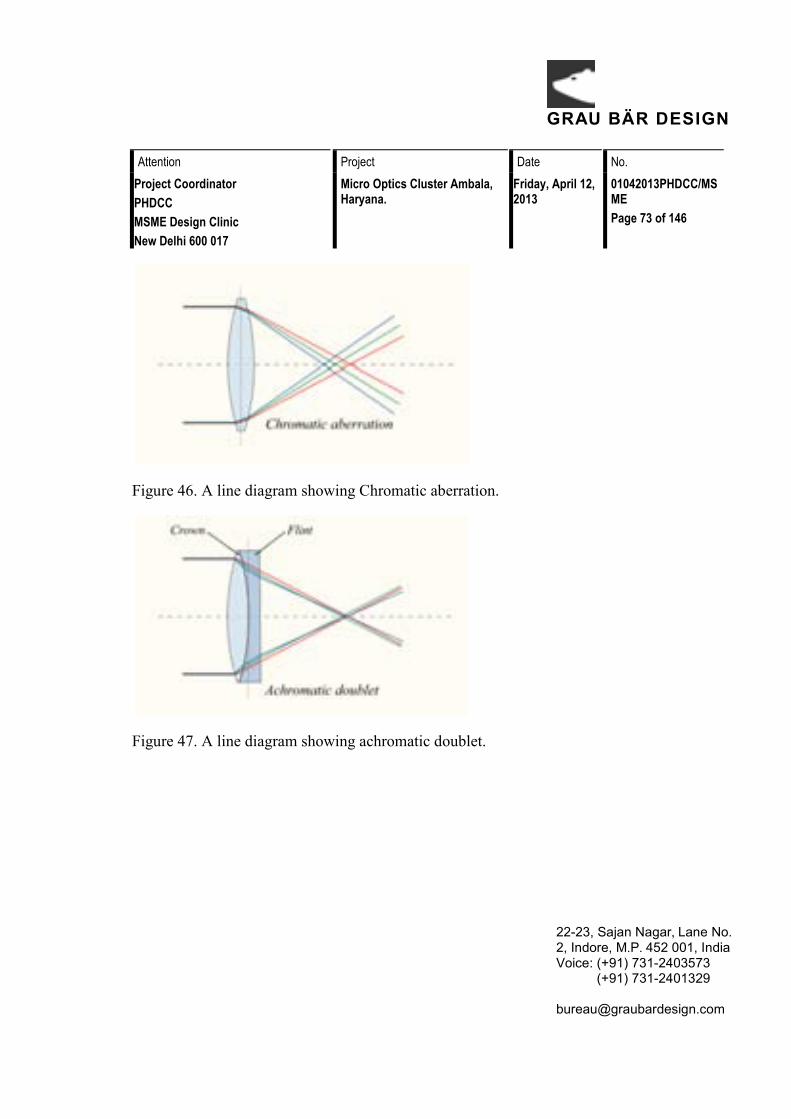
Chromatic aberration is caused by the dispersion of the lens material—the variation of its refractive index, n, with the wavelength of light. Since, from the formulae above, f is dependent upon n, it follows that different wavelengths of light will be focused to different positions. Chromatic aberration of a lens is seen as fringes of colour around the image. It can be minimised by using an achromatic doublet (or achromat) in which two materials with differing dispersion are bonded together to form a single lens. This reduces the amount of chromatic aberration over a certain range of wavelengths, though it does not produce perfect correction. The use of achromats was an important step in the development of the optical microscope. An apochromat is a lens or lens system which has even better correction of chromatic aberration, combined with improved correction of spherical aberration. Apochromats are much more expensive than achromats as shown in figure 46 & 47.
Different lens materials may also be used to minimise chromatic aberration, such as specialised coatings or lenses made from the crystal fluorite. This naturally occurring substance has the highest known Abbe number, indicating that the material has low dispersion.
GRAU BÄR DESIGN
Attention Project Date No.Project CoordinatorPHDCCMSME Design ClinicNew Delhi 600 017
Micro Optics Cluster Ambala, Haryana.
Friday, April 12, 2013
01042013PHDCC/MSMEPage 73 of 146
22-23, Sajan Nagar, Lane No. 2, Indore, M.P. 452 001, IndiaVoice: (+91) 731-2403573 (+91) 731-2401329 [email protected]
Figure 46. A line diagram showing Chromatic aberration.
Figure 47. A line diagram showing achromatic doublet.

GRAU BÄR DESIGN
Attention Project Date No.Project CoordinatorPHDCCMSME Design ClinicNew Delhi 600 017
Micro Optics Cluster Ambala, Haryana.
Friday, April 12, 2013
01042013PHDCC/MSMEPage 74 of 146
22-23, Sajan Nagar, Lane No. 2, Indore, M.P. 452 001, IndiaVoice: (+91) 731-2403573 (+91) 731-2401329 [email protected]
Types of simple lenses
Figure 48. Depicts example of types of simple lenses.
Lenses are classified by the curvature of the two optical surfaces as shown in figure 48. A lens is biconvex (or double convex, or just convex) if both surfaces are convex.If both surfaces have the same radius of curvature, the lens is equiconvex. A lens with two concave surfaces is biconcave (or just concave). If one of the surfaces is flat, the lens is plano-convex or plano-concave depending on the curvature of the other surface. A lens with one convex and one concave side is convex-concave or meniscus. It is this type of lens that is most commonly used in corrective lenses.
If the lens is biconvex or plano-convex, a collimated beam of light travelling parallel to the lens axis and passing through the lens will be converged (or focused) to a spot on the axis, at a certain distance behind the lens (known as the focal length). In this case, the lens is called a positive or converging lens as shown in figure 49.

GRAU BÄR DESIGN
Attention Project Date No.Project CoordinatorPHDCCMSME Design ClinicNew Delhi 600 017
Micro Optics Cluster Ambala, Haryana.
Friday, April 12, 2013
01042013PHDCC/MSMEPage 75 of 146
22-23, Sajan Nagar, Lane No. 2, Indore, M.P. 452 001, IndiaVoice: (+91) 731-2403573 (+91) 731-2401329 [email protected]
Figure 49. Shows line diagram of converging lens.
If the lens is biconcave or plano-concave, a collimated beam of light passing through the lens is diverged (spread); the lens is thus called a negative or diverging lens as shown in figure 50. The beam after passing through the lens appears to be emanating from a particular point on the axis in front of the lens; the distance from this point to the lens is also known as the focal length, although it is negative with respect to the focal length of a converging lens.

GRAU BÄR DESIGN
Attention Project Date No.Project CoordinatorPHDCCMSME Design ClinicNew Delhi 600 017
Micro Optics Cluster Ambala, Haryana.
Friday, April 12, 2013
01042013PHDCC/MSMEPage 76 of 146
22-23, Sajan Nagar, Lane No. 2, Indore, M.P. 452 001, IndiaVoice: (+91) 731-2403573 (+91) 731-2401329 [email protected]
Figure 50. Shows line diagram of diverging lens.
Convex-concave (meniscus) lenses can be either positive or negative, depending on the relative curvatures of the two surfaces. A negative meniscus lens has a steeperconcave surface and will be thinner at the centre than at the periphery. Conversely, a positive meniscus lens has a steeper convex surface and will be thicker at the centre than at the periphery. An ideal thin lens with two surfaces of equal curvature would have zero optical power, meaning that it would neither converge nor diverge light. All real lenses have a nonzero thickness, however, which affects the optical power. To obtain exactly zero optical power, a meniscus lens must have slightly unequal curvatures to account for the effect of the lens' thickness.

GRAU BÄR DESIGN
Attention Project Date No.Project CoordinatorPHDCCMSME Design ClinicNew Delhi 600 017
Micro Optics Cluster Ambala, Haryana.
Friday, April 12, 2013
01042013PHDCC/MSMEPage 77 of 146
22-23, Sajan Nagar, Lane No. 2, Indore, M.P. 452 001, IndiaVoice: (+91) 731-2403573 (+91) 731-2401329 [email protected]
Lensmaker's equation
The focal length of a lens in air can be calculated from the lensmaker's equation
where
P is the power of the lens,
F is the focal length of the lens,
N is the refractive index of the lens material,
R1 is the radius of curvature of the lens surface closest to the light source,
R2 is the radius of curvature of the lens surface farthest from the light source, and
d is the thickness of the lens (the distance along the lens axis between the two surface vertices).
Sign convention of lens radii R1 and R2
The signs of the lens' radii of curvature indicate whether the corresponding surfaces are convex or concave. The sign convention used to represent this varies, but in this article if R1 is positive the first surface is convex, and if R1 is negative the surface is concave. The signs are reversed for the back surface of the lens: if R2 is positive the surface is concave, and if R2 is negative the surface is convex. If either radius is infinite, the corresponding surface is flat. With this convention the signs are determined by the shapes of the lens surfaces, and are independent of the direction in which light travels through the lens.

GRAU BÄR DESIGN
Attention Project Date No.Project CoordinatorPHDCCMSME Design ClinicNew Delhi 600 017
Micro Optics Cluster Ambala, Haryana.
Friday, April 12, 2013
01042013PHDCC/MSMEPage 78 of 146
22-23, Sajan Nagar, Lane No. 2, Indore, M.P. 452 001, IndiaVoice: (+91) 731-2403573 (+91) 731-2401329 [email protected]
Imaging properties
As mentioned above, a positive or converging lens in air will focus a collimated beam travelling along the lens axis to a spot (known as the focal point) at a distance f from the lens. Conversely, a point source of light placed at the focal point will be converted into a collimated beam by the lens. These two cases are examples of imageformation in lenses. In the former case, an object at an infinite distance (as represented by a collimated beam of waves) is focused to an image at the focal point of the lens. In the latter, an object at the focal length distance from the lens is imaged at infinity. The plane perpendicular to the lens axis situated at a distance f from the lens is called the focal plane.
Figure 51. Ray diagram.
If the distances from the object to the lens and from the lens to the image are S1 and S2 respectively, for a lens of negligible thickness, in air, the distanc es are related by the thin lens formula as seen in figure 51.

GRAU BÄR DESIGN
Attention Project Date No. Project Coordinator PHDCC MSME Design Clinic New Delhi 600 017
Micro Optics Cluster Ambala, Haryana.
Friday, April 12, 2013
01042013PHDCC/MSME Page 79 of 146
22-23, Sajan Nagar, Lane No. 2, Indore, M.P. 452 001, India Voice: (+91) 731-2403573 (+91) 731-2401329 [email protected]

GRAU BÄR DESIGN
Attention Project Date No. Project Coordinator PHDCC MSME Design Clinic New Delhi 600 017
Micro Optics Cluster Ambala, Haryana.
Friday, April 12, 2013
01042013PHDCC/MSME Page 80 of 146
22-23, Sajan Nagar, Lane No. 2, Indore, M.P. 452 001, India Voice: (+91) 731-2403573 (+91) 731-2401329 [email protected]
Annexure 2 Prism

GRAU BÄR DESIGN
Attention Project Date No. Project Coordinator PHDCC MSME Design Clinic New Delhi 600 017
Micro Optics Cluster Ambala, Haryana.
Friday, April 12, 2013
01042013PHDCC/MSME Page 81 of 146
22-23, Sajan Nagar, Lane No. 2, Indore, M.P. 452 001, India Voice: (+91) 731-2403573 (+91) 731-2401329 [email protected]
Prism (optics)
In optics, a prism is a transparent optical element with flat, polished surfaces that refract light. At least two of the flat surfaces must have an angle between them. The exact angles between the surfaces depend on the application. The traditional geometrical shape is that of a triangular prism with a triangular base and rectangular sides, and in colloquial use "prism" usually refers to this type. Some types of optical prism are not in fact in the shape of geometric prisms. Prisms can be made from any material that is transparent to the wavelengths for which they are designed. Typical materials include glass, plastic and fluorite.
Figure 52. An example of plastic prism.
A prism can be used to break light up into its constituent spectral colors (the colors of the rainbow) as shown in figure 52. Prisms can also be used to reflect light, or to split light into components with different polarizations.

GRAU BÄR DESIGN
Attention Project Date No. Project Coordinator PHDCC MSME Design Clinic New Delhi 600 017
Micro Optics Cluster Ambala, Haryana.
Friday, April 12, 2013
01042013PHDCC/MSME Page 82 of 146
22-23, Sajan Nagar, Lane No. 2, Indore, M.P. 452 001, India Voice: (+91) 731-2403573 (+91) 731-2401329 [email protected]
How prisms work
Light changes speed as it moves from one medium to another (for example, from air into the glass of the prism). This speed change causes the light to be refracted and to enter the new medium at a different angle (Huygens principle). The degree of bending of the light's path depends on the angle that the incident beam of light makes with the surface, and on the ratio between the refractive indices of the two media (Snell's law). The refractive index of many materials (such as glass) varies with the wavelength or color of the light used, a phenomenon known as dispersion. This causes light of different colors to be refracted differently and to leave the prism at different angles, creating an effect similar to a rainbow. This can be used to separate a beam of white light into its constituent spectrum of colors. Prisms will generally disperse light over a much larger frequency bandwidth than diffraction gratings, making them useful for broad-spectrum spectroscopy. Furthermore, prisms do not suffer from complications arising from overlapping spectral orders, which all gratings have.
Prisms are sometimes used for the internal reflection at the surfaces rather than for dispersion as seen in figure 53. If light inside the prism hits one of the surfaces at a sufficiently steep angle, total internal reflection occurs and all of the light is

GRAU BÄR DESIGN
Attention Project Date No. Project Coordinator PHDCC MSME Design Clinic New Delhi 600 017
Micro Optics Cluster Ambala, Haryana.
Friday, April 12, 2013
01042013PHDCC/MSME Page 83 of 146
22-23, Sajan Nagar, Lane No. 2, Indore, M.P. 452 001, India Voice: (+91) 731-2403573 (+91) 731-2401329 [email protected]
reflected. This makes a prism a useful substitute for a mirror in some situations.
Figure 53. Example depicting, how prism works.
Deviation angle and dispersion
Ray angle deviation and dispersion through a prism can be determined by tracing a sample ray through the element and using Snell's law at each interface. For the prism shown at right, the indicated angles are given by

GRAU BÄR DESIGN
Attention Project Date No.Project CoordinatorPHDCCMSME Design ClinicNew Delhi 600 017
Micro Optics Cluster Ambala, Haryana.
Friday, April 12, 2013
01042013PHDCC/MSMEPage 84 of 146
22-23, Sajan Nagar, Lane No. 2, Indore, M.P. 452 001, IndiaVoice: (+91) 731-2403573 (+91) 731-2401329 [email protected]
Figure 54. a ray passing through prism, and creates an angle.
Prisms and the nature of light
Before Isaac Newton, it was believed that white light was colorless, and that the prism itself produced the color. Newton's experiments demonstrated that all the colors already existed in the light in a heterogeneous fashion, and that "corpuscles" (particles) of light were fanned out because particles with different colors traveled with different speeds through the prism. It was only later that Young and Fresnelcombined Newton's particle theory with Huygens' wave theory to show that color is the visible manifestation of light's wavelength.

GRAU BÄR DESIGN
Attention Project Date No. Project Coordinator PHDCC MSME Design Clinic New Delhi 600 017
Micro Optics Cluster Ambala, Haryana.
Friday, April 12, 2013
01042013PHDCC/MSME Page 85 of 146
22-23, Sajan Nagar, Lane No. 2, Indore, M.P. 452 001, India Voice: (+91) 731-2403573 (+91) 731-2401329 [email protected]
Figure 55. A triangular prism dispersing light.
Newton arrived at his conclusion by passing the red color from one prism through a second prism and found the color unchanged (Figure 55). From this, he concluded that the colors must already be present in the incoming light — thus, the prism did not create colors, but merely separated colors that are already there. He also used a lens and a second prism to recompose the spectrum back into white light. This experiment has become a classic example of the methodology introduced during the scientific revolution. The results of this experiment dramatically transformed the field of metaphysics, leading to John Locke's primary vs secondary quality distinction.
Newton discussed prism dispersion in great detail in his book Opticks. He also introduced the use of more than one prism to control dispersion. Newton's description of his experiments on prism dispersion was qualitative, and is quite readable. A quantitative description of multiple-prism dispersion was not needed until multiple prism laser beam expanders were introduced in the 1980s.

GRAU BÄR DESIGN
Attention Project Date No. Project Coordinator PHDCC MSME Design Clinic New Delhi 600 017
Micro Optics Cluster Ambala, Haryana.
Friday, April 12, 2013
01042013PHDCC/MSME Page 86 of 146
22-23, Sajan Nagar, Lane No. 2, Indore, M.P. 452 001, India Voice: (+91) 731-2403573 (+91) 731-2401329 [email protected]
Types of prisms
There are various types of prism :
• Dispersive prisms • Triangular prism • Abbe prism • Pellin–Broca prism • Amici prism • Compound prism
Grating and prism mountings
There are six grating/prism configurations which are considered to be "classics":[4]
• Paschen-Runge • Eagle • Wadsworth • Ebert-Fasti • Littrow • Pfund
Grisms (grating prisms)
Diffraction gratings may be replicated onto prisms to form grating prisms, called "grisms". A transmission grism is a useful component in an astronomical telescope, allowing observation of stellar spectra. A reflection grating replicated onto a prism

GRAU BÄR DESIGN
Attention Project Date No. Project Coordinator PHDCC MSME Design Clinic New Delhi 600 017
Micro Optics Cluster Ambala, Haryana.
Friday, April 12, 2013
01042013PHDCC/MSME Page 87 of 146
22-23, Sajan Nagar, Lane No. 2, Indore, M.P. 452 001, India Voice: (+91) 731-2403573 (+91) 731-2401329 [email protected]
allows light to diffract inside the prism medium, which increases the dispersion by the ratio of refractive index of that medium to that of air.
Reflective prisms
Reflective prisms are used to reflect light, in order to flip, invert, rotate, deviate or displace the light beam. They are typically used to erect the image in binoculars or single-lens reflex cameras – without the prisms the image would be upside down for the user. Many reflective prisms use total internal reflection to achieve high reflectivity.
The most common reflective prisms are:
• Porro prism • Porro–Abbe prism • Amici roof prism • Pentaprism and roof pentaprism • Abbe–Koenig prism • Schmidt–Pechan prism • Bauernfeind prism • Dove prism • Retroreflector prism
Beam-splitting prisms
Some reflective prisms are used for splitting a beam into two or more beams:
• Beam splitter cube • Dichroic prism • Polarizing prisms

GRAU BÄR DESIGN
Attention Project Date No. Project Coordinator PHDCC MSME Design Clinic New Delhi 600 017
Micro Optics Cluster Ambala, Haryana.
Friday, April 12, 2013
01042013PHDCC/MSME Page 88 of 146
22-23, Sajan Nagar, Lane No. 2, Indore, M.P. 452 001, India Voice: (+91) 731-2403573 (+91) 731-2401329 [email protected]
There are also polarizing prisms which can split a beam of light into components of varying polarization. These are typically made of a birefringent crystalline material.
• Nicol prism • Wollaston prism • Nomarski prism – a variant of the Wollaston prism with advantages in
microscopy • Rochon prism • Sénarmont prism • Glan–Foucault prism • Glan–Taylor prism • Glan–Thompson prism
Deflecting prisms
Wedge prisms are used to deflect a beam of light by a fixed angle. A pair of such prisms can be used for beam steering; by rotating the prisms the beam can be deflected into any desired angle within a conical "field of regard". The most commonly found implementation is a Risley prism pair. Two wedge prisms can also be used as an anamorphic pair to change the shape of a beam. This is used to make a round beam from the elliptical output of a laser diode.
Rhomboid prisms are used to laterally displace a beam of light without inverting the image.
Deck prisms were used on sailing ships to bring daylight below deck, since candles and kerosene lamps are a fire hazard on wooden ships.

GRAU BÄR DESIGN
Attention Project Date No. Project Coordinator PHDCC MSME Design Clinic New Delhi 600 017
Micro Optics Cluster Ambala, Haryana.
Friday, April 12, 2013
01042013PHDCC/MSME Page 89 of 146
22-23, Sajan Nagar, Lane No. 2, Indore, M.P. 452 001, India Voice: (+91) 731-2403573 (+91) 731-2401329 [email protected]
Annexure 3 Optical Microscope

GRAU BÄR DESIGN
Attention Project Date No. Project Coordinator PHDCC MSME Design Clinic New Delhi 600 017
Micro Optics Cluster Ambala, Haryana.
Friday, April 12, 2013
01042013PHDCC/MSME Page 90 of 146
22-23, Sajan Nagar, Lane No. 2, Indore, M.P. 452 001, India Voice: (+91) 731-2403573 (+91) 731-2401329 [email protected]
Optical microscope
The optical microscope, often referred to as the "light microscope", is a type of microscope which uses visible light and a system of lenses to magnify images of small samples. Optical microscopes are the oldest design of microscope and were possibly designed in their present compound form in the 17th century. Basic optical microscopes can be very simple, although there are many complex designs which aim to improve resolution and sample contrast. Historically optical microscopes were easy to develop and are popular because they use visible light so that samples may be directly observed by eye.

GRAU BÄR DESIGN
Attention Project Date No. Project Coordinator PHDCC MSME Design Clinic New Delhi 600 017
Micro Optics Cluster Ambala, Haryana.
Friday, April 12, 2013
01042013PHDCC/MSME Page 91 of 146
22-23, Sajan Nagar, Lane No. 2, Indore, M.P. 452 001, India Voice: (+91) 731-2403573 (+91) 731-2401329 [email protected]
Figure 56. A compound microscope.
The image from an optical microscope can be captured by normal light-sensitive cameras to generate a micrograph as shown in figure 56. Originally images were captured by photographic film but modern developments in CMOS and charge-coupled device (CCD) cameras allow the capture of digital images. Purely digital microscopes are now available which use a CCD camera to examine a sample,

GRAU BÄR DESIGN
Attention Project Date No. Project Coordinator PHDCC MSME Design Clinic New Delhi 600 017
Micro Optics Cluster Ambala, Haryana.
Friday, April 12, 2013
01042013PHDCC/MSME Page 92 of 146
22-23, Sajan Nagar, Lane No. 2, Indore, M.P. 452 001, India Voice: (+91) 731-2403573 (+91) 731-2401329 [email protected]
showing the resulting image directly on a computer screen without the need for eyepieces.
Alternatives to optical microscopy which do not use visible light include scanning electron microscopy and transmission electron microscopy.
Optical configurations
There are two basic configurations of the conventional optical microscope: the simple (single lens) and the compound (many lenses). The vast majority of modern research microscopes are compound microscopes while some cheaper commercial digital microscopes are simple single lens microscopes. A magnifying glass is, in essence, a basic single lens microscope. In general, microscope optics are static; to focus at different focal depths the lens to sample distance is adjusted, and to get a wider or narrower field of view a different magnification objective lens must be used. Most modern research microscopes also have a separate set of optics for illuminating the sample.
Single lens (simple) microscope
A simple microscope is a microscope that uses only one lens for magnification, and is the original design of light microscope. Van Leeuwenhoek's microscopes consisted of a small, single converging lens mounted on a brass plate, with a screw mechanism to hold the sample or specimen to be examined. Demonstrations by British microscopist have images from such basic instruments. Though now considered primitive, the use of a single, convex lens for viewing is still found in simple magnification devices, such as the magnifying glass and the loupe.
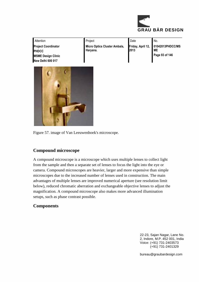
GRAU BÄR DESIGN
Attention Project Date No. Project Coordinator PHDCC MSME Design Clinic New Delhi 600 017
Micro Optics Cluster Ambala, Haryana.
Friday, April 12, 2013
01042013PHDCC/MSME Page 93 of 146
22-23, Sajan Nagar, Lane No. 2, Indore, M.P. 452 001, India Voice: (+91) 731-2403573 (+91) 731-2401329 [email protected]
Figure 57. image of Van Leeuwenhoek's microscope.
Compound microscope
A compound microscope is a microscope which uses multiple lenses to collect light from the sample and then a separate set of lenses to focus the light into the eye or camera. Compound microscopes are heavier, larger and more expensive than simple microscopes due to the increased number of lenses used in construction. The main advantages of multiple lenses are improved numerical aperture (see resolution limit below), reduced chromatic aberration and exchangeable objective lenses to adjust the magnification. A compound microscope also makes more advanced illumination setups, such as phase contrast possible.
Components
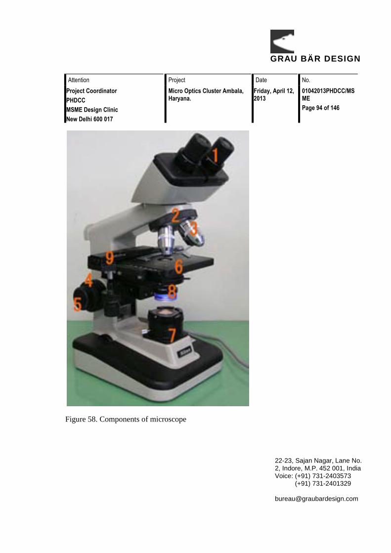
GRAU BÄR DESIGN
Attention Project Date No. Project Coordinator PHDCC MSME Design Clinic New Delhi 600 017
Micro Optics Cluster Ambala, Haryana.
Friday, April 12, 2013
01042013PHDCC/MSME Page 94 of 146
22-23, Sajan Nagar, Lane No. 2, Indore, M.P. 452 001, India Voice: (+91) 731-2403573 (+91) 731-2401329 [email protected]
Figure 58. Components of microscope

GRAU BÄR DESIGN
Attention Project Date No. Project Coordinator PHDCC MSME Design Clinic New Delhi 600 017
Micro Optics Cluster Ambala, Haryana.
Friday, April 12, 2013
01042013PHDCC/MSME Page 95 of 146
22-23, Sajan Nagar, Lane No. 2, Indore, M.P. 452 001, India Voice: (+91) 731-2403573 (+91) 731-2401329 [email protected]
All modern optical microscopes designed for viewing samples by transmitted light share the same basic components of the light path. In addition, the vast majority of microscopes have the same 'structural' components (numbered below according to the image on the right):
1. Eyepiece (ocular lens) (1) 2. Objective turret, revolver, or revolving nose piece (to hold multiple
objective lenses) (2) 3. Objective lenses (3) 4. Focus knobs (to move the stage) 5. Coarse adjustment (4) 6. Fine adjustment (5) 7. Stage (to hold the specimen) (6) 8. Light source (a light or a mirror) (7) 9. Diaphragm and condenser (8) 10. Mechanical stage (9) 11. Eyepiece (ocular lens)
The eyepiece, or ocular lens, is a cylinder containing two or more lenses; its function is to bring the image into focus for the eye. The eyepiece is inserted into the top end of the body tube. Eyepieces are interchangeable and many different eyepieces can be inserted with different degrees of magnification. Typical magnification values for eyepieces include 2×, 50× and 10×. In some high performance microscopes, the optical configuration of the objective lens and eyepiece are matched to give the best possible optical performance. This occurs most commonly with apochromatic objectives.
Objective turret (revolver or revolving nose piece)
Objective turret, revolver, or revolving nose piece is the part that holds the set of objective lenses. It allows the user to switch between objectives.

GRAU BÄR DESIGN
Attention Project Date No. Project Coordinator PHDCC MSME Design Clinic New Delhi 600 017
Micro Optics Cluster Ambala, Haryana.
Friday, April 12, 2013
01042013PHDCC/MSME Page 96 of 146
22-23, Sajan Nagar, Lane No. 2, Indore, M.P. 452 001, India Voice: (+91) 731-2403573 (+91) 731-2401329 [email protected]
Objective
At the lower end of a typical compound optical microscope, there are one or more objective lenses that collect light from the sample. The objective is usually in a cylinder housing containing a glass single or multi-element compound lens. Typically there will be around three objective lenses screwed into a circular nose piece which may be rotated to select the required objective lens. These arrangements are designed to be parfocal, which means that when one changes from one lens to another on a microscope, the sample stays in focus. Microscope objectives are characterized by two parameters, namely, magnification and numerical aperture. The former typically ranges from 5× to 100× while the latter ranges from 0.14 to 0.7, corresponding to focal lengths of about 40 to 2 mm, respectively. Objective lenses with higher magnifications normally have a higher numerical aperture and a shorterdepth of field in the resulting image. Some high performance objective lenses may require matched eyepieces to deliver the best optical performance.
Oil immersion objective
Some microscopes make use of oil-immersion objectives or water-immersion objectives for greater resolution at high magnification. These are used with index-matching material such as immersion oil or water and a matched cover slip between the objective lens and the sample. The refractive index of the index-matching material is higher than air allowing the objective lens to have a larger numerical aperture (greater than 1) so that the light is transmitted from the specimen to the outer face of the objective lens with minimal refraction. Numerical apertures as high as 1.6 can be achieved.[3] The larger numerical aperture allows collection of more light making detailed observation of smaller details possible. An oil immersion lens usually has a magnification of 40 to 100×.

GRAU BÄR DESIGN
Attention Project Date No. Project Coordinator PHDCC MSME Design Clinic New Delhi 600 017
Micro Optics Cluster Ambala, Haryana.
Friday, April 12, 2013
01042013PHDCC/MSME Page 97 of 146
22-23, Sajan Nagar, Lane No. 2, Indore, M.P. 452 001, India Voice: (+91) 731-2403573 (+91) 731-2401329 [email protected]
Figure 59. Knobs.
Focus knobs
Adjustment knobs move the stage up and down with separate adjustment for coarse and fine focusing. The same controls enable the microscope to adjust to specimens of different thickness. In older designs of microscopes, the focus adjustment wheels move the microscope tube up or down relative to the stand and had a fixed stage.
Frame
The whole of the optical assembly is traditionally attached to a rigid arm, which in turn is attached to a robust U-shaped foot to provide the necessary rigidity. The arm angle may be adjustable to allow the viewing angle to be adjusted.
The frame provides a mounting point for various microscope controls. Normally this will include controls for focusing, typically a large knurled wheel to adjust coarse focus, together with a smaller knurled wheel to control fine focus. Other features may be lamp controls and/or controls for adjusting the condenser.
Stage

GRAU BÄR DESIGN
Attention Project Date No. Project Coordinator PHDCC MSME Design Clinic New Delhi 600 017
Micro Optics Cluster Ambala, Haryana.
Friday, April 12, 2013
01042013PHDCC/MSME Page 98 of 146
22-23, Sajan Nagar, Lane No. 2, Indore, M.P. 452 001, India Voice: (+91) 731-2403573 (+91) 731-2401329 [email protected]
The stage is a platform below the objective which supports the specimen being viewed. In the center of the stage is a hole through which light passes to illuminate the specimen. The stage usually has arms to hold slides (rectangular glass plates with typical dimensions of 25×75 mm, on which the specimen is mounted).
At magnifications higher than 100× moving a slide by hand is not practical. A mechanical stage, typical of medium and higher priced microscopes, allows tiny movements of the slide via control knobs that reposition the sample/slide as desired. If a microscope did not originally have a mechanical stage it may be possible to add one.
All stages move up and down for focus. With a mechanical stage slides move on two horizontal axes for positioning the specimen to examine specimen details.
Focusing starts at lower magnification in order to center the specimen by the user on the stage. Moving to a higher magnification requires the stage to be moved higher vertically for re-focus at the higher magnification and may also require slight horizontal specimen position adjustment. Horizontal specimen position adjustments are the reason for having a mechanical stage.
Due to the difficulty in preparing specimens and mounting them on slides, for children it's best to begin with prepared slides that are centered and focus easily regardless of the focus level used.
Light source
Many sources of light can be used. At its simplest, daylight is directed via a mirror. Most microscopes, however, have their own adjustable and controllable light source – often ahalogen lamp, although illumination using LEDs and lasers are becoming a more common provision.
Condenser

GRAU BÄR DESIGN
Attention Project Date No. Project Coordinator PHDCC MSME Design Clinic New Delhi 600 017
Micro Optics Cluster Ambala, Haryana.
Friday, April 12, 2013
01042013PHDCC/MSME Page 99 of 146
22-23, Sajan Nagar, Lane No. 2, Indore, M.P. 452 001, India Voice: (+91) 731-2403573 (+91) 731-2401329 [email protected]
The condenser is a lens designed to focus light from the illumination source onto the sample. The condenser may also include other features, such as a diaphragm and/or filters, to manage the quality and intensity of the illumination. For illumination techniques like dark field, phase contrast and differential interference contrast microscopy additional optical components must be precisely aligned in the light path.
Magnification
The actual power or magnification of a compound optical microscope is the product of the powers of the ocular (eyepiece) and the objective lens. The maximum normal magnifications of the ocular and objective are 10× and 100× respectively, giving a final magnification of 1,000×.
Magnification and micrographs
When using a camera to capture a micrograph the effective magnification of the image must take into account the size of the image. This is independent of whether it is on a print from a film negative or displayed digitally on a computer screen.
In the case of photographic film cameras the calculation is simple; the final magnification is the product of: the objective lens magnification, the camera optics magnification and the enlargement factor of the film print relative to the negative. A typical value of the enlargement factor is around 5× (for the case of 35mm film and a 15x10 cm (6×4 inch) print).
In the case of digital cameras the size of the pixels in the CMOS or CCD detector and the size of the pixels on the screen have to be known. The enlargement factor from the detector to the pixels on screen can then be calculated. As with a film camera the final magnification is the product of: the objective lens magnification, the camera optics magnification and the enlargement factor.

GRAU BÄR DESIGN
Attention Project Date No.Project CoordinatorPHDCCMSME Design ClinicNew Delhi 600 017
Micro Optics Cluster Ambala, Haryana.
Friday, April 12, 2013
01042013PHDCC/MSMEPage 100 of 146
22-23, Sajan Nagar, Lane No. 2, Indore, M.P. 452 001, IndiaVoice: (+91) 731-2403573 (+91) 731-2401329 [email protected]
Operation
The optical components of a modern microscope are very complex and for a microscope to work well, the whole optical path has to be very accurately set up and controlled. Despite this, the basic operating principles of a microscope are quite simple.
The objective lens is, at its simplest, a very high powered magnifying glass i.e. a lens with a very short focal length. This is brought very close to the specimen being examined so that the light from the specimen comes to a focus about 160 mm inside the microscope tube. This creates an enlarged image of the subject. This image is inverted and can be seen by removing the eyepiece and placing a piece of tracing paper over the end of the tube. By carefully focusing a brightly lit specimen, a highly enlarged image can be seen. It is this real image that is viewed by the eyepiece lens that provides further enlargement.
In most microscopes, the eyepiece is a compound lens, with one component lens near the front and one near the back of the eyepiece tube. This forms an air-separated couplet. In many designs, the virtual imagecomes to a focus between the two lenses

GRAU BÄR DESIGN
Attention Project Date No. Project Coordinator PHDCC MSME Design Clinic New Delhi 600 017
Micro Optics Cluster Ambala, Haryana.
Friday, April 12, 2013
01042013PHDCC/MSME Page 101 of 146
22-23, Sajan Nagar, Lane No. 2, Indore, M.P. 452 001, India Voice: (+91) 731-2403573 (+91) 731-2401329 [email protected]
of the eyepiece, the first lens bringing the real image to a focus and the second lens enabling the eye to focus on the virtual image.
In all microscopes the image is intended to be viewed with the eyes focused at infinity (mind that the position of the eye in the above figure is determined by the eye's focus). Headaches and tired eyes after using a microscope are usually signs that the eye is being forced to focus at a close distance rather than at infinity.
Applications
Optical microscopy is used extensively in microelectronics, nanophysics, biotechnology, pharmaceutic research, mineralogy and microbiology.
Optical microscopy is used for medical diagnosis, the field being termed histopathology when dealing with tissues, or in smear tests on free cells or tissue fragments.
In industrial use, binocular microscopes are common. Aside from applications needing true depth perception, the use of dual eyepieces reduces eye strain associated with long workdays at a microscopy station. In certain applications, long-working-distance or long-focus microscopes are beneficial. An item may need to be examined behind a window, or industrial subjects may be a hazard to the objective. Such optics resemble telescopes with close-focus capabilities.

GRAU BÄR DESIGN
Attention Project Date No. Project Coordinator PHDCC MSME Design Clinic New Delhi 600 017
Micro Optics Cluster Ambala, Haryana.
Friday, April 12, 2013
01042013PHDCC/MSME Page 102 of 146
22-23, Sajan Nagar, Lane No. 2, Indore, M.P. 452 001, India Voice: (+91) 731-2403573 (+91) 731-2401329 [email protected]
Workshop Report Micro Optics Cluster
Ambala, Haryana
April, 2013
By,
Parag K. Vyas
Grau Bär Design, Indore

GRAU BÄR DESIGN
Attention Project Date No. Project Coordinator PHDCC MSME Design Clinic New Delhi 600 017
Micro Optics Cluster Ambala, Haryana.
Friday, April 12, 2013
01042013PHDCC/MSME Page 103 of 146
22-23, Sajan Nagar, Lane No. 2, Indore, M.P. 452 001, India Voice: (+91) 731-2403573 (+91) 731-2401329 [email protected]
Introduction This report contains spot solutions offered to the various problems, which were observed during the need assessment survey during 28th March to 3rd April, 2013 and also highlights the important issues discussed during the workshop as well as the problems on personal level by the members. The issues were primarily on workplace, handling various materials, dealing with workforces and how to improve the quality of work in general by way of design.
Towards end of workshop solutions to quite a few personal problems were discussed. These were informally discussed during tea breaks or during dinnertime.
Mr. Sameer, PHD Chamber of Commerce, New Delhi formally initiated the workshop, with brief introduction of Dr. Parag K. Vyas, Mr. Vipan Sareen & Mr. Sumit Meena, of Grau Bär Design to the participating members of workshop as shown in figure 1. Podium was later taken over by Dr. Vyas, Where he discussed about the various issues and subjects that would be discussed during the workshop as shown in figure 2.
Figure 1. Formal introduction by Mr. Sameer, PHD Chamber of Commerce, New Delhi

GRAU BÄR DESIGN
Attention Project Date No. Project Coordinator PHDCC MSME Design Clinic New Delhi 600 017
Micro Optics Cluster Ambala, Haryana.
Friday, April 12, 2013
01042013PHDCC/MSME Page 104 of 146
22-23, Sajan Nagar, Lane No. 2, Indore, M.P. 452 001, India Voice: (+91) 731-2403573 (+91) 731-2401329 [email protected]
Figure 2. participating members discussing the issues freely and sharing views.
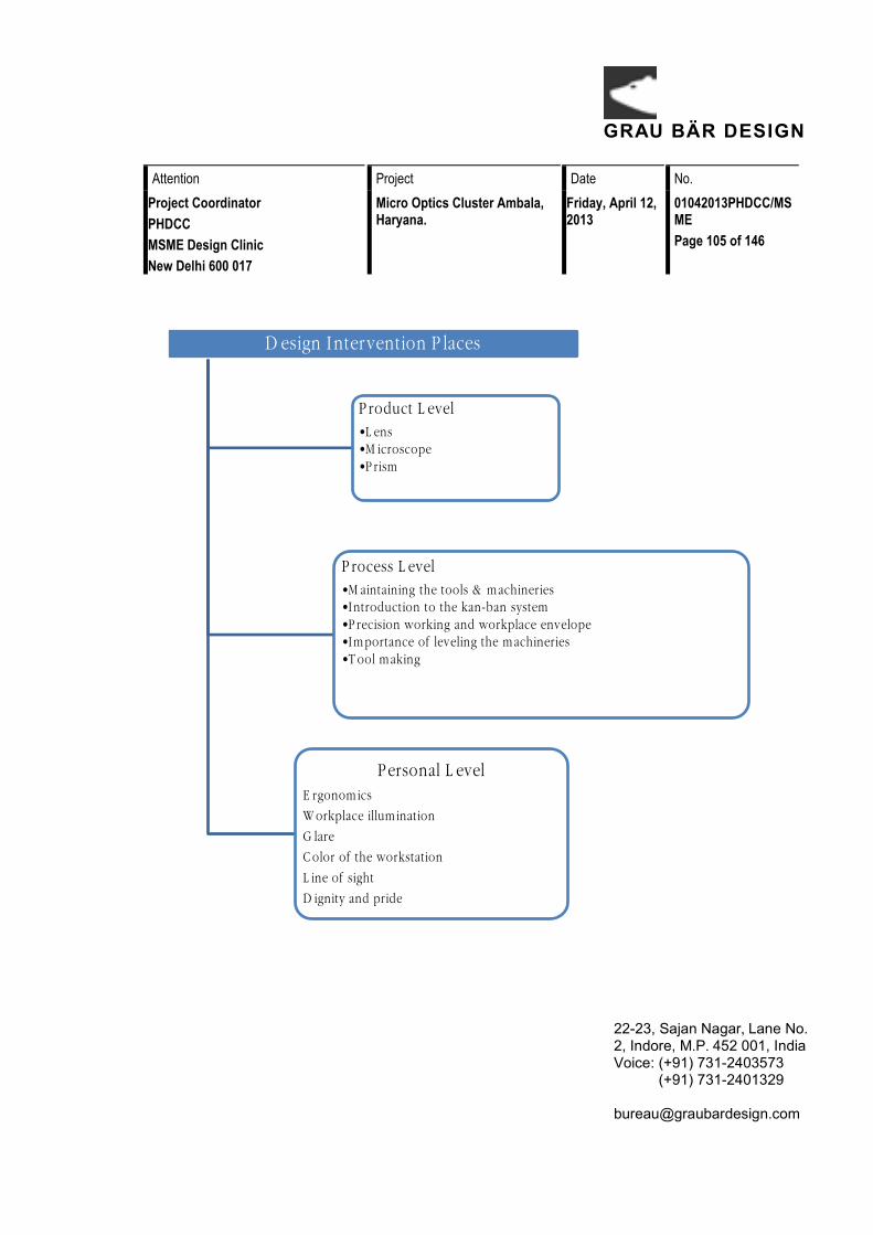
GRAU BÄR DESIGN
Attention Project Date No.Project CoordinatorPHDCCMSME Design ClinicNew Delhi 600 017
Micro Optics Cluster Ambala, Haryana.
Friday, April 12, 2013
01042013PHDCC/MSMEPage 105 of 146
22-23, Sajan Nagar, Lane No. 2, Indore, M.P. 452 001, IndiaVoice: (+91) 731-2403573 (+91) 731-2401329 [email protected]
Design Intervention Places
Product Level •Lens •Microscope •Prism
Process Level •Maintaining the tools & machineries •Introduction to the kan-ban system •Precision working and workplace envelope •Importance of leveling the machineries •Tool making
Personal Level Ergonomics
Workplace illumination
Glare
Color of the workstation
Line of sight
Dignity and pride

GRAU BÄR DESIGN
Attention Project Date No. Project Coordinator PHDCC MSME Design Clinic New Delhi 600 017
Micro Optics Cluster Ambala, Haryana.
Friday, April 12, 2013
01042013PHDCC/MSME Page 106 of 146
22-23, Sajan Nagar, Lane No. 2, Indore, M.P. 452 001, India Voice: (+91) 731-2403573 (+91) 731-2401329 [email protected]
Remedial Design & other Solutions Ergonomics
As observed during need assessment survey and also mentioned in need assessment report, one could see problems associated with sitting postures of workforces while working. When discussed in workshop, members agreed that there workforce’s face many physical problems like back ache, neck ache, etc., which is obviously sign of bad workplace ergonomics.
During workshop members were told importance of sitting postures and how good ergonomics could help their workers in improving their physical condition that in turn would help them to increase production while reducing effort in manufacturing and as well as quality of their products. Members were given the simple suggestions like,
• Adjusting the height of the chair. • Training and teaching the workforce about the importance of right Workplace ergonomics. • Taking small breaks of 2-5 minutes in an interval of one to one and a half hours.
Suggestions to Participating members
• Members were suggested to change their seating height/chairs with height adjustable chairs in next changeover.
• Members were asked to educate their workforces the importance of right way of sitting as demonstrated during workshop.
• Members were also told about, how simple change could bring the radical change in the quality as well as the quantity in the manufacturing.
These solutions were not only simple but also cost effective in long term. Members were also told the various aspects of right ergonomics, which could also help their workforces for longer working hours. They were also told importance of proper attire in workplace that they should not wear loose clothes or flowing dresses that can get entangled in rotary machines. Girls were advised to tie their hairs behind

GRAU BÄR DESIGN
Attention Project Date No. Project Coordinator PHDCC MSME Design Clinic New Delhi 600 017
Micro Optics Cluster Ambala, Haryana.
Friday, April 12, 2013
01042013PHDCC/MSME Page 107 of 146
22-23, Sajan Nagar, Lane No. 2, Indore, M.P. 452 001, India Voice: (+91) 731-2403573 (+91) 731-2401329 [email protected]
the head firmly so as to avoid a potentially dangerous situation of getting caught and pulled towards machine. Extreme caution is required while working near high speed rotating machines. They were not aware about potential danger of getting caught in rotary machines, by free discussions they were made aware and thus safe.

GRAU BÄR DESIGN
Attention Project Date No. Project Coordinator PHDCC MSME Design Clinic New Delhi 600 017
Micro Optics Cluster Ambala, Haryana.
Friday, April 12, 2013
01042013PHDCC/MSME Page 108 of 146
22-23, Sajan Nagar, Lane No. 2, Indore, M.P. 452 001, India Voice: (+91) 731-2403573 (+91) 731-2401329 [email protected]
Workplace illumination
It is of paramount importance to have good illumination in the workshop, as “optics” in its entirety, is a precision job, one should know the importance of right illumination in their workshop. This should be at least 700 to 1000 lux for precision works. To achieve good illumination one can make better use of natural light, and when it is not enough one can use in-house lightening like lamps and wall mounted lights.
During the need assessment survey, it was observed in common that many workshops did not have enough light. For some work setups, over illumination and glare was also observed which was equally bad as that may cause visual fatigue and other problems besides headache. This induces stress and increases anxiety and also reduces a person’s efficiency which often results in low quality and poor manufacturing.
Some key points were covered during this session are as under
• Good illumination (neither less nor over exposed light) helps in viewing correctly, which
automatically helps the viewer in the inspection, improving both efficiency and effectiveness as demonstrated in figure 3.
• Due to good illumination it becomes easy to find the way to the material, searching time is reduced and overall work gets streamlined.
• Since bad lightening can affect the eyesight in long as well as short run, good illumination automatically creates a good and healthy workplace environment as shown in figure 4.
It is essential to provide right light both in intensity and color spectrum for each task in the workplace. Over illumination as found in some places is energy not used correctly, it is largely wastage of electricity besides it may also cause severe health problems, such as cataract over a period of time.

GRAU BÄR DESIGN
Attention Project Date No. Project Coordinator PHDCC MSME Design Clinic New Delhi 600 017
Micro Optics Cluster Ambala, Haryana.
Friday, April 12, 2013
01042013PHDCC/MSME Page 109 of 146
22-23, Sajan Nagar, Lane No. 2, Indore, M.P. 452 001, India Voice: (+91) 731-2403573 (+91) 731-2401329 [email protected]
Figure 3. Demonstration of good level of illumination using a sample LED lighting system
Figure 4. Discussing problems of direct light.

GRAU BÄR DESIGN
Attention Project Date No. Project Coordinator PHDCC MSME Design Clinic New Delhi 600 017
Micro Optics Cluster Ambala, Haryana.
Friday, April 12, 2013
01042013PHDCC/MSME Page 110 of 146
22-23, Sajan Nagar, Lane No. 2, Indore, M.P. 452 001, India Voice: (+91) 731-2403573 (+91) 731-2401329 [email protected]
Glare
Shiny surfaces, over varnished surfaces, use of mirror, raw or exposed lights in the workshop, use of newspaper as underlay are the example of bad working practices. While working in precision it must be borne in mind that the reflectivity of the work surface influences work. It is a minute detail, which creates a lot of difference in the work. Lot of things can be improved by cutting out glare, direct as well as reflected.
During the survey it was noticed that some of the work surfaces were over shiny or using newspaper as underlay for organizing work, which is not a healthy working practice, as one cannot distinguish the quality of the lens if surface quality is acceptable or not good. Fully exposed lights are bad and counterproductive for precision work as shown in figure 5. It is very important to have no glare while viewing the lens during inspection. The minute details like scratches, called ‘sleeks’ in common parlance, cannot be detected in exposed light against unfinished surfaces. This reflects in the quality of the lens being produced.
Figure 5. an example of bad illumination.

GRAU BÄR DESIGN
Attention Project Date No. Project Coordinator PHDCC MSME Design Clinic New Delhi 600 017
Micro Optics Cluster Ambala, Haryana.
Friday, April 12, 2013
01042013PHDCC/MSME Page 111 of 146
22-23, Sajan Nagar, Lane No. 2, Indore, M.P. 452 001, India Voice: (+91) 731-2403573 (+91) 731-2401329 [email protected]
In figure we can see bad glare in the workplace. During the workshop the right way of using lights were told as shown in figures, which were an effective and efficient way instantly adaptable for working in micro optics industry.
• Use of indirect light to avoid glare helps the viewer to easily detect the errors without fatigue. • As it’s easy to see in adequate and glare free lighting, the worker feels comfortable and does not
get strain in the eye, which creates the workplace healthy. • No glare, for inspection and quality control, saves the time as it fastens the speed of finding errors
of manufacturing by revealing minutes of details. • Fewer rejections are seen in the final inspection, as most of the errors are identified and corrected
in the initial stages rather than later stages, reducing reworking.
After introducing this subject to the members, they were more curious to know what best possible changes they could do in their workshops. After telling them the solutions, some of them did it the same/next day and the results were seen effectively. As seen in figure 6 & 7 one can see the one of the easiest way to get the right amount of light in the workplace. This workbench was brought into a little change by applying a sheet on the lamp to cut out glare, reflected the light and we can see the indirect light creating more visual comfort.
Figure 6. an example of inadequate lighting for polishing and precision work.

GRAU BÄR DESIGN
Attention Project Date No. Project Coordinator PHDCC MSME Design Clinic New Delhi 600 017
Micro Optics Cluster Ambala, Haryana.
Friday, April 12, 2013
01042013PHDCC/MSME Page 112 of 146
22-23, Sajan Nagar, Lane No. 2, Indore, M.P. 452 001, India Voice: (+91) 731-2403573 (+91) 731-2401329 [email protected]
Figure 7. Examples of workstation with glare cut out.

GRAU BÄR DESIGN
Attention Project Date No. Project Coordinator PHDCC MSME Design Clinic New Delhi 600 017
Micro Optics Cluster Ambala, Haryana.
Friday, April 12, 2013
01042013PHDCC/MSME Page 113 of 146
22-23, Sajan Nagar, Lane No. 2, Indore, M.P. 452 001, India Voice: (+91) 731-2403573 (+91) 731-2401329 [email protected]
Color of the workstation Colors with a lower wave length value appear to be soothing and give a feeling of distance, whereas the colors of a higher wave length can draw attention, feel hot and appear to be nearer the observer. To make a long, rectangular room look squarer in shape, lower wavelength colors may be used for closer walls and higher wavelength colors for distant walls. In general, shop floor pillars are required to be bold in color to draw attention to their presence, for safety or for other reasons. Here, higher wavelength colors may be applied. As most setups are small (or house cum works), Similar to residential accommodation where the presence of pillars is already well known, the" cool color" applications along with aesthetic decorations may help in reducing their obtrusive character. For creating a soothing atmosphere, color harmony must be maintained.
Pink, yellow, black, purple, florescent orange or any color, which gives strain to the eye, (if seen continuously) is bad for workstations. Use of newspaper or any printed-paper, printed cloth/laminate used as background creates a lot of difficulty and lot of time is wasted in searching. It is important to have a nice, clean and good surface on the workplace like use of matte finish laminates of light gray or light blue or off-white is a good surface.
• It helps the viewer to navigate easily. • Does not create and stress when seen continuously, which automatically gives strain free working
hours. • Helps the workforces in good inspection, which again increases the quality.
Some of the simple solutions were told for right workstation, different color backgrounds were compared during the workshop and when asked from the members, they were satisfied with the problem that they were facing and were even aware of. How effectively these workstations can be improved by only using a right color sheet in the background is shown in figure 8.

GRAU BÄR DESIGN
Attention Project Date No. Project Coordinator PHDCC MSME Design Clinic New Delhi 600 017
Micro Optics Cluster Ambala, Haryana.
Friday, April 12, 2013
01042013PHDCC/MSME Page 114 of 146
22-23, Sajan Nagar, Lane No. 2, Indore, M.P. 452 001, India Voice: (+91) 731-2403573 (+91) 731-2401329 [email protected]
Figure 8. Workstation with white background.
Maintaining the tools & machineries
During the workshop the importance of maintaining the tools and machineries were emphasized. Workshops with rusted tools, machines and equipment’s making noise and problems that were not known in common were discussed and brought into concern.
• Rusted machines, has reduced life span as compared to a clean and well-maintained machine.
State of upkeep of a machine automatically reflects on the quality of product that is been produced. During the workshop, a part of a machine was re-modified to demonstrate this aspect. A polishing spindle was taken as an example, which is basically used for pitch polishing of lenses as it can be seen in Figure 9. One in the color is the old one, before restoration which had got plenty of play and vibrated during work, these vibration affects the quality of the lens which is a common problem and had never came into the consideration (as the potential cause of such issues). The other one is sand blasted to remove old paints well as mechanically restored to remove play. This simple example was used as a comparison which did not have that much of vibration.

GRAU BÄR DESIGN
Attention Project Date No. Project Coordinator PHDCC MSME Design Clinic New Delhi 600 017
Micro Optics Cluster Ambala, Haryana.
Friday, April 12, 2013
01042013PHDCC/MSME Page 115 of 146
22-23, Sajan Nagar, Lane No. 2, Indore, M.P. 452 001, India Voice: (+91) 731-2403573 (+91) 731-2401329 [email protected]
The purpose here was to demonstrate that small things make big change. People were asked to get their machineries once thoroughly cleaned and re-assembled which will help them in reducing problems as much as possible, improving quality.
Figure 9. Comparison of two spindles (one with paint is the old one and the other one is sand blasted).
Few other observations are as cited below • Slurry used for polishing (and trepanning sludge) if not cleaned from machines time to time, can
damage the machine in long run and may reduce the life of it. Below (in annexure) is a sketch demonstrating how slurry enters the severe parts of the machine, and with time they damage them from inside. Which not only reduces the life of a machine and but also reduces the quality of the lens. Solution for this problem was simple, only regular cleaning was required, which is a 15 min task of a day. Figure 10 & 11 is an example of healthy working.

GRAU BÄR DESIGN
Attention Project Date No. Project Coordinator PHDCC MSME Design Clinic New Delhi 600 017
Micro Optics Cluster Ambala, Haryana.
Friday, April 12, 2013
01042013PHDCC/MSME Page 116 of 146
22-23, Sajan Nagar, Lane No. 2, Indore, M.P. 452 001, India Voice: (+91) 731-2403573 (+91) 731-2401329 [email protected]
Figure 10. Example of good working practice.
Figure 11. A good example to maintain workshop.

GRAU BÄR DESIGN
Attention Project Date No. Project Coordinator PHDCC MSME Design Clinic New Delhi 600 017
Micro Optics Cluster Ambala, Haryana.
Friday, April 12, 2013
01042013PHDCC/MSME Page 117 of 146
22-23, Sajan Nagar, Lane No. 2, Indore, M.P. 452 001, India Voice: (+91) 731-2403573 (+91) 731-2401329 [email protected]
Figure 12. Problems being discussed in the workshop.
• Vibrations in the machine are not good sign as shown in figure 12, as these small vibrations degrade the quality of product. Dampeners or vibration suppressors are the solutions to these problems.
• Regular cleaning or cleaning of whole workshop twice in a year may improve the life of machines1
• Different grade slurries are used in the same line as shown in figure for polishing. While the machines are running, these slurries jump into each other and get mixed which are inseparable (When told, no one was aware of it) and reduces the quality of lens. Simple solution like placing a cardboard as shown in figure was provided, which was very effective, but also less expensive and easy to adapt in practice as shown in figure 13.
.
11 It was generally observed that workshops have a lot of dust, dirt and abrasive material slurry residues circulating into the system. These get into the bearing surfaces as well as cause higher rate of wear to machines, specifically in rotary components.
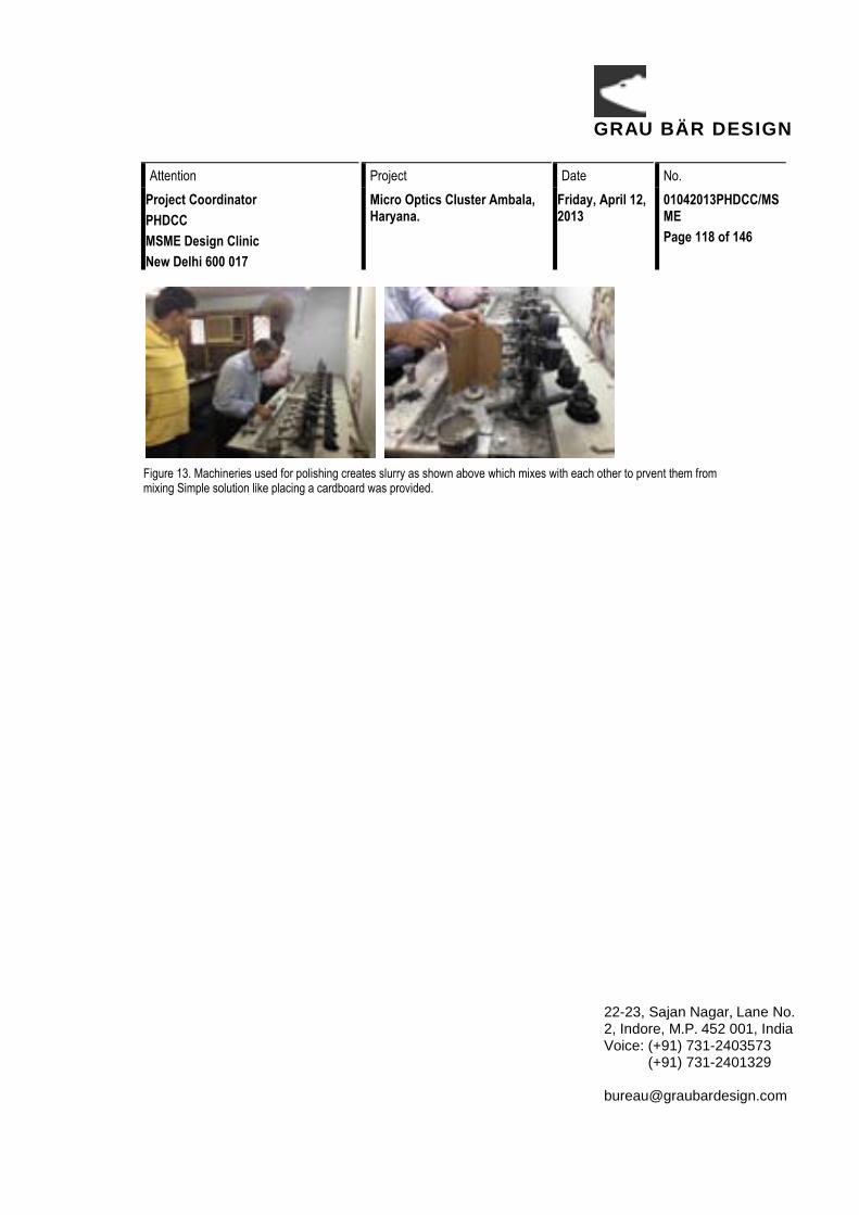
GRAU BÄR DESIGN
Attention Project Date No. Project Coordinator PHDCC MSME Design Clinic New Delhi 600 017
Micro Optics Cluster Ambala, Haryana.
Friday, April 12, 2013
01042013PHDCC/MSME Page 118 of 146
22-23, Sajan Nagar, Lane No. 2, Indore, M.P. 452 001, India Voice: (+91) 731-2403573 (+91) 731-2401329 [email protected]
Figure 13. Machineries used for polishing creates slurry as shown above which mixes with each other to prvent them from mixing Simple solution like placing a cardboard was provided.

GRAU BÄR DESIGN
Attention Project Date No. Project Coordinator PHDCC MSME Design Clinic New Delhi 600 017
Micro Optics Cluster Ambala, Haryana.
Friday, April 12, 2013
01042013PHDCC/MSME Page 119 of 146
22-23, Sajan Nagar, Lane No. 2, Indore, M.P. 452 001, India Voice: (+91) 731-2403573 (+91) 731-2401329 [email protected]
Introduction to the kan-ban system During the workshop, Mr. Vipin Sareen, Expert on lean manufacturing, introduced the process of ‘Kan-Ban’ working and through real life example showed, how it is beneficial when used in workshops. Figure14 & 15, depicts Presentation and demonstrations by the Expert.
Figure 14. Mr. Sareen explaining the kan ban system.
Figure 15. Informal discussion during tea break.

GRAU BÄR DESIGN
Attention Project Date No. Project Coordinator PHDCC MSME Design Clinic New Delhi 600 017
Micro Optics Cluster Ambala, Haryana.
Friday, April 12, 2013
01042013PHDCC/MSME Page 120 of 146
22-23, Sajan Nagar, Lane No. 2, Indore, M.P. 452 001, India Voice: (+91) 731-2403573 (+91) 731-2401329 [email protected]
Precision Working and Workplace Envelope
To reduce operational discomfort, dimensions of equipment should be designed according to the intended user's body dimensions and placed within a work space in such a manner that all the control locations are within the reach of the user. To reach easily and comfortably, each and every work accessory, these should be within operator's normal and comfortable limits of reach. Movements of the machine and material should be arranged in such a manner that they are minimal at operator’s level. Provisions may be made for him/her to be able to operate from same place while sitting, standing and/or standing in a hip rest posture, according to his/her convenience.
The designs of objects, e.g. chairs, tables, benches, storage shelves, displays, machines, and the exact layouts they require for efficient performance. Manner of their use including the functional importance of each component, the types of component links along with the work study of the intended tasks - all these should be kept in mind while arranging to make a work station.
The ideal work station and the dimensions of the equipment within it should indicate and incorporate the limits of-reach of a human operator, to ensure ease of operation and the correct outreach values, in order to avoid unnecessary obstacles.
The number and volume of the same types as well as different types of work equipment should be accommodated in the space, i.e. the physical dimensions of the work places. Passage ways and clearances within the area of the work place, i.e. considerations of physical movement, and traffic (material flow) congestion, etc., should also be considered when designing a work space.
Functional human volume
Depending on diverse work postures adopted and taking human body movements into consideration when doing specific tasks, total space is felt as personal territory and the requirements including various physical reach values, which make up the total human volume. Minute details regarding the body itself may be ignored. If a person is placed at the very centre and the placement of work components within it is obviously without any obstacle, an optimum boundary could be conceptualized for a functional individual work station. It corresponds to the central axis length from the centre bottom of both heel points in the original standing position to the tip of the vertical arm reach (including extended vertical arm reach, with a raised body on tiptoe and allowances for free space above that for overhead clearance). The total area around this axis would consist of the arm reach values of the

GRAU BÄR DESIGN
Attention Project Date No. Project Coordinator PHDCC MSME Design Clinic New Delhi 600 017
Micro Optics Cluster Ambala, Haryana.
Friday, April 12, 2013
01042013PHDCC/MSME Page 121 of 146
22-23, Sajan Nagar, Lane No. 2, Indore, M.P. 452 001, India Voice: (+91) 731-2403573 (+91) 731-2401329 [email protected]
upper, mid-level and lower reach limit lengths and heights from the floor. It also covers a posture, in the mid-sagital plane with one step forward and backwards, and on the coronal plane with one step to the right and one to the left.
The total space volume for a seated person may be considered in a similar manner as in the case of the standing posture, but only the arm reach (length) values in the "leaning positions" have to be taken, instead of the respective dimensions of the" leaning with one step" posture. The corresponding heights of the sitting posture may be considered roughly, based on the differences of values of vertical arm reach height of standing and sitting postures. While sitting cross-legged and while squatting, the space volume would be from the central axis originating at the center of the buttock end to the top of the vertical arm. Similar arm reach lengths and heights may be accounted for in leaning positions2
The value of clearance of human mobility is dependent on the various degrees of tasks to be done, whether stationary or supervisory. In some cases, the work context demands restricted movement to ensure work concentration, e.g. work with a machine where the central attention of work needs the operator to be in a fixed position like slitting glass block, trepanning, inspection etc., as shown in figure 16 and in some cases, the work contexts demand movement like polishing, block smoothing etc.
.
Figure 16(a & b) Examples where operator needs a fixed position of sitting.
2 It is observed that work attention increases in a defined work place area and is adversely affected in an undefined and or ill organized space

GRAU BÄR DESIGN
Attention Project Date No. Project Coordinator PHDCC MSME Design Clinic New Delhi 600 017
Micro Optics Cluster Ambala, Haryana.
Friday, April 12, 2013
01042013PHDCC/MSME Page 122 of 146
22-23, Sajan Nagar, Lane No. 2, Indore, M.P. 452 001, India Voice: (+91) 731-2403573 (+91) 731-2401329 [email protected]
Figure 17(a & b). Examples where operator needs movement area.
Where walking is required as shown in figure 17 and one has to keep a safe man-to-man distance, a 50th percentile span akimbo length may be allowed for a single person. Occasionally being crossed by two persons will not cause any discomfort. This does not follow the geometrical progress. Two spans of space can allow 3 - 4 persons to walk together with a little front to back alignment.
Circulation clearances raise a few questions that are not very easy to answer, and are subject to speculation and judgment. What should be the movement? How many people will walk abreast in the aisles? When one designs for special personnel, should one also consider the design of two people with mobility challenge meeting in any area? It may also be important to allow space in a work/habitat area for trainees, visitors, supervisors, assistants and other people taking into account their status, need for comfort in carrying out their respective functions, etc.
Postural considerations
Anthropometric considerations for the design of different work and habitat built environments depend on the postural adaptations required to perform varieties of tasks, sequentially. To create a user compatible optimum workspace, the layout of various articles within it must provide adequate postural comfort, while standing, sitting, semi-standing (i.e. with hip rest) lying in actual work conditions, and resting. While working, body and limb weight should be properly distributed; natural body and limb positions and an upright head must be maintained. It requires proper structural supports, if the work demands that an unusual posture be adopted. This is to avoid quick fatigue, which can adversely affect safety, induce musculo-skeletal problems, etc., pose occupation related hazards, and sometimes result in accidents (Corlett et al 1982).

GRAU BÄR DESIGN
Attention Project Date No. Project Coordinator PHDCC MSME Design Clinic New Delhi 600 017
Micro Optics Cluster Ambala, Haryana.
Friday, April 12, 2013
01042013PHDCC/MSME Page 123 of 146
22-23, Sajan Nagar, Lane No. 2, Indore, M.P. 452 001, India Voice: (+91) 731-2403573 (+91) 731-2401329 [email protected]
General work postures are seen as,
1. Sitting 2. Standing 3. Supine 4. Kneeling 5. Crawling (while finding lost objects)
In the oriental cultural context a few more work postures are also seen in use:
6. Sitting cross-legged on the floor with various leg extended positions and 7. Squatting postures.
To perform certain tasks, or a set of tasks, individuals are observed to adopt various postures at different times, and sometimes a combination of postures. The human volume required for postures 1-5 are mentioned in literature but postures 6 and 7 are inadequately reported. While designing the functional volumes of any work station and work space as shown in figure 19, these adopted postures must be analyzed according to demand of the work context and then appropriate anthropometric dimensions should be considered so that most of the postures required to perform the intended task may be accommodated.
A posture adopted without much movement and used in a work-demanding position satisfactorily without causing muscular fatigue, can be said to be a good posture. In such a posture, a man would be able to give his best efforts towards his task as shown in figure 18. His working condition should be such that if it demands a sitting position, his vertebral column should be comfortably straight, the body load should be balanced on both sides and in a standing position, the body weight should be equally distributed on both the legs, and the head should be in a comfortable position in line with the vertebral column. Postures must be adopted which would allow as many muscles as possible to come into play. Thus the muscles would be more efficient and skillful, and would perform the task well. Dr. Vyas explaining the importance of precision work and how some changes may bring upon the quality.

GRAU BÄR DESIGN
Attention Project Date No. Project Coordinator PHDCC MSME Design Clinic New Delhi 600 017
Micro Optics Cluster Ambala, Haryana.
Friday, April 12, 2013
01042013PHDCC/MSME Page 124 of 146
22-23, Sajan Nagar, Lane No. 2, Indore, M.P. 452 001, India Voice: (+91) 731-2403573 (+91) 731-2401329 [email protected]
Figure 18. A typical Sitting posture of a milling machine operator.
Figure 19(a & b). A good example of work space envelope.
Figure 20. Dr. Vyas telling the importance of precision work.
Importance of leveling the machineries

GRAU BÄR DESIGN
Attention Project Date No. Project Coordinator PHDCC MSME Design Clinic New Delhi 600 017
Micro Optics Cluster Ambala, Haryana.
Friday, April 12, 2013
01042013PHDCC/MSME Page 125 of 146
22-23, Sajan Nagar, Lane No. 2, Indore, M.P. 452 001, India Voice: (+91) 731-2403573 (+91) 731-2401329 [email protected]
As discussed earlier placing machineries in right place and on plane surface, during workshop the importance of leveling meter were told and how this tool could help them, problems and solutions were discussed with live demonstration as shown in figure 21 & 22.
Figure 21. Demonstration of leveling meter.
Figure 22. Demonstration of how leveling meter works.

GRAU BÄR DESIGN
Attention Project Date No. Project Coordinator PHDCC MSME Design Clinic New Delhi 600 017
Micro Optics Cluster Ambala, Haryana.
Friday, April 12, 2013
01042013PHDCC/MSME Page 126 of 146
22-23, Sajan Nagar, Lane No. 2, Indore, M.P. 452 001, India Voice: (+91) 731-2403573 (+91) 731-2401329 [email protected]
Line of sight The total shape of the room, the nature of the intended work to be done within that, and the shapes, sizes, positioning of fittings, etc. which contribute in creating interior visual and climatic environment, e.g. Illumination, glare, noise, vibration, motion, heat. Humidity, ventilation etc. all affect human performance and must be given due importance.
Covered ceilings in small spaces are prone to accumulate substances like toxic gases and displeasing odors. Such spaces however, in rest and washrooms should not be fully covered and if they have to be covered for some reason, exhaust fans should be fixed, failing which, people are repelled by the odors and will not go near such places, etc. The unclean conditions gradually discourage proper use. This may be avoided by proper design arrangements.
Illumination plays its own role in space perception. The positioning of illumination installations and natural light sources such as windows, etc. and the intensity of light and glare modify utilization of the work space. Less light makes people move nearer to the center of attention, and adopt postures which could induce health problems. Darkness makes a given space appear psychologically closer than a bright one. For ease of operation and efficiency, adequate general lighting and the required localized installation of light sources are necessary. The proper application of these would ensure proper utilization of a given space and equipment, that has been designed with due respect to natural daylight. For getting efficient and evenness of general illumination application of colors (with due emphasis on color reflectance values), on the walls, floor and other surfaces, may be given due consideration.
The distance between the actual work spot and the worker increases if the work spot generates heat, e.g. in case of a foundry or where furnaces are used. Climatic or seasonal variations also influence this. Hence, adverse environmental factors and their sources should be given due consideration, while designing such workspaces.
GRAU BÄR DESIGN
Attention Project Date No. Project Coordinator PHDCC MSME Design Clinic New Delhi 600 017
Micro Optics Cluster Ambala, Haryana.
Friday, April 12, 2013
01042013PHDCC/MSME Page 127 of 146
22-23, Sajan Nagar, Lane No. 2, Indore, M.P. 452 001, India Voice: (+91) 731-2403573 (+91) 731-2401329 [email protected]
Dignity and pride
“It is important to have dignity and pride in work we do”
During the survey it was common to find that owners and proprietors had general complains for the workforces, a feeling that was equally reciprocal in nature. This was obvious that no one took pride in what they were working. This is because they did not like workplace and working environment. Small things make a big change, during the survey as discussed about various known irritants that impede a feeling of wellbeing and therefore contribute to such feelings.
• Lighting
• Ventilation (HVAC)
• Cleanliness (free from dust, suspended particles and malodors)
• Proper Seating
• Hydration and periodic breaks
Tool making During the survey Quick Tool making was demonstrated by taking live examples from the shop floor as shown in figure 23(a to f).
Simple techniques were effectively used for enhancing grips and facilitate polishing of extremely small sized lenses.
Some suggestions that were made are reproduced as it is for reference. The sketches bridged the gap of language and people with little understanding of formal English were able to make the changes at their workshops, simply by referring to hand drawn sketches.

GRAU BÄR DESIGN
Attention Project Date No. Project Coordinator PHDCC MSME Design Clinic New Delhi 600 017
Micro Optics Cluster Ambala, Haryana.
Friday, April 12, 2013
01042013PHDCC/MSME Page 128 of 146
22-23, Sajan Nagar, Lane No. 2, Indore, M.P. 452 001, India Voice: (+91) 731-2403573 (+91) 731-2401329 [email protected]
Figure 23 (a to f). Figures demonstrating how one can improve their tools with some modifications.

GRAU BÄR DESIGN
Attention Project Date No. Project Coordinator PHDCC MSME Design Clinic New Delhi 600 017
Micro Optics Cluster Ambala, Haryana.
Friday, April 12, 2013
01042013PHDCC/MSME Page 129 of 146
22-23, Sajan Nagar, Lane No. 2, Indore, M.P. 452 001, India Voice: (+91) 731-2403573 (+91) 731-2401329 [email protected]
Annexure
Scanned imaged of explanations and spot problem solving during the workshop for future references.
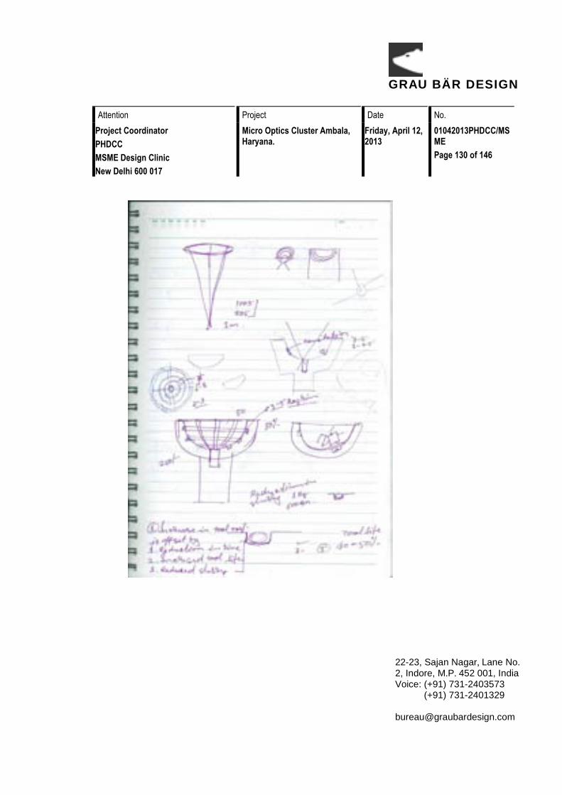
GRAU BÄR DESIGN
Attention Project Date No. Project Coordinator PHDCC MSME Design Clinic New Delhi 600 017
Micro Optics Cluster Ambala, Haryana.
Friday, April 12, 2013
01042013PHDCC/MSME Page 130 of 146
22-23, Sajan Nagar, Lane No. 2, Indore, M.P. 452 001, India Voice: (+91) 731-2403573 (+91) 731-2401329 [email protected]

GRAU BÄR DESIGN
Attention Project Date No. Project Coordinator PHDCC MSME Design Clinic New Delhi 600 017
Micro Optics Cluster Ambala, Haryana.
Friday, April 12, 2013
01042013PHDCC/MSME Page 131 of 146
22-23, Sajan Nagar, Lane No. 2, Indore, M.P. 452 001, India Voice: (+91) 731-2403573 (+91) 731-2401329 [email protected]

GRAU BÄR DESIGN
Attention Project Date No. Project Coordinator PHDCC MSME Design Clinic New Delhi 600 017
Micro Optics Cluster Ambala, Haryana.
Friday, April 12, 2013
01042013PHDCC/MSME Page 132 of 146
22-23, Sajan Nagar, Lane No. 2, Indore, M.P. 452 001, India Voice: (+91) 731-2403573 (+91) 731-2401329 [email protected]

GRAU BÄR DESIGN
Attention Project Date No. Project Coordinator PHDCC MSME Design Clinic New Delhi 600 017
Micro Optics Cluster Ambala, Haryana.
Friday, April 12, 2013
01042013PHDCC/MSME Page 133 of 146
22-23, Sajan Nagar, Lane No. 2, Indore, M.P. 452 001, India Voice: (+91) 731-2403573 (+91) 731-2401329 [email protected]

GRAU BÄR DESIGN
Attention Project Date No. Project Coordinator PHDCC MSME Design Clinic New Delhi 600 017
Micro Optics Cluster Ambala, Haryana.
Friday, April 12, 2013
01042013PHDCC/MSME Page 134 of 146
22-23, Sajan Nagar, Lane No. 2, Indore, M.P. 452 001, India Voice: (+91) 731-2403573 (+91) 731-2401329 [email protected]

GRAU BÄR DESIGN
Attention Project Date No. Project Coordinator PHDCC MSME Design Clinic New Delhi 600 017
Micro Optics Cluster Ambala, Haryana.
Friday, April 12, 2013
01042013PHDCC/MSME Page 135 of 146
22-23, Sajan Nagar, Lane No. 2, Indore, M.P. 452 001, India Voice: (+91) 731-2403573 (+91) 731-2401329 [email protected]

GRAU BÄR DESIGN
Attention Project Date No. Project Coordinator PHDCC MSME Design Clinic New Delhi 600 017
Micro Optics Cluster Ambala, Haryana.
Friday, April 12, 2013
01042013PHDCC/MSME Page 136 of 146
22-23, Sajan Nagar, Lane No. 2, Indore, M.P. 452 001, India Voice: (+91) 731-2403573 (+91) 731-2401329 [email protected]

GRAU BÄR DESIGN
Attention Project Date No. Project Coordinator PHDCC MSME Design Clinic New Delhi 600 017
Micro Optics Cluster Ambala, Haryana.
Friday, April 12, 2013
01042013PHDCC/MSME Page 137 of 146
22-23, Sajan Nagar, Lane No. 2, Indore, M.P. 452 001, India Voice: (+91) 731-2403573 (+91) 731-2401329 [email protected]
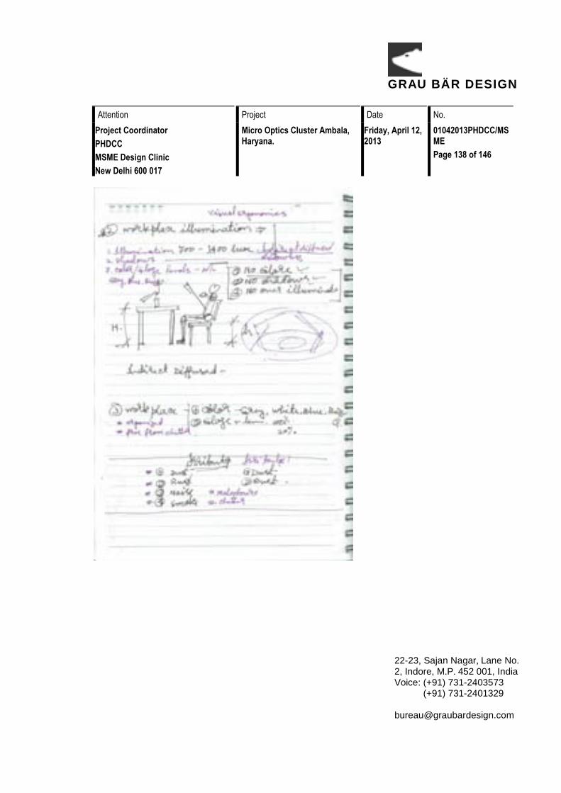
GRAU BÄR DESIGN
Attention Project Date No. Project Coordinator PHDCC MSME Design Clinic New Delhi 600 017
Micro Optics Cluster Ambala, Haryana.
Friday, April 12, 2013
01042013PHDCC/MSME Page 138 of 146
22-23, Sajan Nagar, Lane No. 2, Indore, M.P. 452 001, India Voice: (+91) 731-2403573 (+91) 731-2401329 [email protected]

GRAU BÄR DESIGN
Attention Project Date No. Project Coordinator PHDCC MSME Design Clinic New Delhi 600 017
Micro Optics Cluster Ambala, Haryana.
Friday, April 12, 2013
01042013PHDCC/MSME Page 139 of 146
22-23, Sajan Nagar, Lane No. 2, Indore, M.P. 452 001, India Voice: (+91) 731-2403573 (+91) 731-2401329 [email protected]

GRAU BÄR DESIGN
Attention Project Date No. Project Coordinator PHDCC MSME Design Clinic New Delhi 600 017
Micro Optics Cluster Ambala, Haryana.
Friday, April 12, 2013
01042013PHDCC/MSME Page 140 of 146
22-23, Sajan Nagar, Lane No. 2, Indore, M.P. 452 001, India Voice: (+91) 731-2403573 (+91) 731-2401329 [email protected]

GRAU BÄR DESIGN
Attention Project Date No. Project Coordinator PHDCC MSME Design Clinic New Delhi 600 017
Micro Optics Cluster Ambala, Haryana.
Friday, April 12, 2013
01042013PHDCC/MSME Page 141 of 146
22-23, Sajan Nagar, Lane No. 2, Indore, M.P. 452 001, India Voice: (+91) 731-2403573 (+91) 731-2401329 [email protected]

GRAU BÄR DESIGN
Attention Project Date No. Project Coordinator PHDCC MSME Design Clinic New Delhi 600 017
Micro Optics Cluster Ambala, Haryana.
Friday, April 12, 2013
01042013PHDCC/MSME Page 142 of 146
22-23, Sajan Nagar, Lane No. 2, Indore, M.P. 452 001, India Voice: (+91) 731-2403573 (+91) 731-2401329 [email protected]
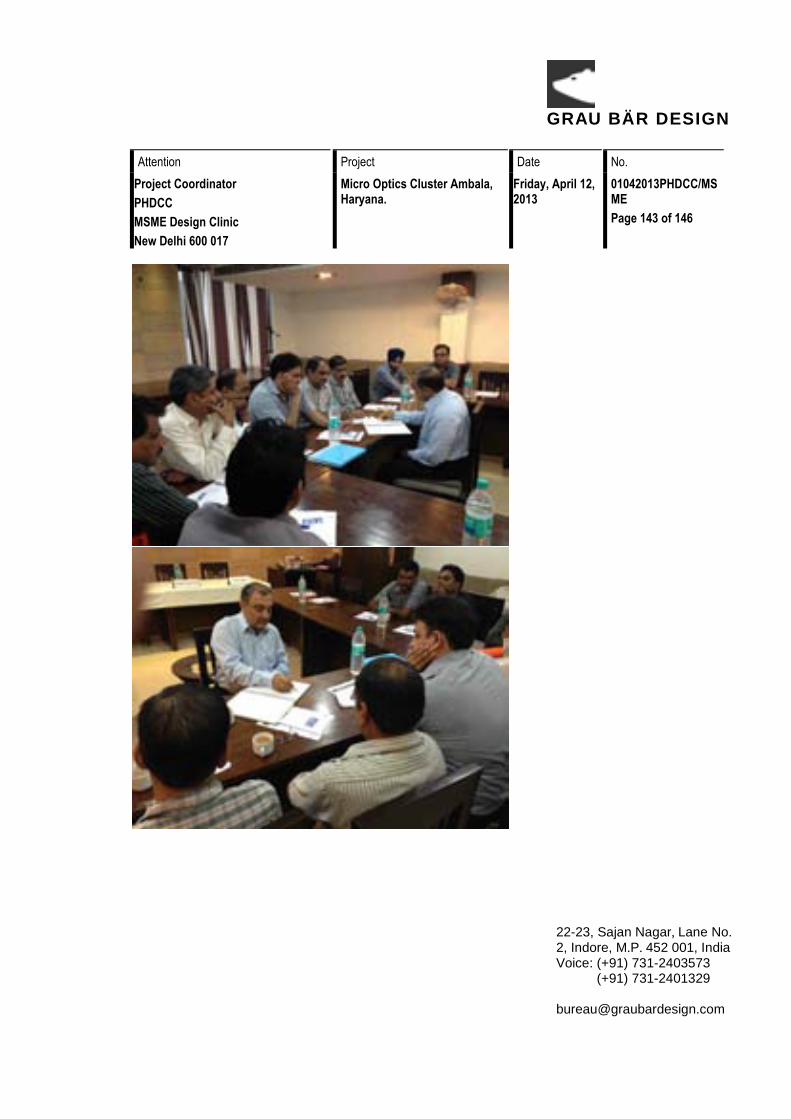
GRAU BÄR DESIGN
Attention Project Date No. Project Coordinator PHDCC MSME Design Clinic New Delhi 600 017
Micro Optics Cluster Ambala, Haryana.
Friday, April 12, 2013
01042013PHDCC/MSME Page 143 of 146
22-23, Sajan Nagar, Lane No. 2, Indore, M.P. 452 001, India Voice: (+91) 731-2403573 (+91) 731-2401329 [email protected]

GRAU BÄR DESIGN
Attention Project Date No. Project Coordinator PHDCC MSME Design Clinic New Delhi 600 017
Micro Optics Cluster Ambala, Haryana.
Friday, April 12, 2013
01042013PHDCC/MSME Page 144 of 146
22-23, Sajan Nagar, Lane No. 2, Indore, M.P. 452 001, India Voice: (+91) 731-2403573 (+91) 731-2401329 [email protected]

GRAU BÄR DESIGN
Attention Project Date No. Project Coordinator PHDCC MSME Design Clinic New Delhi 600 017
Micro Optics Cluster Ambala, Haryana.
Friday, April 12, 2013
01042013PHDCC/MSME Page 145 of 146
22-23, Sajan Nagar, Lane No. 2, Indore, M.P. 452 001, India Voice: (+91) 731-2403573 (+91) 731-2401329 [email protected]

GRAU BÄR DESIGN
Attention Project Date No. Project Coordinator PHDCC MSME Design Clinic New Delhi 600 017
Micro Optics Cluster Ambala, Haryana.
Friday, April 12, 2013
01042013PHDCC/MSME Page 146 of 146
22-23, Sajan Nagar, Lane No. 2, Indore, M.P. 452 001, India Voice: (+91) 731-2403573 (+91) 731-2401329 [email protected]
Important web references for books and tools Links for precision optical glass working http://www.abebooks.com/9780333350416/Precision-Optical-Glassworking-Manual-Manufacture-0333350413/plp http://www.amazon.com/Precision-Optical-Glassworking-W-Zschommler/dp/0333350413 Links for Indian anthropometric dimensions http://www.bookshopofindia.com/search.asp?action1=default&bookid=39088 http://books.google.co.in/books/about/Indian_anthropometric_dimensions_for_erg.html?id=koyAAAAAMAAJ Tools http://www.stanleyblackanddecker.com/ http://www.stanleytools.com/ http://www.blackanddecker.com/
Bibliography Chakrabarti, Debkumar. Indian Anthropometric Dimentions For Ergonomic Design Practice. ahmedabad: National Institute od Design, 1997.