near net shape casting through investment, die and
TRANSCRIPT
CAFP - 2008 Special Metal Casting and Forming Processes
NEAR NET SHAPE CASTING THROUGH INVESTMENT, DIE AND CENTRIFUGAL CASTING
D. Mandal National Metallurgical Laboratory, Jamshedpur 831007
e-mail: [email protected]
INTRODUCTION
Casting is basically pouring of the molten metal into a cavity or mould, which is in proper shape. Casting was known by human-being since the 4th century B. C. Today it is nearly impossible to design anything that cannot be cast by means of one or more of the available casting processes. However, as with other manufacturing processes, best results and economy can be achieved if the designer understands the various casting processes and adapts designs so as to use the process most efficiently.
The cost of any part increases in directly proportion to the preciseness ofits dimensional tolerance requirements. This is true of castings, as well as fabricated and machined parts. The investment castings are designed to minimize the cost of producing close tolerance parts. While careful machining can achieve closer tolerances than available in an investment casting, a critical design review will often permit minor expansion of tolerances, undercuts, blind holes, etc. to allow the higher production yields and lower piece costs possible with investment castings. If closer cast tolerances are necessary, the machining required on an investment casting will still be substantially less than on conventional cast or fabricated pieces.
With the current emphasis on reducing materials consumption through virtually net shape processing and the demand for higher-strength parts for weight savings, the emergence of die casting as a production process has given materials and process engineers a new alternative to the traditional approaches of casting. By pressurizing liquid metals while they solidify, near-net shape can be achieved in soundfully dense castings. Improved mechanical properties are additional advantages. The microstructural refinement and integrity of die cast products are desirable for many critical applications.
Many castings are produced in which there is no possible way to eliminate microshrinkage, situations in which the rate of solidification and the tortuosity of the paths available around the
1
CAFP - 2008 Special Metal Casting and Forming Processes
dendrites is such that fluid flow to feed shrinkage is nearly impossible. In these instances the casting is then left with the microshrinkage as inevitable defects, which can significantly reduce the fatigue properties and ductility of these materials. In the die casting process the press force effectively squeezes out the shrinkage porosity that would not be removed by risering practice, the movable punch exerting a force on the casting while it is solidifying.
Centrifugal casting may employ permanent moulds similar to those used for chill casting, or sand moulds. Its purpose is to obtain by centrifugal force a denser casting and consequently a casting more reliable from the viewpoint of soundness. Centrifugal casting has greater reliability than static castings. They are relatively free from gas and shrinkage porosity.
PRECISION CASTING (INVESTMENT CASTING)
Precision castings are being used in industry because the casting process offers many benefits over conventional casting, including design freedom, close tolerances, better surface finishing, and savings in machining time, reproductivibility, and assembly savings. Investment castings are essentially cast to size, thus decreasing the amount of machining required. Infinite choice of alloys and design flexibility for internal and external configurations is seen as a plus point. The Investment casting advantage gives the ability to design and produce parts not possible with traditional machining processes.
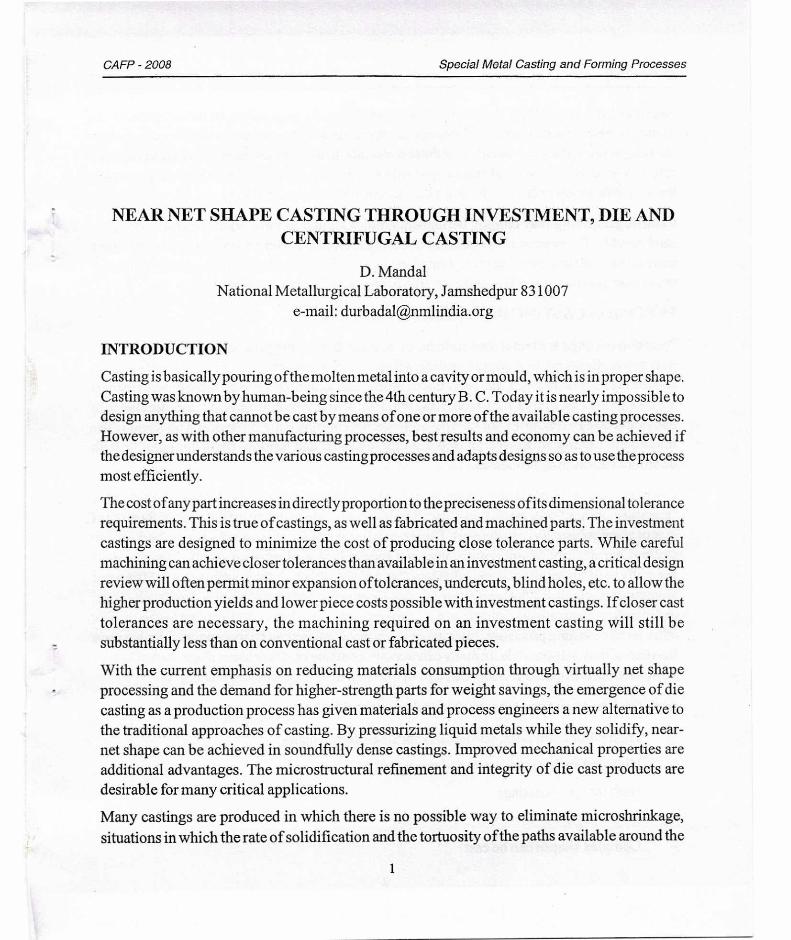
Casting processes in which the pattern is used only once are variously referred to as "lost-wax" or "precision-casting" processes. In any case they involve making a pattern ofthe desired form out of wax or plastics (usually polystyrene). The process is suitable for series production of high quality castings particularly of aluminium, steel and special high performance alloys. The process is generally used for small castings, often less than 500gm, although steel castings up to 3 00kg and aluminium castings of 30kg are being produced. Compared to other casting processes such as sand or die casting, investment casting is an expensive process, but it has versatility approached by few other metals forming processes. Intricate or re-entrant contours can be incorporated so that great freedom of design is possible. In many cases components are cast near to net shape so that little or no machining is necessary. Different steps of investment casting are shown in Fig. 1.
Specific characteristics of investment casting are as follows:
- High production rates, particularly for small components
- High dimensional accuracy and consistency
- High integrity castings
- Extremely good surface finish obtained
- Complex shapes can be cast
2
Slurriy. coating Contpkted tuold
(h) Autoclaved
Heat Heat
(0
N4Oltell ‘Va X or
.I'attern tnettout Pouicin
Mold to nutIce pattern,
P. (:.1) • b) (c)
.1.
Injection ‘vax or pattern
Wax paitern
pattern Pattern :...tssenihly
CAFP - 2008
Special Metal Casting and Forming Processes
Fig. 1(a) : Investment casting process
- Long or short runs can be accommodated
- Machining can be eliminated
- Minimum shot blast and grinding needed
- Almost any alloy can be cast
- Environmentally good
- Specialised equipment needed
- The process is expensive because costly refractories and binders are used and many operations are needed to make a mould
- Because ofthe exceptional surface finish possible and expected, minute defects can cause rejection of castings and scrap rates can be high.
3
CAFP - 2008 Special Metal Casting and Forming Processes
Investment casting process
Pattern production
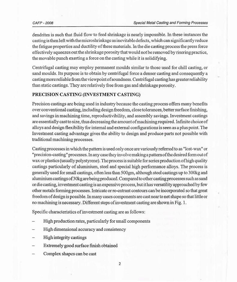
The process begins with production of a wax pattern. A metal die is normally used to produce the pattern, now almost universally of wax. The injection dies are made from materials such as aluminium, steel or duralumin and brass. Larger parts are made in sections from different tools and then wax assembled. Once the die is made, countless disposable patterns can be produced. Wax is injected into the die in a pasty (Semi-Solid) or liquid state. The type of wax injection machines used dictates the condition ofthe wax. Some pattern injection machines are completely automatic and complex parts can be produced without difficulty. Th.e majority ofwax machines are manually operated.
Fig. 1(b) : Wax Pattern Production
However alternate pattern materials such as plastic, urea or polystyrene can be used. Wax blends are the major materials used in investment casting. The blends are of synthetic, animal and vegetable waxes, with various resin and rosin additives. Fillers are used to reduce shrinkage and to change the stabilization characteristics ofthe waxes. They range from 10-40% ofthe wax by weight. The way pattern wax is handled during the melting, conditioning and injection stages of pre-pattern production will directly reflect the quality of wax patterns produced in the wax room. Proper handling methods can eliminate a multitude of wax pattern defects for the investment casting foundries.
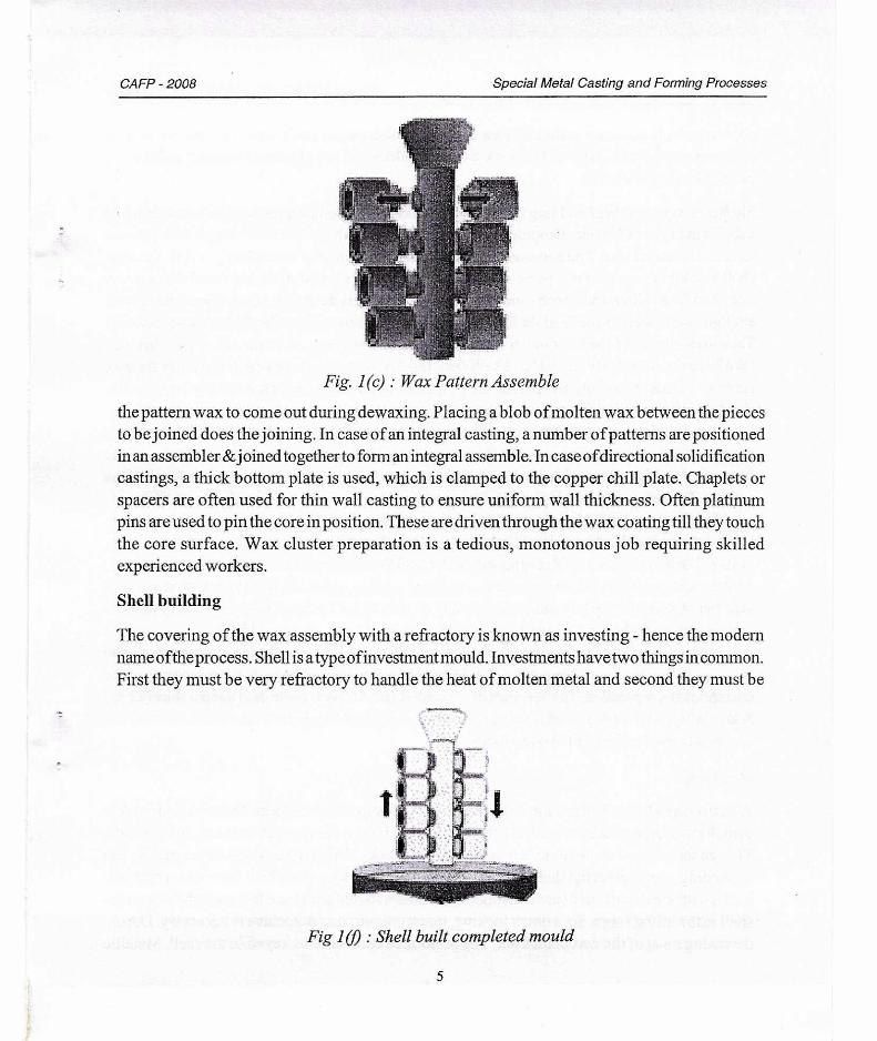
Wax pattern assembly
A numbers ofwax patterns should be joined to the runner or riser system or the pouring cup with central stem to prepare a wax tree or cluster. The runner or riser system components are made of a lower melting wax. The idea is that they should melt first & provide a readymade passage for
4
CAFP - 2008 Special Metal Casting and Forming Processes
Fig. 1(c) : Wax Pattern Assemble
the pattern wax to come out during dewaxing. Placing a blob ofmolten wax between the pieces to be joined does the joining. In case of an integral casting, a number of patterns are positioned in an assembler & joined together to form an integral assemble. In case of directional solidification castings, a thick bottom plate is used, which is clamped to the copper chill plate. Chaplets or spacers are often used for thin wall casting to ensure uniform wall thickness. Often platinum pins are used to pin the core in position. These are driven through the wax coating till they touch the core surface. Wax cluster preparation is a tedious, monotonous job requiring skilled experienced workers.
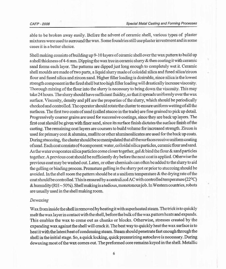
Shell building
The covering of the wax assembly with a refractory is known as investing - hence the modern name oftheprocess. Shell is a type ofinvestment mould. Investments have two things in common. First they must be very refractory to handle the heat of molten metal and second they must be
Fig : Shell built completed mould
5
CAFP - 2008 Special Metal Casting and Forming Processes
able to be broken away easily. Before the advent of ceramic shell, various types of plaster mixtures were used to surround the wax. Some foundries still use plaster investment and in some cases it is a better choice.
Shell making consists ofbuilding up 9-10 layers of ceramic shell over the wax pattern to build up a shell thickness of4-6 mm. Dipping the wax tree in ceramic slurry & then coating it with ceramic sand forms each layer. The patterns are dipped just long enough to completely wet it. Ceramic shell moulds are made of two parts, a liquid slurry made of coloidal silica and fused silica/zircon flour and fused silica and zircon sand. Higher filler loading is desirable, since silica is the lowest strength component in the fired shell but too high filler loading will drastically increase viscosity. Thorough mixing of the flour into the slurry is necessary to bring down the viscosity. This may take 24 hours. The slurry should have sufficient fluidity, so that it spreads uniformly over the wax surface. Viscosity, density and pH are the properties of the slurry, which should be periodically checked and controlled. The operator should rotate the cluster to ensure uniform wetting of all the surfaces. The first two coats of sand (called stucoo in the trade) are fine grained to pick up detail. Progressively coarser grains are used for successive coatings, since they are back up layers. The first coat should be given with finer sand, since its surface finish dictates the surface finish of the casting. The remaining coat layers are coursers to build volume for increased strength. Zircon is used for primary coat & alumina, mullite or other aluminosilicates are used for the back up coats. During stuccoing, the cluster should be so manipulated that all the surfaces receive uniform coating of sand. Each coat consists of4 component: water, colloidal silica particles, ceramic flour and sand. As the water evaporates silica particles come closer together, gel & bind the flour & sand particles together. A previous coat should be sufficiently dry before the next coat is applied. Otherwise the previous coat maybe washed out. Latex, or other chemicals can often be added to the slurry to aid the gelling or binding process. Premature gelling in the slurry pot or prior to stuccoing should be avoided. In the shell room the pattern should be at a uniform temperature & the drying rate of the coat should be controlled. This is ensured by a centralized AC with controlled temperature (22°C) & humudity (RH — 50%). Shell making is a tedious, monotonous job. In Western countries, robots are usually used in the shell making room.
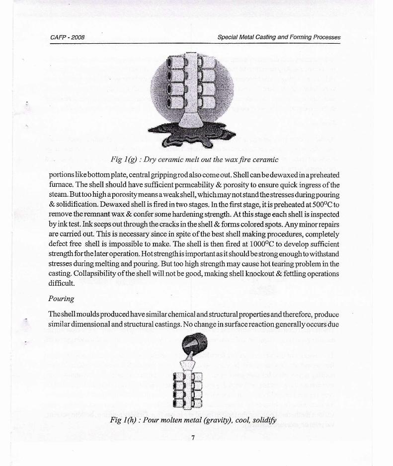
Dewaxing
Wax from inside the shell is removed by heating it with superheated steam. The trick is to quickly melt the wax layer in contact with the shell, before the bulk of the wax pattern heats and expands. This enables the wax to come out as chunks or blocks. Otherwise, stresses created by the expanding wax against the shell will crack it. The best way to quickly heat the wax surface is to heat it with the latent heat of condensing steam. Steam should penetrate fast enough through the shell in the initial stage. So, a quick locking, quick pressurizing autoclave is necessary. During dewaxing most of the wax comes out. The preformed core remains keyed in the shell. Metallic
6
CAFP - 2008 Special Metal Casting and Forming Processes
Fig 1(g) : Dry ceramic melt out the wax fire ceramic
portions like bottom plate, central gripping rod also come out. Shell can be dewaxed in a preheated furnace. The shell should have sufficient permeability & porosity to ensure quick ingress of the steam. But too high a porosity means a weak shell, which may not stand the stresses during pouring & solidification. Dewaxed shell is fired in two stages. In the first stage, it is preheated at 500°C to remove the remnant wax & confer some hardening strength. At this stage each shell is inspected by ink test. Ink seeps out through the cracks in the shell & forms colored spots. Any minor repairs are carried out. This is necessary since in spite of the best shell making procedures, completely defect free shell is impossible to make. The shell is then fired at 1000°C to develop sufficient strength for the later operation. Hot strength is important as it should be strong enough to withstand stresses during melting and pouring. But too high strength may cause hot tearing problem in the casting. Collapsibility of the shell will not be good, making shell knockout & fettling operations difficult.
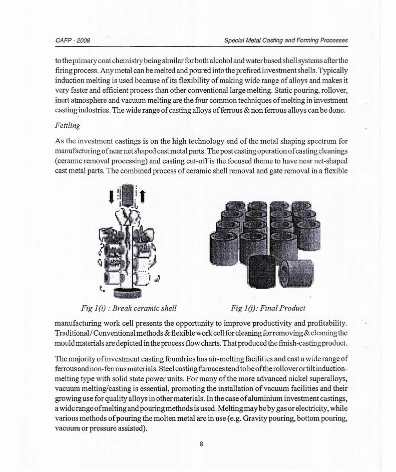
Pouring
The shell moulds produced have similar chemical and structural properties and therefore, produce similar dimensional and structural castings. No change in surface reaction generally occurs due
Fig 1(h) : Pour molten metal (gravity), cool, solidify
7
CAFP - 2008 Special Metal Casting and Forming Processes
to the primary coat chemistry being similar for both alcohol and water based shell systems after the firing process. Any metal can be melted and poured into the prefired investment shells. Typically induction melting is used because of its flexibility of making wide range of alloys and makes it very faster and efficient process than other conventional large melting. Static pouring, rollover, inert atmosphere and vacuum melting are the four common techniques of melting in investment casting industries. The wide range of casting alloys of ferrous & non ferrous alloys can be done.
Fettling
As the investment castings is on the high technology end of the metal shaping spectrum for manufacturing of near net shaped cast metal parts. The post casting operation of casting cleanings (ceramic removal processing) and casting cut-off is the focused theme to have near net-shaped cast metal parts. The combined process of ceramic shell removal and gate removal in a flexible
Fig 1(i) : Break ceramic shell Fig 10: Final Product
manufacturing work cell presents the opportunity to improve productivity and profitability. Traditional / Conventional methods & flexible work cell for cleaning for removing & cleaning the mould materials are depicted in the process flow charts. That produced the finish-casting product.
The majority of investment casting foundries has air-melting facilities and cast a wide range of ferrous and non-ferrous materials. Steel casting furnaces tend to be of the rollover or tilt induction-melting type with solid state power units. For many of the more advanced nickel superalloys, vacuum melting/casting is essential, promoting the installation of vacuum facilities and their growing use for quality alloys in other materials. In the case of aluminium investment castings, a wide range ofmelting and pouring methods is used. Melting maybe by gas or electricity, while various methods of pouring the molten metal are in use (e.g. Gravity pouring, bottom pouring, vacuum or pressure assisted).
8
CAFP - 2008 Special Metal Casting and Forming Processes
PERMANENT-MOLD CASTING PROCESSES
The process utilizes a metal casting die in conjunction with metal or sand cores. Molten metal is introduced at the top of the mould that has two or more parts, using only the force of gravity. After solidification, the mould is opened and the casting ejected. The mould is reassembled and the cycle is repeated. The moulds are either metal or graphite and, consequently, most permanent-mould castings are restricted to lower melting point nonferrous metals and alloys.
DIE CASTING
Advantage of Die casting than other Casting Process
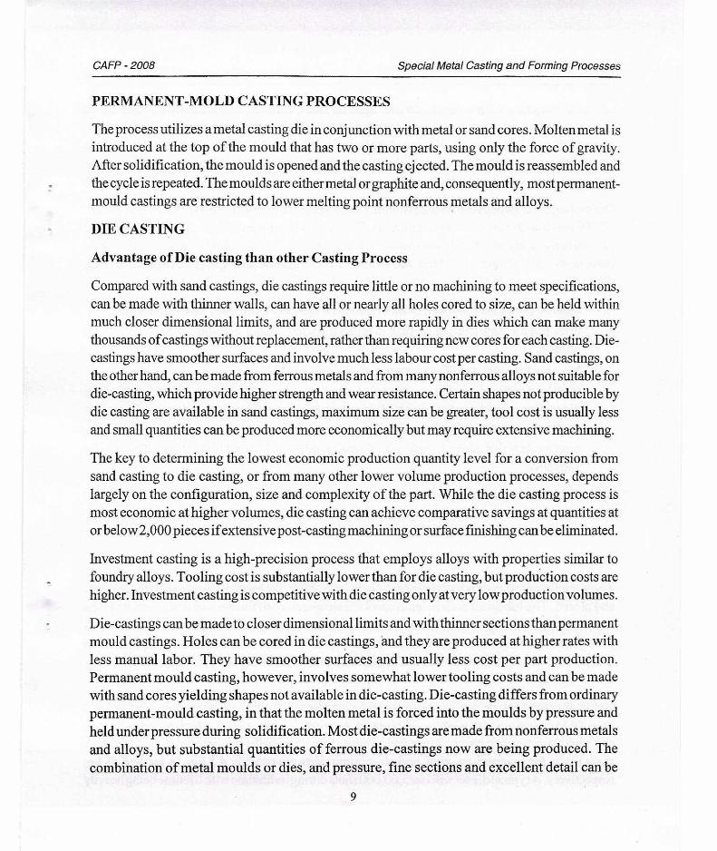
Compared with sand castings, die castings require little or no machining to meet specifications, can be made with thinner walls, can have all or nearly all holes cored to size, can be held within much closer dimensional limits, and are produced more rapidly in dies which can make many thousands of castings without replacement, rather than requiring new cores for each casting. Die-castings have smoother surfaces and involve much less labour cost per casting. Sand castings, on the other hand, can be made from ferrous metals and from many nonferrous alloys not suitable for die-casting, which provide higher strength and wear resistance. Certain shapes not producible by die casting are available in sand castings, maximum size can be greater, tool cost is usually less and small quantities can be produced more economically but may require extensive machining.
The key to determining the lowest economic production quantity level for a conversion from sand casting to die casting, or from many other lower volume production processes, depends largely on the configuration, size and complexity of the part. While the die casting process is most economic at higher volumes, die casting can achieve comparative savings at quantities at or below 2,000 pieces if extensive post-casting machining or surface finishing can be eliminated.
Investment casting is a high-precision process that employs alloys with properties similar to foundry alloys. Tooling cost is substantially lower than for die casting, but production costs are higher. Investment casting is competitive with die casting only at very low production volumes.
Die-castings can be made to closer dimensional limits and with thinner sections than permanent mould castings. Holes can be cored in die castings, and they are produced at higher rates with less manual labor. They have smoother surfaces and usually less cost per part production. Permanent mould casting, however, involves somewhat lower tooling costs and can be made with sand cores yielding shapes not available in die-casting. Die-casting differs from ordinary permanent-mould casting, in that the molten metal is forced into the moulds by pressure and held under pressure during solidification. Most die-castings are made from nonferrous metals and alloys, but substantial quantities of ferrous die-castings now are being produced. The combination of metal moulds or dies, and pressure, fine sections and excellent detail can be
9
CAFP - 2008 Special Metal Casting and Forming Processes
achieved, together with long mould life. Special zinc-, copper-, and aluminium-base alloys suitable for die-casting have been developed which have excellent properties, thereby contributing to the very extensive use of the process. Because die-casting dies usually are made from hardened tool steel, they are expensive to make. In addition, the die sections must contain knockout pins, which eject the casting.
Die casting is the process of forcing molten metal under high pressure of 10 - 210 Mpa (1,450 -30,500) psi into the cavities of steel moulds. This results in a more uniform part, generally good surface finish and good dimensional accuracy, as good as 0.2 % of casting dimension. For many parts, post-machining can be totally eliminated, or very light machining may berequired to bring dimensions to size. In fact, the process lends itself to making any metal part that:
- must be precise (dimensions plus or minus as little as 50 gm--over short distances),
-
must have a very smooth surface that can be bright plated without prior polishing and buffing,
- has very thin sections (like sheet metal--as little as 1.2 mm),
- must be produced much more economically than parts primarily machined (multicavity die casting moulds operating at high speed are much more productive than machine tools or even stamping presses),
- must be very flexible in design; a single die casting may have all the features of a complex assembly.
If, several machining operations would berequired or assembly ofseveral parts would be required (to make a finished part), die casting is probably far more economical. This level of versatility has placed die castings among the highest volume products made in the metalworking industry.
Process
There are four major steps in the die casting process. First, the mould is sprayed with lubricant and closed. The lubricant both helps control the temperature of the die and it also assists in the removal of the casting. Molten metal is then injected into the die under high pressure. The high pressure assures a casting as precise and as smooth as the mould. Once the cavity is filled then the pressure is maintained until the casting has become solid (though this period is usually made short as possible by water cooling the mould). Finally, the die is opened and the casting is ejected.
Before the cycle can be started, the die must be installed in the die casting machine (set up) and brought to operating temperature. This set-up requires 1-2 hours after which a cycle can take any where bet-ween a few seconds to a few minutes depending on the size of the casting. Maximum mass limits for magnesium, zinc, and aluminium parts are roughly 4.5 kg, 18 kg, and 45 kg, respectively. A typical die set will last 5,00,000 shots during its lifetime with lifetime being heavily
10
High pressure die casting
Low pressure die casting
Gravity die casting
CAFP - 2008 Special Metal Casting and Forming Processes
influenced by the melting temperature ofthe metal or alloy being used. Aluminum and its alloys typically shorten die life due to the high temperature ofthe liquid metal resulting in deterioration of the steel mould cavities. Moulds for die casting zinc last almost indefinitely due to the lower temperature ofthe zinc. Moulds for die casting brass are the shortest-lived of all. This is despite, in all cases, making the mould cavities out of the finest "hot work" alloy steel available.
Classification of die-casting
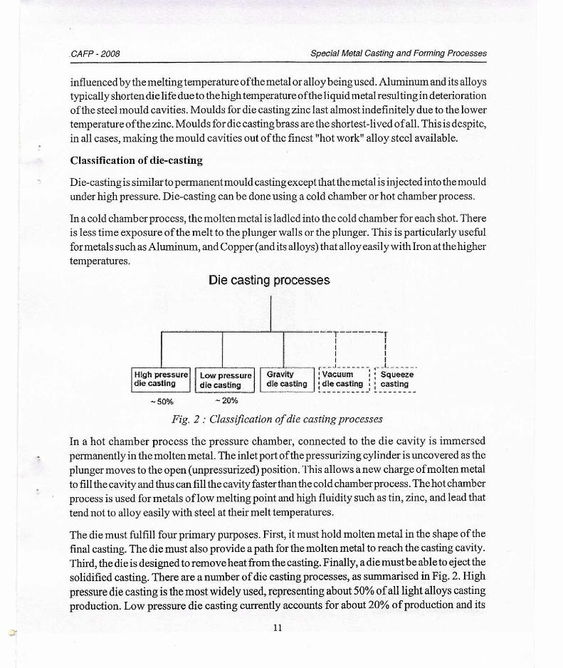
Die-casting is similar to permanent mould casting except that the metal is injected into the mould under high pressure. Die-casting can be done using a cold chamber or hot chamber process.
In a cold chamber process, the molten metal is ladled into the cold chamber for each shot. There is less time exposure of the melt to the plunger walls or the plunger. This is particularly useful for metals such as Aluminum, and Copper (and its alloys) that alloy easily with Iron at the higher temperatures.
Die casting processes
- 50% - 20%
- T I
i 1
i i L
r J i : Vacuum : : Squeeze : die casting : : casting
Fig. 2 : Classification of die casting processes
In a hot chamber process the pressure chamber, connected to the die cavity is immersed permanently in the molten metal. The inlet port of the pressurizing cylinder is uncovered as the plunger moves to the open (unpressurized) position. This allows a new charge of molten metal to fill the cavity and thus can fill the cavity faster than the cold chamber process. The hot chamber process is used for metals of low melting point and high fluidity such as tin, zinc, and lead that tend not to alloy easily with steel at their melt temperatures.
The die must fulfill four primary purposes. First, it must hold molten metal in the shape of the final casting. The die must also provide a path for the molten metal to reach the casting cavity. Third, the die is designed to remove heat from the casting. Finally, a die must be able to eject the solidified casting. There are a number of die casting processes, as summarised in Fig. 2. High pressure die casting is the most widely used, representing about 50% of all light alloys casting production. Low pressure die casting currently accounts for about 20% of production and its
11
Pouring basin Casting
Metal core Filling system
Die location Core Print
CAFP - 2008 Special Metal Casting and Forming Processes
use is increasing. Gravity die casting accounts for the rest, with the exception of a small but growing contribution from the recently introduced vacuum die-casting and squeeze casting process.
Gravity die-casting
A schematic view in Fig. 3 shows the main parts constituting a classical mould for gravity die-casting. Cores (inner parts ofthe mould) are generally made of bonded sand. Gravity die-casting is suitable for mass production and for fully mechanized casting.
Fig. 3 : Schematic view of the main components of a gravity die casting mould
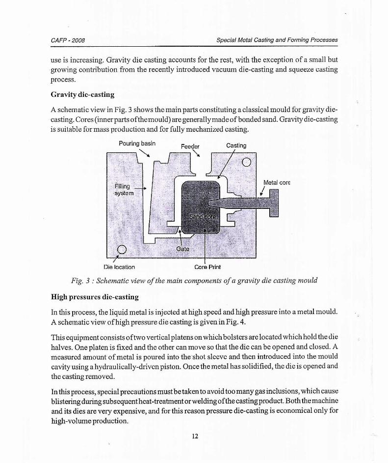
High pressures die-casting
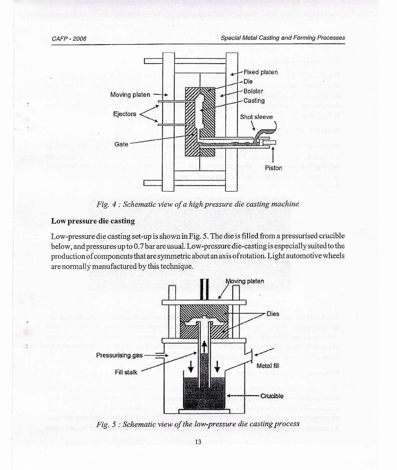
In this process, the liquid metal is injected at high speed and high pressure into a metal mould. A schematic view of high pressure die casting is given in Fig. 4.
This equipment consists of two vertical platens on which bolsters are located which hold the die halves. One platen is fixed and the other can move so that the die can be opened and closed. A measured amount of metal is poured into the shot sleeve and then introduced into the mould cavity using a hydraulically-driven piston. Once the metal has solidified, the die is opened and the casting removed.
In this process, special precautions must betaken to avoid too many gas inclusions, which cause blistering during subsequent heat-treatment or welding of the casting product. Both the machine and its dies are very expensive, and for this reason pressure die-casting is economical only for high-volume production.
12
Moving platen
Ejectors
Gate
Fixed platen
Die
Bolster
Casting
A roo
N.-k-n,,,,,,,viv:55-c,z:,z,-tjiwi•• /
Shot sleeve
Piston
Fig. 4 : Schematic view of a high pressure die casting machine
ving platen
Pressurising gas
Fill stalk
Crucible
CAFP - 2008 Special Metal Casting and Forming Processes
Low pressure die casting
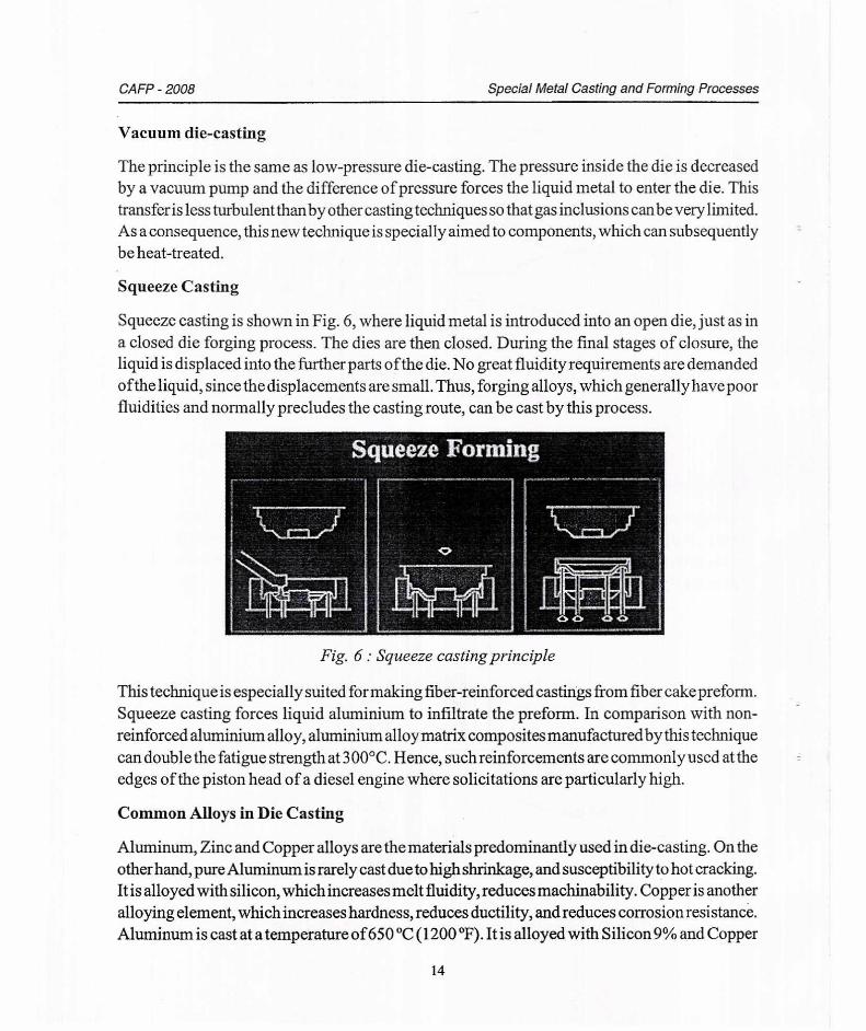
Low-pressure die casting set-up is shown in Fig. 5. The die is filled from a pressurised crucible below, and pressures up to 0.7 bar are usual. Low-pressure die-casting is especially suited to the production of components that are symmetric about an axis ofrotation. Light automotive wheels are normally manufactured by this technique.
Fig. 5 : Schematic view of the low-pressure die casting process
13
CAFP - 2008 Special Metal Casting and Forming Processes
Vacuum die-casting
The principle is the same as low-pressure die-casting. The pressure inside the die is decreased by a vacuum pump and the difference of pressure forces the liquid metal to enter the die. This transfer is less turbulent thanby other casting techniques so that gas inclusions can be very limited. As a consequence, this new technique is specially aimed to components, which can subsequently be heat-treated.
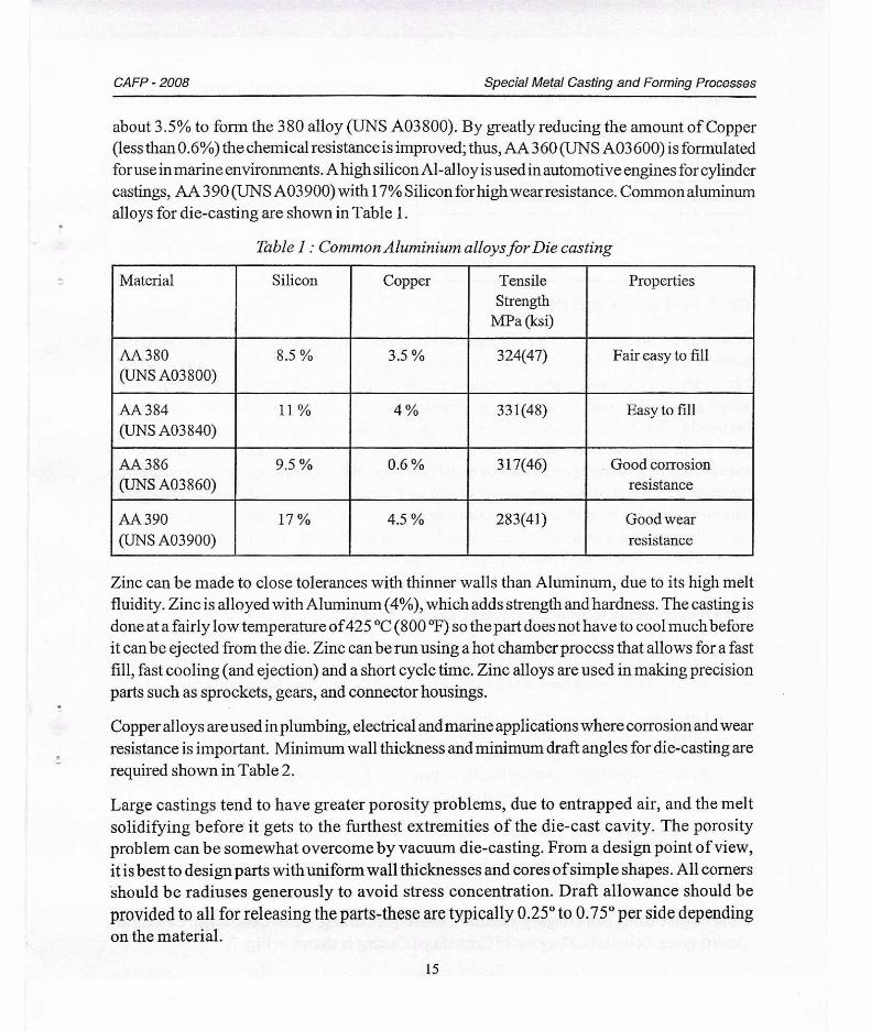
Squeeze Casting
Squeeze casting is shown in Fig. 6, where liquid metal is introduced into an open die, just as in a closed die forging process. The dies are then closed. During the final stages of closure, the liquid is displaced into the further parts of the die. No great fluidity requirements are demanded of the liquid, since the displacements are small. Thus, forging alloys, which generally have poor fluidities and normally precludes the casting route, can be cast by this process.
Fig. 6 : Squeeze casting principle
This technique is especially suited for making fiber-reinforced castings from fiber cake preform. Squeeze casting forces liquid aluminium to infiltrate the preform. In comparison with non-reinforced aluminium alloy, aluminium alloy matrix composites manufactured by this technique can double the fatigue strength at 300°C. Hence, such reinforcements are commonly used at the edges of the piston head of a diesel engine where solicitations are particularly high.
Common Alloys in Die Casting
Aluminum, Zinc and Copper alloys are the materials predominantly used in die-casting. On the other hand, pure Aluminum is rarely cast due to high shrinkage, and susceptibility to hot cracking. It is alloyed with silicon, which increases melt fluidity, reduces machinability. Copper is another alloying element, which increases hardness, reduces ductility, and reduces corrosion resistance. Aluminum is cast at a temperature of 650 °C (1200 °F). It is alloyed with Silicon 9% and Copper
14
CAFP - 2008
Special Metal Casting and Forming Processes
about 3.5% to form the 380 alloy (UNS A03800). By greatly reducing the amount of Copper (less than 0.6%) the chemical resistance is improved; thus, AA 360 (UNS A03 600) is formulated for use in marine environments. A high silicon Al-alloy is used in automotive engines for cylinder castings, AA 390 (UNS A03 900) with 17% Silicon for high wear resistance. Common aluminum alloys for die-casting are shown in Table 1.
Table 1: Common Aluminium alloys for Die casting
Material Silicon Copper Tensile Strength
MPa (ksi)
Properties
AA 380 (UNS A03800)
8.5 % 3.5 % 324(47) Fair easy to fill
AA 384 (UNS A03840)
11 % 4 % 331(48) Easy to fill
AA 386 (UNS A03860)
9.5 % 0.6 % 317(46) Good corrosion resistance
AA 390 (UNS A03900)
17 % 4.5 % 283(41) Good wear resistance
Zinc can be made to close tolerances with thinner walls than Aluminum, due to its high melt fluidity. Zinc is alloyed with Aluminum (4%), which adds strength and hardness. The casting is done at a fairly low temperature of425 °C (800 °F) so the part does not have to cool much before it can be ejected from the die. Zinc can be run using a hot chamber process that allows for a fast fill, fast cooling (and ejection) and a short cycle time. Zinc alloys are used in making precision parts such as sprockets, gears, and connector housings.
Copper alloys are used in plumbing, electrical and marine applications where corrosion and wear resistance is important. Minimum wall thickness and minimum draft angles for die-casting are required shown in Table 2.
Large castings tend to have greater porosity problems, due to entrapped air, and the melt solidifying before it gets to the furthest extremities of the die-cast cavity. The porosity problem can be somewhat overcome by vacuum die-casting. From a design point of view, it is best to design parts with uniform wall thicknesses and cores of simple shapes. All corners should be radiuses generously to avoid stress concentration. Draft allowance should be
provided to all for releasing the parts-these are typically 0.25° to 0.75° per side depending on the material.
15
CAFP - 2008
Special Metal Casting and Forming Processes
Table 2 : Minimum wall thickness and minimum draft angles for die-casting
Material Min. Thicknessmm (in) Min. Draft Angle (0) Material
Aluminum alloys 0.9 mm(0.035 in) 0.5 Aluminum alloys
Zinc alloys 0.6 mm(0.025 in) 0.25 Zinc alloys
Copper alloys (Brass) 1.25 mm(0.050 in) 0.7 Copper alloys (Brass)
CENTRIFUGAL CASTING
Centrifugal casting consists ofproducing castings by causing molten metal to solidify in rotating moulds. The speed of the rotation and metal pouring rate vary with the alloy, size and shape being cast. The following operations include in centrifugal casting, rotation ofmould at a known speed, pouring the molten metal, proper solidification rate, and extraction of the casting from the mould. The idea of employing centrifugal force to make castings had been known for a long time. Centrifugal casting consists of having sand, metal, or ceramic mould that is rotated at high speeds (300 to 3000 rpm) as the molten metal is poured. When the molten metal is poured into the rotating mould, it is thrown against the mould wall, where it remains until it cools and solidifies. The tin bronzes, as for chill casting, are suitable for centrifugal casting and, in addition, the high tensile brasses and aluminum bronzes may be centrifugally cast. This process is, of course, generally used on the larger castings and was originally introduced for the production of gears, worm wheels and cored bars.
CHARACTERISTICS OF CENTRIFUGAL CASTING
- The casting is relatively free from defects
- Non Metallic impurities which segregate toward the bore can be machined off
- Less loss of metal in tundish compared to that in gating and risering in conventional sand casting
- Better mechanical properties tensile, creep, and fatigue strength are increased up to 30% over static and investment casting methods
- Can be employed to manufacture bimetallic pipes
- Centrifugal casting process can be used for fabrication functional gradient metal matrix composite material.
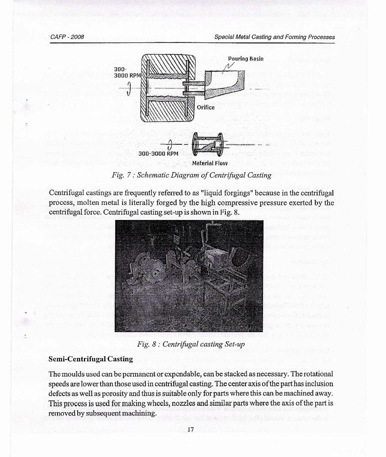
Centrifugal casting as a category includes Centrifugal Casting, Semi-Centrifugal Casting and Centrifuging. Schematic Diagram of Centrifugal Casting is shown in Fig. 7.
16
300- 3000 RPM NM) littHarlit
untilNima
Orifice
Pouring Basin 4/
• CAFP - 2008 Special Metal Casting and Forming Processes
300-3000 RPM
Material Flow Fig. 7 : Schematic Diagram of Centrifugal Casting
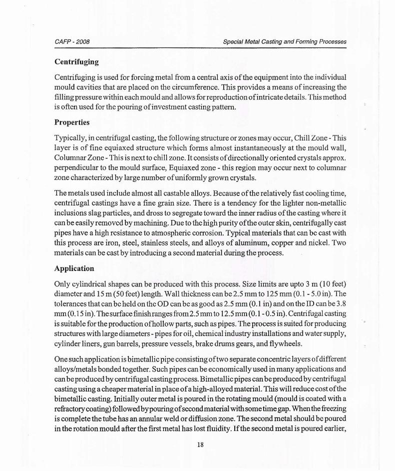
Centrifugal castings are frequently referred to as "liquid forgings" because in the centrifugal process, molten metal is literally forged by the high compressive pressure exerted by the centrifugal force. Centrifugal casting set-up is shown in Fig. 8.
Fig. 8 : Centrifugal casting Set-up
Semi-Centrifugal Casting
The moulds used can be permanent or expendable, can be stacked as necessary. The rotational speeds are lower than those used in centrifugal casting. The center axis of the part has inclusion defects as well as porosity and thus is suitable only for parts where this can be machined away. This process is used for making wheels, nozzles and similar parts where the axis of the part is removed by subsequent machining.
17
CAFP - 2008 Special Metal Casting and Forming Processes
Centrifuging
Centrifuging is used for forcing metal from a central axis of the equipment into the individual mould cavities that are placed on the circumference. This provides a means of increasing the filling pressure within each mould and allows for reproduction of intricate details. This method is often used for the pouring of investment casting pattern.
Properties
Typically, in centrifugal casting, the following structure or zones may occur, Chill Zone - This layer is of fine equiaxed structure which forms almost instantaneously at the mould wall, Columnar Zone - This is next to chill zone. It consists of directionally oriented crystals approx. perpendicular to the mould surface, Equiaxed zone - this region may occur next to columnar zone characterized by large number of uniformly grown crystals.
The metals used include almost all castable alloys. Because of the relatively fast cooling time, centrifugal castings have a fine grain size. There is a tendency for the lighter non-metallic inclusions slag particles, and dross to segregate toward the inner radius of the casting where it can be easily removed by machining. Due to the high purity of the outer skin, centrifugally cast pipes have a high resistance to atmospheric corrosion. Typical materials that can be cast with this process are iron, steel, stainless steels, and alloys of aluminum, copper and nickel. Two materials can be cast by introducing a second material during the process.
Application
Only cylindrical shapes can be produced with this process. Size limits are upto 3 m (10 feet) diameter and 15 m (50 feet) length. Wall thickness can be 2.5 mm to 125 mm (0.1 - 5.0 in). The tolerances that can be held on the OD can be as good as 2.5 mm (0.1 in) and on the ID can be 3.8 mm (0.15 in). The surface finishranges from 2.5 mm to 12.5 mm (0.1- 0.5 in). Centrifugal casting is suitable for the production of hollow parts, such as pipes. The process is suited for producing structures with large diameters - pipes for oil, chemical industry installations and water supply, cylinder liners, gun barrels, pressure vessels, brake drums gears, and flywheels.
One such application is bimetallic pipe consisting of two separate concentric layers of different alloys/metals bonded together. Such pipes can be economically used in many applications and can be produced by centrifugal casting process. Bimetallic pipes can be produced by centrifugal casting using a cheaper material in place of a high-alloyed material. This will reduce cost of the bimetallic casting. Initially outer metal is poured in the rotating mould (mould is coated with a refractory coating) followed bypouring of second material with some time gap. When the freezing is complete the tube has an annular weld or diffusion zone. The second metal should be poured in the rotation mould after the first metal has lost fluidity. If the second metal is poured earlier,
18
CAFP - 2008 Special Metal Casting and Forming Processes
then the composition and thickness of the second metal will be changed. Also if second metal is poured late there won't be good bonding.
Defects in Centrifugal Casting
Conventional static defects like internal shrinkage, gas porosity and nonmetallic inclusions are less likely to occur in centrifugal casting.
Hot tears are developed in centrifugal castings for which the highest rotation speeds are used. Longitudinal tears occur when contraction of casting combined with the expansion ofthe mould, generates hoop stresses exceeding the cohesive strength ofthe metal at temperature in the solidus region.
Segregation- Centrifugal castings are under various forms of segregation thus pushing less dense constituents at centre.
Banding- Sometimes casting produce zones of segregated low melting point constituents such as eutectic phases and sulphide and oxide inclusions. One states vibration is the main cause of banding.
19