near-ir spectrum measurements - arxiv
TRANSCRIPT

Characterisation of Laser Wakefield Acceleration Efficiency with Octave SpanningNear-IR Spectrum Measurements
M.J.V. Streeter,1, 2, 3, ∗ Y. Ma,4, 1, 2 B. Kettle,3 S.J.D. Dann,1, 2 E. Gerstmayr,3 F. Albert,5 N. Bourgeois,6
S. Cipiccia,7 J.M. Cole,3 I.G. Gonzalez,8 A. Higginbotham,9 A.E. Hussein,4, 10 D.A. Jaroszynski,11, 1 K. Falk,12
K. Krushelnick,4 N. Lemos,5 N.C. Lopes,3, 13 C. Lumsdon,9 O. Lundh,8 S.P.D. Mangles,3 Z. Najmudin,3
P.P. Rajeev,6 M. Shahzad,11, 1 M. Smid,12 R. Spesyvtsev,11, 1 D.R. Symes,6 G. Vieux,11, 1 and A.G.R. Thomas4, 1, 2, †
1The Cockcroft Institute, Keckwick Lane, Daresbury, WA4 4AD, United Kingdom2Physics Department, Lancaster University, Lancaster LA1 4YB, United Kingdom
3The John Adams Institute for Accelerator Science,Imperial College London, London, SW7 2AZ, UK
4Center for Ultrafast Optical Science, University of Michigan, Ann Arbor, MI 48109-2099, USA5Lawrence Livermore National Laboratory (LLNL),P.O. Box 808, Livermore, California 94550, USA
6Central Laser Facility, STFC Rutherford Appleton Laboratory, Didcot OX11 0QX, UK7Diamond Light Source, Harwell Science and Innovation Campus, Fermi Avenue, Didcot OX11 0DE, UK
8Department of Physics, Lund University, P.O. Box 118, S-22100, Lund, Sweden9York Plasma Institute, Department of Physics, University of York, York YO10 5DD, UK
10Department of Electrical and Computer Engineering, University of Alberta,9211 116 Street NW Edmonton, Alberta, T6G 1H9, Canada
11SUPA, Department of Physics, University of Strathclyde, Glasgow G4 0NG, UK12ELI-Beamlines, Institute of Physics, Academy of Sciences of the Czech Republic, 18221 Prague, Czech Republic
13GoLP/Instituto de Plasmas e Fusao Nuclear, Instituto Superior Tecnico, U.L., Lisboa 1049-001, Portugal(Dated: November 16, 2020)
We report on high efficiency energy transfer in a GeV-class laser wakefield accelerator. Both thetransfer of energy from the laser to the plasma wakefield, and from the plasma to the acceleratedelectron beam were diagnosed experimentally by simultaneous measurement of the deceleration oflaser photons and the accelerated electrons as a function of acceleration length. The extractionefficiency, which we define as the ratio of the energy gained by the electron beam to the energy lostby the self-guided laser mode, was maximised at 27 ± 2% by tuning of the plasma density, plasmalength and incident laser pulse compression. At higher densities, the laser was observed to fullyredshift over an entire octave, from 800 nm to 1600 nm.
Intense laser pulses can drive compact plasma-basedelectron accelerators using a process known as LaserWakeField Acceleration (LWFA). As the laser pulse prop-agates through a plasma, it drives electron oscillationsthat produce large electrostatic fields, typically of or-der 100 GV/m. LWFA has been successfully used to ac-celerate electrons to > 1 GeV energy levels over inter-action distances on the order of a centimeter [1–6]. Acrucial consideration for LWFAs is the efficiency of en-ergy transfer from the laser to the accelerated particlebunch. In radio-frequency (RF) linear accelerators, ef-ficient operation is achieved by storing the drive energyin a high quality-factor cavity, which is then extractedby multiple electron beams in a bunch train. In high-amplitude plasma-accelerators non-linearities eventuallydamp out the plasma oscillations and so high efficiencyenergy transfer must be achieved within a relatively smallnumber of plasma oscillation periods.
In beam-driven plasma wakefield acceleration(PWFA), the extraction efficiency is simply calcu-lated as the ratio of the energy gained by the witnessbeam, to the energy lost by the driver. Using thismeasure, an efficiency of > 30% has been observedexperimentally [7]. In LWFA, energy transfer to the
plasma wakefield occurs through redshifting of thedriving laser pulse, and so can be determined fromspectral measurement of the post-interaction laser pulse[8, 9]. Combined with measurement of the acceleratedelectron beam spectrum, it is possible to simultaneouslydiagnose the efficiency with which the laser excites theplasma wakefield, and the efficiency with which theelectron beam extracts that energy. Higher-order lasermodes that are not guided in a central filament will notdrive strong plasma waves and therefore do not transfersignificant energy to the wake [10]. Consequently, the‘extraction efficiency’ for LWFA only includes energytransfer from the guided, and therefore redshifted, lasermode. Measuring the electron beam properties andthe input laser energy alone does not provide enoughinformation to infer this quantity.
Regardless of the nature of the driver, 100% extrac-tion efficiency would require that the wake of the wit-ness beam perfectly cancels the plasma wake generatedby the driver. With a suitably chosen trapezoidal elec-tron beam current profile [11], the accelerating field overthe electron bunch can be kept constant at Ez(ξS) whereξS is the location of the head of the electron bunch inthe co-moving frame ξ = z − ct. Doing so allows for si-
arX
iv:2
011.
0137
0v2
[ph
ysic
s.pl
asm
-ph]
13
Nov
202
0

2
multaneous high plasma wake extraction efficiency andlow energy spread for the accelerated beam in linear [11]or non-linear blowout [12–14] regimes. If dephasing oc-curs, then this ideal beam-loading condition can not bemaintained, leading to increased energy spread and loweroverall efficiency. Any modification to the wakefield am-plitude, i.e. as the laser evolves, will affect both the idealbeam-loading condition and the dephasing rate.
In this letter, we present experimental measurementsof the transfer of laser energy into a plasma wakefield andthe efficiency with which that energy was extracted by anelectron beam as it was accelerated to > 1 GeV. This re-quired measurement of the full laser pulse spectrum atthe exit of the plasma, which in this regime extendedup to 1600 nm. Studying the energy transfer betweenthe laser, plasma and electron beam as a function of theplasma length was used to reveal the dynamics responsi-ble for this optimum.
For the driving laser of a LWFA, the energy loss perunit length is given by −dWL/dz = −(WL0/ω0)d〈ω〉/dz,where WL0 and ω0 are the initial laser pulse energy andfrequency, respectively. The electron-beam energy-gainper-unit-length, NBmec
2d〈γ〉/dz, where NB is the num-ber of accelerated electrons and 〈γ〉 =
∫S(γ)dγ/NB is
the average energy of the beam, can be inferred frommeasurements of the electron spectrum S(γ) as a func-tion of plasma length. Therefore, the instantaneous en-ergy extraction efficiency for a LWFA can be written as,
ηb = −NBmec2ω0
WL0
[d〈γ〉dz
] [d〈ω〉dz
]−1. (1)
Due to contributions by dephasing, drive laser evolution,beam injection and beam loss (changing NB), the ex-traction efficiency is not a constant but changes alongthe accelerator length. For the results of this paper, wemeasure the accelerator averaged extraction efficiency ηb,i.e. the ratio of the total energy gained by the electronbeam to the energy lost by the laser pulse.
An experiment was performed (see appendix for theexperimental schematic) with the Gemini laser at theCentral Laser Facility. Each pulse contained 6.3 ± 0.6 Jin a pulse length of τFWHM = 45 ± 4 fs, giving a peakpower of P0 = 134± 22 TW. The linearly polarized pulsewas focused to a spot width of 40(±2)µm ×50(±2)µm(FWHM) with an f/40 parabolic mirror. A deformablemirror was used to optimize the wavefront, giving a peakintensity in vacuum of I0 = 4.6(±0.8)×1018 W cm−2 anda peak normalised vector potential a0 = 1.46 ± 0.12 atfocus.
The laser pulse was focused into a 3D printed two-stage gas cell [15], filled with a 2%/98% nitrogen/heliummix for the first ‘injector’ stage and pure helium in thesecond ‘accelerator’ stage. The cell walls had 1 mm widevertical slits to allow for the gas cell to be translatedvertically. This enabled the accelerator length to be ad-justed continuously as the exit wall was angled at 45 ◦
to the vertical plane. The injector stage has an internallength of 3 mm and the accelerator length was variableover 8-21 mm, giving a total gas cell length 14-26 mm (in-cluding the cell boundaries). The electron density in thegas cells was varied in the range ne = 0−2.6×1018 cm−3,which was diagnosed by observing the spectrum of Ra-man side-scattering from plasma waves generated by lowintensity (a0 < 1), long duration (τFWHM ≈ 200 fs) laserpulses [16].
After interaction with the plasma, the transmittedlaser pulse was reflected from two glass plates into afiber coupler, sampling a 1 cm diameter region. A fibersplitter directed the signal onto two spectrometers, onemeasuring 350–840 nm (Andor Shamrock) and one mea-suring 900–1700 nm (Ocean Optics NIRQuest 512). Therelative spectral sensitivities of the laser spectrometerswas calibrated using a pre-calibrated white light source.The electron beam spectrum was measured using a mag-netic dipole with integrated field strength
∫Bdz =
0.45 Tm, which dispersed electrons in the energy range450–3000 MeV onto a Lanex scintillator.
In order to determine the optimal conditions for elec-tron generation, the gas cell was positioned at its longestlength and the plasma density ne, focus position zf andsecond order spectral phase β(2) of the laser were inde-pendently scanned. The results of a gas cell density scan,for an accelerator length of 21 mm (total plasma length27 mm) and the optimal values of zf and β(2), are plottedin figure 1a-b.
The laser spectrum, shown in figure 1a, was increas-ingly redshifted and broadened at higher plasma density.For the highest plasma density ne = 2.6×1018 cm−3, thelaser spectrum extended to the limit of the spectrometerwith a peak occurring at 1600 nm. Comparatively lit-tle laser energy was blueshifted for the full density rangedemonstrating that ionization blueshift or photon accel-eration at the rear of the plasma wave were not significant[17].
As shown in figure 1b, the highest electron energy oc-curred for ne = 1.5 × 1018 cm−3, where a peak in thespectrum was observed at 1.4 GeV. At higher densities,the maximum electron energies decreased, while the to-tal measured charge remained approximately constant ateNB ≈ 250 pC. The increasing laser redshift indicatesthat a strong plasma wave continued to be driven at thesehigh densities, but the injected electrons experienced lessacceleration.
Figure 1c-d show the result of scanning the acceleratorlength for a fixed density of of ne = 1.25 × 1018 cm−3.The laser (figure 1c redshifted at an approximately lin-ear rate as the acceleration length was increased. Theelectron spectra (figure 1d, shows two distinctive electronbunches were accelerated, with the higher energy compo-nent reaching 1.2 GeV. For plasma length z < 18 mm (ac-celeration cell length z < 13 mm) the charge in the higherenergy component was much reduced, indicating that in-

3
FIG. 1. a) Laser and b) electron spectrum at the exit of the 27 mm gas cell as functions of electron density in the accelerationstage. c) Laser and d) electron beam spectra at the exit of a gas cell as functions of accelerator stage length at ne =1.25 ± 0.06 × 1018 cm−3. The red-bordered region in the laser spectra plots indicates the gap between the measurement rangesof the two spectrometers, which was filled by a Gaussian process regression interpolation model. Each column of each imageshows the average from 3–5 shots at the same conditions. The width of each column is proportional to the bin-width betweenmeasurements.
jection was sensitive to small changes in the plasma pro-file as the cell was translated vertically. Also for thelongest plasma lengths (z > 25 mm), the laser redshiftwas reduced, indicating that less energy was coupled intothe plasma. This was likely due to obstructions to thelaser path at the top of the gas cell slits.
Both the laser and electron beam energies were calcu-lated by integrating the measurements in figure 1 over thespectral axes. For the laser spectrum, there was a smallgap between the ranges of the two spectrometers. In or-der to determine the interacting laser energy, Gaussianprocess regression (GPR) was used to fit the observed sig-nal and interpolate over this region. The relative error ofthe interacting laser energy measurement introduced bythis procedure was calculated from the GPR model un-certainties as less than 3%. Also, as the laser spectrumwas measured on a small sample region of the transmit-ted beam (≈ 1 mrad), we have assumed that the spec-trum is independent of angle. Analysis of transmittedlaser spectra from the PIC simulations (described laterin this paper) indicate that this assumption leads to thelaser depletion being overestimated by ≈ 4%. Finally, itwas assumed that the total photon number of the drivinglaser pulse (Nph = WL0/~ω0) was conserved throughoutthe interaction [8], such that the energy loss can be cal-culated from the change in average laser frequency as inequation (1).
The laser pulse energy loss and electron energy gainare plotted as functions of plasma density in figure 2a.The laser lost more energy for increasing plasma den-sity until reaching a plateau for ne > 1.6 × 1018 cm−3.The electron beam total energy reached a maximum of0.23 ± 0.04 J at ne = 1.6 × 1018 cm−3 and was lower for
both higher and lower plasma densities. The extractionefficiency ηb = −WB/∆WL, plotted in figure 2b, reacheda maximum of 19 ± 2% at ne = 1.05 × 1018 cm−3. In-creasing the plasma density beyond this point resultedin a lower extraction efficiency, even though the electronbeam energy increased.
FIG. 2. a) and c) Electron beam energy (red) and energyloss of the laser (black) and b) and d) extraction efficiency asfunctions of plasma density and length.
The laser energy loss and electron beam energy forthe length scan are shown in figure 2c. The laser en-ergy loss was approximately linearly proportional to theplasma length up to z = 25 mm. The electron beamtotal energy increased suddenly with the appearance ofthe higher energy feature in the electron spectrum (vis-ible in figure 1d), at z = 18 mm. Over the range(20 ≤ z ≤ 26) mm, the electron charge was approxi-
4
mately constant at eNB = 280±90 pC, while the electronbeam total energy increased with z. The extraction ef-ficiency, shown in figure 2d), also increased with lengthfor z < 20 mm as more charge was injected, before sta-bilizing at an average of 23 ± 4% for (20 ≤ z ≤ 26) mmwith a maximum of 27± 2%.
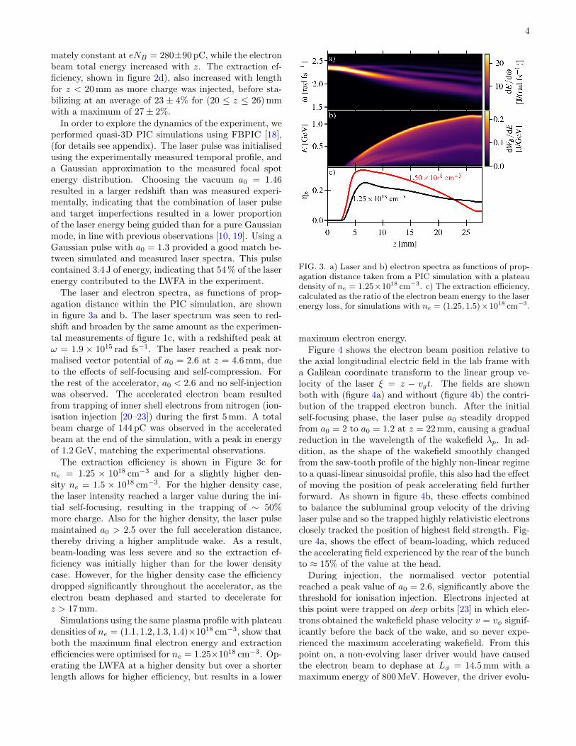
In order to explore the dynamics of the experiment, weperformed quasi-3D PIC simulations using FBPIC [18],(for details see appendix). The laser pulse was initialisedusing the experimentally measured temporal profile, anda Gaussian approximation to the measured focal spotenergy distribution. Choosing the vacuum a0 = 1.46resulted in a larger redshift than was measured experi-mentally, indicating that the combination of laser pulseand target imperfections resulted in a lower proportionof the laser energy being guided than for a pure Gaussianmode, in line with previous observations [10, 19]. Using aGaussian pulse with a0 = 1.3 provided a good match be-tween simulated and measured laser spectra. This pulsecontained 3.4 J of energy, indicating that 54 % of the laserenergy contributed to the LWFA in the experiment.
The laser and electron spectra, as functions of prop-agation distance within the PIC simulation, are shownin figure 3a and b. The laser spectrum was seen to red-shift and broaden by the same amount as the experimen-tal measurements of figure 1c, with a redshifted peak atω = 1.9 × 10¹⁵ rad fs−1. The laser reached a peak nor-malised vector potential of a0 = 2.6 at z = 4.6 mm, dueto the effects of self-focusing and self-compression. Forthe rest of the accelerator, a0 < 2.6 and no self-injectionwas observed. The accelerated electron beam resultedfrom trapping of inner shell electrons from nitrogen (ion-isation injection [20–23]) during the first 5 mm. A totalbeam charge of 144 pC was observed in the acceleratedbeam at the end of the simulation, with a peak in energyof 1.2 GeV, matching the experimental observations.
The extraction efficiency is shown in Figure 3c forne = 1.25 × 1018 cm−3 and for a slightly higher den-sity ne = 1.5 × 1018 cm−3. For the higher density case,the laser intensity reached a larger value during the ini-tial self-focusing, resulting in the trapping of ∼ 50%more charge. Also for the higher density, the laser pulsemaintained a0 > 2.5 over the full acceleration distance,thereby driving a higher amplitude wake. As a result,beam-loading was less severe and so the extraction ef-ficiency was initially higher than for the lower densitycase. However, for the higher density case the efficiencydropped significantly throughout the accelerator, as theelectron beam dephased and started to decelerate forz > 17 mm.
Simulations using the same plasma profile with plateaudensities of ne = (1.1, 1.2, 1.3, 1.4)×1018 cm−3, show thatboth the maximum final electron energy and extractionefficiencies were optimised for ne = 1.25×1018 cm−3. Op-erating the LWFA at a higher density but over a shorterlength allows for higher efficiency, but results in a lower
FIG. 3. a) Laser and b) electron spectra as functions of prop-agation distance taken from a PIC simulation with a plateaudensity of ne = 1.25×1018 cm−3. c) The extraction efficiency,calculated as the ratio of the electron beam energy to the laserenergy loss, for simulations with ne = (1.25, 1.5)×1018 cm−3.
maximum electron energy.Figure 4 shows the electron beam position relative to
the axial longitudinal electric field in the lab frame witha Galilean coordinate transform to the linear group ve-locity of the laser ξ = z − vgt. The fields are shownboth with (figure 4a) and without (figure 4b) the contri-bution of the trapped electron bunch. After the initialself-focusing phase, the laser pulse a0 steadily droppedfrom a0 = 2 to a0 = 1.2 at z = 22 mm, causing a gradualreduction in the wavelength of the wakefield λp. In ad-dition, as the shape of the wakefield smoothly changedfrom the saw-tooth profile of the highly non-linear regimeto a quasi-linear sinusoidal profile, this also had the effectof moving the position of peak accelerating field furtherforward. As shown in figure 4b, these effects combinedto balance the subluminal group velocity of the drivinglaser pulse and so the trapped highly relativistic electronsclosely tracked the position of highest field strength. Fig-ure 4a, shows the effect of beam-loading, which reducedthe accelerating field experienced by the rear of the bunchto ≈ 15% of the value at the head.
During injection, the normalised vector potentialreached a peak value of a0 = 2.6, significantly above thethreshold for ionisation injection. Electrons injected atthis point were trapped on deep orbits [23] in which elec-trons obtained the wakefield phase velocity v = vφ signif-icantly before the back of the wake, and so never expe-rienced the maximum accelerating wakefield. From thispoint on, a non-evolving laser driver would have causedthe electron beam to dephase at Lφ = 14.5 mm with amaximum energy of 800 MeV. However, the driver evolu-

5
FIG. 4. a) Loaded and b) unloaded longitudinal electric fieldand injected electron bunch position (green) over the propa-gation axis z of PIC simulations with ne = 1.25 × 1018 cm−3.The unloaded fields were extracted from a simulation withoutthe ionization injection species. The maximum acceleratingfield position in the first plasma period (black line) is overlaid.
tion acted to mitigate dephasing, resulting in the higherobserved electron beam energy of 1.2 GeV.
Methods for accelerating electrons to energies beyondthe dephasing limit have been explored, including non-uniform plasma profiles [24–27] or by using alternativelaser focusing geometries with spatio-temporal couplings[28–30]. Phase-locked LWFA dynamics in a constant den-sity plasma have been observed in PIC simulations pre-viously [31] although in that case it was attributed topulse depletion. As depletion increases the wakefield am-plitude due to laser redshifting (a0 ∝ ω−1/2), this effectalone would actually increase the wakefield wavelengthof and cause the electron beam to dephase more rapidly.Here we show that through careful management of thelaser evolution it is possible to mitigate dephasing, sothat pulse depletion determines the electron energy limitfor the accelerator.
In conclusion, we have measured the extraction ef-ficiency for an LWFA, which reached a maximum of27 ± 2%, close to that previously observed in electron-beam-driven PWFA [7]. The measurements indicatedthat only approximately 20% of the laser pulse energywas transferred to the plasma wakefield, with approx-imately half of the laser energy wasted due to a non-ideal focal spot. The overall efficiency could thereforebe increased by improving the spatial distribution of thelaser pulse, as indicated by PIC simulations with a Gaus-sian distribution as well as previous studies on the effectsof non-Gaussian focal spots [10]. Laser energy that re-mains after the interaction could possibly be recoveredto further improve the total efficiency of a LWFA facility.For the highest plasma densities and longest interactionlength, the laser pulse spectrum was observed to spana complete octave from 800–1600 nm. Further harness-
ing of these effects may open up a route to relativisticintensity single cycled mid-IR laser pulses [32–34].
We acknowledge support from the UK STFCcore grants ST/P002056/1 (Cockcroft Institute),ST/P000835/1 (John Adams Institute), the NationalScience Foundation (Grant No. 1804463) and the AirForce Office of Scientific Research (Grant No. FA9550-16-1-0121). F.A. acknowledges funding from the DOEEarly Career research program (Fusion Energy SciencesSCW1575-1).
∗ [email protected]† [email protected]
[1] W. P. Leemans, B. Nagler, A. J. Gonsalves, C. Toth,K. Nakamura, C. G. R. Geddes, E. Esarey, C. B.Schroeder, and S. M. Hooker, Nature Physics 2, 696(2006).
[2] S. Kneip, S. R. Nagel, S. F. Martins, S. P. D. Man-gles, C. Bellei, O. Chekhlov, R. J. Clarke, N. Delerue,E. J. Divall, G. Doucas, K. Ertel, F. Fiuza, R. Fonseca,P. Foster, S. J. Hawkes, C. J. Hooker, K. Krushelnick,W. B. Mori, C. A. J. Palmer, K. Ta Phuoc, P. P. Rajeev,J. Schreiber, M. J. V. Streeter, D. Urner, J. Vieira, L. O.Silva, and Z. Najmudin, Physical Review Letters 103,035002 (2009).
[3] C. E. Clayton, J. E. Ralph, F. Albert, R. A. Fonseca,S. H. Glenzer, C. Joshi, W. Lu, K. A. Marsh, S. F. Mar-tins, W. B. Mori, A. Pak, F. S. Tsung, B. B. Pollock,J. S. Ross, L. O. Silva, and D. H. Froula, Physical Re-view Letters 105, 105003 (2010).
[4] X. Wang, R. Zgadzaj, N. Fazel, Z. Li, S. A. Yi, X. Zhang,W. Henderson, Y.-Y. Chang, R. Korzekwa, H.-E. Tsai,C.-H. Pai, H. Quevedo, G. Dyer, E. Gaul, M. Martinez,A. C. Bernstein, T. Borger, M. Spinks, M. Donovan,V. Khudik, G. Shvets, T. Ditmire, and M. C. Downer,Nature Communications 4, 1988 (2013).
[5] W. P. Leemans, A. J. Gonsalves, H.-S. Mao, K. Naka-mura, C. Benedetti, C. B. Schroeder, C. Toth, J. Daniels,D. E. Mittelberger, S. S. Bulanov, J.-L. Vay, C. G. R.Geddes, and E. Esarey, Physical Review Letters 113,245002 (2014).
[6] A. J. Gonsalves, K. Nakamura, J. Daniels, C. Benedetti,C. Pieronek, T. C. H. de Raadt, S. Steinke, J. H.Bin, S. S. Bulanov, J. van Tilborg, C. G. R. Ged-des, C. B. Schroeder, C. Toth, E. Esarey, K. Swanson,L. Fan-Chiang, G. Bagdasarov, N. Bobrova, V. Gasilov,G. Korn, P. Sasorov, and W. P. Leemans, Physical Re-view Letters 122, 084801 (2019).
[7] M. Litos, E. Adli, W. An, C. I. Clarke, C. E. Clayton,S. Corde, J. P. Delahaye, R. J. England, A. S. Fisher,J. Frederico, S. Gessner, S. Z. Green, M. J. Hogan,C. Joshi, W. Lu, K. A. Marsh, W. B. Mori, P. Mug-gli, N. Vafaei-Najafabadi, D. Walz, G. White, Z. Wu,V. Yakimenko, and G. Yocky, Nature 515, 92 (2014).
[8] E. Esarey, C. B. Schroeder, and W. P. Leemans, Reviewsof Modern Physics 81, 1229 (2009).
[9] S. Shiraishi, C. Benedetti, A. J. Gonsalves, K. Nakamura,B. H. Shaw, T. Sokollik, J. van Tilborg, C. G. R. Geddes,C. B. Schroeder, C. Toth, E. Esarey, and W. P. Leemans,

6
Physics of Plasmas 20, 063103 (2013).[10] J. Vieira, S. F. Martins, F. Fiuza, C. K. Huang, W. B.
Mori, S. P. Mangles, S. Kneip, S. Nagel, Z. Najmudin,and L. O. Silva, Plasma Physics and Controlled Fusion54, 055010 (2012).
[11] T. Katsouleas, S. Wilks, P. Chen, J. M. Dawson, andJ. Su, Particle Accelerators 22, 81 (1987).
[12] S. Gordienko and A. Pukhov, Physics of Plasmas 12,043109 (2005).
[13] W. Lu, M. Tzoufras, C. Joshi, F. Tsung, W. Mori,J. Vieira, R. Fonseca, and L. Silva, Physical Review Spe-cial Topics - Accelerators and Beams 10, 061301 (2007).
[14] M. Tzoufras, W. Lu, F. S. Tsung, C. Huang, W. B. Mori,T. Katsouleas, J. Vieira, R. A. Fonseca, and L. O. Silva,Physical Review Letters 101, 145002 (2008).
[15] A. E. Hussein, N. Senabulya, Y. Ma, M. J. V. Streeter,B. Kettle, S. J. D. Dann, F. Albert, N. Bourgeois,S. Cipiccia, J. M. Cole, O. Finlay, E. Gerstmayr, I. G.Gonzalez, A. Higginbotham, D. A. Jaroszynski, K. Falk,K. Krushelnick, N. Lemos, N. C. Lopes, C. Lumsdon,O. Lundh, S. P. D. Mangles, Z. Najmudin, P. P. Rajeev,C. M. Schleputz, M. Shahzad, M. Smid, R. Spesyvtsev,D. R. Symes, G. Vieux, L. Willingale, J. C. Wood, A. J.Shahani, and A. G. R. Thomas, Scientific Reports 9,3249 (2019).
[16] T. Matsuoka, C. McGuffey, P. G. Cummings,Y. Horovitz, F. Dollar, V. Chvykov, G. Kalintchenko,P. Rousseau, V. Yanovsky, S. S. Bulanov, A. G. R.Thomas, A. Maksimchuk, and K. Krushelnick, PhysicalReview Letters 105, 034801 (2010).
[17] J. Schreiber, C. Bellei, S. P. D. Mangles, C. Kamperidis,S. Kneip, S. R. Nagel, C. A. J. Palmer, P. P. Rajeev,M. J. V. Streeter, and Z. Najmudin, Physical ReviewLetters 105, 235003 (2010).
[18] R. Lehe, M. Kirchen, I. A. Andriyash, B. B. Godfrey,and J.-L. Vay, Computer Physics Communications 203,66 (2016).
[19] S. P. D. Mangles, G. Genoud, M. S. Bloom, M. Burza,Z. Najmudin, A. Persson, K. Svensson, A. G. R. Thomas,and C.-G. Wahlstrom, Physical Review Special Topics -Accelerators and Beams 15, 011302 (2012).
[20] T. P. Rowlands-Rees, C. Kamperidis, S. Kneip, A. J.Gonsalves, S. P. D. Mangles, J. G. Gallacher, E. Brunetti,T. Ibbotson, C. D. Murphy, P. S. Foster, M. J. V.Streeter, F. Budde, P. A. Norreys, D. A. Jaroszynski,K. Krushelnick, Z. Najmudin, and S. M. Hooker, Phys-ical Review Letters 100, 105005 (2008).
[21] A. Pak, K. A. Marsh, S. F. Martins, W. Lu, W. B.Mori, and C. Joshi, Physical Review Letters 104, 025003(2010).
[22] C. McGuffey, A. G. R. Thomas, W. Schumaker, T. Mat-suoka, V. Chvykov, F. J. Dollar, G. Kalintchenko,V. Yanovsky, A. Maksimchuk, K. Krushelnick, V. Y. By-chenkov, I. V. Glazyrin, and a. V. Karpeev, PhysicalReview Letters 104, 025004 (2010).
[23] M. Chen, E. Esarey, C. B. Schroeder, C. G. R. Ged-des, and W. P. Leemans, Physics of Plasmas 19, 033101(2012).
[24] A. Pukhov and I. Kostyukov, Physical Review E 77,025401(R) (2008).
[25] E. Guillaume, A. Dopp, C. Thaury, K. Ta Phuoc, A. Lif-schitz, G. Grittani, J. P. Goddet, A. Tafzi, S. W. Chou,L. Veisz, and V. Malka, Physical Review Letters 115,155002 (2015).
[26] Y. Ma, D. Seipt, S. J. Dann, M. J. Streeter, C. A. Palmer,L. Willingale, and A. G. Thomas, Physics of Plasmas 25,113105 (2018).
[27] J. D. Sadler, C. Arran, H. Li, and K. A. Flippo, PhysicalReview Accelerators and Beams 23, 021303 (2020).
[28] A. Debus, R. Pausch, A. Huebl, K. Steiniger, R. Widera,T. E. Cowan, U. Schramm, and M. Bussmann, PhysicalReview X 9, 031044 (2019).
[29] J. P. Palastro, J. L. Shaw, P. Franke, D. Ramsey, T. T.Simpson, and D. H. Froula, Physical Review Letters 124,134802 (2020).
[30] C. Caizergues, S. Smartsev, V. Malka, and C. Thaury,Nature Photonics 14, 475 (2020).
[31] W. Li, J. Liu, W. Wang, Z. Zhang, Q. Chen, Y. Tian,R. Qi, C. Yu, C. Wang, T. Tajima, R. Li, and Z. Xu,Applied Physics Letters 104, 093510 (2014).
[32] M. J. V. Streeter, S. Kneip, M. S. Bloom, R. A. Bendoyro,O. Chekhlov, A. E. Dangor, A. Dopp, C. J. Hooker,J. Holloway, J. Jiang, N. C. Lopes, H. Nakamura, P. A.Norreys, C. A. J. Palmer, P. P. Rajeev, J. Schreiber,D. R. Symes, M. Wing, S. P. D. Mangles, and Z. Naj-mudin, Physical Review Letters 120, 254801 (2018).
[33] Z. Nie, C.-H. Pai, J. Hua, C. Zhang, Y. Wu, Y. Wan,F. Li, J. Zhang, Z. Cheng, Q. Su, S. Liu, Y. Ma, X. Ning,Y. He, W. Lu, H.-H. Chu, J. Wang, W. B. Mori, andC. Joshi, Nature Photonics 12, 489 (2018).
[34] Z. Nie, C.-H. Pai, J. Zhang, X. Ning, J. Hua, Y. He,Y. Wu, Q. Su, S. Liu, Y. Ma, Z. Cheng, W. Lu, H.-H.Chu, J. Wang, C. Zhang, W. B. Mori, and C. Joshi,Nature Communications 11, 2787 (2020).
APPENDIX
Experimental Setup
VIS Spectrometer
NIR Spectrometer
Electron spectrometerHeHe + N
Laser
Gas cell
BLength adjustment
FIG. 5. Experimental schematic showing the gas cell geome-try, the electron spectrometer and the NIR (900–1700 nm) andVIS (350–840 nm) spectrometers which measured the trans-mitted laser pulse.
Simulations
Simulations were performed using the quasi-3DParticle-In-Cell (PIC) code FBPIC (https://fbpic.github.io/index.html) using cylindrical symmetrywith azimuthal mode decomposition. The simulation do-main was 100× 80µm in the propagation (z) and radial

7
r axes, which were divided into 2000× 100 cells with twoazimuthal modes. The plasma electrons were representedby 2× 2× 8 macro-particles per cell in the z, r and θ di-rections. The plasma was initialized with a density of1.25 × 1018 mm−3, with 500µm linear ramps either side
of a 26 mm plateau. The temporal profile of the laserpulse was taken from FROG measurements of the inputlaser pulses during the experiment. Measurements of thelaser focal spot were used to fit a 2D Gaussian transverseprofile as a(x, y, t) = a(t) exp
[−(x/σx)2 − (y/σy)2
]with
σx = 40µm and σy = 32µm.