ncta13-examining the future access network
DESCRIPTION
DSASDTRANSCRIPT
Managing Cable TV Migration to IP – Part 1
Series Introduction: Market Drivers and Tech Challenges
Examining the Future Evolution of the Access Network
Tom Cloonan, CTO Network Solutions, ARRIS
Michael Emmendorfer, Sr. Director Solutions Architecture, ARRIS

© ARRIS 2013. All rights reserved. September 16, 2013
Contents
Executive Summary ......................................................................................................................... 1
Introduction ...................................................................................................................................... 4
Question #1: Are Cable Networks Limited by the RF Video and Data Technologies? ................... 4
Question #2: Are Cable Networks Limited by the FTTN Optical Technology? ............................. 17
Question #3: What Stays In The Head-end And What Moves To The Node? .............................. 28
Conclusion ..................................................................................................................................... 33
Acknowledgements ....................................................................................................................... 34
References .................................................................................................................................... 34

1 © ARRIS 2013. All rights reserved.
Executive Summary
Question #1: Are cable networks “limited by” the RF video and data technologies which are based on ITU-T J.83 annex A/B/C for downstream & CableLabs DOCSIS 2.0 Upstream?
The capability of the cable access network to increase b/s/Hz is “limited by” the Radio Frequency (RF) Video and Data Technologies available today. These are based on Physical (PHY) Layer technologies defined by the ITU-T J.83 for the downstream used for digital video and DOCSIS downstream and CableLabs DOCSIS 2.0 is also limiting capacity in b/s/Hz.
Confirmation of Problem #1
In the downstream, the real-world cable performance measurements of 20 million cable modems proved that the current RF Data Technologies based on DOCSIS / ITU-T J.83 is the limiting factor to maximize b/s/Hz. There is nothing that MSOs could do to increase b/s/Hz for any customer, because the current J.83 technology for video and data services can operate no higher than 256 QAM.
In the upstream, the ARRIS Interactive System Performance model considered the spectrum bands of Sub-split (5-42 MHz), Mid-split (5-85 MHz), and High-split (5-200 MHz); this proved that the current DOCSIS upstream technology (using A-TDMA 64 QAM) is the limiting factor to achieving more b/s/Hz. The model showed that if a new RF Data Technology were available which defined higher modulation orders (up to 4096 QAM) upstream, and used a better FEC, that the plant SNR of the channel could support higher order modulations (estimated at 2048 QAM for Sub-split, 1024 QAM for Mid-split QAM, and 512 QAM for High- split).
Solution to Problem #1
DOCSIS 3.1 to the rescue! The use of DOCSIS 3.1 may define four core features that will allow the MSO to maximize the network b/s/Hz; these features may include:
(1) Higher Order Modulation
(2) Modern FEC
(3) Multiple Modulation Profiles

2 © ARRIS 2013. All rights reserved.
(4) Backward Compatibility
Question #2: Are Cable Networks “limited” by the FTTN Optical Technology which is based primarily on Amplitude Modulation optical technology to/from the node?
In the future the capability of the cable access network to increase b/s/Hz will be “limited” by the fiber to the node (FTTN) optical technology. The only technology used for forward transmission, and one which also makes up the majority of the return transmission, both use an optical technology called Amplitude Modulation (AM).
Confirmation of Problem #2
The ARRIS upstream model confirmed that the current RF Data technology using DOCSIS A-TDMA with a maximum of 64 QAM is limiting MSOs from increasing b/s/Hz on the upstream. This model was used to confirm problem # 2. The model assumed the use of AM Optics, using Un-cooled DFB for use up to 40 km and assumed a single wavelength. Then the model assumed the use of DOCSIS 3.1 with all of the new PHY layer improvements, such as OFDMA, a pair of error correction technology (LDPC inner code, BCH outer code), and the expansion in the available Modulation order up to 4096 QAM. The model estimated Sub-split DOCSIS 3.1 modulation at 2048 QAM, Mid-split at 1024 QAM, and High-split at 512 QAM.
Then a single feature was changed in the model; we replaced the Amplitude Modulation optical technology with a Digital Optics technology using Broadband Digital Return. This single change enables all spectrum splits options including, Sub-split, Mid-split and High-split to be capable of reaching 4096 QAM in the upstream.
Though the model suggests the use of very high order modulation, it is important to know this does not account for noise conditions related to external interference or burst noise events. The model suggests the CNR of the channel will support very high order modulation; however these modulation formats will need to be supported from the cable modem to the burst receiver in the head-end. It is too early to tell if the upstream will support as high a modulation order as the model suggests, as these systems are not available at this time.
Solution to Problem #2
The use of Amplitude Modulation optics can support high-order modulation for the Sub-split and Mid-split bands. The use of digital optics like Broadband Digital Return may enable the use of the full DOCSIS 3.1 modulation format upstream to include 4096 QAM. The High-split spectrum choice had the most modulation complexity gain with

3 © ARRIS 2013. All rights reserved.
the use of digital optics. The downstream was not modeled for use of digital optics, however based on the cable modem downstream cable modem measurements, using Amplitude Modulation Forward may support high order modulation formats (like those planned for DOCSIS 3.1).
Question #3 Moving from AM Optics to Digital Optics for FTTN will force us to place PHY or MAC/PHY Access Layer Functions in the Node. What stays in the Head-end; and what moves to the node?
Moving to Digital Optical Technology for FTTN will change the access layer architecture, placing PHY or MAC/PHY functions in the node. A) We need to determine what functions remain in the head-end and those to be placed in the node. B) We need to determine the network access layer architecture if portions of the PHY or MAC/PHY are separated between the head-end and the node, as this will impact the system architecture for CCAP and the connections and functions it contains in this new Digital Fiber Coax world. The paper provides an overview of the functions that may reside in the head-end and node location depending on the Remote Access Architecture selection.

4 © ARRIS 2013. All rights reserved.
Introduction
The capacity of the cable access network depends on several factors. These factors may include network operations, network architecture, spectrum selection, spectrum allocation, spectral load, RF technology, and optical technology. We are finding that overall MSO operations and design practices will not be the limiting factor to maximize capacity. This paper suggests that today’s cable network capacity or b/s/Hz is limited by the Radio Frequency (RF) Technologies supporting Digital Video and Data Services. This paper also suggest that as improvements are made to the RF Data Technology, such as DOCSIS 3.1, that the next limiting factor will be the Optical Technology to/from the HFC node. As our industry expands spectrum in the downstream and upstream, the current optical technology will increasingly become a limiting factor to maximize b/s/Hz. Additionally, as MSOs have a desire to reduce facilities and expand the optical distance between head-end and fiber node this will also limit the system b/s/Hz, based on today’s optical technology, Amplitude Modulation.
This paper will focus on the three core areas of the cable access network that are increasingly becoming an integral part for maximizing spectral capacity. The sections that follow will be organized by the identified questions as stated above. In those sections we will provide additional detail to the scope of the problems and suggest solutions.
Question #1: Are Cable Networks Limited by the RF Video and Data Technologies?
In order to determine the limiting factors of today’s cable network an assessment of the RF technology attributes must be measured against the performance measurements of the cable network.
Overview of the Current RF Video and Data Technologies
The digital video and DOCSIS services deployed by cable operators around the world use an RF technology defined in Recommendation ITU-T J.83 and the four Annexes (Annexes A, B, C, and D). This standard defined the physical (PHY) layer technology used for digital video MPEG-TS and DOCSIS downstream specifications through version 3.0.
The main differences in the ITU-T J.83 annexes will be the channel coding and modulation specified, as well as the channel width. The highest order modulation in all versions is 256 QAM. A key attribute of the annexes is the selection of error correction

5 © ARRIS 2013. All rights reserved.
technology. Annex A/C/D defines a single error correction technology called Reed-Solomon. The ITU-T J.83 Annex B uses outer FEC called Reed-Solomon (R-S) and an inner FEC called Trellis Coded Modulation (TCM). The use of trellis coding in J.83 annex B is embedded in the modulation process. The use of an inner and outer FEC means that J.83 annex B is more robust than the annex A/C/D versions. The impact of these differences in FEC means that J.83 Annex A/C will require about 2 dB better system performance than J.83 Annex B to support the same modulation format and assuming about the same code rate for each [2]. The applications that use J.83 annexes and the SNR (dB) requirements are found in tables 1 and 2 respectively.
J.83 Error Correction Technology [1]:
ITU-T J.83 Annex A/C uses Reed-Solomon Downstream
ITU-T J.83 Annex B uses Trellis Code Modulation (TCM) inner FEC and Reed Solomon (outer FEC)
ITU-T J.83-A Euro-DOCSIS Annex A DVB-C
ITU-T J.83-B DOCSIS Annex B Japanese DOCSIS Annex C ATSC/SCTE
ITU-T J.83-C Japanese Digital Video Table 1: ITU-T J.83 Applications
J.83 Annex Coded SNR Assuming AWGN
Minimum Operating SNR Recommendation
J.83-A 29 dB 32 dB J.83-B 27 dB 30 dB J.83-C 29 dB 32 dB Assumptions: The coded value assumes a ~ 90% code rate
Table 2: SNR (dB) for 256 QAM
The upstream RF data technologies are based on CableLabs DOCSIS 2.0 standard called Advanced Time Division Multiplex Access (A-TDMA) and Synchronous Code Division Multiple Access (S-CDMA). These have different modulation and error correction technologies defined below:
Method Error Correction Technology A-TDMA Reed-Solomon (R-S) 64 QAM
6 © ARRIS 2013. All rights reserved.
S-CDMA Trellis Code Modulation (TCM) & Reed-Solomon (R-S) 128 QAM Table 3: Upstream DOCSIS Error Correction Technologies
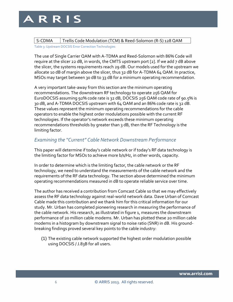
The use of Single Carrier QAM with A-TDMA and Reed-Solomon with 86% Code will require at the slicer 22 dB, in words, the CMTS upstream port [2]. If we add 7 dB above the slicer, the systems requirements reach 29 dB. Our models used for the upstream we allocate 10 dB of margin above the slicer, thus 32 dB for A-TDMA 64 QAM. In practice, MSOs may target between 30 dB to 33 dB for a minimum operating recommendation.
A very important take-away from this section are the minimum operating recommendations. The downstream RF technology to operate 256 QAM for EuroDOCSIS assuming 92% code rate is 32 dB, DOCSIS 256 QAM code rate of 90.5% is 30 dB, and A-TDMA DOCSIS upstream with 64 QAM and an 86% code rate is 32 dB. These values represent the minimum operating recommendations for the cable operators to enable the highest order modulations possible with the current RF technologies. If the operator’s network exceeds these minimum operating recommendations thresholds by greater than 3 dB, then the RF Technology is the limiting factor.
Examining the “Current” Cable Network Downstream Performance
This paper will determine if today’s cable network or if today’s RF data technology is the limiting factor for MSOs to achieve more b/s/Hz, in other words, capacity.
In order to determine which is the limiting factor, the cable network or the RF technology, we need to understand the measurements of the cable network and the requirements of the RF data technology. The section above determined the minimum operating recommendations measured in dB to operate reliable service over time.
The author has received a contribution from Comcast Cable so that we may effectively assess the RF data technology against real-world network data. Dave Urban of Comcast Cable made this contribution and we thank him for this critical information for our study. Mr. Urban has completed pioneering research in measuring the performance of the cable network. His research, as illustrated in figure 1, measures the downstream performance of 20 million cable modems. Mr. Urban has plotted these 20 million cable modems in a histogram by downstream signal to noise ratio (SNR) in dB. His ground-breaking findings proved several key points to the cable industry:
(1) The existing cable network supported the highest order modulation possible using DOCSIS / J.83B for all users.

7 © ARRIS 2013. All rights reserved.
(2) Though the distribution of cable modem performance is vastly different, nearly all devices could support higher order modulation formats or more b/s/Hz if available.
(3) This work is credited with convincing the industry to support in the future the use of Multiple Modulation Profiles (MMP). The use of MMP gives groups of modems sharing common SNR the ability to use the highest order modulation possible, maximizing b/s/Hz.
Figure 1: 20 Million Cable Modem Downstream Histogram
The cable modem (CM) measurements and other tools as well as test points, will paint the entire picture for the operators to verify the use of higher order modulations. The CM histogram is a collection point; and others are needed as well, like EOL (end-of-line) measurements.
Estimating the Cable Network Upstream Performance
To estimate the use of the upstream cable plant and future spectrum splits, ARRIS built a return path model. The ARRIS Upstream HFC Performance Model is an assessment of the Noise and Attenuation in the Optical and Coaxial Segments. The model considers many spectrum splits from 5-42, 5-85, 5-238, and 5-500 MHz, and several Top-split spectrum options. The model proved that Top-split, placing the upstream above 900 MHz or much higher, was too costly and consideration for Top-split was abandoned by the industry in late 2011. The ARRIS model has been vetted by MSOs, fellow suppliers, and was contributed to CableLabs.

8 © ARRIS 2013. All rights reserved.
The main purpose of the ARRIS Upstream HFC Performance Model is an analysis of the HFC Optical and Coaxial segment of the network under “normal operating conditions.” In a given spectrum split the model estimates the system carrier to noise (C/N) to determine the highest upstream modulation type that may be used. The estimated C/N is then matched using OFDMA with LDPC and BCH error correction technology, recommended for DOCSIS 3.1, and the highest modulation format, given the assumptions used in the model. The figure below illustrates the areas of study in the model.
Figure 2: Major Considerations for Coaxial Network Performance
The key output of the model is the estimated system C/N and the modulation type as seen in the highlighted red boxes in Table 4. The model shows that the upstream could support higher order modulation to increase the b/s/Hz and overall system capacity if DOCSIS 2.0 had defined support. The model estimates the modulation type possible, assuming DOCSIS 3.1 technology.

9 © ARRIS 2013. All rights reserved.
Table 4: DOCSIS 3.1 Capacity Prediction with Several Upstream Splits and AM Optical Technology
Though the model suggests the use of very high order modulation, it is important to know this does not account for noise conditions related to external interference or burst noise events. The model suggests the C/N of the channel will support very high order modulation, however these modulation formats will need to be supported from the cable modem to the burst receiver in the head-end. It is too early to tell if the upstream will support as high a modulation order as the model suggests, as these systems are not available at this time.
Background on the ARRIS Upstream Model
It is important to understand what the model is and what it is not. In summary, the model considers the components, which comprise the access layer for the upstream. This includes the optical technology, distance between head-end and node, coaxial electronics, passives, coaxial cable types and lengths, modem power, and many other factors. The diagram in figure 2 and table 4, illustrates the measured parameters in the ARRIS Model.
The model:
Calculates the performance of the Optical and Coaxial segment
Has flexibility to account for different network architectures and components
Accounts for distance variations in the optical and coaxial segments

10 © ARRIS 2013. All rights reserved.
Accounts for various service group sizes to adjust for noise funneling effects
Accounts for noise contribution of the HFC Network
Accounts for Attenuation
Accounts for temperature variation in many areas
Estimates DOCSIS 3.1 Capacity
Model defines Operator Margin of 10 dB above the slicer for a “coded” LDPC and BCH modulation format as defined in Figure 7 called “DOCSIS 3.0 versus DOCSIS 3.1 Modulation C/N” at the end of this section.
The model does not account for:
Noise conditions related to external interference or burst noise events
Faulty components
Variables in Combining
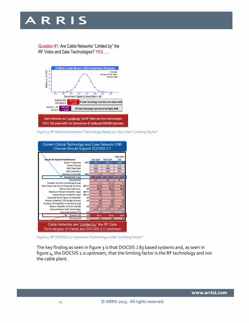
Answer #1: Cable Networks ARE Limited by the RF Video and Data Technologies
The downstream and upstream capacity is limited by the current RF video and data
technologies, based on ITU-T J.83 and DOCSIS 2.0. In figure 3, the current DOCSIS
based systems using J.83 Annex B shows the highest order modulation of 256 QAM
provides complete coverage for all users because the network supports greater than 30
dB. The use of EuroDOCSIS J.83 Annex A in this example provides near full coverage.
11 © ARRIS 2013. All rights reserved.
Figure 3: RF Data Downstream Technology based on J.83 is the “Limiting Factor”
Figure 4: RF DOCSIS 2.0 Upstream Technology is the “Limiting Factor”
The key finding as seen in figure 3 is that DOCSIS J.83 based systems and, as seen in figure 4, the DOCSIS 2.0 upstream, that the limiting factor is the RF technology and not the cable plant.

12 © ARRIS 2013. All rights reserved.
Question #1 Solution: Modernize RF Data Technology with A New PHY Layer: DOCSIS 3.1
Question #1 Solution Summary
This paper proves that the cable access network is now limited by ITU-T J.83 technology for the downstream and the DOCSIS 2.0 technology for the upstream. These technologies were defined as much as 15 years ago and by today’s standard have low order modulation formats and an old FEC.
DOCSIS 3.1 to the rescue! The future use of DOCSIS 3.1 has four core features that will allow the MSO to maximize the network capacity or b/s/Hz. Possible DOCSIS 3.1 key features:
Figure 5: Possible DOCSIS 3.1 Tool Box to Maximize Capacity b/s/Hz
As illustrated in the downstream figure 3 and the upstream analysis as shown in figure 4, that CNR of the channel could support higher modulation if available.

13 © ARRIS 2013. All rights reserved.
Figure 6: DOCSIS 3.1 Enables the MSOs to Maximize Spectrum Increasing b/s/Hz
The above figure 6, illustrates the point that the current RF data technology was the limiting factor preventing MSOs from increasing downstream network capacity in b/s/Hz. This also suggests the use of higher orders of modulation to obtain more capacity (that is possible with DOCSIS 3.1 over the “existing” Optical and Coaxial network). However, not all users can use the same order modulations and the introduction of the use of multiple modulation profiles (MMP) is important. The use of MMP will allow groups of users the ability to reach the highest order possible, so that the network as a whole may be optimized and to maximize capacity and b/s/Hz. The use of backward compatibility allows spectrum to be shared between legacy cable modems and new modems, which support both legacy and new DOCSIS technology, avoiding a spectrum tax.
The existing cable network downstream and upstream performance can support higher order modulation formats than those available today. The support of higher order modulations with the existing network may not be ubiquitous across the MSO footprint or even within a serving group as some segments of the network will differ in performance.

14 © ARRIS 2013. All rights reserved.
Question #1 Solution Details
This section will provide details on the recommendation ARRIS made to the industry beginning in February of 2011 through February 2012, which defined the core features of what later became DOCSIS 3.1. In May 2012, technology leaders from Cisco, ARRIS, Motorola, and Intel published a “Joint Supplier” paper defining with further detail the features set of what later became known as DOCSIS 3.1. These two (2) white papers, 1) ARRIS and 2) the Joint Supplier Paper are cited below and referenced in this section:
(1) An ARRIS published paper in the Proceedings of the March 2012 Canadian SCTE Show titled: “Next Generation - Cable Access Network (NG-CAN), Examination of the Business Drivers and Network Approaches to Enable a Multi-Gigabit Downstream and Gigabit Upstream DOCSIS Service over Coaxial Networks” Authors: Michael J. Emmendorfer, Scott Shupe, Dr. Derald Cummings, Dr. Tom Cloonan and Dr. Frank O’Keeffe.
(2) The Joint Supplier (Cisco, ARRIS, Motorola, and Intel) published paper in the Proceedings of the May 2012 NCTA Cable Show titled “Mission is Possible: An Evolutionary Approach to Gigabit-Class DOCSIS”, Authors J. Chapman, M. Emmendorfer, R. Howald, & S. Shulman
The ARRIS and Joint Supplier proposals core recommendation was to modernize the DOCSIS PHY layer to increase the b/s/Hz. It proposed that DOCSIS 3.1 should:
Use OFDM and OFDMA
Expand the modulation orders to 4096 QAM for the downstream and the upstream.
Add a new error correction technology or FEC for the Downstream and Upstream to include:
o Outer FEC: Bose-Chaudhuri-Hocquenghem (BCH) codes
o Inner FEC: Low-density parity-check (LDPC) codes
Support for backward compatibility

15 © ARRIS 2013. All rights reserved.
The benefits of the new FEC included:
Use of higher order modulations in similar SNR environment
As measured against DOCSIS Upstream using A-TDMA, the use of DOCSIS 3.1 with LDPC and BCH may enable a 2-order modulation rate increase in the same SNR environment, 64 QAM moves to 256 QAM.
As measured against EuroDOCSIS Downstream using J.83 annex A, the use of DOCSIS 3.1 with LDPC and BCH may enable a 2 order modulation rate increase in the same SNR environment, 256 QAM moves to 1024 QAM.
As measured against DOCSIS Downstream using J.83 annex B, the use of DOCSIS 3.1 with LDPC and BCH may enable a single order modulation complexity increase in the same SNR environment, 256 QAM moves to 512 QAM.
This list of proposed features were part of the ARRIS and later part of the Joint Supplier Paper:
Add Downstream OFDM (Orthogonal Frequency-Division Multiplexing)
Add Upstream OFDMA (Orthogonal Frequency-Division Multiple Access)
Add Error Correction Technology LDPC (Low-Density Parity-Check)
Backward Compatibility (as opposed to Coexistence) to avoid Spectrum Tax - Leverage DOCSIS MAC across legacy Single Carrier (SC) PHY & new OFDM PHY
Leverages every DOCSIS 3.0 CM placed in service prior to D3.1 as part of one shared bonding group and ultimately “one network”
Multi-gigabit Downstream and Gbps + Upstream Data Capacity
Deployment and migration strategy to leverage existing HFC actives and use existing passives even if spectrum moves above 1 GHz or diplexer split changes
Upstream Spectrum: Use Mid-split and/or High-split instead of Top-split
Downstream Spectrum: 1) extend above 1 GHz (1.1 – 1.2 GHz) with existing passives and 2) change passives when needed to support 1.7 GHz

16 © ARRIS 2013. All rights reserved.
Extend Downstream and Upstream Modulation formats (to 4096 QAM)
Continue using the Advanced DOCSIS MAC (2D Scheduler & Service Flows)
Business Services Support (larger frame size, L2 encapsulation, etc.).
Support for Metro Ethernet Forum (MEF) bandwidth profiles in both directions and latency targets
The adoption of higher modulation formats in DOCSIS 3.1 will increase b/s/Hz. A key finding is the use of DOCSIS 3.0 Single Carrier Reed Solomon versus OFDM using LDPC may allow two (2) orders of modulation increase. In figure 7, the major takeaway from the table is the use of a stronger error correction code, which will allow LDPC to operate in the same carrier to noise environment as Reed Solomon; but LDPC may use two orders of modulation higher.
The table uses red arrows to illustrate the corresponding Reed Solomon modulation and C/N to the OFDMA LDPC modulation format, which shares the same C/N dB. The percentage of gain is measured using the Single Carrier (SC) Reed Solomon data rate for a given modulation and the uses of two order of modulation increase allowed by using LDPC.
For example, in the table Single Carrier Reed Solomon b/s/Hz of QPSK is measured against OFDMA LDPC using 16-QAM, the percentage of gain in b/s/Hz 89%. As expected, the percentage of gain will decrease as modulation increases; for example moving from 256-QAM to 1024-QAM is a smaller capacity gain than the rate doubling from QPSK to 16-QAM.
The table estimates the use of OFDMA and the MAC layer bit rate in a given modulation order. This is used in the models below, which determine (based on SNR) what modulation may be selected. The model will select the highest modulation order supported if any changes are made to the inputs.

17 © ARRIS 2013. All rights reserved.
Figure 7: DOCSIS 3.0 versus DOCSIS 3.1 Modulation C/N and Capacity Estimates
Question #2: Are Cable Networks Limited by the FTTN Optical Technology?
The optical layer will be examined in this section. The paper will only examine the return path optical technologies and performance attributes. The optical transport return path technologies include: Amplitude Modulation (AM), commonly referred to as analog optics and Broadband Digital Return (BDR), which may be referred to as simply Digital Return.
This section will examine if the future capabilities of the cable access network will be limited by the fiber to the node (FTTN) optical technology. This section will examine the network capacity if we replaced the AM optics with digital optics, like those used for Broadband Digital Return.
In the section above it was proved that the RF data technology defined in the late 90s using Recommendation ITU-T J.83 Annex A/B/C, which is the basis for cable’s Digital Video and Data (DOCSIS) technologies of today, is the limiting factor in maximizing b/s/Hz. A 15-year run! We now realize the RF technology limitation, which was a driver to modernize DOCSIS with a new PHY layer.

18 © ARRIS 2013. All rights reserved.
The section above examined the downstream and upstream performance and showed that more capacity could be achieved with DOCSIS 3.1 using the existing network. This proved that AM optics used in today’s HFC could support higher order modulations, such as those defined in DOCSIS 3.1. However, depending on upstream spectrum split, optical span, and optics type, use of the highest order modulations (yet to be defined) was not possible with current AM optics. There could be many other factors; the cable distribution network side, the size of the service group, the spectrum used, or it could be the optical technology.
Figure 8: Overview of the Amplitude Modulation Optics
Overview of the Current FTTN Optical Technology
Amplitude Modulation optics is now mostly done with a Distributed Feedback (DFB) laser located in the node housing and an analog receiver located in the head-end or hub. Analog return path transport is considered as a viable option for Mid-split and High-split returns; supporting short to moderate return path distances of 0-50 km. If the wavelength is changed to 1550 nm, with an EDFA, even greater distances are possible.
The analog optical return path transport presently supports up to 200 MHz loading; but typically only 5-42 MHz or 5-65 MHz is carried, depending on the distribution diplex

19 © ARRIS 2013. All rights reserved.
filter split. The major benefit with analog optical return is its simplicity, lower cost, and flexibility, when compared with HFC style digital optical transmission. Distance is the chief challenge of analog optical transport and we will examine if support for very high order modulation, like that planned in DOCSIS 3.1, could be a factor.
Pros The chief advantage of analog return is its cost effectiveness and flexibility. If analog return optics are in use in the field today, there is a good chance that they will perform adequately at 85 MHz; and even 200 MHz loading may be possible, if required in the future. This would allow an operator to fully amortize the investment made in this technology over the decade.
Important:
AM optics may support very high order modulation (4K & 16K QAM) though there are some restrictions mainly due to:
Dependence on the type of optics in the forward and return
Distance, spectral loading, spectral placement in the low frequency band to achieve the highest modulation order, and service group size (upstream)
AM optics short distance or O-band optics will yield best performance
Manufacturer consultation is needed to confirm performance thresholds
Cons There are drawbacks to using analog optics. Analog DFBs have demanding setup procedures. RF levels at the optical receiver are dependent on optical modulation index and the received optical power level. This means that each link must be set up carefully to produce the desired RF output at the receiver (when the expected RF level is present at the input of the transmitter). Any change in the optical link budget will have a significant impact on the output RF level at the receiver, unless receivers with link gain control are used.
Also, as with any analog technology, the performance of the link is distance dependent. The longer the link, the lower is the optical input to the receiver, which delivers a lower RF output and lower C/N performance.

20 © ARRIS 2013. All rights reserved.
Here is a list of challenges that Amplitude Modulated links face:
Distance Limitations
Fiber distortions in AM optics can be much more disruptive to signal integrity than the coax distortions
Many Noise Contributions in Fiber Transport Negatively Impact AM Optics
Fiber Signal Distortions (Linear & Non-Linear)
o Inter-channel Crosstalk
o Intra-channel Crosstalk
o Non-uniform Attenuation vs. Wavelength
o Chromatic Dispersion
o Polarization Mode Dispersion
o Cross-Phase Modulation
Transmitter Electronics/Amplifier Signal Distortions (Linear & Non-Linear)
Laser Signal Distortions (Linear & Non-Linear)
o RIN (Relative Intensity Noise)
o Laser Phase Noise
Optical Amplifier Distortions (Linear & Non-Linear)
o Spontaneous Emission Noise
o Noise Beat Components
Photo-detector Signal Distortions (Linear & Non-Linear)
o Quantum Shot Noise
o Dark Current Noise
Receiver Electronics/Amplifier Signal Distortions (Linear & Non-Linear)
o Johnson-Nyquist Thermal Noise
o 2nd and 3rd order Intermodulation

21 © ARRIS 2013. All rights reserved.
Answer #2: FTTN Optical Technology Limitations - Not Now, but in the Future
We have modeled the network architecture using DOCSIS 3.1 and keeping all other coaxial conditions the same, while only changing the AM optics to BDR to mitigate the effects of distance variation. The table illustrates AM and Broadband Digital Return (BDR) optical constraints that changed; this single change greatly impacts the performance of the system. The AM optical performance will be the “limiting factor” for using the highest order of modulation planned for DOCSIS 3.1 systems.
This paper will prove that it is not just the DOCSIS 3.1 advanced FEC (LDPC and BCH) and defined higher order modulation that allows for a gain in b/s/Hz; it is also the gain in C/N from the use of Digital Optics. This allows for the use of even higher order modulation, and thus an increase in b/s/Hz of the system; especially for High-split architectures. The table below, figure 9, illustrates the difference in performance of the return path amplitude modulated DFB optical technology versus Broadband Digital Return (BDR). In this paper we have selected one AM optical technology, which is listed in the model with the performance to support 40 km to 50 km. We could have selected a short span from the fiber node that would have yielded better results. We chose this distance, as this would likely cover 80% of all possible MSOs HHP configurations.
Figure 9: Optical Technology Choices

22 © ARRIS 2013. All rights reserved.
The model assumed the use of an Amplitude Modulation (AM) Optical Link using an Un-cooled DFB laser (for use up to 40 km), assuming a single wavelength. Then the model assumed the use of DOCSIS 3.1 with all of the new PHY layer improvements, such as OFDMA, a pair of error correction technologies (LDPC inner code with BCH outer code), and the expansion in the available modulation order up 4096 QAM. The model estimated Sub-split DOCSIS 3.1 modulation at 2048 QAM, Mid-split at 1024 QAM, and High-split at 512 QAM, as seen in the figure below. The model shows different modulation support depending on split option.
Figure 10: Support of High Order Modulation Varies with Spectrum Split
The model determines the modulation format based on the System C/N as shown in the figure above highlighted in red and with a red box. The model will select the highest modulation order supported based on the System C/N.
To verify if the Amplitude Modulation optical technology is the limiting factor, only this parameter will be changed in the model, as seen in table 5. This single parameter was changed, swapping the Amplitude Modulation optical technology with a Digital Optic using Broadband Digital Return (BDR). This single change may account for two (2) to three (3) orders of the modulations increase over use of AM optics when considering the high-split spectrum band. The Sub-split and Mid-split options will not

23 © ARRIS 2013. All rights reserved.
see as much of a gain because of the spectrum location and channel load, which is much smaller than High-split.
Table 5: Swap AM Optics for BDR and Measure the Results
The use of BDR optics provides more operating margin and higher b/s/Hz because the assumed performance of BDR is better than that of AM optics. In the case of Sub-split and Mid-split covering shorter distances, or with a cooled DFB, AM optics performance may be at near parity with BDR. The move to High-split spectrum is when in all cases the use of BDR is better than that of AM optics.
Question #2 Solution Modernize Optical Technology: Digital Optics
Question #2 Solution Summary
In the future, will the capability of the cable access network to increase b/s/Hz be “limited” by the fiber to the node (FTTN) optical technology? Yes, however the performance of AM optics when used for Sub-split and Mid-split may perform at near parity against digital optics depending greatly on both distance and AM laser selection.
In table 5 above and figure 11 below, the use of AM optics will enable higher order modulation to support DOCSIS 3.1. However, to maximize DOCSIS 3.1, and remove the optical layer from becoming the limiting factor, the move to digital optics in some cases will allow full support of the highest order modulations. Figure 11 is a side-by-side comparison of these findings.

24 © ARRIS 2013. All rights reserved.
Figure 11: High-split AM Optics versus Digital Optics
New key findings found with the use of digital return:
1) Digital Optics Maximizes Overall System Performance in terms of b/s/Hz by enabling 2 to 3 higher modulation orders over AM optics when considering High-split (Sub-split and Mid-split the gain is smaller)
2) To maximize DOCSIS 3.1 the optical link will need to be digital for High-split
3) The use of BDR style digital optics places only the lowest layer of the PHY in the node, known as the ADC (analog-to-digital converter).
4) This places the absolute least amount of the PHY in the node to enable use of digital optics, minimizing functionality in the outside plant.
As stated above and shown in figure 11, this paper proves that there are new drivers for use of Broadband Digital Return to maximize overall system performance.
Broadband Digital Return is better than AM Optics because:
1) Digital Optics has better Performance in the Optical Segment (when compared to AM optics)

25 © ARRIS 2013. All rights reserved.
2) Signal to noise performance does not degrade with distance
3) Signal to noise performance does not degrade with return path increase in spectrum and channel loading (assuming parity in ADC performance) up to High-split 238 MHz. (At higher frequencies the CM maximum output power is a limiting factor due to cable loss.)
4) Better BER performance in the presence of fiber-induced noise…(due to ability to correct bit errors)
It’s the Optics! HFC Digital Return Matters
Question #2 Solution Details about Digital Return Path
This section examines the overall use of digital optical technology as well as the details of broadband digital return (BDR). The digital return approach is “unaware” of the traffic that may be flowing over the spectrum band of interest. It simply samples the entire band and performs an analog to digital conversion continuously, even if no traffic is present. The sampled bits are delivered over a serial digital link to a receiver in the head-end or hub, where digital-to-analog conversion is performed and the sampled analog spectrum is recreated.
Pros There are a number of advantages to the digital return approach. The output of the receiver is no longer dependent on optical input power, which allows the operator to make modifications to the optical multiplexing and de-multiplexing without altering RF levels. The link performance is distance independent – the link has the same MER (Modulation Error Ratio) for 0 km as for 100 km, and even beyond. The number of wavelengths used is not a factor since on/off keyed digital modulation only requires ~20dB of SNR; thus fiber cross-talk effects do not play a role in limiting performance in access-length links (<160 km)
The RF performance of a digital return link is determined by the quality of the digital sampling, rather than the optical input to the receiver; so consistent link performance is obtained regardless of optical budget. The total optical budget capability is dramatically improved since the optical transport is digital. This type of transport is totally agnostic to the type of traffic that flows over it.
Summary of Digital Optics Drivers:

26 © ARRIS 2013. All rights reserved.
Digital Return Optics has better Performance in the Optical Segment (when compared to AM optics)
o Signal to noise performance does not degrade with distance
o Signal to noise performance degrades minimally with return path increase in spectrum and channel loading
o Better BER performance in the presence of fiber-induced noise…(due to ability to correct bit errors)
Digital Optics Maximizes b/s/Hz of the Coax Segment
o Allows for Higher Order Modulations to be used in the Coax Segment
o Ability to make tradeoffs between Bandwidth & SNR
Digital Optics Improves MSO Network Operations
o “Set it and forget it” – technician and maintenance friendly
o “Set it and forget it” – (vs. on occasion leveling & adjustments of Analog Optics for QAM Overlay Systems)
o Digital Return Optics simplifies installation
o Digital Optics can provide optical link monitoring
o Digital Optics can provide protection switching protocols for use in case of fiber cuts (with alarms)
o Supports redundancy over uneven lengths/longer lengths
o Removing RF from the head-end… less complex cabling
o Removing RF from the head-end… may save powering costs
o Less rack-unit space in the head-end per Mbps when RF is removed
o Pairs well with “fiber deep” architectures, enables “service group aggregation”
Digital Optics Maximizes the Optical Segment
o More lambdas can be packed more closely together on the fiber… important where fiber count is insufficient due to lots of node splits
o Longer fiber reach (this can help MSOs as they plan for more head-end consolidation)
o Some Digital Optics solutions allow for changes in the spectrum plan without impact to loading of the optical transport

27 © ARRIS 2013. All rights reserved.
Optical Costs
o Pluggable optics for less costly inventory
o Ability to ride the Ethernet optics pricing curve
o Likely Lower cost per Mbps… due to improved spectral efficiency & Ethernet
Cons The drawback to digital return is the fact that nearly all equipment produced to date is designed to work up to 42 MHz. Analog receivers are not useable with digital return transmissions. Further, the analog-to-digital converters and digital return receivers aren’t easily converted to a new passband. It requires “forklift upgrades” (remove and replace) the optics when moving to 85 MHz or 200 MHz return frequencies. There is currently no standardization on the digital return modulation and demodulation schemes; or even the transport clock rates.
Another drawback to digital return is the Nyquist sampling theorem. It requires a minimum sampling rate, fs >2B for a uniformly sampled signal of bandwidth, B Hz. For n-bit resolution, this requires a Transport Clock frequency >2nB. It is assumed that the higher the transport clock, the more costly it is. And with higher clock speed, there is more fiber dispersion, which sets an upper limit on transport rate and distance. This causes some practical limitations as to how high the return spectrum can cost effectively reach when considering digital return.
The key points about Nyquist Sampling are captured below.
Nyquist Sampling Theorem governs the minimum sampling rate - Minimum sampling frequency must be at least twice the frequency width of the signal to be digitized (and most suggest a sampling rate 2.5 times this)
Nyquist Theorem causes some practical limitations - Higher speed A/D converters typically have less Effective Number of Bits (ENOB), translating to decreasing performance at increasing clock speeds for a fixed number of bits

28 © ARRIS 2013. All rights reserved.
Question #3: What Stays In The Head-end And What Moves To The Node?
As stated in the section above, there are benefits for using digital optics; but there may also be some drawbacks, such as placing more functionality in the outside plant.
Moving from AM Optics to Digital Optics for FTTN will force us to place PHY or MAC/PHY Access Layer Functions in the node. What stays in the head-end and what moves to the node? The industry will need to define a new access network architecture supporting digital connections between head-end and fiber node. This new access network architecture will redefine the CCAP architecture and other head-end platforms (e.g. Digital Optical Platforms) as well as the node platforms.
Overview of Current and Future FTTN Optical Technology
The optical layer and the relationship to the remote access layer architecture will be examined in this section.
Today, the two technologies used in optical transport for the return include Amplitude Modulation (AM) and Broadband Digital Return (BDR), as reviewed in the preceding section. The Broadband Digital term and current application is tied to the return path; however, this could be used for the forward path as well.
Broadband Digital Return places the lowest layer of the physical (PHY) layer called the PMD (Physical Medium Dependent) function in the node. The PMD layer of the PHY is where the ADC/DAC (Analog-to-Digital or Digital-to-Analog) functions take place.
The FTTN technology and architecture for HFC has always retained one core function --- transparency of the underlying MAC/PHY technologies that travels through it. The transparency of the RF MAC/PHY technologies was possible because of the optical FTTN technology used to include either Amplitude Modulation optical technology or Broadband Digital.
In the future we need to consider the possibility of moving the IP/Ethernet transport past the HE/Hub locations to the node. We will examine what we are referring to as a new class of cable FTTN architecture called Digital Fiber Coax (DFC). The use of DFC may augment the existing HFC media conversion class of architecture that has been deployed for about two decades. We are suggesting that there are really two different Fiber to the Node (FTTN) architecture classes for Cable Networks. These will utilize FTTN and coaxial cable as the last mile media, but this is where the similarities will stop.

29 © ARRIS 2013. All rights reserved.
To simply summarize, the two Different Cable FTTN network architecture classes are:
HFC is a “Media Conversion Architecture”
DFC is a “PHY or MAC/PHY Processing Architecture”
These new FTTN technologies and architectures have or will emerge, and if implemented may remove this transparency.
Should the cable industry change the definition of HFC to mean multiple functions; or define a new term(s) for this fundamentally different Class of FTTN Network Architecture that uses Digital Optics to/from the node (and places PHY or MAC/PHY functions in the node)?
Two Different Fiber to the Node (FTTN) Architecture Classes for Cable
In this section, we describe the functions of several approaches for Fiber to the Node (FTTN). The following figures will aid in aligning the definitions with the list of functions; please refer to figures 12 through 17, with emphasis on figure 17.
Hybrid Fiber Coax (HFC) Class of FTTN
(1) Optical Amplitude Modulation uses Media Conversion (Optical-to-Electrical or Electrical-to-Optical) allowing for transparency of the RF MAC/PHY technologies. This is what we have used for decades.
Digital Fiber Coax (DFC) Class of FTTN
(1) Remote PMD (R-PMD) (Physical Medium Dependent) Remotes the ADC/DAC (Analog-to-Digital or Digital-to-Analog), allowing for transparency of the RF MAC/PHY technologies. This is used in some networks today in the upstream, called Broadband Digital Return. The use of BDR places the ADC in the node and there is a corresponding DAC in the head-end. This type of architecture could be called Remote Physical Medium Dependent (R-PMD), because this layer of the PHY is where the DAC/ADC reside. These are proprietary solutions today but could easily be standardized. We are suggesting the term Remote PMD because this better defines the remote PHY layer that is placed in the node. This may enable a standards based return and forward path technologies using ADCs and DACs in the node. This approach is the “only” Remote PHY architecture that maintains the transparency of the underlining MAC/PHY technologies that travel through it and use digital optics.

30 © ARRIS 2013. All rights reserved.
(2) Remote Lower PHY (RL-PHY) Remote Lower PHY is placed in the node where constellation symbols or groups of constellation symbols are received from the head-end to the node lower PHY for modulation. This represents the Modulation functions and is sometimes called Remote Mod.
(3) Remote PHY (R-PHY) This places the full PHY layer including the FEC, symbol generation, modulation, and DAC/ADC processing in the node.
(4) Remote Lower MAC (RL-MAC) The Lower MAC functions for scheduling and the entire PHY functions are placed in the node.
(5) Remote CCAP (R-CCAP) Places the entire upper and lower MAC and PHY layer functions in the node. This places the CMTS, Edge QAM and CCAP functions into the node.
Illustration of the Current and Future FTTN Optical Technology
The figures in the sections represent the high-level functions and technology placement in the head-end and node.
Figure 12: HFC Amplitude Modulation Forward and Return

31 © ARRIS 2013. All rights reserved.
Figure 13: HFC Amplitude Modulation Forward and DFC Broadband Digital Return (BDR) (a new term could be
“Remote PMD”)
Figure 14: Digital Fiber Coax – Remote PHY Layer Options
Figure 15: Digital Fiber Coax – Remote MAC/PHY Layer Options
The figure below is likely a first of its kind. This is meant to align cable technologies to the OSI reference model. The technologies examined include DOCSIS 3.0 and Edge QAM functions to the left, which both use Recommendation ITU-T J.83 as the Physical Layer. The right side of the figure is an attempt to define the “possible” framework for DOCSIS 3.1 currently in development. These figures are based on the DOCSIS specifications, ITU-T J.83-B, and DVB-C2. This is aimed to help show the functions of

32 © ARRIS 2013. All rights reserved.
the Remote Access Layer Architecture that may remain in the head-end and that which is placed in the node.
Figure 16: Functional Review of the RF MAC/PHY Layers Downstream Only

33 © ARRIS 2013. All rights reserved.
Figure 17: Platform / System Architectures (Head-end + Node) MPEG TS & DOCSIS Downstream
The figure above captures the downstream DOCSIS and Edge QAM functions. The figure is intended to show the relationship with head-end functions defined today and functions that will change in the head-end CCAP and the node to support Remote Access Layer Architectures. The red boxes represent node functions and all align with the functions defined on the left of the figure.
Conclusion
Placing the least amount of functions in the node, like remote PMD or placing the ADC/DAC in the node, provides the transparency of the MAC/PHY layer technologies. This is a core benefit the industry has depended on for over two decades and several service and technologies changes. It is far too early to tell which of these is the best approach. In the future we will publish additional research which will compare these options side-by-side.

34 © ARRIS 2013. All rights reserved.
Acknowledgements
The authors wish to thank Brent Arnold and Frank O’Keefe of ARRIS, and Dave Urban of Comcast Cable.
References
(1) Recommendation ITU-T J.83 Digital multi-programme systems for television, sound and data services for cable distribution
(2) “Mission is Possible: An Evolutionary Approach to Gigabit-Class DOCSIS”, Authors J. Chapman, M. Emmendorfer, R. Howald, & S. Shulman, (Cisco, ARRIS, Motorola, and Intel) published paper in the Proceedings of the May 2012 NCTA Cable Show

35 © ARRIS 2013. All rights reserved.
©ARRIS Enterprises, Inc. 2013 All rights reserved. No part of this publication may be reproduced in any form or by any means or used to make any derivative work (such as translation, transformation, or adaptation) without written permission from ARRIS
Enterprises, Inc. (“ARRIS”). ARRIS reserves the right to revise this publication and to make changes in content from time to time without obligation on the part of ARRIS to provide notification of such revision or change. ARRIS and the ARRIS logo are all trademarks of ARRIS Enterprises, Inc. Other trademarks and trade names may be used in this document to refer to either the
entities claiming the marks and the names of their products. ARRIS disclaims proprietary interest in the marks and names of others. The capabilities, system requirements and/or compatibility with third-party products described herein are subject to change without notice.