naxo general catalogue
DESCRIPTION
Naxo Busbar Trunking SystemTRANSCRIPT

NAXSOSANDWICH must be installed with extra care as the weight-for-lenght is great and the slightest unalignments will result into the worst problems.Naxsosandwich must be always installed with the lid facing the ceiling, with the holes of the joint’s bolts laterally and so that the axis of the joint’s bolt is parallel to the floor and the ceiling. This is needed for the best Naxsosandwich ventilation and mostly to have the tap offs sitting vertically with the lid that opens vertically. In case of risers Naxsosandwich must be installed with the 200 mm side parallel to the vertical wall so that the inserction windows are frontal and positioned so that the tap off can be installed with the opening lid against who stays in front of Naxsosandwich and frontal against the operator.Great attention must be paid in choosing and putting the brackets. They need to be very sturdy and at least 2 each 3 meters.The joints must be first well-alligned and the bar entering the joint has to be inserted for at least 70 mm so that the carter joint can be installed with no forcing or extra holes.Naxsosandwich cannot be neither tampered nor modified… And this rule includes the housing , the carter joint and the joint itselfThe joints after being alligned must be closed very well and strongly according to the label on each piece. The minimum must be 70 N/mInternally to the tap offs, the links between the contact group and the switch are only a few centimeters long but must be made uniquely with monopole flexible cables or with appropriate flexibles that can be supplied by Naxso.Before installing a tap off on the joint, the bolts must be opened and closed ONLY after having istalled the contact group on the joint.
NAXSOSANDWICH ist mit besonderer Sorgfalt zu installieren, da das Gewicht je Laenge hoch ist, und Montage-probleme durch gute Vorbereitung vermieden werden koennen. NAXSOSANDWICH sollte vorzugsweise mit den Deckel des Verbindungsblockes nach oben zeigend installiert werden. Damit sind die Verbindungsbolzen leicht durch die waagerechte Lage erreichbar. Gleichzeitig optimiert diese Lage die Systemkuehlung unter Betriebsbe-dingungen. Bei der vertikalen Installation muss NAXSOSANDWICH mit einem Wandabstand von min. 200 mm montiert wer-den. Die eventuell benoetigten Abgangsstellen zeigen damit nach vorn in Richtung des Benutzers. Bei der Ermit-tlung und der Platzierung der Aufhaengebuegel sollte ein maximaler Abstand von 2 bis 3m nicht ueberschritten wer-den. Nach genauer Ausrichtung der Stromschienen und Verbindungsbloecke wird das Schienenende ca. 70 mm in den Verbindungsblock eingefuehrt. Damit ist sichergestellt, das alle Verbindungsschrauben leicht angebracht werden können. Ueberdeckung von Schraubenloechern deutet auf eine nicht sachgerechte Montage hin. Hier
2010Gesamtkatalog General Catalogue Catalogo Generale74
CATALOGO 2010.indd 74 6-10-2010 15:14:51
2010Gesamtkatalog General Catalogue Catalogo Generale75
EN 60439-1-2
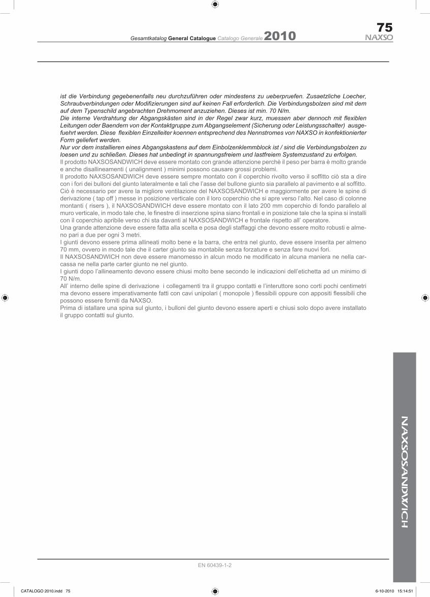
ist die Verbindung gegebenenfalls neu durchzuführen oder mindestens zu ueberpruefen. Zusaetzliche Loecher, Schraubverbindungen oder Modifizierungen sind auf keinen Fall erforderlich. Die Verbindungsbolzen sind mit dem auf dem Typenschild angebrachten Drehmoment anzuziehen. Dieses ist min. 70 N/m.Die interne Verdrahtung der Abgangskästen sind in der Regel zwar kurz, muessen aber dennoch mit flexiblen Leitungen oder Baendern von der Kontaktgruppe zum Abgangselement (Sicherung oder Leistungsschalter) ausge-fuehrt werden. Diese flexiblen Einzelleiter koennen entsprechend des Nennstromes von NAXSO in konfektionierter Form geliefert werden.Nur vor dem installieren eines Abgangskastens auf dem Einbolzenklemmblock ist / sind die Verbindungsbolzen zu loesen und zu schließen. Dieses hat unbedingt in spannungsfreiem und lastfreiem Systemzustand zu erfolgen.Il prodotto NAXSOSANDWICH deve essere montato con grande attenzione perchè il peso per barra è molto grande e anche disallineamenti ( unalignment ) minimi possono causare grossi problemi.Il prodotto NAXSOSANDWICH deve essere sempre montato con il coperchio rivolto verso il soffitto ciò sta a dire con i fori dei bulloni del giunto lateralmente e tali che l’asse del bullone giunto sia parallelo al pavimento e al soffitto. Ciò è necessario per avere la migliore ventilazione del NAXSOSANDWICH e maggiormente per avere le spine di derivazione ( tap off ) messe in posizione verticale con il loro coperchio che si apre verso l’alto. Nel caso di colonne montanti ( risers ), il NAXSOSANDWICH deve essere montato con il lato 200 mm coperchio di fondo parallelo al muro verticale, in modo tale che, le finestre di inserzione spina siano frontali e in posizione tale che la spina si installi con il coperchio apribile verso chi sta davanti al NAXSOSANDWICH e frontale rispetto all’ operatore.Una grande attenzione deve essere fatta alla scelta e posa degli staffaggi che devono essere molto robusti e alme-no pari a due per ogni 3 metri. I giunti devono essere prima allineati molto bene e la barra, che entra nel giunto, deve essere inserita per almeno 70 mm, ovvero in modo tale che il carter giunto sia montabile senza forzature e senza fare nuovi fori.Il NAXSOSANDWICH non deve essere manomesso in alcun modo ne modificato in alcuna maniera ne nella car-cassa ne nella parte carter giunto ne nel giunto.I giunti dopo l’allineamento devono essere chiusi molto bene secondo le indicazioni dell’etichetta ad un minimo di 70 N/m.All’ interno delle spine di derivazione i collegamenti tra il gruppo contatti e l’interuttore sono corti pochi centimetri ma devono essere imperativamente fatti con cavi unipolari ( monopole ) flessibili oppure con appositi flessibili che possono essere forniti da NAXSO.Prima di istallare una spina sul giunto, i bulloni del giunto devono essere aperti e chiusi solo dopo avere installato il gruppo contatti sul giunto.
CATALOGO 2010.indd 75 6-10-2010 15:14:51

2010Gesamtkatalog General Catalogue Catalogo Generale
EN 60439-1-2
76
NXW PLUG IN
NXW FEEDER
COD. AMP. A/B/C Dm3 Kg/3mt
NXW800PI 800 A 95 58
NXW1000PI 1000 A 95 61
NXW1250PI 1250 A 95 62
NXW1600PI 1600 A 120 98
NXW2000PI 2000 A 130 102
NXW2500PI 2500 B 180 168
NXW3200PI 3200 B 240 172
NXW4000PI 4000 B 260 175
NXW5000PI 5000 C 300 190
COD. AMP. A/B/C Dm3 Kg/3mt
NXW800FE 800 A 95 58
NXW1000FE 1000 A 95 61
NXW1250FE 1250 A 95 62
NXW1600FE 1600 A 120 98
NXW2000FE 2000 A 130 102
NXW2500FE 2500 B 180 168
NXW3200FE 3200 B 240 172
NXW4000FE 4000 B 260 175
NXW5000FE 5000 C 300 190
200 mm
405
mm
450
mm
200 mm
305
mm
350
mm
200 mm
155
mm
200
mm
A B C
3 mt
50A - 400A TAP-OFF
CATALOGO 2010.indd 76 6-10-2010 15:14:51
2010Gesamtkatalog General Catalogue Catalogo Generale
EN 60439-1-2
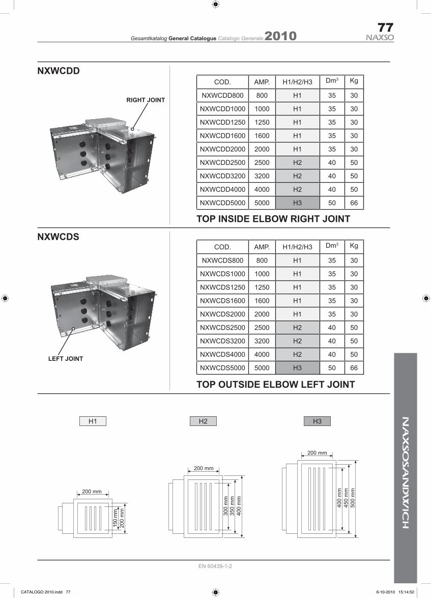
TOP INSIDE ELBOW RIGHT JOINT
TOP OUTSIDE ELBOW LEFT JOINT
77
NXWCDD
NXWCDS
COD. AMP. H1/H2/H3 Dm3 Kg
NXWCDD800 800 H1 35 30
NXWCDD1000 1000 H1 35 30
NXWCDD1250 1250 H1 35 30
NXWCDD1600 1600 H1 35 30
NXWCDD2000 2000 H1 35 30
NXWCDD2500 2500 H2 40 50
NXWCDD3200 3200 H2 40 50
NXWCDD4000 4000 H2 40 50
NXWCDD5000 5000 H3 50 66
H1 H2 H3
COD. AMP. H1/H2/H3 Dm3 Kg
NXWCDS800 800 H1 35 30
NXWCDS1000 1000 H1 35 30
NXWCDS1250 1250 H1 35 30
NXWCDS1600 1600 H1 35 30
NXWCDS2000 2000 H1 35 30
NXWCDS2500 2500 H2 40 50
NXWCDS3200 3200 H2 40 50
NXWCDS4000 4000 H2 40 50
NXWCDS5000 5000 H3 50 66
200 mm
150
mm
200
mm
200 mm
300
mm
350
mm
400
mm
200 mm
400
mm
450
mm
500
mm
RIGHT JOINT
LEFT JOINT
CATALOGO 2010.indd 77 6-10-2010 15:14:52

2010Gesamtkatalog General Catalogue Catalogo Generale
EN 60439-1-2
78
NXWCPD
NXWCPS
COD. AMP. H1/H2/H3 Dm3 Kg
NXWCPD800 800 H1 35 30
NXWCPD1000 1000 H1 35 30
NXWCPD1250 1250 H1 35 30
NXWCPD1600 1600 H1 35 30
NXWCPD2000 2000 H1 35 30
NXWCPD2500 2500 H2 40 50
NXWCPD3200 3200 H2 40 50
NXWCPD4000 4000 H2 40 50
NXWCPD5000 5000 H3 50 66
COD. AMP. H1/H2/H3 Dm3 Kg
NXWCPS800 800 H1 35 30
NXWCPS1000 1000 H1 35 30
NXWCPS1250 1250 H1 35 30
NXWCPS1600 1600 H1 35 30
NXWCPS2000 2000 H1 35 30
NXWCPS2500 2500 H2 40 50
NXWCPS3200 3200 H2 40 50
NXWCPS4000 4000 H2 40 50
NXWCPS5000 5000 H3 66 66
FRONT INSIDE ELBOW
FRONT OUTSIDE ELBOW
JOINT
JOINT
200 mm
72 m
m30
0 m
m
350
mm
500
mm
400
mm
260 mm
300 mm
400
mm
350
mm
500
mm
72 m
m500 mm
400 mm
200 mm
418
mm
72 m
m20
0 m
m15
0 m
m
200
mm
200 mm
150 mm
72 m
m
200
mm
418
mm
200
mm
200 mm
418 mm72 mm
150
mm
200 mm
CATALOGO 2010.indd 78 6-10-2010 15:14:52
2010Gesamtkatalog General Catalogue Catalogo Generale
EN 60439-1-2
79
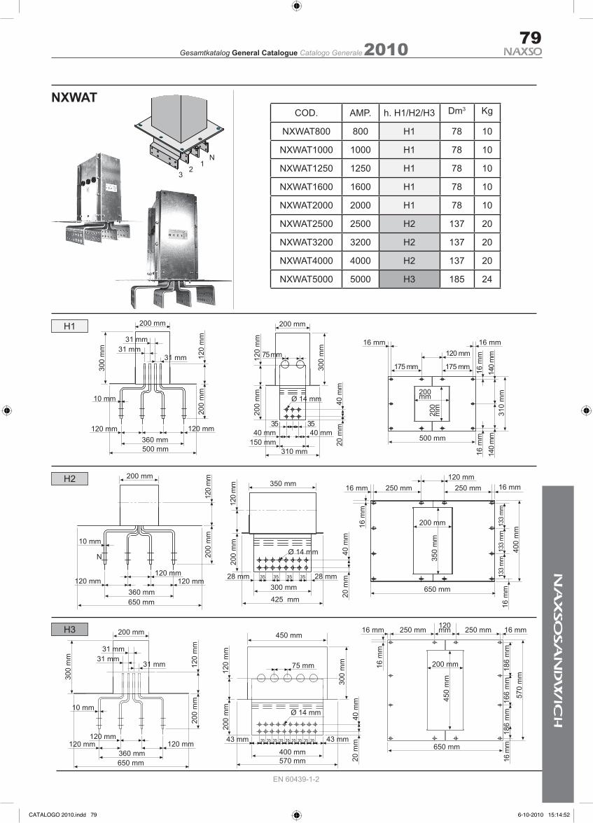
NXWATCOD. AMP. h. H1/H2/H3 Dm3 Kg
NXWAT800 800 H1 78 10
NXWAT1000 1000 H1 78 10
NXWAT1250 1250 H1 78 10
NXWAT1600 1600 H1 78 10
NXWAT2000 2000 H1 78 10
NXWAT2500 2500 H2 137 20
NXWAT3200 3200 H2 137 20
NXWAT4000 4000 H2 137 20
NXWAT5000 5000 H3 185 24
200 mm
300
mm
360 mm120 mm 120 mm
10 mm
200
mm
120
mm31 mm
31 mm31 mm
500 mm
200
mm
120
mm
200 mm30
0 m
m
75 mm
40 mm35 35
150 mm310 mm
40 mm
Ø 14 mm 40 m
m20
mm
16 m
m
16 mm120 mm
310
mm
175 mm 175 mm
16 mm
16 m
m14
0 m
m14
0 m
m500 mm
200mm
200
mm
120mm250 mm 250 mm16 mm 16 mm
16 m
m
200 mm
450
mm
650 mm
186
mm
186
mm
166
mm
570
mm
16 m
m
200 mm
300
mm
31 mm
120 mm 120 mm
10 mm
31 mm31 mm
200
mm
120
mm
360 mm650 mm
120 mm35 35 35 35
450 mm
200
mm
400 mm570 mm
43 mm 43 mm
75 mm
Ø 14 mm
300
mm
20 m
m40
mm
35 35 35 35 35
120
mm
120 mm250 mm 250 mm16 mm 16 mm
200 mm
350
mm
133
mm
400
mm
16 m
m
16 m
m
650 mm
200 mm
360 mm120 mm
120 mm120 mm
650 mm
10 mm
200
mm
120
mm
N
200
mm
350 mm
Ø 14 mm
28 mm 35 35 35 35 28 mm300 mm425 mm 20
mm
40 m
m
120
mm
133
mm
133
mm
H1
H2
H3
N1
23
CATALOGO 2010.indd 79 6-10-2010 15:14:52

2010Gesamtkatalog General Catalogue Catalogo Generale
EN 60439-1-2
80
NXWTCOD. AMP. h. H1/H2/H3 Dm3 Kg
NXWT800 800 H1 120 28
NXWT1000 1000 H1 120 40
NXWT1250 1250 H1 120 40
NXWT1600 1600 H1 140 56
NXWT2000 2000 H1 160 75
NXWT2500 2500 H2 180 85
NXWT3200 3200 H2 240 120
NXWT4000 4000 H2 260 150
NXWT5000 5000 H3 -- --
A
BC
TEES
150
mm
500 mm
350
mm
345
mm
50 mm55 mm
200 mm
265
mm
200
mm
55 mm50 mm
640 mm
495
mm
300
mm
300 mm
55 mm50 mm
55 mm50 mm
265
mm
200
mm
350 mm
CATALOGO 2010.indd 80 6-10-2010 15:14:53
2010Gesamtkatalog General Catalogue Catalogo Generale
EN 60439-1-2
81
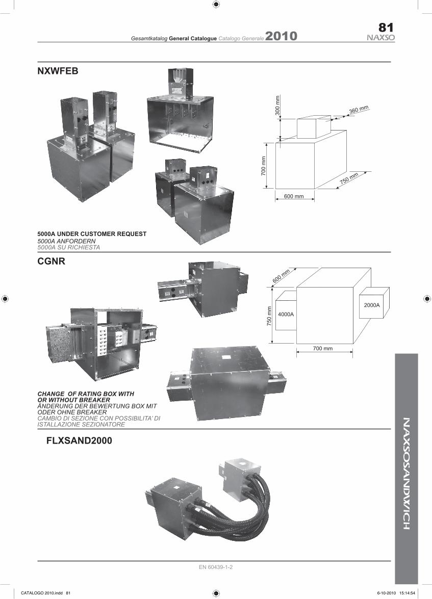
FLXSAND2000
NXWFEB
CHANGE OF RATING BOX WITHOR WITHOUT BREAKERÄNDERUNG DER BEWERTUNG BOX MIT ODER OHNE BREAKERCAMBIO DI SEZIONE CON POSSIBILITA’ DIISTALLAZIONE SEZIONATORE
CGNR
5000A UNDER CUSTOMER REQUEST5000A ANFORDERN5000A SU RICHIESTA
600 mm
700
mm
750 mm
300
mm
360 mm
700 mm
600 mm
750
mm
2000A
4000A
CATALOGO 2010.indd 81 6-10-2010 15:14:54

2010Gesamtkatalog General Catalogue Catalogo Generale
EN 60439-1-2
82
950 mm (630A)
400
mm
500 mm
FOX F / MCCB JOINT POINT PLUG-IN 630 / 800 / 1000 / 1250A
3P+N+PE
AMP 630 - 800 - 1000 - 1250A
IP 55
300,00 Dm3 (800-1000 -1250)
48,000 (800-1000 -1250)
*
39,000 (630)
200,00 Dm3 (630)
1150 mm (800A - 1000A - 1250A)
400
mm
500 mm
CATALOGO 2010.indd 82 6-10-2010 15:14:55

2010Gesamtkatalog General Catalogue Catalogo Generale
EN 60439-1-2
83
450 mm
350
mm22
0 m
m
350 mmFOX PLUG-IN 50F
40,00 Dm3
3P+N+PE
AMP 50A
IP 55
12,000
950 mm
220
mm
350 mm
650 mm
220
mm
350 mm
650 mm
220
mm
350 mm
FOX PLUG-IN 400F
FOX PLUG-IN 250F
FOX PLUG-IN 160F
105,00 Dm3
3P+N+PE
AMP 400A
IP 41 - 55
32,000
60,00 Dm3
3P+N+PE
AMP 250A
IP 55
27,000
60,00 Dm3
3P+N+PE
AMP 160A
IP 55
22,000
450 mm
350
mm22
0 m
m
350 mmFOX PLUG-IN 100F
40,00 Dm3
3P+N+PE
AMP 100A
IP 55
17,000
CATALOGO 2010.indd 83 6-10-2010 15:14:57

2010Gesamtkatalog General Catalogue Catalogo Generale
EN 60439-1-2
84
NXWATSTCOD. AMP. A x B Kg
NXWATST1250 1250 200 x 125 1,0
NXWATST1600 1600 200 x 125 1,0
NXWATST2000 2000 200 x 175 1,0
NXWATST2500 2500 200 x 195 1,5
NXWATST3200 3200 200 x 251 1,5
NXWATST4000 4000 200 x 315 1,5
NXWATST5000 5000 200 x 470 3,0
SPECIAL BRACKET FOR RISER EXSPANSION INSTALLATION CUSTOM MADE TO FIT VERTICAL AREASSTAFFA SPECIALE AD ASSORBIMENTO DILATAZIONI PER INSTALLAZIONI IN CAVEDI VERTICALI
CL
B
A
H
C = 75 - H = 50 - L = 50
CATALOGO 2010.indd 84 6-10-2010 15:14:57

2010Gesamtkatalog General Catalogue Catalogo Generale
EN 60439-1-2
85
FIRE BARIER / FEUER BARIÉR BARRIERA TAGLIAFUOCO
Fire barrier testFeuer barriér testTest barriera tagliafuoco
50 mm
PROMATECT 500
PROMASEAL G
CATALOGO 2010.indd 85 6-10-2010 15:14:58


2010Gesamtkatalog General Catalogue Catalogo Generale88
EN 60439-1-2
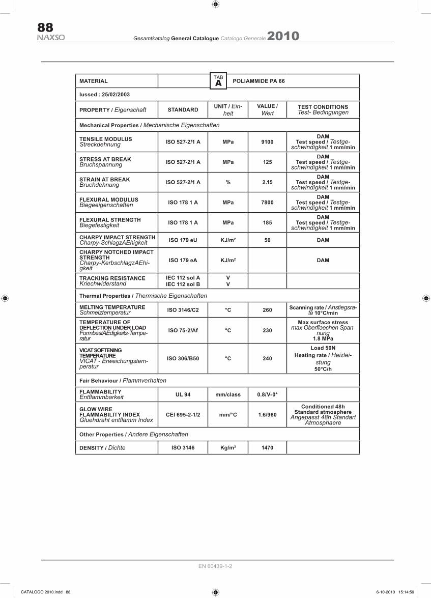
MATERIAL POLIAMMIDE PA 66
Iussed : 25/02/2003
PROPERTY / Eigenschaft STANDARD UNIT / Ein-heit
VALUE / Wert
TEST CONDITIONSTest- Bedingungen
Mechanical Properties / Mechanische Eigenschaften
TENSILE MODULUS Streckdehnung ISO 527-2/1 A MPa 9100
DAMTest speed / Testge-
schwindigkeit 1 mm/min
STRESS AT BREAKBruchspannung ISO 527-2/1 A MPa 125
DAMTest speed / Testge-
schwindigkeit 1 mm/min
STRAIN AT BREAKBruchdehnung ISO 527-2/1 A % 2.15
DAMTest speed / Testge-
schwindigkeit 1 mm/min
FLEXURAL MODULUSBiegeeigenschaften ISO 178 1 A MPa 7800
DAMTest speed / Testge-
schwindigkeit 1 mm/min
FLEXURAL STRENGTHBiegefestigkeit ISO 178 1 A MPa 185
DAMTest speed / Testge-
schwindigkeit 1 mm/minCHARPY IMPACT STRENGTHCharpy-SchlagzAEhigkeit ISO 179 eU KJ/m2 50 DAM
CHARPY NOTCHED IMPACT STRENGTHCharpy-KerbschlagzAEhi-gkeit
ISO 179 eA KJ/m2 DAM
TRACKING RESISTANCEKriechwiderstand
IEC 112 sol AIEC 112 sol B
VV
Thermal Properties / Thermische Eigenschaften
MELTING TEMPERATURESchmelztemperatur ISO 3146/C2 °C 260 Scanning rate / Anstiegsra-
te 10°C/minTEMPERATURE OFDEFLECTION UNDER LOADFormbestAEdigkeits-Tempe-ratur
ISO 75-2/Af °C 230Max surface stress
max Oberflaechen Span-nung
1.8 MPa
VICAT SOFTENINGTEMPERATUREVICAT - Erweichungstem-peratur
ISO 306/B50 °C 240
Load 50NHeating rate / Heizlei-
stung 50°C/h
Fair Behaviour / Flammverhalten
FLAMMABILITYEntflammbarkeit UL 94 mm/class 0.8/V-0*
GLOW WIREFLAMMABILITY INDEXGluehdraht entflamm Index
CEI 695-2-1/2 mm/°C 1.6/960Conditioned 48h
Standard atmosphereAngepasst 48h Standart
Atmosphaere
Other Properties / Andere Eigenschaften
DENSITY / Dichte ISO 3146 Kg/m3 1470
CATALOGO 2010.indd 88 6-10-2010 15:14:59
2010Gesamtkatalog General Catalogue Catalogo Generale89
EN 60439-1-2
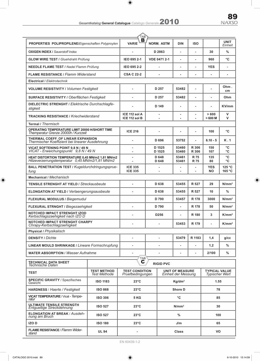
PROPERTIES POLIPROPILENE/Eigenschaften Polyproylen VARIE NORM. ASTM DIN ISO UNITEinheit
OXIGEN INDEX / Sauerstoff Index - D 2863 - - 30 %
GLOW WIRE TEST / Gluehdraht Prüfung IEO 695 2-1 VDE 0471 2-1 - - 960 °C
NEEDLE FLAME TEST / Nadel Flamm Prüfung IEO 695 2-2 - - - YES -
FLAME RESISTANCE / Flamm Widerstand CSA C 22-2 - - - - -
Electrical / Elektrotechnik
VOLUME RESISTIVITY / Volumen Festigkeit - D 257 53482 - - Ohm . cm
SURFACE RESISTIVITY / Oberflächen Festigkeit - D 257 53482 - - Ohm
DIELECTRIC STRENGHT / Elektrische Durchschlagfe-stigkeit - D 149 - - - KV/mm
TRACKING RESISTANCE / Kriechwiderstand ICE 112 sol AICE 112 sol B
--
--
--
> 600> 600 M
VV
Termal / ThermischOPERATING TEMPERATURE LIMIT 20000 H/SHORT TIMEThemperatur Grenze 20000h / Kurzzeit ICE 216 - - - 100 °C
THERMAL COEFF. OF LINEAR EXPANSIONThermischer Koeffizient bei linearer Ausdehnung - D 696 53752 - 6.10 - 5 K . 1
VICAT SOFTENING POINT 9,8 N / 49 NVICAT - Erweichungspunkt 9,8 N / 49 N
--
D 1525D 1525
5346053460
R 306R 306
150107
°C°C
HEAT DISTORTION TEMPERATURE 0,45 MN/m2 1,81 MN/m2Hitzeverzerrungstemperatur 0,45 MN/m2/1,81 MN/m2
--
D 648D 648
5346153461
R 75R 75
13580
°C°C
BALL PENETRATION TEST / Kugeldurchdringungsprue-fung
ICE 335ICE 335
--
--
--
YESNO
125 °C165 °C
Mechanical / Mechanisch
TENSILE STRENGHT AT YIELD / Streckausbeute - D 638 53455 R 527 29 N/mm2
ELONGATION AT YIELD / Verlaengerungsausbeute - D 638 53455 R 527 10 %
FLEXURAL MODULUS / Biegemudul D 790 53457 R 178 3000 N/mm2
FLEXURAL STRNGHT / Biegezaehigkeit - D 790 - R 178 50 N/mm2
NOTCHED IMPACT STRENGHT IZODKerbschlagszaehigkeit nach IZO D - D256 - R 180 3 K/mm2
NOTCHED IMPACT STRENGHT CHARPYChrapy-Kerbschlagzaehigkeit - - 53453 R 179 - K/mm2
Physical / Physikalisch
DENSITY / Dichte - - 53479 R 1183 1,4 g/cc
LINEAR MOULD SHRINKAGE / Lineare Formschrupfung - - - - 1,2 %
WATER ABSORPTION / Wasser Aufnahme - - - - 2/100 %
TECHNICAL DATA SHEETTechnische Daten RIGID PVC
TEST TEST METHODTest Methode
TEST CONDITIONPruefbedingungen
UNIT OF MEASUREEinheit der Messung
TYPICAL VALUETypischer Wert
SPECIFIC GRAVITY / Spezifisches Gewicht ISO 1183 23°C Kg/dm3 1.55
HARDNESS / Haerte / Festigkeit ISO 868 23°C Shore D 78
VICAT TEMPERATURE / Vicat - Tempe-ratur ISO 306 5 KG °C 85
ULTIMATE TENSILE STRENGTHEntgueltige Streckdehnung ISO 527 23°C N/mm2 30
ELONGATION AT BREAK / Ausdeh-nung am Bruch ISO 527 23°C % 100
IZO D ISO 180 23°C J/m 65
FLAME RESISTANCE / Flamm Wider-stand UL 94 - Class VO
CATALOGO 2010.indd 89 6-10-2010 15:14:59

2010Gesamtkatalog General Catalogue Catalogo Generale90
EN 60439-1-2
COMPOSIZIONE CHIMICA PERCENTUALEMg Si Fe Ti Cu Cr Mn Zn Altri elementi max Al
0,35-0,60 0,30-0,60 0,10-0,30 0,10 0,10 0,05 0,10 0,15 0,05-0,15 97,9CARATTERISTICHE PRINCIPALI
Estrudibilità eccellente. Lega di media durezza adatta per estrusi difficili. Alta resistenza alla corrosione. Buona formabilità allo stato TaN. Buona finitura superficiale. Saldabilità buona.
USI TIPICI Applicazioni architettoniche e decorative. Profili per serramenti. Industria chimica.
CARATTERISTICHE FISICHE E GENERALI Peso specifico 2,7 kg/dm3 Calore specifico 0 -100 °C ≈ 0,92 J (g.k) Modulo di elasticità 66000 N/mm2 Coeff. di dilatazione Modulo di rigidità 26500 N/mm2 teorico lineare 20 -100 °C 23 x 10-6 x K-1
Punto di fusione 605 °C Conduttività termica 20 °C ≈ 1,75 W (cm x k) Resistance a 20 °C (T6) ≈ 3,25 μ Ω x cm Lega EN AW-6060 (Al MgSi) BARRA ESTRUSA CARICO DI ROTTURA CARICO AL LIMITE ALLUNGAMENTO A TRAZIONE DI SNERVAMENTO
Stato metallurgicoDimensioni mm Rm MPa Rp 0,2 MPa A % A 50 mm %D1) S2) min max min max min min
T45) ≤ 150 ≤ 150 120 - 60 - 16 14T5 ≤ 150 ≤ 150 160 - 120 - 8 6T65) ≤ 150 ≤ 150 190 - 150 - 8 6
TUBO ESTRUSO CARICO DI ROTTURA CARICO AL LIMITE ALLUNGAMENTO A TRAZIONE DI SNERVAMENTO
Stato metallurgico Dimensioni mm e3)Rm MPa Rp 0,2 MPa A % A 50 mm %
min max min max min minT45) ≤ 15 120 - 60 - 16 14T5 ≤ 15 160 - 120 - 8 6T65) ≤ 15 190 - 150 - 8 6
PROFILATO ESTRUSO10) CARICO DI ROTTURA CARICO AL LIMITE ALLUNGAMENTO A TRAZIONE DI SNERVAMENTO
Stato metallurgico Dimensioni mm e3)Rm MPa Rp 0,2 MPa A % A 50 mm %
min max min max min minT45) ≤ 25 120 - 60 - 16 14
≤ 5 160 - 120 - 8 6
T5 5 < e ≤ 25 140 - 100 - 8 6
≤ 3 190 - 150 - 8 6
T65) 3 < e ≤ 25 170 - 140 - 8 6
EN AW-AIMgSi UNI EN 573-3 (6060)
CATALOGO 2010.indd 90 6-10-2010 15:14:59
2010Gesamtkatalog General Catalogue Catalogo Generale91
EN 60439-1-2
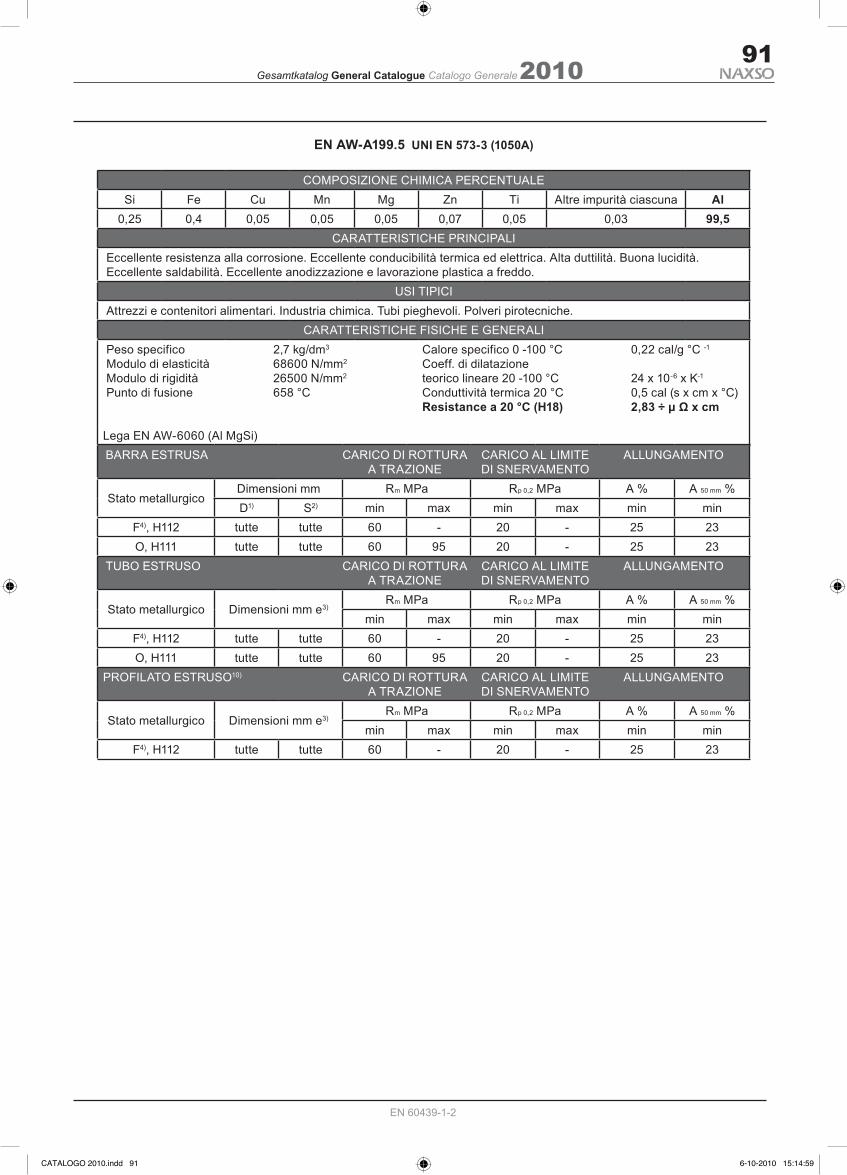
COMPOSIZIONE CHIMICA PERCENTUALESi Fe Cu Mn Mg Zn Ti Altre impurità ciascuna Al
0,25 0,4 0,05 0,05 0,05 0,07 0,05 0,03 99,5CARATTERISTICHE PRINCIPALI
Eccellente resistenza alla corrosione. Eccellente conducibilità termica ed elettrica. Alta duttilità. Buona lucidità. Eccellente saldabilità. Eccellente anodizzazione e lavorazione plastica a freddo.
USI TIPICI Attrezzi e contenitori alimentari. Industria chimica. Tubi pieghevoli. Polveri pirotecniche.
CARATTERISTICHE FISICHE E GENERALI Peso specifico 2,7 kg/dm3 Calore specifico 0 -100 °C 0,22 cal/g °C -1
Modulo di elasticità 68600 N/mm2 Coeff. di dilatazione Modulo di rigidità 26500 N/mm2 teorico lineare 20 -100 °C 24 x 10-6 x K-1
Punto di fusione 658 °C Conduttività termica 20 °C 0,5 cal (s x cm x °C) Resistance a 20 °C (H18) 2,83 ÷ μ Ω x cm Lega EN AW-6060 (Al MgSi) BARRA ESTRUSA CARICO DI ROTTURA CARICO AL LIMITE ALLUNGAMENTO A TRAZIONE DI SNERVAMENTO
Stato metallurgicoDimensioni mm Rm MPa Rp 0,2 MPa A % A 50 mm %D1) S2) min max min max min min
F4), H112 tutte tutte 60 - 20 - 25 23O, H111 tutte tutte 60 95 20 - 25 23
TUBO ESTRUSO CARICO DI ROTTURA CARICO AL LIMITE ALLUNGAMENTO A TRAZIONE DI SNERVAMENTO
Stato metallurgico Dimensioni mm e3)Rm MPa Rp 0,2 MPa A % A 50 mm %
min max min max min minF4), H112 tutte tutte 60 - 20 - 25 23O, H111 tutte tutte 60 95 20 - 25 23
PROFILATO ESTRUSO10) CARICO DI ROTTURA CARICO AL LIMITE ALLUNGAMENTO A TRAZIONE DI SNERVAMENTO
Stato metallurgico Dimensioni mm e3)Rm MPa Rp 0,2 MPa A % A 50 mm %
min max min max min minF4), H112 tutte tutte 60 - 20 - 25 23
EN AW-A199.5 UNI EN 573-3 (1050A)
CATALOGO 2010.indd 91 6-10-2010 15:14:59

2010Gesamtkatalog General Catalogue Catalogo Generale92
EN 60439-1-2
PROZENTUALER ANTEIL DER ZUSATZSTOFFEMg Si Fe Ti Cu Cr Mn Zn Zusatzstoffe max Al
0,35-0,60 0,30-0,60 0,10-0,30 0,10 0,10 0,05 0,10 0,15 0,05-0,15 97,9CHARAKTERISTISCHE GESAMTEIGENSCHAFTEN
Gute Extrudierbarkeit. Legierung mittlerer Haerte fuer besondere Extrudierung. Erweiterte Korrosionsbestaendigkeit. Gute Formbarkeit und Festigkeit nach TaN. Gute Oberflaechen Beschaffenheit. Gute schweiss Eigenschaften.
TYPISCHE NUTZUNG / VERWENDUNG Verwendung in Bauten und zu dekorativen Zwecken. Profile fuer gekapselten Einbau. Verwendung in der chemischen Industrie.
CHARAKTERISTISCHE PHYSIKALISCHE EIGENSCHAFTEN Gewicht 2,7 kg/dm3 Spezifische Waerme 0 -100 °C ≈ 0,92 J (g.k) Elastizitaetsmodul (E) 66000 N/mm2 Waermeausdehnungskoeffizient Festigkeitsmodul 26500 N/mm2 Theoretische Gerade 20 -100 °C 23 x 10-6 x K-1 Schmelzpunkt 605 °C Verlustleistung bei 20 °C ≈ 1,75 W (cm x k) Widerstand bei 20 °C (T6) ≈ 3,25 μ Ω x cm Lega EN AW-6060 (Al MgSi)
EN AW-AIMgSi UNI EN 573-3 (6060)
PROZENTUALER ANTEIL DER ZUSATZSTOFFESi Fe Cu Mn Mg Zn Ti Altre impurità ciascuna Al
0,25 0,4 0,05 0,05 0,05 0,07 0,05 0,03 99,5CHARAKTERISTISCHE GESAMTEIGENSCHAFTEN
Besondere Korrosionsbestaendigkeit. Besondere thermische und elektrische Leitfaehigkeit. Hervorragende Dehnbarkeit. Besonderer Materialglanz. Sehr gute Schweisseigenschaften. Gute Eloxierbarkeit und mechanische Bearbeitung.
TYPISCHE NUTZUNG / VERWENDUNG Verpackungen und Werkzeuge in Verbindung mit Lebensmitteln. In der chemischen Industrie. Flexible Schlaeuche und Rohrei. Bei pyrotechnischen Pulvern.
CHARAKTERISTISCHE PHYSIKALISCHE EIGENSCHAFTEN Gewicht 2,7 kg/dm3 Spezifische Waerme 0 -100 °C 0,22 cal/g °C-1 Elastizitaetsmodul (E) 68600 N/mm2 Waermeausdehnungskoeffizient Festigkeitsmodul 26500 N/mm2 Theoretische Gerade 20 -100 °C 24 x 10-6 x K-1 Schmelzpunkt 658 °C Verlustleistung bei 20 °C 0,5 cal (s x cm x °C) Widerstand bei °C (H18) 2,83÷2,90 μ Ω x cm Lega EN AW-6060 (Al MgSi)
EN AW-A199.5 UNI EN 573-3 (1050A)
CATALOGO 2010.indd 92 6-10-2010 15:14:59

2010Gesamtkatalog General Catalogue Catalogo Generale93
EN 60439-1-2
CATALOGO 2010.indd 93 6-10-2010 15:15:00

2010Gesamtkatalog General Catalogue Catalogo Generale94
EN 60439-1-2
CATALOGO 2010.indd 94 6-10-2010 15:15:00

2010Gesamtkatalog General Catalogue Catalogo Generale95
EN 60439-1-2
CATALOGO 2010.indd 95 6-10-2010 15:15:00

2010Gesamtkatalog General Catalogue Catalogo Generale96
EN 60439-1-2
Misty test is provided to compare different kind of surface protections. The test is runned putting in the same humid and salty room for 96 hours different materials and at the end a visual ceck isrequired to de-scribe the results.It is possible to see how the standard aluminium can stand the humidity with some little rusty stains as well as the andized one is strong and excellent when the housing is under hard conditions and at the end how standard steel even if galvanized have a very poor resistance against humidity.
Korrosionstest in saltziger AtmosphaereSample n° 1: Standard Stahlblech verzinktSample n° 2: Standard Naxso Alluminium Sample n° 3: Standard Alluminium eloxiert
La prova suddetta dimostra la resistenza del prodotto all’ aggressione derivante dalla esposizione alla umidità in un clima salino corrosivo per una durata di 96 ore (primo ciclo) e 288 ore (secondo ciclo). Dopo questi test i prodotti non devono presentare danneggiamenti significativi.Dalla foto riportata dal test eseguito presso l’IMQ si vede il risultato comparativo, come previsto dalla norma, tra un campione di materiale sendzimir, un campione di alluminio standard NAXSOLUX ed uno anodizzato.Il campione in metallo dopo la prova è completamente corroso mentre quello in alluminio standard è appena intac-cato da macchie superficiali ed infine quello in alluminio anodizzato è risultato completamente indifferente all’ag-gressione della nebbia salina.
CATALOGO 2010.indd 96 6-10-2010 15:15:00

2010Gesamtkatalog General Catalogue Catalogo Generale97
EN 60439-1-2
DECLARATION OF EC CONFORMITYDICHIARAZIONE DI CONFORMITÀ
No. TL/Prot20209
The product / Prodotto
Type reference / Sigla prodotto Naxsolux 25A - 40A - 63A Serie BA - serie BM
Supplier / Fornitore Naxso Srl 10135 TORINO (I)
Description / Descrizione Light Busbar trunking system Condotto barre prefabbricato
To which this declaration relates is in conformity with the following standard:L’ oggetto di questa dichiarazione è conforme ai seguenti standard o normative:
Standard / Norme: CEI 17/13-1-2 CEI EN 60439/1-2 CEI EN 61000-2-4 (CEI 110-27) DIN VDE 0660 parte 500-502 CEI EN 60068-2-11:2000 Class CEI 104-17-F.5890
Type tests / Prove di Tipo
1. Temperature-rise limits 1.Tenuta alla tensione applicata2. Dielectric properties 2.Limiti di sovratemperatura3. Short-circuit strength 3.Efficienza del circuito di protezione4. Effectiveness of the protective circuit 4.Tenuta al cortocircuito5. Clearances and creepage distances 5.Cablaggio, funzionamento elettrico6. Mechanical operation 6.Grado di protezione7. Degree of protection 7.Funzionamento8. Electrical characteristics 8.Distanze in aria e superficiali9. Structural strength 9. Isolamento10. Crushing resistance 10.Resistenza di isolamento11. Resistance to flame propagation 11.Misure di protezione12. Fire barrier in building penetration 12. Barriera tagliafuoco
This declaration of Conformity according to EN 45014, was issued after tests in laboratory.Questa dichiarazione di conformità, come disposto dalla Normativa EN 60439, è stata emessadopo aver effettuato test nei laboratori dell’ Istituto IMQ, in data 27 Giugno 2001.
Date of issue / Data NAXSO S.r.l. 22/05/2008
CATALOGO 2010.indd 97 6-10-2010 15:15:00

2010Gesamtkatalog General Catalogue Catalogo Generale98
EN 60439-1-2
DECLARATION OF EC CONFORMITYDICHIARAZIONE DI CONFORMITÀ
No. TL/Prot20210
The product / Prodotto
Type reference / Sigla prodotto Naxsopower BP 40A - 63A - 100A - 160A Naxsopower BPK 250A - 315A - 400A Naxsopower BPG 250A - 400A - 500A - 630A Naxsopower BPGG 800A - 1000A
Supplier / Fornitore Naxso Srl 10135 TORINO (I)
Description / Descrizione Light Busbar trunking system Condotto barre prefabbricato
To which this declaration relates is in conformity with the following standard:L’ oggetto di questa dichiarazione è conforme ai seguenti standard o normative:
Standard / Norme: CEI 17/13-1-2 CEI EN 60439/1-2 CEI EN 61000-2-4 (CEI 110-27) DIN VDE 0660 parte 500-502 CEI EN 60068-2-11:2000 Class CEI 104-17-F.5890
Type tests / Prove di Tipo
1. Temperature-rise limits 1.Tenuta alla tensione applicata2. Dielectric properties 2.Limiti di sovratemperatura3. Short-circuit strength 3.Efficienza del circuito di protezione4. Effectiveness of the protective circuit 4.Tenuta al cortocircuito5. Clearances and creepage distances 5.Cablaggio, funzionamento elettrico6. Mechanical operation 6.Grado di protezione7. Degree of protection 7.Funzionamento8. Electrical characteristics 8.Distanze in aria e superficiali9. Structural strength 9. Isolamento10. Crushing resistance 10.Resistenza di isolamento11. Resistance to flame propagation 11.Misure di protezione12. Fire barrier in building penetration 12. Barriera tagliafuoco
This declaration of Conformity according to EN 45014, was issued after tests in laboratory.Questa dichiarazione di conformità, come disposto dalla Normativa EN 60439, è stata emessadopo aver effettuato test nei laboratori dell’ Istituto IMQ, in data 27 Giugno 2001.
Date of issue / Data NAXSO S.r.l. 10/07/2008
CATALOGO 2010.indd 98 6-10-2010 15:15:00

2010Gesamtkatalog General Catalogue Catalogo Generale99
EN 60439-1-2
DECLARATION OF EC CONFORMITYDICHIARAZIONE DI CONFORMITÀ
No. TL/Prot20221
The product / Prodotto
Type reference / Sigla prodotto Naxsosandwich 800A - 1000A - 1250A - 1600A 2000A - 2500A - 3200A - 4000A - 5000A
Supplier / Fornitore Naxso Srl 10135 TORINO (I)
Description / Descrizione Light Busbar trunking system Condotto barre prefabbricato
To which this declaration relates is in conformity with the following standard:L’ oggetto di questa dichiarazione è conforme ai seguenti standard o normative:
Standard / Norme: CEI 17/13-1-2 CEI EN 60439/1-2 CEI EN 61000-2-4 (CEI 110-27) DIN VDE 0660 parte 500-502 CEI EN 60068-2-11:2000 Class CEI 104-17-F.5890
Type tests / Prove di Tipo
1. Temperature-rise limits 1.Tenuta alla tensione applicata2. Dielectric properties 2.Limiti di sovratemperatura3. Short-circuit strength 3.Efficienza del circuito di protezione4. Effectiveness of the protective circuit 4.Tenuta al cortocircuito5. Clearances and creepage distances 5.Cablaggio, funzionamento elettrico6. Mechanical operation 6.Grado di protezione7. Degree of protection 7.Funzionamento8. Electrical characteristics 8.Distanze in aria e superficiali9. Structural strength 9. Isolamento10. Crushing resistance 10.Resistenza di isolamento11. Resistance to flame propagation 11.Misure di protezione12. Fire barrier in building penetration 12. Barriera tagliafuoco
This declaration of Conformity according to EN 45014, was issued after tests in laboratory.Questa dichiarazione di conformità, come disposto dalla Normativa EN 60439, è stata emessadopo aver effettuato test nei laboratori dell’ Istituto IMQ, in data 27 Giugno 2001.
Date of issue / Data NAXSO S.r.l. 18/06/2008
CATALOGO 2010.indd 99 6-10-2010 15:15:01
2010Gesamtkatalog General Catalogue Catalogo Generale100
EN 60439-1-2
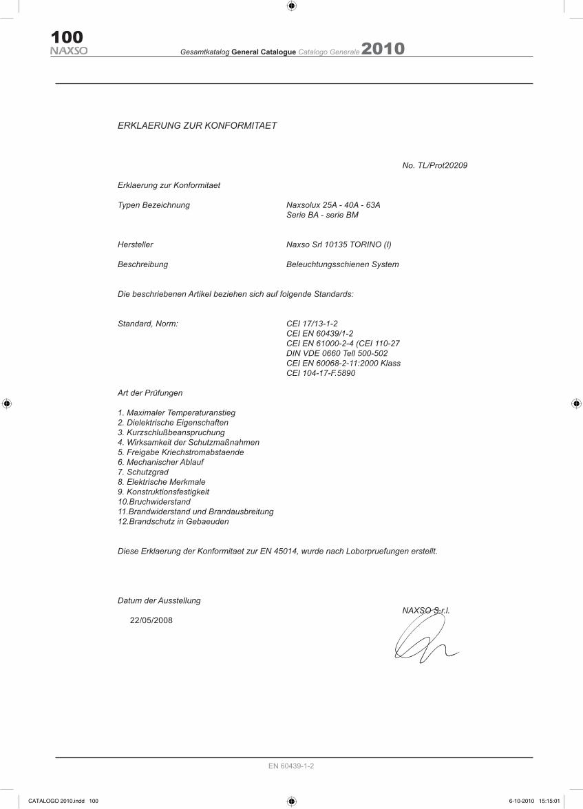
ERKLAERUNG ZUR KONFORMITAET
No. TL/Prot20209
Erklaerung zur Konformitaet
Typen Bezeichnung Naxsolux 25A - 40A - 63A Serie BA - serie BM
Hersteller Naxso Srl 10135 TORINO (I) Beschreibung Beleuchtungsschienen System
Die beschriebenen Artikel beziehen sich auf folgende Standards:
Standard, Norm: CEI 17/13-1-2 CEI EN 60439/1-2 CEI EN 61000-2-4 (CEI 110-27 DIN VDE 0660 Tell 500-502 CEI EN 60068-2-11:2000 Klass CEI 104-17-F.5890
Art der Prüfungen
1. Maximaler Temperaturanstieg2. Dielektrische Eigenschaften3. Kurzschlußbeanspruchung4. Wirksamkeit der Schutzmaßnahmen5. Freigabe Kriechstromabstaende6. Mechanischer Ablauf7. Schutzgrad8. Elektrische Merkmale9. Konstruktionsfestigkeit10.Bruchwiderstand11.Brandwiderstand und Brandausbreitung12.Brandschutz in Gebaeuden
Diese Erklaerung der Konformitaet zur EN 45014, wurde nach Loborpruefungen erstellt.
Datum der Ausstellung NAXSO S.r.l. 22/05/2008
CATALOGO 2010.indd 100 6-10-2010 15:15:01

2010Gesamtkatalog General Catalogue Catalogo Generale101
EN 60439-1-2
ERKLAERUNG ZUR KONFORMITAET
No. TL/Prot20210
Erklaerung zur Konformitaet
Typen Bezeichnung Naxsopower BP 40A - 63A - 100A - 160A Naxsopower BPK 250A - 315A - 400A Naxsopower BPG 250A - 400A - 500A - 630A Naxsopower BPGG 800A - 1000A Hersteller Naxso Srl 10135 TORINO (I)
Beschreibung Stromschienen System
Die beschriebenen Artikel beziehen sich auf folgende Standards:
Standard, Norm: CEI 17/13-1-2 CEI EN 60439/1-2 CEI EN 61000-2-4 (CEI 110-27 DIN VDE 0660 Tell 500-502 CEI EN 60068-2-11:2000 Klass CEI 104-17-F.5890
Art der Prüfungen
1. Maximaler Temperaturanstieg2. Dielektrische Eigenschaften3. Kurzschlußbeanspruchung4. Wirksamkeit der Schutzmaßnahmen5. Freigabe Kriechstromabstaende6. Mechanischer Ablauf7. Schutzgrad8. Elektrische Merkmale9. Konstruktionsfestigkeit10.Bruchwiderstand11.Brandwiderstand und Brandausbreitung12.Brandschutz in Gebaeuden
Diese Erklaerung der Konformitaet zur EN 45014, wurde nach Loborpruefungen erstellt.
Datum der Ausstellung NAXSO S.r.l. 10/07/2008
CATALOGO 2010.indd 101 6-10-2010 15:15:01

2010Gesamtkatalog General Catalogue Catalogo Generale102
EN 60439-1-2
ERKLAERUNG ZUR KONFORMITAET
No. TL/Prot20209 Erklaerung zur Konformitaet
Typen Bezeichnung Naxsosandwich 800A - 1000A - 1250A - 1600A - 2000A 2500A - 3200A - 4000A - 5000A
Hersteller Naxso Srl 10135 TORINO (I)
Beschreibung Stromschienen System
Die beschriebenen Artikel beziehen sich auf folgende Standards:
Standard, Norm: CEI 17/13-1-2 CEI EN 60439/1-2 CEI EN 61000-2-4 (CEI 110-27 DIN VDE 0660 Tell 500-502 CEI EN 60068-2-11:2000 Klass CEI 104-17-F.5890
Art der Prüfungen
1. Maximaler Temperaturanstieg2. Dielektrische Eigenschaften3. Kurzschlußbeanspruchung4. Wirksamkeit der Schutzmaßnahmen5. Freigabe Kriechstromabstaende6. Mechanischer Ablauf7. Schutzgrad8. Elektrische Merkmale9. Konstruktionsfestigkeit10.Bruchwiderstand11.Brandwiderstand und Brandausbreitung12.Brandschutz in Gebaeuden
Diese Erklaerung der Konformitaet zur EN 45014, wurde nach Loborpruefungen erstellt.
Datum der Ausstellung NAXSO S.r.l. 18/06/2008
CATALOGO 2010.indd 102 6-10-2010 15:15:01

CATALOGO 2010.indd 103 6-10-2010 15:15:01


CATALOGO 2010.indd 109 6-10-2010 15:15:02
2010Gesamtkatalog General Catalogue Catalogo Generale110
EN 60439-1-2
ANCE CERTIFICATION
CATALOGO 2010.indd 110 6-10-2010 15:15:03

2010Gesamtkatalog General Catalogue Catalogo Generale111
EN 60439-1-2
ANCE CERTIFICATION
CATALOGO 2010.indd 111 6-10-2010 15:15:03

CATALOGO 2010.indd 112 6-10-2010 15:15:03