navigate user guide - d2r72yk5wmppdj.cloudfront.net
TRANSCRIPT
teknion navigateuser guide
navigateuser guide
teknion navigateuser guide
2
disclaimer
servicing of double-insulatedproducts
Important Safety Instructions
Read all instructions before using this furnishing.
When using an electrical furnishing, basic precautions should always be followed, including the following:
DANGER – To reduce the risk of electric shock:1. Always unplug this furnishing from the electrical outlet before cleaning.
WARNING – To reduce the risk of burns, fire, electric shock, or injury to persons:2. Unplug from outlet before putting on or taking off parts.3. Close supervision is necessary when this furnishing is used by, or near children, invalids, or disabled persons.4. Use this furnishing only for its intended use as described in these instructions. Do not use attachments not recommended by the manufacturer.5. Never operate this furnishing if it has a damaged cord or plug, if it is not working properly, if it has been dropped or damaged, or dropped into water. Return the furnishing to a service center for examination and repair.6. Keep the cord away from heated surfaces.7. Do not use outdoors.8. Do not operate where aerosol (spray) products are being used or where oxygen is being administered.9. “WARNING: Risk of Injury – Keep children away from elevated table surface”10. Maximum intended load for 2-leg table surface 200 lbs.11. Maximum intended load for 3-leg table surface 300 lbs.
SAVE THESE INSTRUCTIONS
In a double-insulated product, two systems of insulation are provided instead of grounding. No grounding means is provided on a double-insulated product, nor is a means for grounding to be added to the product. Servic-ing a double insulated product requires extreme care and knowledge of the system, and is to be done only by qualified service personnel. Replacement parts for a double-insulated product must be identical to the parts they replace. A double insulated product is marked with the words ″DOUBLE INSULATION″ or ″DOUBLE INSULATED.″ The symbol (square within a square) is also able to be marked on the product.
0

teknion navigateuser guide
3Table of Contents
• List of Error Codes
• Switch Anatomy
navigate switchfunctionality
cerebro / lightbar ic functionality
error codes
switch anatomy
• Start up• Display Dashboard • Up/Down• Active/Resting State• Bluetooth Pairing • Reaching Memory Settings• Saving Memory Settings • Clearing Individual Memory Settings • Clearing All Memory Settings• Error Codes
• Initialize • Factory Reset • Units/Offset Mode • Reminder Settings Selection• Timers• Posture Change• End of Cycle• Canceling Reminders at any Time • Comprehensive Switch Anatomy
pages 05 - 11
pages 17 - 23
page 04
• Lightbar Anatomy• Cerebro/Lightbar IC Logic• Initial Storing Monitor Height• Moving to Stored Memory Settings• Switch Release Before Memory Settings
page 12-16
important safety instructions • Disclaimer
• Servicing of Double-Insulated Products
page 02
0
teknion navigateuser guide
4
switch anatomy
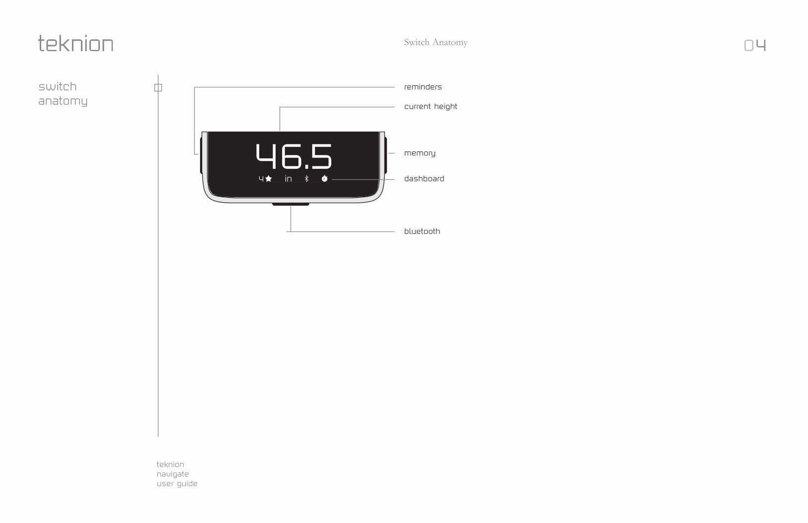
Switch Anatomy
46.5in4
reminders
current height
memory
dashboard
bluetooth
0
teknion navigateuser guide
5
46.5 46.5in4
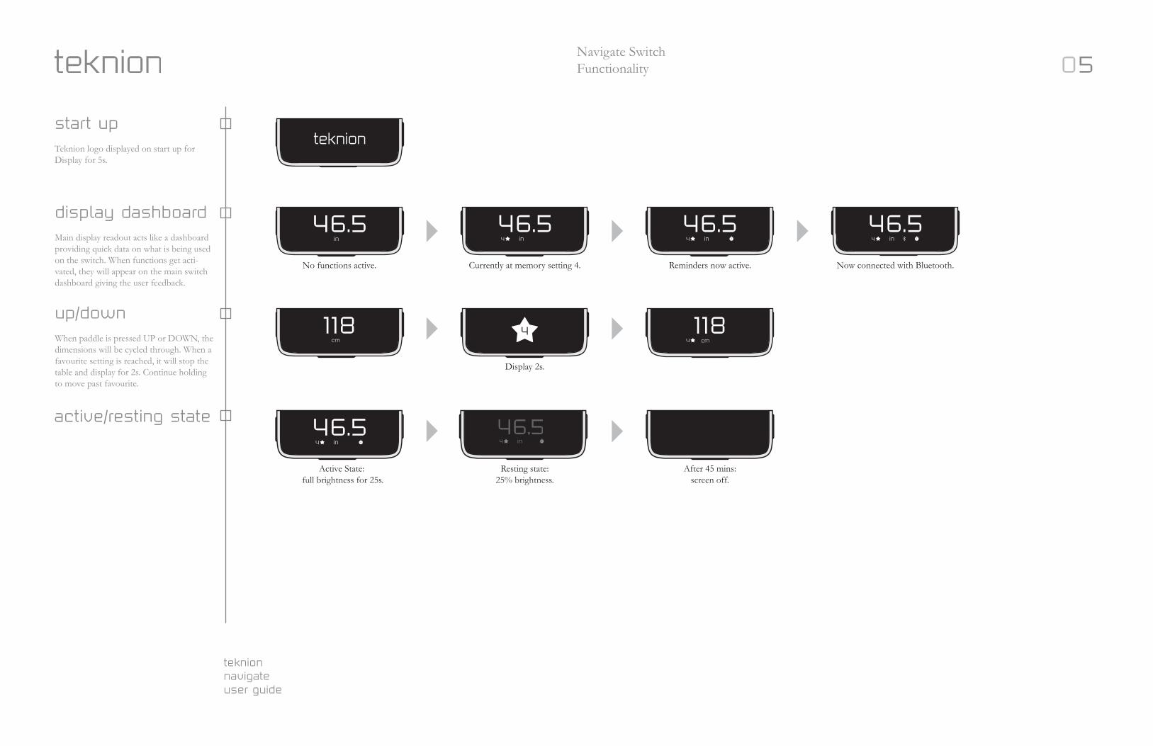
46.546.5No functions active. Currently at memory setting 4.
Display 2s.
Active State: full brightness for 25s.
Resting state: 25% brightness.
After 45 mins: screen off.
Reminders now active. Now connected with Bluetooth.
start up Teknion logo displayed on start up for Display for 5s.
display dashboard Main display readout acts like a dashboard providing quick data on what is being used on the switch. When functions get acti-vated, they will appear on the main switch dashboard giving the user feedback.
up/downWhen paddle is pressed UP or DOWN, the dimensions will be cycled through. When a favourite setting is reached, it will stop the table and display for 2s. Continue holding to move past favourite.
active/resting state
118 1184
46.5 .465
Navigate SwitchFunctionality
in in4 in4
4 cmcm
in4 in4
0
teknion navigateuser guide
6
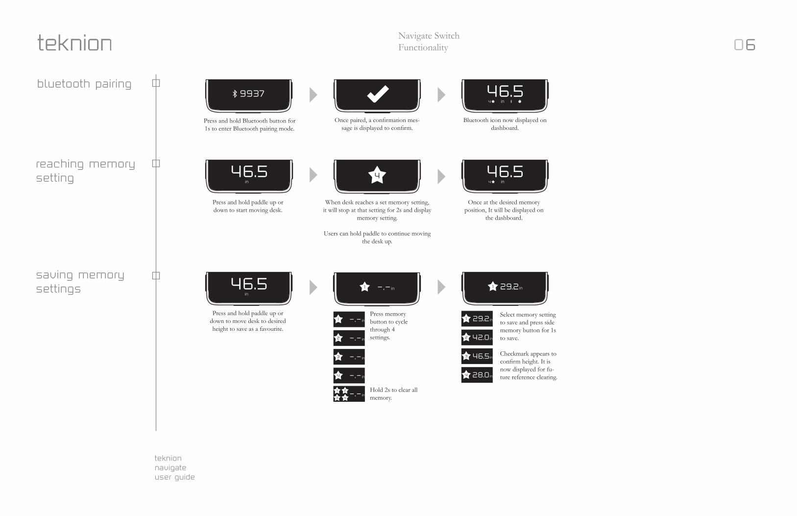
Press and hold paddle up or down to move desk to desired height to save as a favourite.
Press memory button to cycle through 4 settings.
Hold 2s to clear all memory.
Select memory setting to save and press side memory button for 1s to save.
Checkmark appears to confirm height. It is now displayed for fu-ture reference clearing.
saving memory settings 46.5 1 1 29.2in
1
2
3
4
43
21
1 29.2in
2 42.0in
3 46.5in
4 28.0in
Press and hold Bluetooth button for 1s to enter Bluetooth pairing mode.
Once paired, a confirmation mes-sage is displayed to confirm.
Bluetooth icon now displayed on dashboard.
bluetooth pairing9937 46.5
Press and hold paddle up or down to start moving desk.
When desk reaches a set memory setting, it will stop at that setting for 2s and display
memory setting.
Users can hold paddle to continue moving the desk up.
Once at the desired memory position, It will be displayed on
the dashboard.
reaching memory setting 46.546.5 4
Navigate SwitchFunctionality
in4
in in4
in
0
teknion navigateuser guide
7
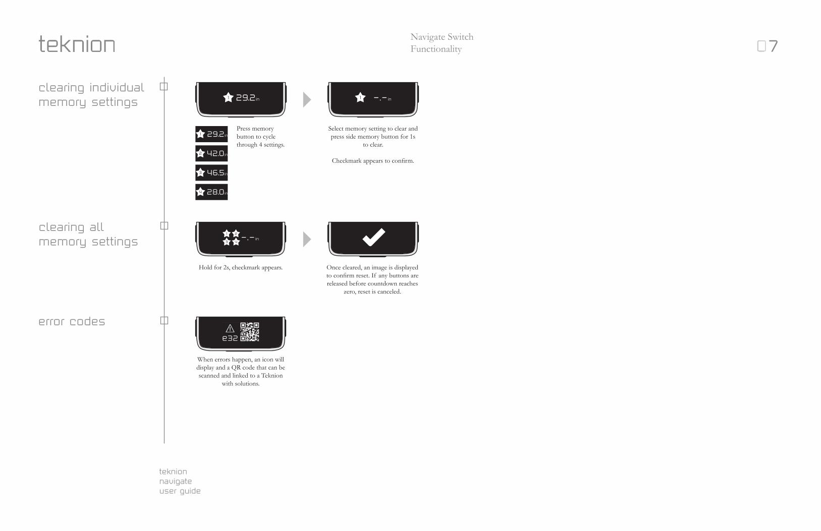
Press memory button to cycle through 4 settings.
Hold for 2s, checkmark appears.
When errors happen, an icon will display and a QR code that can be scanned and linked to a Teknion
with solutions.
Once cleared, an image is displayed to confirm reset. If any buttons are released before countdown reaches
zero, reset is canceled.
Select memory setting to clear and press side memory button for 1s
to clear.
Checkmark appears to confirm.
clearing individual memory settings
clearing all memory settings
error codes
1 29.2in 1
1 29.2in
2 42.0in
3 46.5in
4 28.0in
43
21
!
e32
Navigate SwitchFunctionality 0

teknion navigateuser guide
8Navigate SwitchFunctionality
When table needs to be initialized, the screen will flash with an arrow indicating to move the table down.
Press and hold Bluetooth and memory button for 5s to enter
factory reset mode.
Press and hold reminder and memory buttons for 2s to enter
Units/Offset change mode.
Press bluetooth button to confirm unit selection.
Flashing units (orange) indicate which units are modifiable.
In this image, the units can be changed between inches and
centimeters by pressing the side buttons.
Numbers will automatically update between centimeters and Inches.
Number readout will now flash to be changed. Confirm if desk height matches readout on display. If not,
press the paddle UP/DOWN to adjust readout dimension. Press and hold to
cycle through faster.
Once confirmed, press Bluetooth button and exit menu.
Display will show a countdown timer at 5s then that memory
setting will be cleared.
Once cleared, a image is displayed to confirm reset. If any buttons are released before countdown reaches zero, reset is canceled.
When table reaches the lowest setting and table initializes itself,
the check mark will appear and the table returns to normal use.
initialize
factory reset
units/offset mode
! !
46.5in
75cmcm
75cm
75
5
46.5in
0
teknion navigateuser guide
9
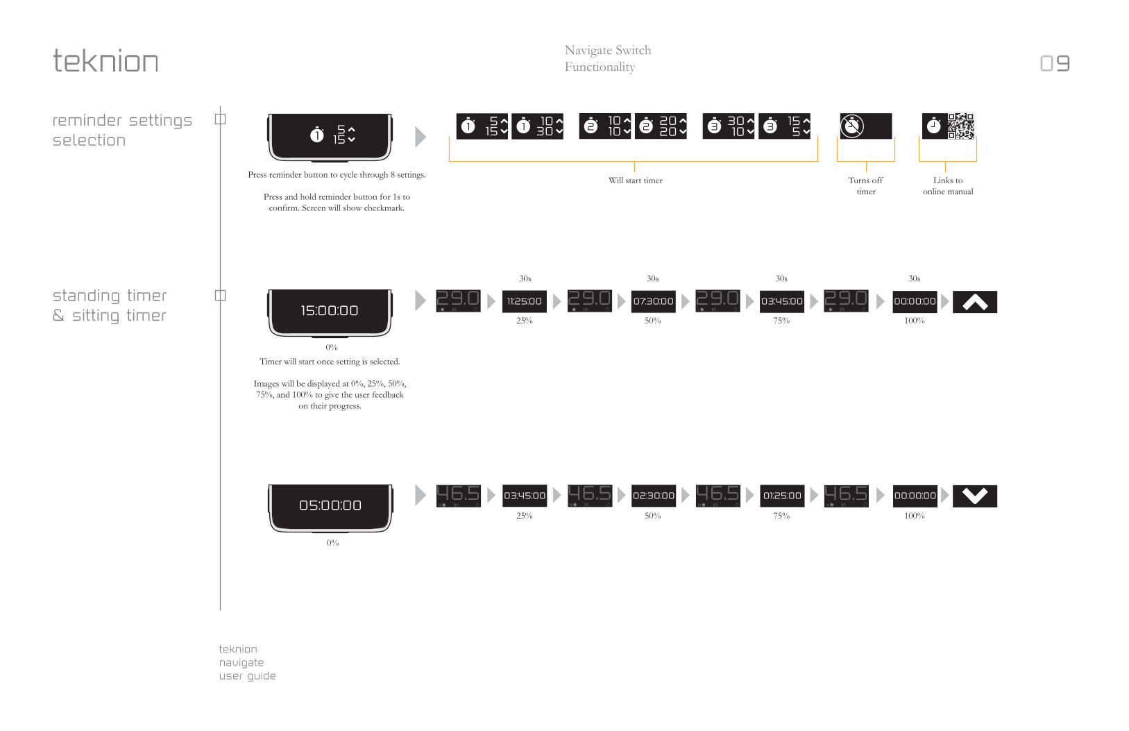
Press reminder button to cycle through 8 settings.
Press and hold reminder button for 1s to confirm. Screen will show checkmark.
Navigate SwitchFunctionality
reminder settings selection
standing timer & sitting timer
5151
515
1030
Will start timer Turns off timer
Links to online manual
Timer will start once setting is selected.
Images will be displayed at 0%, 25%, 50%, 75%, and 100% to give the user feedback
on their progress.
30s
25%
25%
50%
50%
75%
75%
100%
100%
30s 30s 30s
0%
0%
29.0 29.0 29.0 29.0
46.5 46.5 46.5 46.5
11:25:00
03:45:00 02:30:00 01:25:00 00:00:00
07:30:00 03:45:00 00:00:0015:00:00
05:00:00 in4 in4 in4 in4
1 in1 in1 in1 in
0
teknion navigateuser guide
10
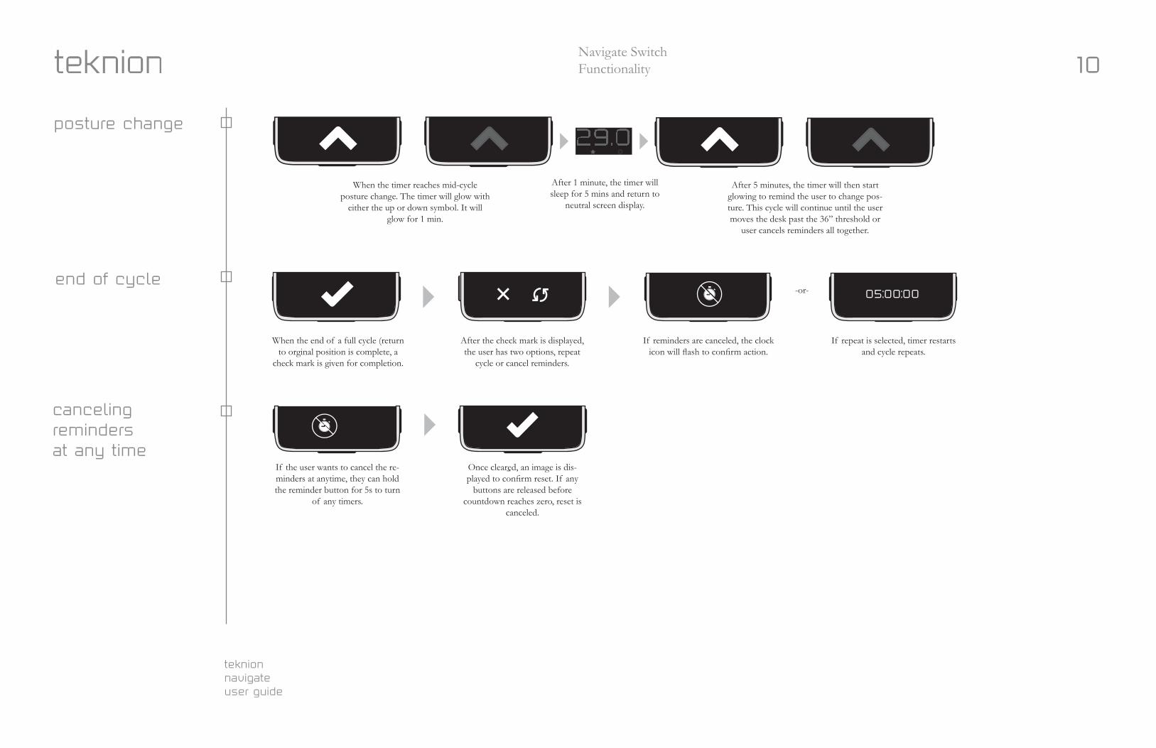
When the timer reaches mid-cycle posture change. The timer will glow with
either the up or down symbol. It will glow for 1 min.
When the end of a full cycle (return to orginal position is complete, a
check mark is given for completion.
After the check mark is displayed, the user has two options, repeat
cycle or cancel reminders.
If reminders are canceled, the clock icon will flash to confirm action.
If repeat is selected, timer restarts and cycle repeats.
After 5 minutes, the timer will then start glowing to remind the user to change pos-ture. This cycle will continue until the user moves the desk past the 36” threshold or
user cancels reminders all together.
After 1 minute, the timer will sleep for 5 mins and return to
neutral screen display.
-or-
posture change
end of cycle
in1
If the user wants to cancel the re-minders at anytime, they can hold the reminder button for 5s to turn
of any timers.
Once cleared, an image is dis-played to confirm reset. If any
buttons are released before countdown reaches zero, reset is
canceled.
canceling reminders at any time
Navigate SwitchFunctionality
05:00:00
teknion navigateuser guide
11
Reminder Settings
30/10 15/5 20/20 10/10
start timer
25% complete
75% complete50% complete
100% complete
sleep (5 mins)Move Desk
Move Desk Sleep (5 mins)
Repeat Cycle
Timer Off
Cycle Complete
Up/Down
Impulse Drive
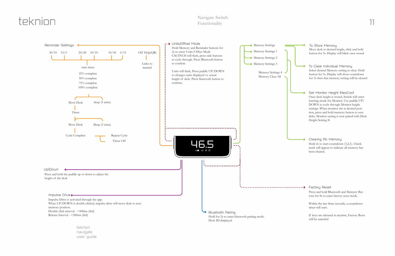
Bluetooth PairingHold for 2s to enter bluetooth pairing mode. Desk ID displayed.
Press and hold the paddle up or down to adjust the height of the desk
Impulse Drive is activated through the app.When UP/DOWN is double clicked, impulse drive will move desk to next memory position. Double click interval - <500ms (tbd)Release Interval - <300ms (tbd)
Timer
10/30 5/15 Off Help(QR)
Units/Offset Mode Memory Settings To Store MemoryMove desk to desired height, click and hold button for 2s. Display will blink once stored
Select desired Memory setting to clear. Hold button for 5s. Display will show countdown for 3s then that memory setting will be cleared
Once desk height is stored, Switch will enter learning mode for Monitor. Use paddle UP/DOWN to cycle through Monitor height settings. When monitor sits at desired posi-tion, press and hold memory button to save delta. Monitor setting is now paired with Desk Height Setting #.
Hold 2s to start countdown (3,2,1). Check-mark will appear to indicate all memory has been cleared.
Press and hold Bluetooth and Memory But-tons for 8s to enter factory reset mode.
Within the last three seconds, a countdown timer will start.
If keys are released at anytime, Factory Reset will be canceled
To Clear Individual Memory
Set Monitor Height (NeoCon)
Clearing All Memory
Factory Reset
Memory Settings 2
Memory Settings 4
Memory Settings 1
Memory Settings 3
Memory Clear All
Hold Memory and Reminder buttons for 2s to enter Units/Offset ModeCM/INCH will flash, press side buttons to cycle through. Press Bluetooth button to confirm
Units will flash, Press paddle UP/DOWN to changes units displayed vs. actual height of desk. Press bluetooth button to confirm.
Links tomanual
Navigate SwitchFunctionality
teknion navigateuser guide
12
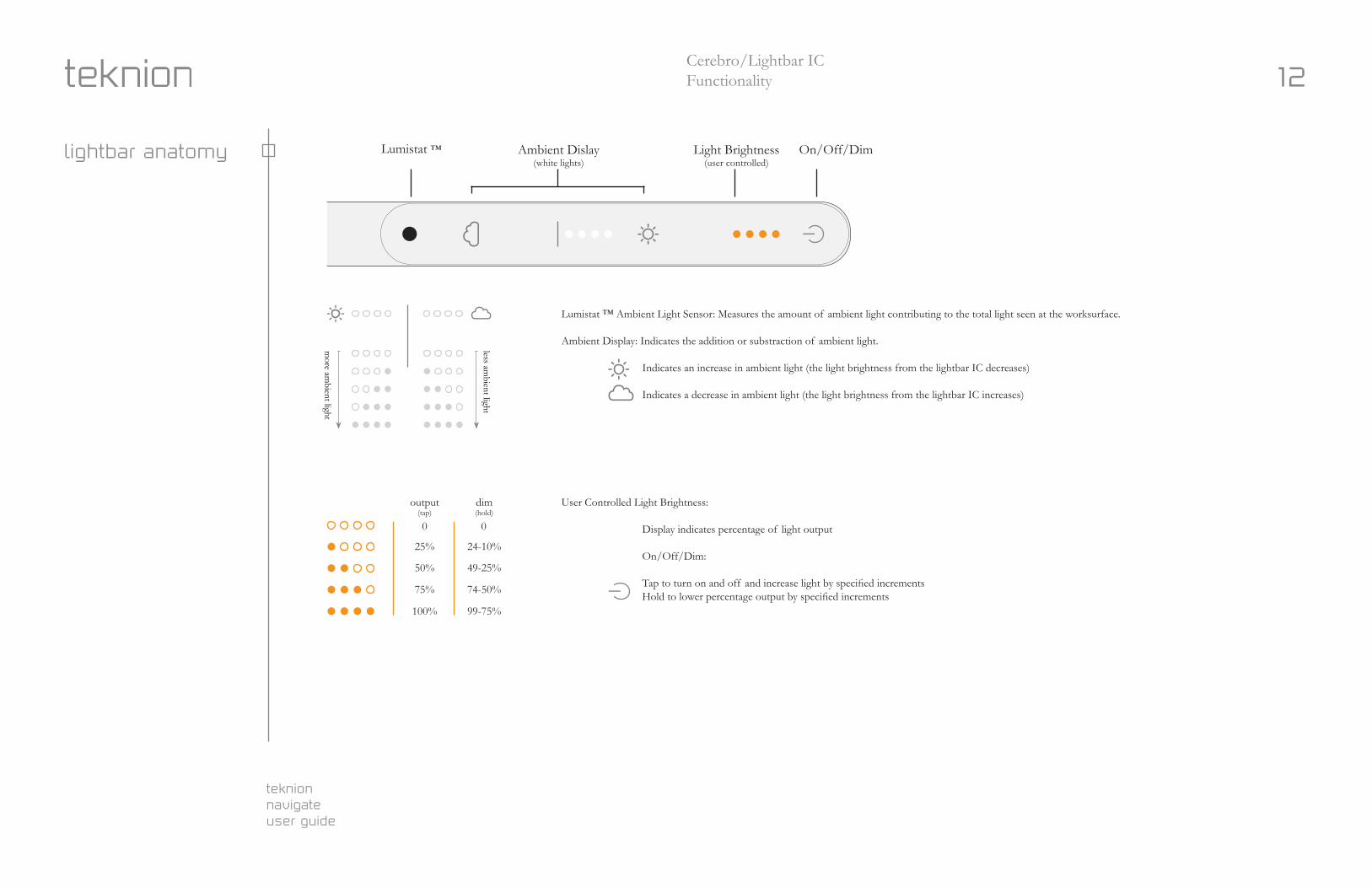
User Controlled Light Brightness:
Display indicates percentage of light output On/Off/Dim:
Tap to turn on and off and increase light by specified increments Hold to lower percentage output by specified increments
Cerebro/Lightbar ICFunctionality
lightbar anatomy Lumistat ™ Ambient Dislay(white lights)
Light Brightness(user controlled)
On/Off/Dim
output(tap)
25%
0 0
24-10%
50% 49-25%
75% 74-50%
100% 99-75%
dim(hold)
less ambient light
more am
bient light
Lumistat ™ Ambient Light Sensor: Measures the amount of ambient light contributing to the total light seen at the worksurface.
Ambient Display: Indicates the addition or substraction of ambient light.
Indicates an increase in ambient light (the light brightness from the lightbar IC decreases) Indicates a decrease in ambient light (the light brightness from the lightbar IC increases)
teknion navigateuser guide
13Cerebro/Lightbar ICFunctionality
cerebro / lightbar ic logic
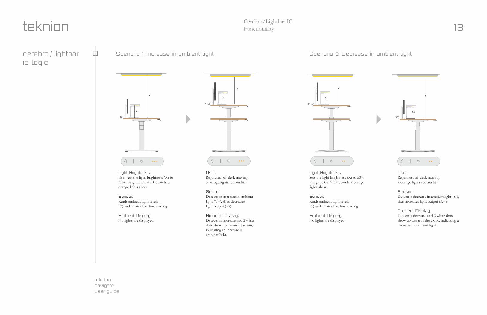
Light Brightness: User sets the light brightness (X) to 75% using the On/Off Switch. 3 orange lights show.
Sensor: Reads ambient light levels (Y) and creates baseline reading.
Ambient Display: No lights are displayed.
User: Regardless of desk moving, 3 orange lights remain lit.
Sensor: Detects an increase in ambient light (Y+), thus decreases light output (X-).
Ambient Display: Detects an increase and 2 white dots show up towards the sun, indicating an increase in ambient light.
Light Brightness: Sets the light brightness (X) to 50% using the On/Off Switch. 2 orange lights show.
Sensor: Reads ambient light levels (Y) and creates baseline reading.
Ambient Display: No lights are displayed.
User: Regardless of desk moving, 2 orange lights remain lit.
Sensor: Detects a decrease in ambient light (Y-), thus increases light output (X+).
Ambient Display: Detects a decrease and 2 white dotsshow up towards the cloud, indicating a decrease in ambient light.
Scenario #1: Increase in Ambient Light
29”
41.5”
X
YX -
Y+
Light Brightness: Sets the light brightness (X) to 75% using the On/Off Switch. 3 orange lights show
Sensor: Reads ambient light levels (Y) and creates baseline reading.
Ambient Display: No lights are displayed.
User: Regardless of desk moving, 3 orange lights remain lit.
Sensor: Detects a increase in ambient light (Y+), thus decreas-es light output (X-)
Ambient Display: Detects an increase and 2 white dots show up towards the sun, indicating an increase in ambient light
Notes:
Light Brightness display (orange lights) not linked to Ambient Display. It will never change when light adjusts automatically.
Ambient Display Sensitivity: 30/60/90/300/600 (tbd from testing)
Scenario #2: Decrease in Ambient Light
29”
41.5”
X+
Y-X
Y
Light Brightness: Sets the light brightness (X) to 50% using the On/Off Switch. 2 orange lights show.
Sensor: Reads ambient light levels (Y) and creates baseline reading.
Ambient Display: No lights are displayed
User: Regardless of desk moving, 2 orange lights remain lit.
Sensor: Detects a decrease in ambient light (Y-), thus increases light output (X+)
Ambient Display: Detects a decrease and 1 white dots show up towards the cloud, indicating a decrease in ambient light
Light Sensor
Ambient Display (White lights)
Light Brightness (Orange lights)
On/Off Hold to dim
Scenario 1: Increase in ambient light Scenario 2: Decrease in ambient light
norco
used bikes
teknion navigateuser guide
14Cerebro/Lightbar ICFunctionality
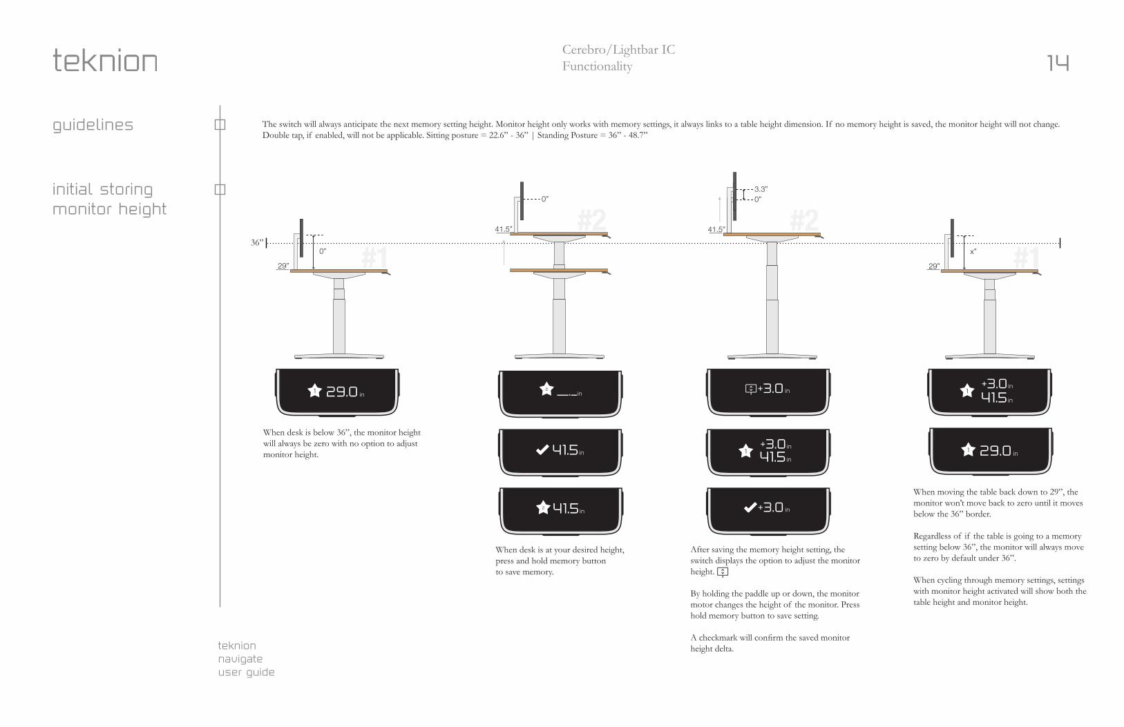
guidelines The switch will always anticipate the next memory setting height. Monitor height only works with memory settings, it always links to a table height dimension. If no memory height is saved, the monitor height will not change.Double tap, if enabled, will not be applicable. Sitting posture = 22.6” - 36” | Standing Posture = 36” - 48.7”
initial storingmonitor height
| Cerebro Switch Functionality
29”
0”
0” 0”3.3”
41.5”
Hold 1s Hold 1s
1 29.0in
1 29.0in
2 __._in
41.5in
2 41.5in
When desk is below 36”, the Monitor Height will always be zero.
When saving memory, you will not be allowed to adjust monitor height, it will skip this step
Switch will always anticipate the next memory setting height. If no memory height is selected, the monitor height will not change unless crossing the 36” border.
Monitor height only works with memory settings, it always links to a table height dimension.
05.16.2018
When the desk is at your desired height, press and hold side button to save memory like normal
Screen displays Monitor height adjusting. By holding the paddle up or down, the monitor motor changes height.
When moving the table back down to 29”, the monitor won’t move back to zero until it moves below the 36” border since there is no other memory settings set.
Regardless of if the table is going to a memory setting below 36”, the monitor will always move to zero by default under this dimension.
When cycling through memory settings, settings with Monitor Height activated will show both the table height and monitor height
Display 1s
Sit/Stand border is 36”:22.5-36” = Sitting posture36”-48” = Standing postureGuidelines
Initial Storing Monitor Height
29”
x”
41.5”#2 #2#1 #1
+3.0inDisplay 1s
>36” won’t showMonitor Height
+3.0in
Hold 1s
1+3.0
in41.5in
1+3.0
in41.5in
1in+3.0
in+3.0
When desk is below 36”, the monitor height will always be zero with no option to adjust monitor height.
When desk is at your desired height, press and hold memory button to save memory.
After saving the memory height setting, the switch displays the option to adjust the monitor height.
By holding the paddle up or down, the monitor motor changes the height of the monitor. Press hold memory button to save setting.
A checkmark will confirm the saved monitor height delta.
When moving the table back down to 29”, the monitor won’t move back to zero until it moves below the 36” border.
Regardless of if the table is going to a memory setting below 36”, the monitor will always move to zero by default under 36”.
When cycling through memory settings, settings with monitor height activated will show both the table height and monitor height.
+3.01
in29.0
+3.01
in29.0
12
+3.02in41.5
1in+3.0in41.5
in41.5
+3.0in41.5
in+3.0
36”
teknion navigateuser guide
15Cerebro/Lightbar ICFunctionality
moving to stored memory setting
| Cerebro Switch Functionality 05.16.2018
29”
0”
41.5”
36”
When moving the desk back to the saved position #2 (41.5” +3.0”):
Switch will reference the next memory setting (in this case #2) and start moving the monitor after the 36” border.
This is to ensure that when the table reaches the 41.5” height, that the monitor is working towards it’s 3.0” setting.
If no memory setting above 36”, monitor won’t move from zero position
When moving the desk from one standing height memory setting #1 (41.5” +3.0”) to another memory setting higher #2 (47” +5.0”):
Switch will reference the next memory setting and start moving the monitor right away
This is to ensure that when the table reaches 47”, that the monitor is working towards it’s 5.0” setting.
When moving the desk to return to the original standing height setting (41.5” + 3.0”):
Switch will reference the next memory setting and start moving the monitor right away
This is to ensure that when the table reaches the 41.5” height, that the monitor is working towards it’s 3.0” setting.
If no memory setting is set above or below the standing height, the monitor will remain in that position (unless desk is moved below 36”h)
0”
#2#1
#2#141.5”
0”3.0”3.0”
41.5”
47.0”
0”
5.0”
Moving to Stored Memory Setting Moving between 2 stored memory settings
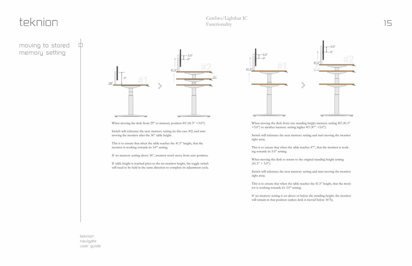
When moving the desk from 29” to memory position #2 (41.5” +3.0”): Switch will reference the next memory setting (in this case #2) and start moving the monitor after the 36” table height.
This is to ensure that when the table reaches the 41.5” height, that the monitor is working towards its 3.0” setting.
If no memory setting above 36”, monitor won’t move from zero position.
If table height is reached prior to the set monitor height, the toggle switch will need to be held in the same direction to complete its adjustment cycle.
When moving the desk from one standing height memory setting #2 (41.5” +3.0”) to another memory setting higher #3 (47” +5.0”):
Switch will reference the next memory setting and start moving the monitor right away.
This is to ensure that when the table reaches 47”, that the monitor is work-ing towards its 5.0” setting.
When moving the desk to return to the original standing height setting (41.5” + 3.0”):
Switch will reference the next memory setting and start moving the monitor right away.
This is to ensure that when the table reaches the 41.5” height, that the moni-tor is working towards it’s 3.0” setting.
If no memory setting is set above or below the standing height, the monitor will remain in that position (unless desk is moved below 36”h).
teknion navigateuser guide
16Cerebro/Lightbar ICFunctionality
swtich release before memory setting
| Cerebro Switch Functionality 05.16.2018
If switch is released inbetween #1 and #2:
Desk will stop at the released height.
Monitor will freeze position.
If switch is pressed to continue, the monitor will continue moving in the original direction until height is reached.
If switch is pressed to reverse direction, the monitor will return to it’s original height prior to moving the switch.
#2#141.5”
0”3.0”
41.5”
47.0”
0”
5.0”
Switch is released before reaching memory setting
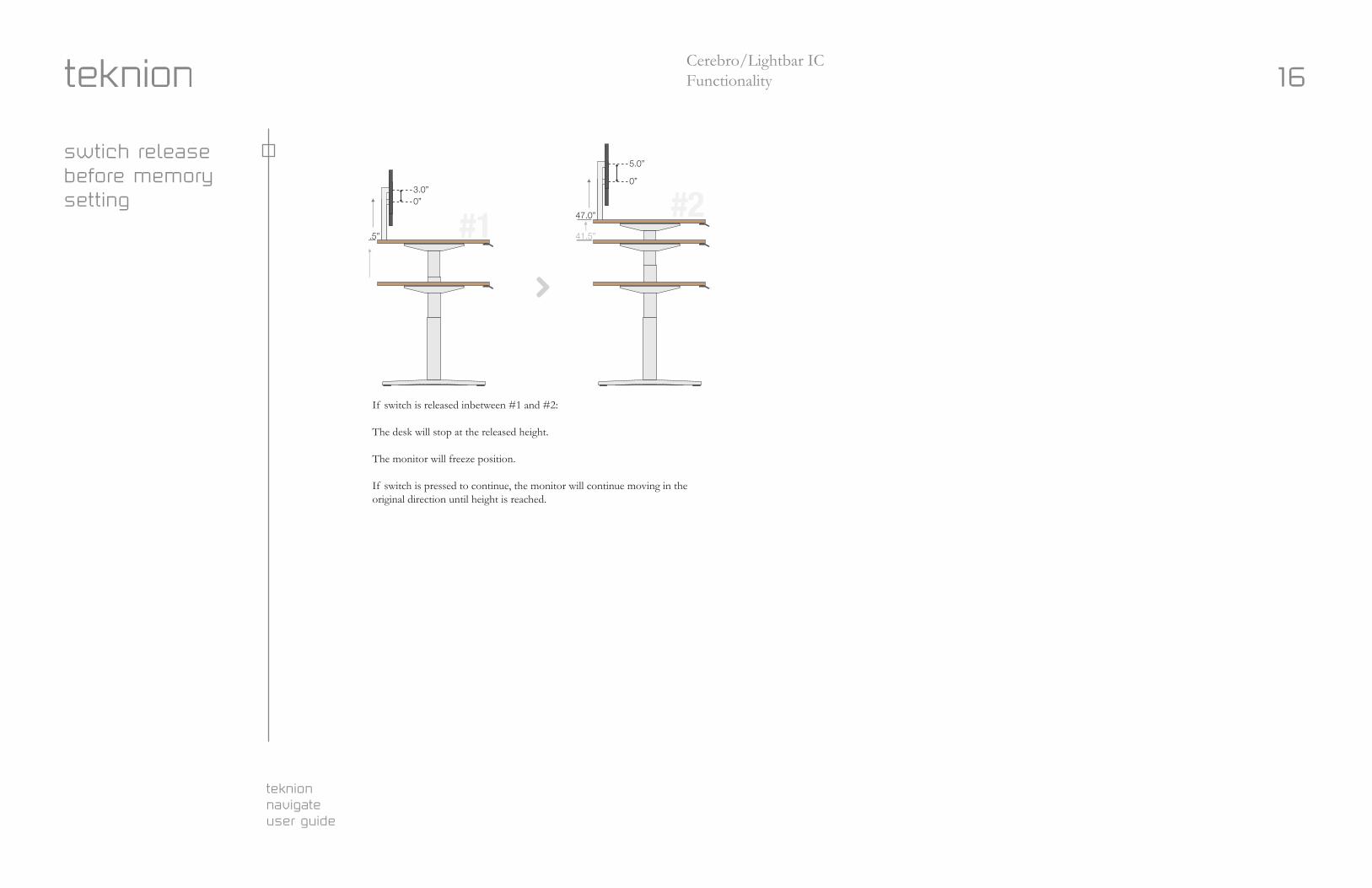
If switch is released inbetween #1 and #2:
The desk will stop at the released height.
The monitor will freeze position.
If switch is pressed to continue, the monitor will continue moving in the original direction until height is reached.
teknion navigateuser guide
17Error Codes
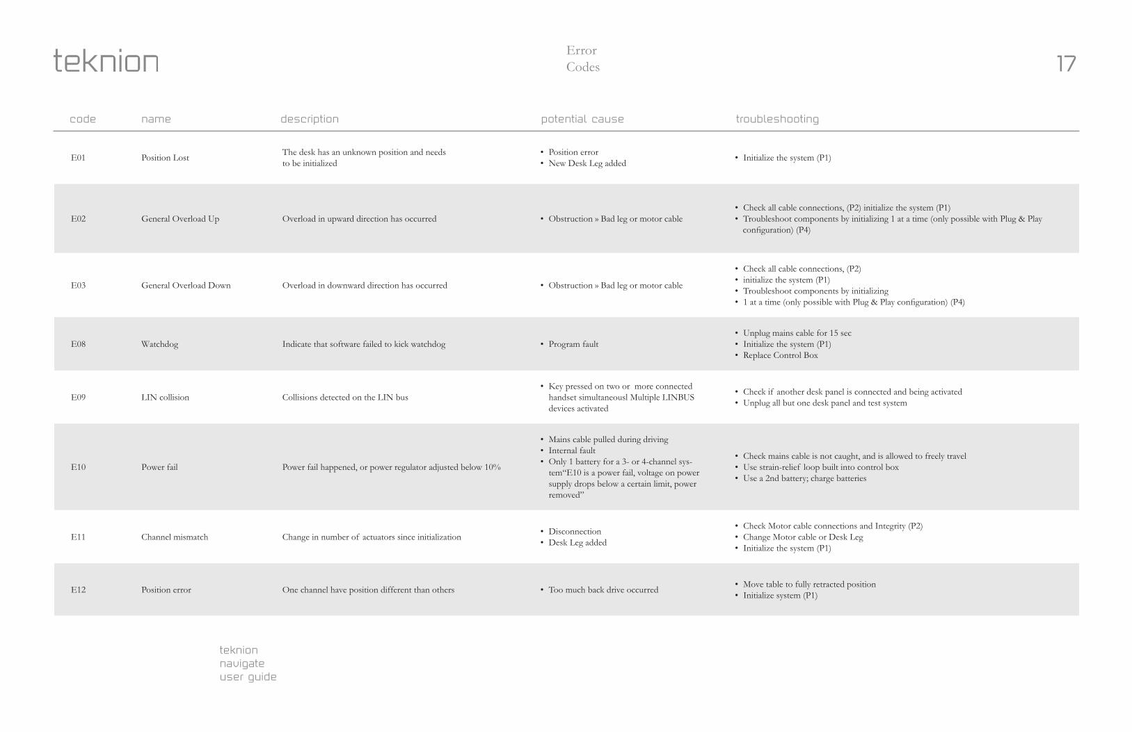
E01 Position Lost The desk has an unknown position and needsto be initialized
• Position error• New Desk Leg added • Initialize the system (P1)
E02 General Overload Up Overload in upward direction has occurred • Obstruction » Bad leg or motor cable• Check all cable connections, (P2) initialize the system (P1) • Troubleshoot components by initializing 1 at a time (only possible with Plug & Play
configuration) (P4)
E03 General Overload Down Overload in downward direction has occurred • Obstruction » Bad leg or motor cable
• Check all cable connections, (P2) • initialize the system (P1) • Troubleshoot components by initializing• 1 at a time (only possible with Plug & Play configuration) (P4)
E08 Watchdog Indicate that software failed to kick watchdog • Program fault• Unplug mains cable for 15 sec• Initialize the system (P1)• Replace Control Box
E09 LIN collision Collisions detected on the LIN bus• Key pressed on two or more connected
handset simultaneousl Multiple LINBUS devices activated
• Check if another desk panel is connected and being activated• Unplug all but one desk panel and test system
E10 Power fail Power fail happened, or power regulator adjusted below 10%
• Mains cable pulled during driving• Internal fault• Only 1 battery for a 3- or 4-channel sys-
tem“E10 is a power fail, voltage on power supply drops below a certain limit, power removed”
• Check mains cable is not caught, and is allowed to freely travel• Use strain-relief loop built into control box • Use a 2nd battery; charge batteries
E11 Channel mismatch Change in number of actuators since initialization • Disconnection• Desk Leg added
• Check Motor cable connections and Integrity (P2)• Change Motor cable or Desk Leg• Initialize the system (P1)
E12 Position error One channel have position different than others • Too much back drive occurred • Move table to fully retracted position• Initialize system (P1)
code name description potential cause troubleshooting
teknion navigateuser guide
18Error Codes
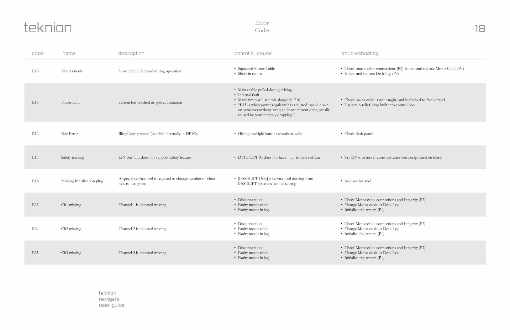
E13 Short circuit Short circuit detected during operation • Squeezed Motor Cable• Short in motor
• Check motor cable connections (P2) Isolate and replace Motor Cable (P4) • Isolate and replace Desk Leg (P4)
E15 Power limit System has reached its power limitation
• Mains cable pulled during driving• Internal fault• Many times will see this alongside E10• “E15 is when power regulator has adjusted speed down
on actuators without any significant current draw, usually caused by power supply dropping.”
• Check mains cable is not caught, and is allowed to freely travel• Use strain-relief loop built into control box
E16 Key Error Illegal keys pressed (handled internally in DP1C). • Hitting multiple buttons simultaneously • Check desk panel
E17 Safety missing LIN bus unit does not support safety feature • DP1C/DPF1C does not have up-to-date softwar • Try DP with more recent software version (printed on label)
E18 Missing Initialization plug A special service tool is required to change number of chan-nels to the system
• [BASELIFT Only] » Service tool missing from BASELIFT system when initializing • Add service tool
E23 Ch1 missing Channel 1 is detected missing• Disconnection• Faulty motor cable• Faulty motor in leg
• Check Motor cable connections and Integrity (P2)• Change Motor cable or Desk Leg• Initialize the system (P1)
E24 Ch2 missing Channel 2 is detected missing• Disconnection• Faulty motor cable• Faulty motor in leg
• Check Motor cable connections and Integrity (P2)• Change Motor cable or Desk Leg• Initialize the system (P1)
E25 Ch3 missing Channel 3 is detected missing• Disconnection• Faulty motor cable• Faulty motor in leg
• Check Motor cable connections and Integrity (P2)• Change Motor cable or Desk Leg• Initialize the system (P1)
code name description potential cause troubleshooting
teknion navigateuser guide
19Error Codes
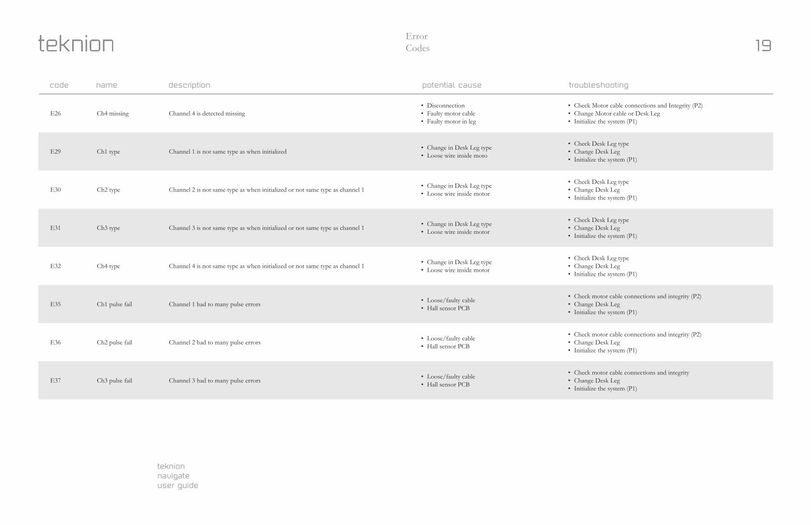
E26 Ch4 missing Channel 4 is detected missing• Disconnection• Faulty motor cable• Faulty motor in leg
• Check Motor cable connections and Integrity (P2)• Change Motor cable or Desk Leg• Initialize the system (P1)
E29 Ch1 type Channel 1 is not same type as when initialized • Change in Desk Leg type• Loose wire inside moto
• Check Desk Leg type • Change Desk Leg• Initialize the system (P1)
E30 Ch2 type Channel 2 is not same type as when initialized or not same type as channel 1 • Change in Desk Leg type• Loose wire inside motor
• Check Desk Leg type• Change Desk Leg• Initialize the system (P1)
E31 Ch3 type Channel 3 is not same type as when initialized or not same type as channel 1 • Change in Desk Leg type• Loose wire inside motor
• Check Desk Leg type• Change Desk Leg• Initialize the system (P1)
E32 Ch4 type Channel 4 is not same type as when initialized or not same type as channel 1 • Change in Desk Leg type• Loose wire inside motor
• Check Desk Leg type• Change Desk Leg• Initialize the system (P1)
E35 Ch1 pulse fail Channel 1 had to many pulse errors • Loose/faulty cable• Hall sensor PCB
• Check motor cable connections and integrity (P2)• Change Desk Leg• Initialize the system (P1)
E36 Ch2 pulse fail Channel 2 had to many pulse errors • Loose/faulty cable• Hall sensor PCB
• Check motor cable connections and integrity (P2)• Change Desk Leg• Initialize the system (P1)
E37 Ch3 pulse fail Channel 3 had to many pulse errors • Loose/faulty cable• Hall sensor PCB
• Check motor cable connections and integrity• Change Desk Leg• Initialize the system (P1)
code name description potential cause troubleshooting
teknion navigateuser guide
20Error Codes
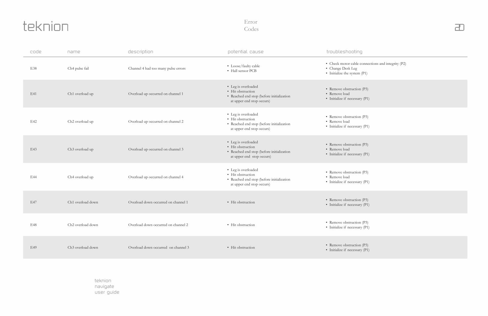
E38 Ch4 pulse fail Channel 4 had too many pulse errors • Loose/faulty cable• Hall sensor PCB
• Check motor cable connections and integrity (P2)• Change Desk Leg• Initialize the system (P1)
E41 Ch1 overload up Overload up occurred on channel 1
• Leg is overloaded• Hit obstruction• Reached end stop (before initialization
at upper end stop occurs)
• Remove obstruction (P3)• Remove load• Initialize if necessary (P1)
E42 Ch2 overload up Overload up occurred on channel 2
• Leg is overloaded• Hit obstruction• Reached end stop (before initialization
at upper end stop occurs)
• Remove obstruction (P3)• Remove load• Initialize if necessary (P1)
E43 Ch3 overload up Overload up occurred on channel 3
• Leg is overloaded• Hit obstruction• Reached end stop (before initialization
at upper end stop occurs)
• Remove obstruction (P3)• Remove load• Initialize if necessary (P1)
E44 Ch4 overload up Overload up occurred on channel 4
• Leg is overloaded• Hit obstruction• Reached end stop (before initialization
at upper end stop occurs)
• Remove obstruction (P3)• Remove load• Initialize if necessary (P1)
E47 Ch1 overload down Overload down occurred on channel 1 • Hit obstruction • Remove obstruction (P3)• Initialize if necessary (P1)
E48 Ch2 overload down Overload down occurred on channel 2 • Hit obstruction • Remove obstruction (P3)• Initialize if necessary (P1)
E49 Ch3 overload down Overload down occurred on channel 3 • Hit obstruction • Remove obstruction (P3)• Initialize if necessary (P1)
code name description potential cause troubleshooting
teknion navigateuser guide
21Error Codes
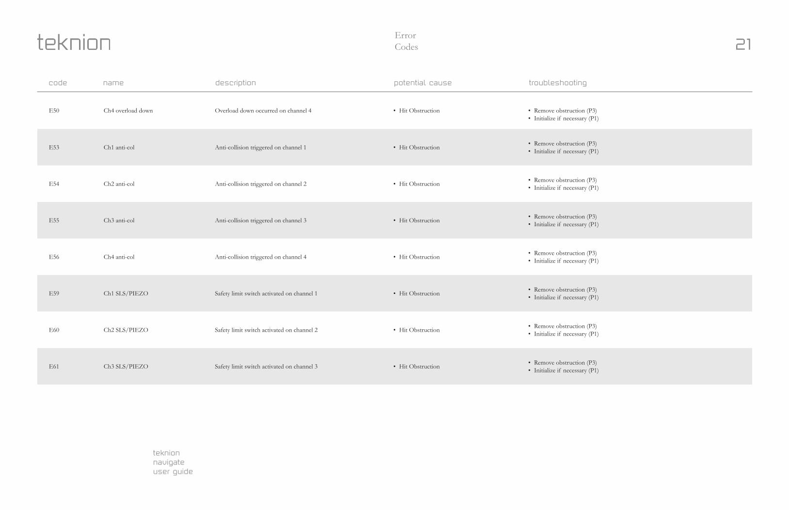
E50 Ch4 overload down Overload down occurred on channel 4 • Hit Obstruction • Remove obstruction (P3)• Initialize if necessary (P1)
E53 Ch1 anti-col Anti-collision triggered on channel 1 • Hit Obstruction • Remove obstruction (P3)• Initialize if necessary (P1)
E54 Ch2 anti-col Anti-collision triggered on channel 2 • Hit Obstruction • Remove obstruction (P3)• Initialize if necessary (P1)
E55 Ch3 anti-col Anti-collision triggered on channel 3 • Hit Obstruction • Remove obstruction (P3)• Initialize if necessary (P1)
E56 Ch4 anti-col Anti-collision triggered on channel 4 • Hit Obstruction • Remove obstruction (P3)• Initialize if necessary (P1)
E59 Ch1 SLS/PIEZO Safety limit switch activated on channel 1 • Hit Obstruction • Remove obstruction (P3)• Initialize if necessary (P1)
E60 Ch2 SLS/PIEZO Safety limit switch activated on channel 2 • Hit Obstruction • Remove obstruction (P3)• Initialize if necessary (P1)
E61 Ch3 SLS/PIEZO Safety limit switch activated on channel 3 • Hit Obstruction • Remove obstruction (P3)• Initialize if necessary (P1)
code name description potential cause troubleshooting
teknion navigateuser guide
22Error Codes
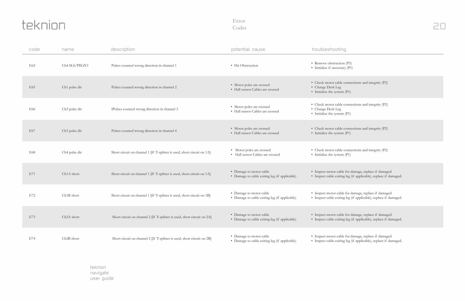
E62 Ch4 SLS/PIEZO Pulses counted wrong direction in channel 1 • Hit Obstruction • Remove obstruction (P3)• Initialize if necessary (P1)
E65 Ch1 pulse dir Pulses counted wrong direction in channel 2 • Motor poles are crossed• Hall sensor Cables are crossed
• Check motor cable connections and integrity (P2)• Change Desk Leg• Initialize the system (P1)
E66 Ch2 pulse dir IPulses counted wrong direction in channel 3 • Motor poles are crossed• Hall sensor Cables are crossed
• Check motor cable connections and integrity (P2)• Change Desk Leg• Initialize the system (P1)
E67 Ch3 pulse dir Pulses counted wrong direction in channel 4 • Motor poles are crossed• Hall sensor Cables are crossed
• Check motor cable connections and integrity (P2)• Initialize the system (P1)
E68 Ch4 pulse dir Short circuit on channel 1 [If T-splitter is used, short circuit on 1A] • Motor poles are crossed• Hall sensor Cables are crossed
• Check motor cable connections and integrity (P2)• Initialize the system (P1)
E71 Ch1A short Short circuit on channel 1 [If T-splitter is used, short circuit on 1A] • Damage to motor cable• Damage to cable exiting leg (if applicable)
• Inspect motor cable for damage, replace if damaged• Inspect cable exiting leg (if applicable), replace if damaged.
E72 Ch1B short Short circuit on channel 1 [If T-splitter is used, short circuit on 1B] • Damage to motor cable• Damage to cable exiting leg (if applicable)
• Inspect motor cable for damage, replace if damaged• Inspect cable exiting leg (if applicable), replace if damaged.
E73 Ch2A short Short circuit on channel 2 [If T-splitter is used, short circuit on 2A] • Damage to motor cable• Damage to cable exiting leg (if applicable)
• Inspect motor cable for damage, replace if damaged• Inspect cable exiting leg (if applicable), replace if damaged.
E74 Ch2B short Short circuit on channel 2 [If T-splitter is used, short circuit on 2B] • Damage to motor cable• Damage to cable exiting leg (if applicable)
• Inspect motor cable for damage, replace if damaged• Inspect cable exiting leg (if applicable), replace if damaged.
code name description potential cause troubleshooting
20