naval hydro pack: overview of numerics and...
TRANSCRIPT

Naval Hydro Pack: Overview of Numericsand Capability
Hrvoje Jasak
Wikki Ltd, UK and FSB Uni Zagreb, [email protected], [email protected]
OceanFOAM Conference, Danish Technical University
Copenhagen, 20 January 2015
Naval Hydro Pack: Overview of Numerics and Capability – p. 1

Outline
Objective
• Describe main details and improvements in numerical treatment of the free surfaceflow system in the Naval Hydro pack
Topics
1. Free surface flow modelling using CFD: Review of Equations
2. Preserving sharp interface: VOF or Level Set?
3. Formulation of the momentum equation
4. Pressure and dynamic pressure
5. Preserving water level in hydrodynamic resistance simulations
6. Relaxation zones and boundaries
7. Examples of simulations with the Naval Hydro Pack• Basic transient simulations• Sloshing, slamming and water wave impact on structures
• Steady resistance simulations• Forced oscillation simulations• Sea-keeping simulations
8. Summary
Naval Hydro Pack: Overview of Numerics and Capability – p. 2
Free Surface Flows
Modelling of Free Surface Flows: Review of Equations
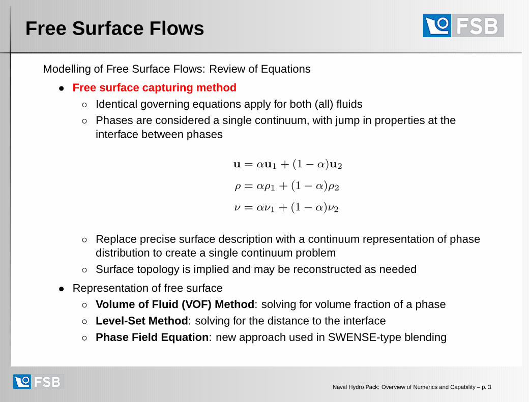
• Free surface capturing method◦ Identical governing equations apply for both (all) fluids
◦ Phases are considered a single continuum, with jump in properties at theinterface between phases
u = αu1 + (1− α)u2
ρ = αρ1 + (1− α)ρ2
ν = αν1 + (1− α)ν2
◦ Replace precise surface description with a continuum representation of phasedistribution to create a single continuum problem
◦ Surface topology is implied and may be reconstructed as needed
• Representation of free surface
◦ Volume of Fluid (VOF) Method : solving for volume fraction of a phase
◦ Level-Set Method : solving for the distance to the interface
◦ Phase Field Equation : new approach used in SWENSE-type blending
Naval Hydro Pack: Overview of Numerics and Capability – p. 3
VOF Free Surface Flow Model
Modelling of Free Surface Flows: Review of Equations
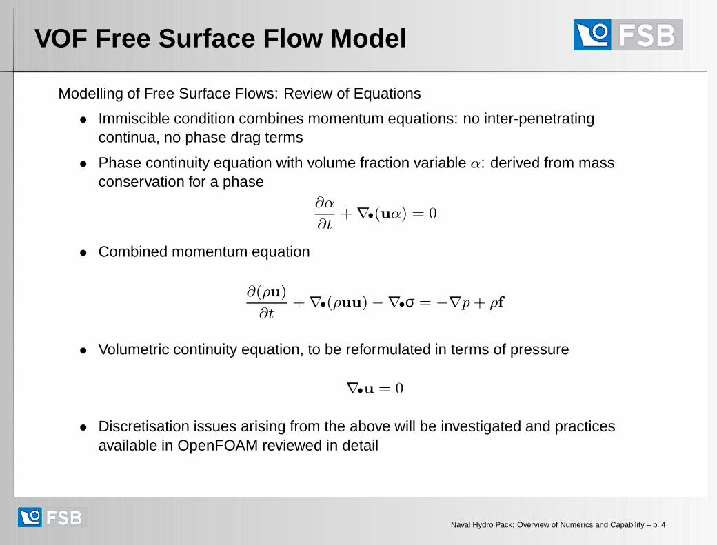
• Immiscible condition combines momentum equations: no inter-penetratingcontinua, no phase drag terms
• Phase continuity equation with volume fraction variable α: derived from massconservation for a phase
∂α
∂t+∇•(uα) = 0
• Combined momentum equation
∂(ρu)
∂t+∇•(ρuu)−∇•σ = −∇p+ ρf
• Volumetric continuity equation, to be reformulated in terms of pressure
∇•u = 0
• Discretisation issues arising from the above will be investigated and practicesavailable in OpenFOAM reviewed in detail
Naval Hydro Pack: Overview of Numerics and Capability – p. 4

VoF Equation Discretisation
Numerical Considerations: Preserving Sharp Interface with VOF
• Preserving sharpness of the free surface is paramount for the accuracy and qualityof the solution
• Boundedness of the α field must be preserved at all cost
◦ Violation of bounds, 0 ≤ α ≤ 1, may lead to negative viscosity or density, dueto
ρ = αρ1 + (1− α)ρ2
◦ Clipping the limits on α is unacceptable: phase conservation error
• Conventional numerics preserves boundedness by blending first order convection,which leads to loss of sharpness in interface
Alternative Formulations: Level Set Formulation
• Level set equation resolves the issue of boundedness, but fails on massconservation: this cannot be enforced!
• The biggest advantage: free surface smearing becomes a user-defined parameter
• Disadvantage: reinitialisation step is necessary!
• Phase field method: a new avenue of research; using a special (self-similar)signed distance function without the need to redistance
Naval Hydro Pack: Overview of Numerics and Capability – p. 5
VoF Equation Discretisation
Numerical Considerations: Preserving Sharp Interface
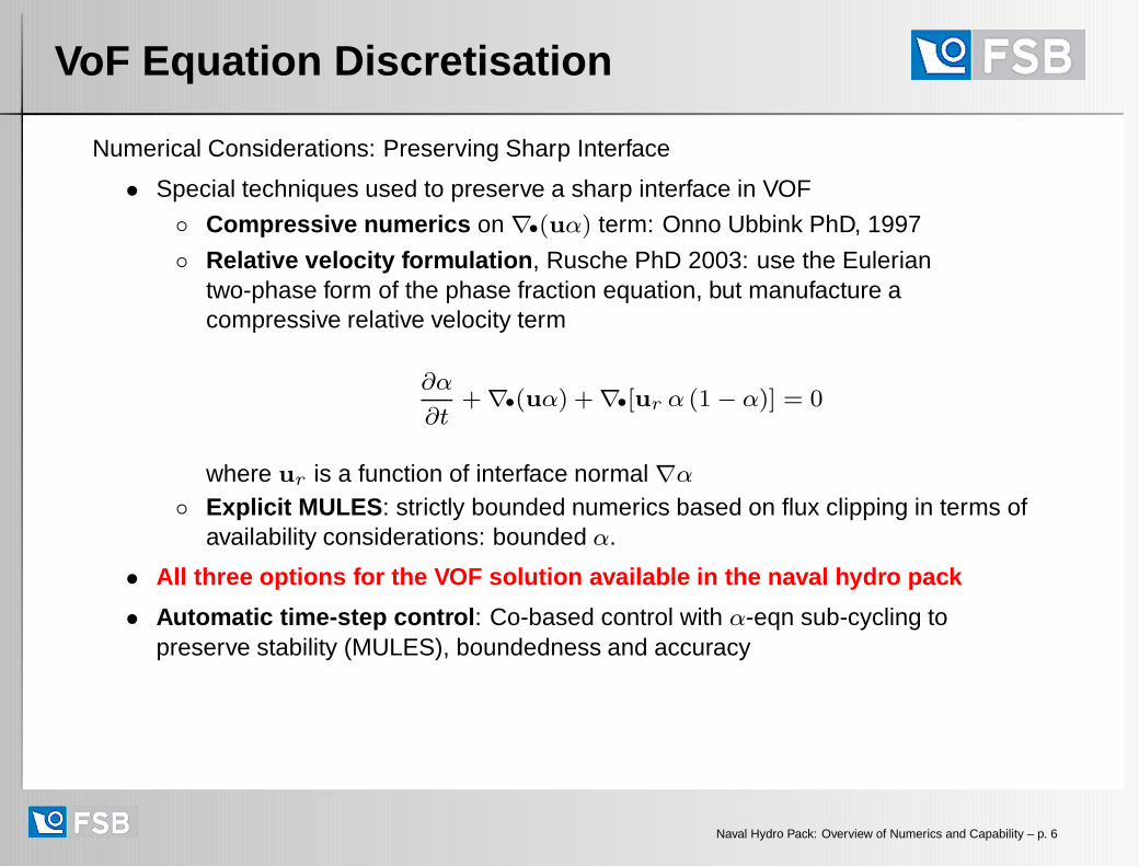
• Special techniques used to preserve a sharp interface in VOF
◦ Compressive numerics on ∇•(uα) term: Onno Ubbink PhD, 1997
◦ Relative velocity formulation , Rusche PhD 2003: use the Euleriantwo-phase form of the phase fraction equation, but manufacture acompressive relative velocity term
∂α
∂t+∇•(uα) +∇•[ur α (1− α)] = 0
where ur is a function of interface normal ∇α
◦ Explicit MULES : strictly bounded numerics based on flux clipping in terms ofavailability considerations: bounded α.
• All three options for the VOF solution available in the naval hydro pack
• Automatic time-step control : Co-based control with α-eqn sub-cycling topreserve stability (MULES), boundedness and accuracy
Naval Hydro Pack: Overview of Numerics and Capability – p. 6
VoF Equation Discretisation
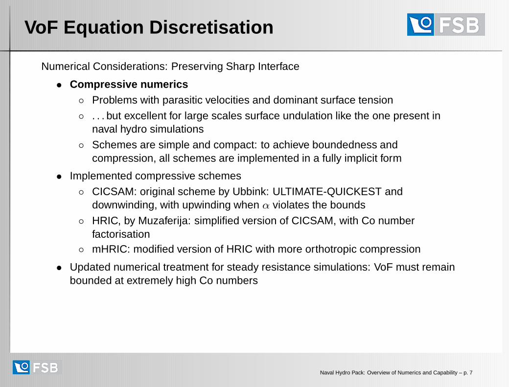
Numerical Considerations: Preserving Sharp Interface
• Compressive numerics◦ Problems with parasitic velocities and dominant surface tension
◦ . . . but excellent for large scales surface undulation like the one present innaval hydro simulations
◦ Schemes are simple and compact: to achieve boundedness andcompression, all schemes are implemented in a fully implicit form
• Implemented compressive schemes
◦ CICSAM: original scheme by Ubbink: ULTIMATE-QUICKEST anddownwinding, with upwinding when α violates the bounds
◦ HRIC, by Muzaferija: simplified version of CICSAM, with Co numberfactorisation
◦ mHRIC: modified version of HRIC with more orthotropic compression
• Updated numerical treatment for steady resistance simulations: VoF must remainbounded at extremely high Co numbers
Naval Hydro Pack: Overview of Numerics and Capability – p. 7
VoF Equation Discretisation
Numerical Considerations: Preserving Sharp Interface
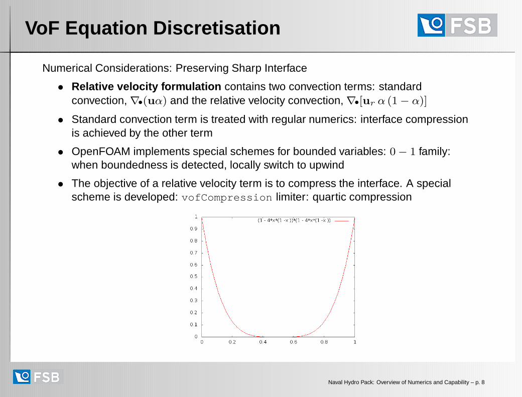
• Relative velocity formulation contains two convection terms: standardconvection, ∇•(uα) and the relative velocity convection, ∇•[ur α (1− α)]
• Standard convection term is treated with regular numerics: interface compressionis achieved by the other term
• OpenFOAM implements special schemes for bounded variables: 0− 1 family:when boundedness is detected, locally switch to upwind
• The objective of a relative velocity term is to compress the interface. A specialscheme is developed: vofCompression limiter: quartic compression
Naval Hydro Pack: Overview of Numerics and Capability – p. 8

VoF Equation Discretisation
Numerical Considerations: Preserving Sharp Interface
• Explicit MULES : resolving a boundedness problem based on availability criterion
PW E
N
S
• Due to the handling of boundedness condition and requirement for sharp interfaceresolution, both convection terms are considerably non-linear in a discretisedversion
• However, even minor unboundedness is problematic: need to achieve strictboundedness without clipping
Naval Hydro Pack: Overview of Numerics and Capability – p. 9

Momentum Equation Discretisation
Numerical Considerations: Formulation of the Momentum Equation
• In cells containing the interface, pathological cases exist where the receding waterlevel causes unphysical acceleration of light phase (air)
PW E
N
S
u
u
• This situation occurs regularly and acceleration is generated close to the interface:worst possible place!
Naval Hydro Pack: Overview of Numerics and Capability – p. 10
Momentum Equation Discretisation
Numerical Considerations: Formulation of the Momentum Equation
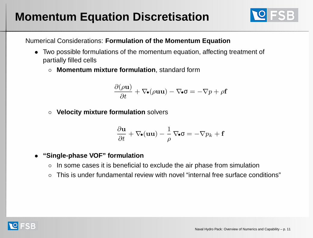
• Two possible formulations of the momentum equation, affecting treatment ofpartially filled cells
◦ Momentum mixture formulation , standard form
∂(ρu)
∂t+∇•(ρuu)−∇•σ = −∇p+ ρf
◦ Velocity mixture formulation solvers
∂u
∂t+∇•(uu)−
1
ρ∇•σ = −∇pk + f
• “Single-phase VOF” formulation◦ In some cases it is beneficial to exclude the air phase from simulation
◦ This is under fundamental review with novel “internal free surface conditions”
Naval Hydro Pack: Overview of Numerics and Capability – p. 11

VOF Free Surface Flow Model
Numerical Considerations: Pressure Handling
• Pressure field contains gravity contribution: hydrostatic pressure from ρf
• To ensure smooth numerics, buoyancy is removed from the momentum equationand built into the pressure. Decomposition implies
p = pd + ρ gh
• PIMPLE/SIMPLE p− u coupling in terms of dynamic pressure pd for bettercoupling and easier handling of pressure boundary conditions
• Simple definition is not appropriate on moving boundaries: “floating bodies sink”
• Naval hydro pack implements implicit reconstruction of sta tic pressure formoving mesh cases : sinkage-and trim, 6-DOF floating body cases
Naval Hydro Pack: Overview of Numerics and Capability – p. 12
Preserving Water Level
Numerical Considerations: Preserving Water Level
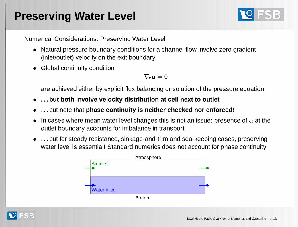
• Natural pressure boundary conditions for a channel flow involve zero gradient(inlet/outlet) velocity on the exit boundary
• Global continuity condition∇•u = 0
are achieved either by explicit flux balancing or solution of the pressure equation
• . . . but both involve velocity distribution at cell next to ou tlet
• . . . but note that phase continuity is neither checked nor enforced!
• In cases where mean water level changes this is not an issue: presence of α at theoutlet boundary accounts for imbalance in transport
• . . . but for steady resistance, sinkage-and-trim and sea-keeping cases, preservingwater level is essential! Standard numerics does not account for phase continuity
Bottom
Atmosphere
Water inlet
Air inlet
Naval Hydro Pack: Overview of Numerics and Capability – p. 13

Preserving Water Level
Numerical Considerations: Preserving Water Level
• Phase continuity condition∂α
∂t+∇•αu = 0
• Integration over the domain D, with discretised phase fluxes:
∫D
∂α
∂tdV +
∮∂D
ds•(uα) = 0
• Preserving water level implies∫D
∂α
∂tdV = 0 and therefore phase continuity must
be explicitly enforced for one phase
• Global continuity equation takes care only of overall (volumetric) flux balance
Water inlet
Bottom
AtmosphereAir inlet
Water inlet
Bottom
AtmosphereAir inlet
Naval Hydro Pack: Overview of Numerics and Capability – p. 14

Relaxation Zones and Boundaries
Naval Hydro Boundary Conditions
• Special boundary conditions with the Naval Hydro pack, usually for u and α
◦ Velocity conditions: moving wall and moving wall slip condition
◦ Water table condition: preserving water level on boundary of moving meshes
◦ Incoming wave conditions, with and without forward speed (regular andirregular waves)
Relaxation Zone Conditions
• Numerical beach boundary condition used to specify a region where the solution isknown or assumed
• Support for forward speed and irregular wave conditions. Example: simulation offreak waves as superposition of known harmonics
• Support for air and water current, with boundary layer profiles
• Also used to pressure waves approaching domain boundaries: numerical beach
• Matrix-implicit formulation : relaxation zones are built into the momentum,pressure and free surface equations
Naval Hydro Pack: Overview of Numerics and Capability – p. 15
Basic Transient Simulations
Basic Transient Simulations
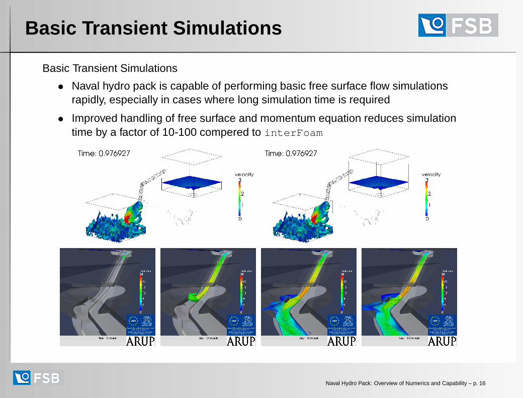
• Naval hydro pack is capable of performing basic free surface flow simulationsrapidly, especially in cases where long simulation time is required
• Improved handling of free surface and momentum equation reduces simulationtime by a factor of 10-100 compered to interFoam
Naval Hydro Pack: Overview of Numerics and Capability – p. 16
Sloshing and Slamming
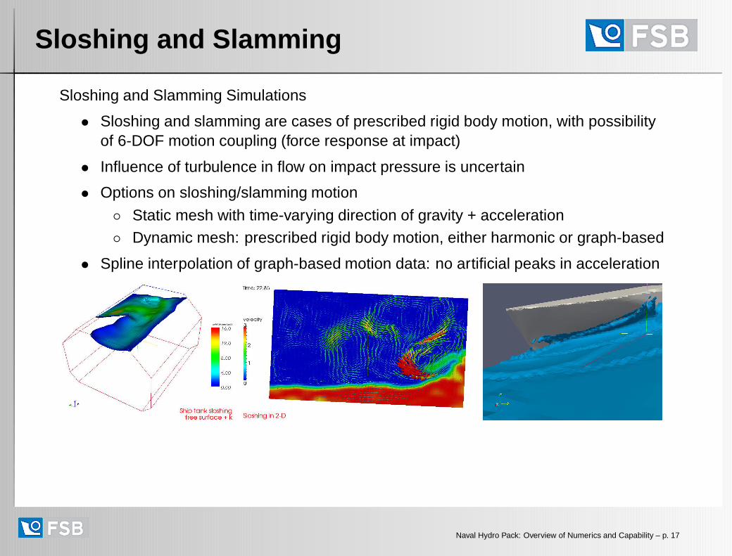
Sloshing and Slamming Simulations
• Sloshing and slamming are cases of prescribed rigid body motion, with possibilityof 6-DOF motion coupling (force response at impact)
• Influence of turbulence in flow on impact pressure is uncertain
• Options on sloshing/slamming motion
◦ Static mesh with time-varying direction of gravity + acceleration◦ Dynamic mesh: prescribed rigid body motion, either harmonic or graph-based
• Spline interpolation of graph-based motion data: no artificial peaks in acceleration
Naval Hydro Pack: Overview of Numerics and Capability – p. 17
Sloshing and Slamming
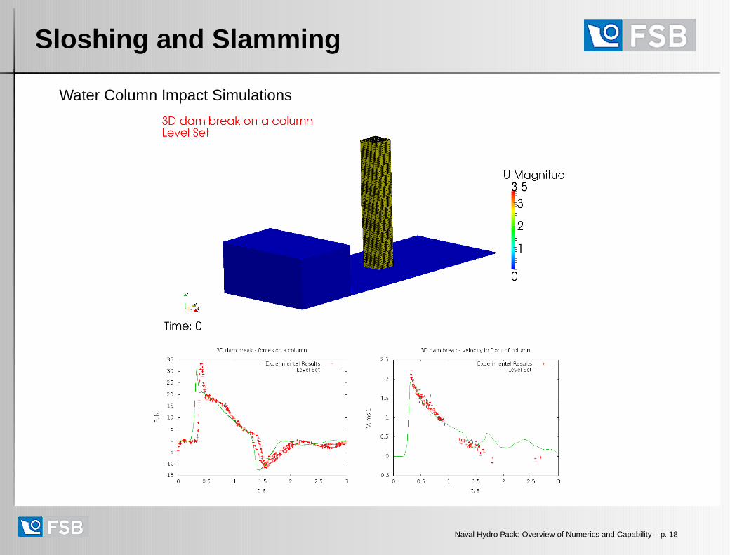
Water Column Impact Simulations
Naval Hydro Pack: Overview of Numerics and Capability – p. 18

Sloshing and Slamming
2-D Slamming Test: Wedge Geometries with Varying Angle: Splash
Naval Hydro Pack: Overview of Numerics and Capability – p. 19

Steady Resistance Simulations
Steady Resistance in Calm Water: KCS Hull
• Using a special “steady-state” formulation of the free surface flow
Naval Hydro Pack: Overview of Numerics and Capability – p. 20

Validation: KCS Hull
Steady Resistance in Calm Water: MOERI Container Ship (KCS)
• Convergence of drag component in pseudo-time
• Study of mesh refinement on a series of meshes: 600k to 4.6M cells
• Note that experiments show unsteady flow at the stern and oscillation in drag data
Naval Hydro Pack: Overview of Numerics and Capability – p. 21

Validation: KCS Hull
Steady Resistance in Calm Water: MOERI Container Ship (KCS)
• Computer: Single processor Intel I7 4820K, 3.7 GHz, 4 cores , 16 GB RAM
Mesh size Drag [N] Simulation Time Converged Forcefor 200 s Simulation Time [s]
600k 41.93 1153 = 19 min 50700k 41.09 1285 = 21 min 50950k 40.35 1752 = 29 min 501.6M 39.93 2996 = 50 min 502.6M 38.91 14249 = 4.0 hrs 125/754.6M 38.58 27888 = 7.7 hrs 125/75
• Force drifts off on finer meshes due to wet stern effect; (also in other codes)
• A converged and accurate resistance force in 30 min on 1 CPU!
• (Note: This is an ugly mesh sequence, y+ values are not refined consistently)
• Other validation cases (5451 hull, proprietary hull shapes) show identicalconvergence behaviour; further mesh refinement studies on appended hulls
• Equivalent simulations performed on all-tet meshes with good results
Naval Hydro Pack: Overview of Numerics and Capability – p. 22
Forced Oscillation Simulations
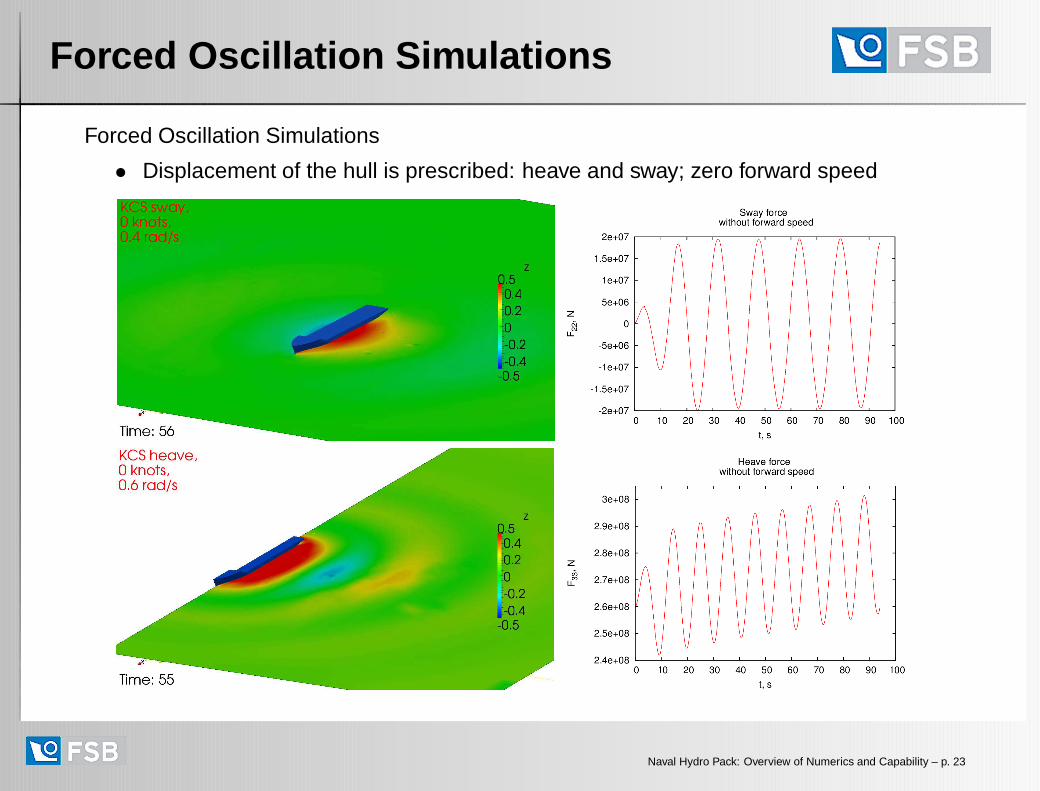
Forced Oscillation Simulations
• Displacement of the hull is prescribed: heave and sway; zero forward speed
Naval Hydro Pack: Overview of Numerics and Capability – p. 23

Forced Oscillation Simulations
Forced Oscillation Simulations with Forward Speed
• Displacement of the hull is prescribed, accounting for forward speed
Naval Hydro Pack: Overview of Numerics and Capability – p. 24
Sea-Keeping Simulations
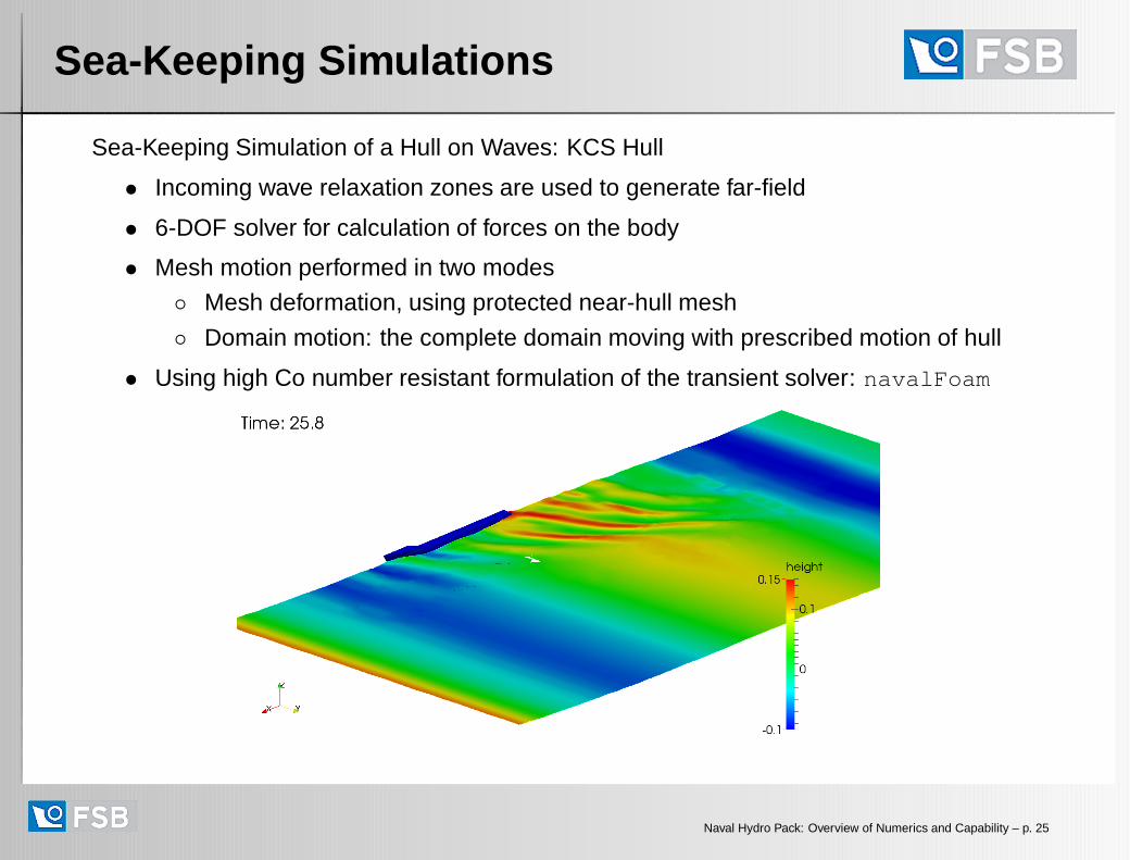
Sea-Keeping Simulation of a Hull on Waves: KCS Hull
• Incoming wave relaxation zones are used to generate far-field
• 6-DOF solver for calculation of forces on the body
• Mesh motion performed in two modes
◦ Mesh deformation, using protected near-hull mesh
◦ Domain motion: the complete domain moving with prescribed motion of hull
• Using high Co number resistant formulation of the transient solver: navalFoam
Naval Hydro Pack: Overview of Numerics and Capability – p. 25

Summary
Naval Hydrodynamics Capability in OpenFOAM
• While the naval hydrodynamics solvers in principle correspond to “standard” freesurface flow formulation, for fast, robust and accurate solvers, special practices areneeded
• Free surface capturing: compressive numerics, relative velocity formulation orLevel Set formulation
• 2 variants of the momentum equation
• Numerical blending of α, pressure and momentum at relaxation zones: implicitnumerical beach, imposition of far field conditions with waves
Naval Hydro Pack: Improvements
• Significant improvement in speed and robustness across the spectrum ofsimulations
• Developed steady and transient high Co number resistant solver. Typical max Conumber 2 000-10 000, with free surface Co number of 100-1 000.
• Inclusion of volumetric relaxation zones for wave generation in far field: blendinganalytical wave equations in relaxation zones with the Navier-Stokes solution inthe region of interest
Naval Hydro Pack: Overview of Numerics and Capability – p. 26