national energy technology laboratory library/research/coal/major...national energy technology...
TRANSCRIPT
National Energy Technology Laboratory
DOE/NETL-2008/1314
Commercial Demonstration of the Manufactured Aggregate Processing Technology
Utilizing Spray Dryer Ash
A DOE Assessment
March 2008
U.S. Department of Energy Office of Fossil Energy
National Energy Technology Laboratory

DISCLAIMER
This report was prepared as an account of work sponsored by an agency of the United
States Government. Neither the United States Government nor any agency thereof, nor
any of their employees, makes any warranty, express or implied, or assumes any legal
liability or responsibility for the accuracy, completeness, or usefulness of any
information, apparatus, product, or process disclosed, or represents that its use would not
infringe privately owned rights. Reference therein to any specific commercial product,
process, or service by trade name, trademark, manufacturer, or otherwise does not
necessarily constitute or imply its endorsement, recommendation, or favoring by the
United States Government or any agency thereof. The view and opinions of authors
expressed therein do not necessarily state or reflect those of the United States
Government or any agency thereof.
Table of Contents
EXECUTIVE SUMMARY .............................................................................................. 5
I. INTRODUCTION ......................................................................................................... 7
II. PROJECT PROCESS DESCRIPTION..................................................................... 9
A. Project Site................................................................................................................ 9 B. Project Goals............................................................................................................. 9 C. Project Description ................................................................................................ 10 D. Technology Description ......................................................................................... 11
III. REVIEW OF TECHNICAL AND ENVIRONMENTAL PERFORMANCE.... 16
A. Technical Performance.......................................................................................... 16 B. Environmental Performance ................................................................................. 19
IV. DISCUSSION OF RESULTS .................................................................................. 20
V. MARKET ANALYSIS .............................................................................................. 22
A. Potential Market .................................................................................................... 22 B. Capital, Operating, and Maintenance Costs........................................................ 23
VI. CONCLUSIONS....................................................................................................... 24
Appendix .......................................................................................................................... 26
3
List of Tables
Table 1. Objectives of Planned Tests During the Demonstration Project ........................ 10 Table 2. Aggregate Production During the Demonstration Project.................................. 19
List of Figures
Figure 1. Process Flow Diagram for Manufactured Aggregate Plant............................... 14
4

EXECUTIVE SUMMARY
The Power Plant Improvement Initiative (PPII) is a follow-up to the U.S. Department of
Energy’s (DOE) Clean Coal Technology Demonstration Program (CCTDP) that was
successfully implemented in the 1980s and 1990s. The purpose of the CCTDP was to
offer the energy marketplace more efficient and environmentally friendly coal-fired
power production options by demonstrating these technologies in commercial settings.
On October 11, 2000, the PPII was established under U.S. Public Law 106-291 for the
commercial-scale demonstration of technologies to ensure a reliable supply of energy
from the Nation’s existing and new electricity generating facilities.
One of the selected projects was titled “Commercial Demonstration of the Manufactured
Aggregate Processing Technology Utilizing Spray Dryer Ash.” The proposal was
submitted by Universal Aggregates, LLC (UA). The project was originally estimated to
cost $19.5 million, of which DOE would provide $7.2 million (37 percent) with the
remaining $12.3 million (63 percent) provided by UA. The UA manufactured aggregate
facility, which occupies a total of approximately five acres, is located at the Birchwood
Power Facility (BPF). The boiler is fired with a low-sulfur West Virginia bituminous
coal. The BPF operates in a load-following mode.
The Cooperative Agreement was awarded on November 14, 2002, construction was
completed in March 2004, and startup was initiated immediately thereafter. The plant
first achieved integrated operation with mixing, extrusion, curing, crushing, and
screening for aggregate production in December 2004; intermittent operation continued
into January, February, and March of 2005. During this period, operation was limited to
about 30 percent of capacity. Two no-cost extensions moved the completion date of the
operating phase of the project to December 31, 2006.
During the 33 months from startup to project’s end, UA encountered numerous
equipment and operating problems that precluded reliable operation and limited operation
5
to values substantially below design levels. UA worked to modify or replace equipment
for the duration of the project. The company reported that the plant was able to operate at
approximately 50 percent capacity at the end of the project. In spite of the various
equipment issues, the product performed well for customers and UA was able to sell all
of the aggregate that was produced.
UA continued to address the equipment problems and, as of December 2007, UA
reported that most of the plant could operate reliably at or near capacity, which is
required to achieve a positive cash flow. UA is committed to solving any remaining
problems and seeks to identify other locations suitable for the manufacture of aggregate
from coal-fired electric generating station waste streams.
6

I. INTRODUCTION
The Power Plant Improvement Initiative (PPII) is a follow-up to the U.S. Department of
Energy’s (DOE) Clean Coal Technology Demonstration Program (CCTDP) that was
successfully implemented in the 1980s and 1990s. The purpose of the CCTDP was to
offer the energy marketplace more efficient and environmentally friendly coal-fired
power production options by demonstrating these technologies in commercial settings.
On October 11, 2000, the PPII was established under U.S. Public Law 106-291 for the
commercial-scale demonstration of technologies to ensure a reliable supply of energy
from the Nation’s existing and new electric generating facilities. Congress directed that
the PPII was to “demonstrate advanced coal-based technologies applicable to existing
and new power plants… The managers expect that there will be at least a 50 percent
industry cost share for each of these projects and that the program will focus on
technology that can be commercialized over the next few years. Such demonstrations
must advance the efficiency, environmental controls, and cost-competitiveness of coal-
fired capacity well beyond that which is in operation now or has been operated to date.”
To fund the PPII, $95 million in previously appropriated funds were transferred from the
DOE’s CCTDP. The PPII program solicitation was issued on February 6, 2001, and
twenty four applications were received. On September 26, 2001, eight applications were
selected for negotiation leading to a Cooperative Agreement. One of the projects selected
was the “Commercial Demonstration of the Manufactured Aggregate Processing
Technology Utilizing Spray Dryer Ash.” The proposal was submitted by Universal
Aggregates, LLC (UA). UA was formed as a joint venture on January 1, 2000, between
CONSOL Energy, Inc., and SynAggs LLC; however, in December of 2003, the interest
of CONSOL Energy, Inc. was purchased by SynAggs LLC. The original project team
consisted of UA, SynAggs, LLC; CONSOL Energy, Inc.; and P. J. Dick, Inc., and the
Cooperative Agreement was awarded on November 14, 2002. The project was estimated
to cost $19.5 million of which DOE would provide $7.2 million (37 percent) with the
remaining $12.3 million (63 percent) provided by UA.
7
The project proposed by UA called for UA to design, construct, and operate a plant that
would convert 115,000 tons of Birchwood Power Facility’s (BPF) spray dryer ash (SDA)
into 167,000 tons of lightweight aggregate. The design is based on converting all SDA
output from BPF. During the course of the project, substantial quantities of lightweight
aggregate were produced and sold. A number of problems that limited production were
encountered and corrected; subsequently, when the project ended on December 31, 2006,
the plant was still not able to consistently meet design production rates, although
reliability and capacity were steadily increasing.
This report is an assessment of the project that was conducted by UA through December
31, 2006.
8
II. PROJECT PROCESS DESCRIPTION
A. Project Site
The UA manufactured aggregate facility is located on approximately five acres, adjacent
to the BPF. The BPF sits on approximately 345 acres in northwest King George County,
Virginia. The BPF consists of a single steam turbine with a nameplate capacity of 250
megawatts. Steam is supplied by a tangentially fired dry-bottom boiler that came online
in 1996. The host plant controls the emission of nitrogen oxides (NOx) with low-NOx
burners and Selective Catalytic Reduction (SCR). A baghouse is used for particulate
control, and a spray dryer absorber controls sulfur dioxide. The baghouse is located
downstream of the spray dryer and removes both the sorbent and the fly ash from the flue
gas. The boiler is fired with a low-sulfur West Virginia bituminous coal and the BPF
operates in a load-following mode.
B. Project Goals
The primary goals of the project were that UA would design, construct, and operate a
lightweight aggregate manufacturing plant at the Birchwood Power Plant, located in King
George, Virginia. During operation as a full-scale commercial facility, the plant was to
use up to 115,000 tons per year of SDA generated at the Birchwood facility to produce
167,000 tons of lightweight aggregate for use in the manufacture of lightweight/medium-
weight concrete masonry block or lightweight concrete. The product had to meet the
appropriate specification (ASTM C331) for these applications and be economically
competitive with lightweight aggregate produced by conventional methods.
This project was carried out to demonstrate the technical and economic viability of large-
scale integrated operation of mixing, extrusion, curing, crushing, and screening with
weigh feeders, screw and belt conveyors, bucket elevators, silos, baghouses, and other
material-handling equipment for aggregate production. The curing vessel (CV) was a
new design for use in a large-scale application, and along with the plant design concept,
had been verified previously in small-scale pilot plant operations in 1999 by SynAggs,
9

LLC. During demonstration, modifications were required to “off-shelf” large-scale
equipment, which was designed for applications other than the processing of SDA.
Short-term tests were conducted to evaluate the effect of operating parameters on the
performance of modified equipment and ash quality and the effect of mix design on
extrusion performance, as presented in Table 1. From the results, UA learned the
operating parameters and limitations required for continuous, integrated operation for
aggregate production.
Table 1. Objectives of Planned Tests During the Demonstration Project
Equipment Objectives
Pug Mill To evaluate the effects of dam and bridge installations in pugmill and water spray system on mixing and extrusion
Pug Sealer To evaluate the effects of pug sealer speed on pug sealer and extruder operations and on properties of green extrudates
Extruder To evaluate the effects of die geometry, liner design, vacuum and additive addition on extruder performance
Curing Vessel To evaluate the effects of operating throughput rate, rotary
distribution chute, adjustable flow dampers, and QA/QC program on curing vessel performance
Screen, Crusher, and Air Classifier
To evaluate the effects of screen decks, rotor speed, and clearance between breaker bar and plate, opening of dampers and choke gate
on size gradation and bulk density of aggregate products
Ash Quality To evaluate the effects of hydrated lime and carbon content on mixing and extruder performance
Mix Design To evaluate the effects of mix formulation (SDA, recycle, additive, and water) on pugmill, pug sealer, and extruder performance
C. Project Description This project was selected for negotiations in September 2001. Negotiations were
completed and a Cooperative Agreement was awarded on November 14, 2002; the
engineering design of the demonstration plant began in November as well. Construction
started in March 2003, the plant was completed in March 2004, and startup of the plant
was initiated in April 2004.
10
The process comprises large-scale integrated operation of mixing, extrusion, curing,
crushing, and screening operations. The new manufacturing facility also incorporates
automatic programmable logic controls, process trending, and data recording.
The plant consists of two metal buildings: the Process Building and the Curing Vessel
Building. These two buildings are connected by two conveyor belts; one conveyor takes
green extrudates to the CV, and the other conveyor moves cured extrudates from the CV
discharge back to the Process Building for crushing and screening. The finished
aggregate is conveyed to a radial stacking conveyor to be stockpiled. Trucks enter the
site and the tare weight is recorded by the automated scale and ticketing system. A front-
end loader loads the trucks, which then return to the scale for gross weight measurement
prior to delivery to the customer.
The Process Building is also connected to the power station’s ash storage silo via an
elevated pneumatic transfer line. The UA plant receives steam and process water from
the BPF. The ash transfer pipeline, the process water line, and a steam supply line are all
on the pipe bridge leading from the power station to the Process Building.
Continuous operation of the extruder was first achieved in July 2004. The CV was first
charged with green extrudates in October 2004 and again in December 2004. A number
of design, construction, and feed problems were encountered during the course of the
project, which will be described in greater detail in Section III of this report.
D. Technology Description The demonstration technology is designed to produce a lightweight aggregate using the
waste stream from a spray dryer absorber as the main feedstock. The demonstration
facility is designed to produce 167,000 tons per year of lightweight aggregate from
115,000 tons of SDA. In addition to water, two proprietary additives (which will be
referred to as “additive #1” and “additive #2”) are mixed with the SDA, which is a
mixture of fly ash, unreacted hydrated lime, and hydrated lime that has reacted with the
sulfur oxides in flue gas to form calcium sulfite and/or calcium sulfate.
11
Unconditioned SDA is received from the power plant and initially stored in the SDA silo
from which it is pneumatically transferred to the SDA day bin. The SDA day bin
discharges material to two separate conveyors. The first stream is discharged to a weigh
feeder that feeds the material to a conveyor that feeds a pugmill. Recycle material from
product screening is also fed to this SDA recycle conveyor and is discharged from the
recycle day bin through a weigh feeder. The second stream from the SDA day bin is fed
through a weigh feeder to the embedding material conveyor where it is mixed with
additive #1 that is fed from a storage silo through a weigh feeder to the embedding
material conveyor.
The SDA recycle material conveyor discharges the dry material to a pugmill. Water and
additive #2 are added and thoroughly mixed with the dry material. The material leaving
the pugmill is a wet, loose, granular material that is discharged to the pugsealer, which
operates under a vacuum and discharges to an extruder. The extruder further mixes the
material then forces it through a die, which is a metal plate that has been drilled with one
or more holes. The wet (green) extrudates drop onto a belt conveyor, which transfers the
material to the tumbler. Embedding material is also fed to the tumbler by the embedding
material conveyor. The tumbler slowly rotates to coat the extrudates and fills the void
spaces between the extrudates. The purpose of the embedding material is to cushion the
soft, wet extrudates and prevent agglomeration during the curing process.
The green extrudates and embedding material discharge from the tumbler to a belt
conveyor that feeds the CV. The CV is a specially designed retention bin that operates
under a slight vacuum and allows the solids to slowly flow downward without channeling
or bridging. The vessel is heat traced and insulated to minimize system heat losses. The
heat tracing is not used to raise the solids temperature, but provides only enough heat to
assure that the CV operates at a constant temperature. The small amount of vent gas
from the CV was originally scrubbed to remove particulate matter; however, the scrubber
was replaced with cartridge filters during the project.
12

13
The pellets cure (harden) as they slowly move down through the vessel. Cementitious
reactions occur in the green extrudates during the curing process, and SDA contains the
essential components for these reactions. The formation of ettringite is believed to be
responsible for some of the pellet hardening. This mineral has the following formula:
Ca6Al2(SO4)3(OH)12·26H2O, or Ca6A12(SO3)3(OH)12·26H2O.
Other cementitious reactions include formation of calcium silicate and aluminates. After
curing, the hardened extrudates are conveyed to the screening operation.
All of the material discharged from the CV is fed to the primary screen that separates the
cured extrudates from the embedding material. The embedding material drops onto the
recycle fines screw conveyor, which transfers the fines to the bucket elevator where they
are then sent to the recycle day bin for use in the production of extrudates. Once largely
free of fines, the cured extrudates are moved to a crusher and are reduced to pellets of
appropriate size for use in the production of concrete blocks. Lastly, the crushed material
is transferred to the secondary screen that splits the crushed aggregate into three streams:
oversize material, product, and fines.
The oversize material (i. e., +3/8”) is recycled through a bucket elevator back to the
crusher. The middle screen product, which is predominately 3/8" x 18 mesh, is the
desired product size and it is conveyed (via a belt conveyor/stacker) to the product
stockpile. The –18 mesh fines go to an inertial separator that uses air classification to
strip most of the -100 mesh fines from the coarser fines. The -100 mesh fines from the
inertial separator are collected in the baghouse and are transferred to the recycle day bin
by the same equipment that recycles the embedding material. The remaining material is
transferred to the product stockpile. The crushing system is designed to minimize the
production of fines and the need to recycle them. The Process Flow Diagram is shown in
Figure 1.
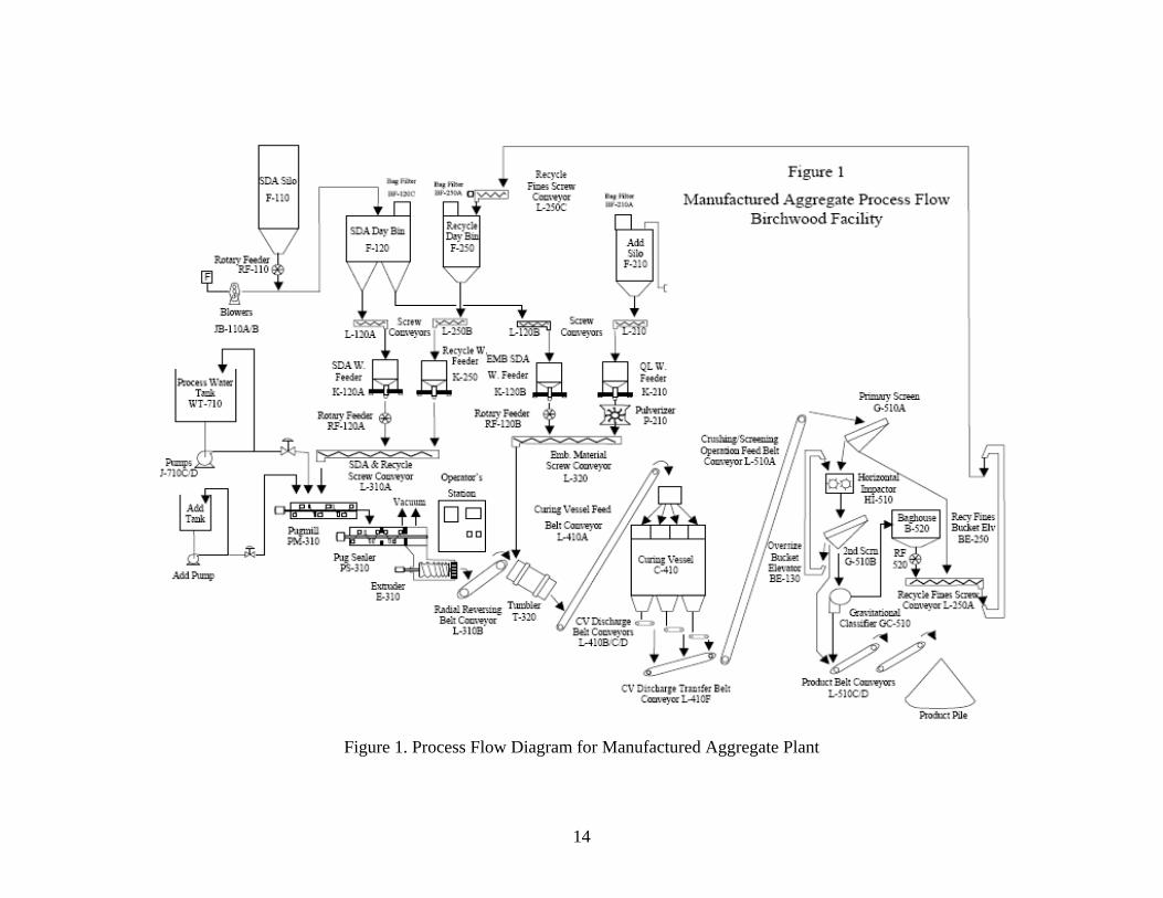
Figure 1. Process Flow Diagram for Manufactured Aggregate Plant
14

The only potential for emissions is the dust that can be generated at various solids
transfer points, from the curing vessel, and the crushing and screening operations. These
potential emission sources are now all equipped with filters. Dust emissions from the
storage pile are controlled with a water spray (on an as-needed basis).
15

III. REVIEW OF TECHNICAL AND ENVIRONMENTAL PERFORMANCE
A. Technical Performance
When initial startup took place in April of 2004, operational problems occurred almost
immediately. (It must be noted that the demonstration plant was subjecting SDA to unique
operations and the CV was a first-of-a-kind design.) The extruder acquired was designed to
operate on clay, not SDA. A further challenge was that the SDA exhibits unusual flow
properties. The length of time over which problems were encountered was largely due to
problems in a piece of equipment that would frequently not be discovered until problems in
upstream equipment were at least partially overcome. For example, problems with the pugmill
would not occur before problems with the feeder were at least partially solved. Operating
problems were addressed for each subsystem comprising the plant.
Shortly after startup, problems were encountered with the SDA feed. As the SDA is
pneumatically conveyed to the SDA day bin, the SDA becomes aerated, which can cause
free-flowing conditions and a loss of mass flow control through the weigh feeders. The
day bin vent baghouse size was increased to help maintain a controlled feed rate. This
increase enabled the operators, by the end of April, 2004, to operate at 10,000 pounds per
hour SDA (about 13 percent of capacity) into the pugmill and pugsealer, and finally to
attempt to feed the extruder.
Throughout the demonstration project, occasional problems were also encountered with
various material transfer equipment items. These problems included failed or damaged
belts and rotary feeders, the recycle chute, and the product oversize chute. These items
were repaired, replaced, or modified as appropriate. In addition to the day bin vent
baghouse, the CV vent wet scrubber experienced problems throughout the demonstration
and was ultimately replaced with a dry cartridge filter.
Problems were also encountered with the quality of the feedstock. An analysis of
extruder difficulties led to the tentative conclusion that the high hydrated lime content of
the SDA feedstock resulted in a material that was too “sticky.” A study was conducted to
16
determine how the BPF could modify the operation of the spray dryer to reduce the
hydrated lime content of the SDA. Once results were implemented to lower the hydrated
lime content of the SDA, this potential variable in SDA composition was reduced, the
operation of the extruder improved, and the operating cost of the spray dryer at BPF was
reduced as well. Some equipment damage resulted from tramp metals and other foreign
material in the SDA received from the BPF. These difficulties were eliminated by the
installation of a magnetic separator and cage-type strainer between the BPF and the SDA
day bin.
The pugmill experienced intermittent problems during the demonstration period. The
first modification was made to improve mixing. The water spray nozzles were replaced
for better wetting, and a dam was installed to increase retention time. Water addition was
increased and a high dam was installed near the pugmill outlet to increase densification of
the wetted SDA. Other changes to the pugmill included the following: the addition of
high-pressure water spray pumps, changing blade positions, and adding a bridge in the
center. Over the course of the project, it was necessary to add new knives and to shut the
unit down for multiple cleanings. It was ultimately determined that the original pugmill
did not have sufficient capacity to meet design production rates, and a new double-shaft
pugmill was designed during the project and installed shortly after the project ended.
UA has reported that it is functioning well.
Like the pugmill, the initial operation of the pugsealer was less than ideal and also
required several cleanings to remove material. A number of modifications were required
to improve contact of the wetted solids and increase densification of the charge at lower
moisture levels. These included:
• Tested an auger with a design volume reduction ratio of 2.5:1 as compared to the
original auger with a design ratio of 1.5:1.
• Modified shell liners to improve axial flow and prevent plugging.
• Modified shear plates to improve axial flow and improve vacuum efficiency.
• Installed new knives and dam.
• Altered the sealing auger interface distance.
17

• Installed a new 400 horsepower variable speed motor.
Initial attempts at extrusion were unsuccessful, due to inaccurate SDA and water-feed
controls, lack of mixing and extrusion consistency, and frequent extruder backup.
Modifications of the pugmill were required to increase mixing time and throughput.
Modifications of the pugsealer were necessary to enhance mixing for extrusion, introduce
adequate vacuum, and control feedrate to the extruder. Replacement of the auger with a
porcelain-enameled auger and modification of the liner and die geometry resulted in
satisfactory extrusion operation.
The CV, which is fed through four pant legs and loading cans, exhibited problems almost
immediately after startup due to unequal flow distribution and plugging. Initially mass
flow distribution was accomplished by passive control through an equally divided
hopper. In addition to the plugging, bridging in the pant legs prevented proper
distribution of the material being fed to the CV. These problems were overcome by
installing a mechanical rotary distribution chute, which was coordinated with the level
indicators in the CV cans. Belt scales were added to confirm CV balance and discharge
rates, and a hopper and vibrating feeder were added to the CV recirculation circuit as
well.
Throughout the project, UA continually worked to evaluate the operational parameters of
the plant to achieve optimal performance. This included not only the best way to operate
the equipment but an evaluation of SDA properties, process water quantities, and
additives. The end result was greatly improved performance and reliability, although not
to expected levels.
The demonstration project formally ended on December 31, 2006. The new double-shaft
pugmill and filters for the CV were installed after the demonstration project ended. UA
reported that the plant was operating at 50–60 percent capacity. Contact with UA after
the project ended indicates that the company continues to make significant progress and
most of the plant’s components are now performing satisfactorily.
18

Production figures are presented in Table 2.
Table 2. Aggregate Production During the Demonstration Project
Date SDA to Pugmill, lb/hr
SDA to Tumbler, lb/hr Recycle, lb/hr Aggregate
Production, tonsDecember 2004 12,000 3,980 – 7470 4,000 –11,820 580 January to March 2005 8,000 –10,000 2,000 – 3,685 700 – 3,670 450 September 2005 15,000 – 22,000 5,500 – 8,500 2,500 –12,000 1,500 December 2005 13,500 – 22,000 6,100 – 9,150 8,100 –13,500 800 January 2006 19,000 – 29,000 8,178 4,000 –14,000 700 February 2006 27,000 – 29,000 8,178 – 8,216 4,000 – 9,000 965 March 2006 26,000 – 29,000 8,178 – 8,716 4,000 – 9,000 627 July 2006 29,000 7,126 0 900 August 2006 22,000 – 29,000 7,126 – 7,880 2,000 – 7,000 3,036 September 2006 11,000 – 26,000 4,325 – 8,182 2,000 – 7,000 1,732 December 2006 12,000 –26,000 3,645 – 7,591 3,000 – 5,000 1,276
B. Environmental Performance
The UA process is inherently environmentally friendly. The process turns a solid waste
into a useful product. Processed SDA and bottom ash not used to manufacture aggregate
will continue to be beneficially utilized as “alternate daily cover” in local landfill
operations. Off-spec aggregate is recycled back through the process. Storm water and
sanitary waste are the only liquid effluents from the plant and are handled in the host
facility systems.
The only potential atmospheric emissions are “fugitive dust” from the various solids transfer
points, crushing and screening operations, and the product storage pile. There is also some
potential for particulate emissions from the vent systems used for equipment that operates under
a slight vacuum. All systems are enclosed and vented through fabric filters. During the project,
some upgrades to the particulate removal systems were required, including the replacement of a
wet scrubber on the CV with a system of cartridge filters. By the conclusion of the project, risks
to the environment were effectively mitigated.
19

IV. DISCUSSION OF RESULTS During the 33 months from initial start-up attempts until the project was completed, the
UA plant produced approximately 26,000 tons of product, equal to about 2 months of
operation at design conditions. In a few cases, production was limited by power outages
or reduced operations at the BPF; however, a large majority of the problems that limited
or prevented operation were due to equipment problems in the UA plant as described in
Section III of this report.
The pugmill/extruder train was originally designed for use with clay, rather than the
materials it was required to process. Since the UA plant was a first-of-a-kind commercial
plant, it is reasonable to assume that no commercially-proven equipment was available
for this particular application. Under such circumstances, significant problems were not
unexpected. Similarly, the CV was an innovative design used in a first-of-a-kind
application, and the need for considerable changes was not unanticipated.
Numerous problems were also encountered in the rest of the facility with such basic items
as conveying/material handling equipment, fabric filters, pumps, spray systems, crushers,
and screen systems. Although the engineering firms and manufacturers of the plant
equipment were well experienced in their respective businesses, the likelihood of
numerous equipment problems and failures always increases when processing a new
feedstock in a new type of facility. In this case, an innovative piece of equipment, the
CV, was also added, further increasing the risks.
UA continued to address the problems by replacing or modifying equipment and
operating procedures, and reported that the plant was able to operate at 50–60 percent of
design capacity by the end of the project. UA’s final report, which covers the period
from the start of the project through the end of 2006, indicates that the company
continues to work on upgrading the plant with the goal of achieving reliable operation at
design capacity.
20

While only 26,000 tons of aggregate products were produced during the project
demonstration, it all found a ready market with the exception of some small quantities
that were used for evaluation tests. The end product consistently met the appropriate
specifications of the customers who used the manufactured aggregate. In 2007, over
41,000 tons of lightweight aggregate were produced and sold after improvements to
mixing and extrusion were introduced.
21

V. MARKET ANALYSIS
A. Potential Market
The immediate market area for the Birchwood manufacturing plant covers over 11,000
square miles. Fifteen concrete masonry production plants operate within the immediate
market area and the annual consumption of lightweight aggregates is relatively steady at
400,000 tons. A strong, steady construction market exists from the greater Baltimore,
Md./Washington, D.C., corridor to south through Richmond, Va., and on towards
Chesapeake, Va. The demand for all basic construction materials (including lightweight
aggregate) is estimated to remain steady, if not increase slightly for the foreseeable
future. Residential and commercial development are expected to remain strong in the
foreseeable future. The resulting demand for concrete masonry products consumes much
of the lightweight aggregate market share. Extended market areas exist west and north of
the Birchwood plant. With the possibility of rail transportation, this extended market
area provides access to an additional thirteen concrete masonry production plants and up
to 200,000 tons of lightweight aggregate consumption annually.
Additional lightweight aggregate market potential exists for lightweight structural
concrete in applications such as structural embankments. The demand within these
markets varies annually between 50,000 tons and 150,000 tons due to annual fluctuations
in the demand for high-rise, multi-level building construction, bridge construction and
rehabilitation, and highway construction activities.
UA reports that its market research located many potential sources of raw feedstock
materials; however, not all potential sources of raw feedstock materials fit the business
model. Since basic supply/demand economics prevail, an end product market must be
reasonably accessible, and the aggregate competitively priced. In addition, a minimum
supply of quality feedstock materials must be available to justify the financial investment
with the required rate of return. Where the appropriate market conditions exist, UA states
that it will perform the necessary due diligence to expand the commercial deployment of
the manufactured aggregate technology.
22
B. Capital, Operating, and Maintenance Costs
UA conducted a cost analysis based on projected performance of the Birchwood facility;
the analysis forecast an actual operating budget for calendar year 2007, using the 2006
year-end production rate of 72,000 tons of lightweight aggregate produced and sold.
(This level of production was not maintained and only 41,000 tons were produced in
2007.) The projected performance was based primarily upon estimated annual
production at approximately 50 percent of the design operating capacity and the
corresponding lightweight aggregate sales from that production. UA performed a
sensitivity analysis for cost-based performance at three annual production forecast cases
using the current staffing requirement of twenty hourly and salary employees at the
Birchwood manufacturing plant. The company concluded that the demonstration project
must operate at, or very near, full production capacity to experience a positive net cash
flow.
Due to the extensive start-up problems and modifications, the costs that were and are
being incurred at Birchwood cannot be used as a reliable estimate for future facilities.
(These costs are included in the appendix for general information.) However, given the
post-project plant refinements and continued operation at increased capacity, UA is
currently gaining valuable operation and maintenance experience. This experience will
allow the organization to realistically budget annual operating costs and estimate costs for
future implementation of this technology.
23

VI. CONCLUSIONS The manufactured aggregate plant has experienced nearly continuous operating problems
and equipment failures since its initial startup in April 2004. During the course of the
project, UA continued to modify or replace equipment and operational procedures, which
resulted in approximately 50 percent operational plant capacity at the end of the project.
Given the inability of the demonstration plant to achieve the design production rate in the
course of the project, the project cannot be considered to be fully successful, especially
since UA analysis determined that the plant must operate at or near full design capacity to
generate a positive cash flow. It must also be noted, however, that UA was able to sell
the entire product and that the manufactured aggregate does meet the needs of its
customers. Manufactured aggregate has several advantages over competing materials
(primarily expanded clay and shale). The manufactured aggregate uses a waste stream as
the primary feed thereby avoiding landfill disposal costs, eliminates the need to mine raw
materials, and unlike clay and shale, it does not require the fuel needed to fire a kiln.
Communication with the participant in December 2007 confirmed that UA has continued
to address the problems that limit production. The front end of the plant was operating at
or near design capacity and the CV problems have been largely overcome. This was
accomplished in large part due to the lessons learned during the demonstration project.
The only major impediment to full production is in the crushing/screening of the cured
extrudates. While issues such as these still exist, UA’s success in addressing the many
problems that have occurred indicates that there is a reasonable probability the plant will
meet its goals, albeit at a later date than initially planned.
24

REFERENCES Cairns, Gary, and Paul Yuran, Universal Aggregates, LLC, Personal Communication, December 7, 2007. R. T. Patterson Company, Inc., “Commercial Demonstration of the Manufactured Aggregate Processing Technology Utilizing Spray Dryer Ash – Topical Report #1-Public Design Report,” April 2003. Wu, Milton and Paul Yuran, “Commercial Demonstration of the Manufactured Aggregate Processing Technology Utilizing Spray Dryer Ash - Final Technical Report,” September 26, 2007.
25

Appendix Project Costs
26

27